Article

Intelligent Fault Diagnosis of Ball Bearing Induction Motors for Predictive Maintenance Industrial Applications

by
Vasileios I. Vlachou
1,
Theoklitos S. Karakatsanis
2,*,
Stavros D. Vologiannidis
3,
Dimitrios E. Efstathiou
3,
Elisavet L. Karapalidou
3,
Efstathios N. Antoniou
4,
Agisilaos E. Efraimidis
3,
Vasiliki E. Balaska
2 and
Eftychios I. Vlachou
3
1
School of Electrical and Computer Engineering, National Technical University of Athens, 15780 Athens, Greece
2
Department of Production and Management Engineering, Democritus University of Thrace, 67100 Xanthi, Greece
3
Department of Computer, Informatics and Telecommunications, International Hellenic University, 62124 Serres, Greece
4
Department of Informatics and Electronics Engineering, International Hellenic University, 57400 Thessaloniki, Greece
*
Author to whom correspondence should be addressed.
Machines 2025, 13(10), 902; https://doi.org/10.3390/machines13100902
Submission received: 25 August 2025 / Revised: 15 September 2025 / Accepted: 19 September 2025 / Published: 2 October 2025
(This article belongs to the Special Issue Vibration Detection of Induction and PM Motors)

Abstract

Induction motors (IMs) are crucial in many industrial applications, offering a cost-effective and reliable source of power transmission and generation. However, their continuous operation imposes considerable stress on electrical and mechanical parts, leading to progressive wear that can cause unexpected system shutdowns. Bearings, which enable shaft motion and reduce friction under varying loads, are the most failure-prone components, with bearing ball defects representing most severe mechanical failures. Early and accurate fault diagnosis is therefore essential to prevent damage and ensure operational continuity. Recent advances in the Internet of Things (IoT) and machine learning (ML) have enabled timely and effective predictive maintenance strategies. Among various diagnostic parameters, vibration analysis has proven particularly effective for detecting bearing faults. This study proposes a hybrid diagnostic framework for induction motor bearings, combining vibration signal analysis with Support Vector Machines (SVMs) and Artificial Neural Networks (ANNs) in an IoT-enabled Industry 4.0 architecture. Statistical and frequency-domain features were extracted, reduced using Principal Component Analysis (PCA), and classified with SVMs and ANNs, achieving over 95% accuracy. The novelty of this work lies in the hybrid integration of interpretable and non-linear ML models within an IoT-based edge–cloud framework. Its main contribution is a scalable and accurate real-time predictive maintenance solution, ensuring high diagnostic reliability and seamless integration in Industry 4.0 environments.

1. Introduction

In recent decades, induction motors (IMs) have become the backbone of modern industrial applications, playing a vital role in manufacturing, energy conversion, robotics, transportation, and automation systems due to their durability, simplicity of construction, low cost, and high power-to-weight ratio [1,2]. Despite their reliability, induction motors are susceptible to various faults caused by harsh operating conditions, aging, poor lubrication, load variations, or environmental factors. Among these, bearing-related faults are the most prevalent, accounting for approximately 41–42% of all failures in industrial IMs according to IEEE and EPRI statistical analyses [3]. Since rolling-element bearings ensure the smooth and efficient operation of rotating machinery, any degradation in their performance can lead to reduced efficiency, unplanned downtime, increased maintenance costs, or even catastrophic system failure [4]. To address this critical issue, industrial stakeholders are transitioning from reactive and preventive maintenance schemes to predictive maintenance (PdM) strategies. Predictive maintenance involves real-time monitoring of equipment health and applying diagnostic algorithms to anticipate failures before they occur, optimizing resource allocation and minimizing production losses [5]. This transition is largely driven by the emergence of Industry 4.0, which combines cyber–physical systems (CPSs), the Industrial Internet of Things (IIoT), edge computing, cloud services, and artificial intelligence (AI) [6,7]. These technologies enable the continuous acquisition, processing, and analysis of operational data through intelligent sensors, making real-time condition-based maintenance a feasible and scalable solution.
Vibration analysis is currently one of the most widely adopted methods for assessing the health of bearings. It enables the detection of characteristic fault frequencies associated with inner and outer race defects, ball defects, and lubrication issues [8]. However, the effectiveness of vibration-based diagnostics depends heavily on signal quality, proper sensor placement, and the application of advanced data-driven techniques for pattern recognition and classification. Among the computational techniques, Machine Learning (ML) and Deep Learning (DL) have shown significant promise in automating the fault diagnosis process [9]. These methods are capable of learning from complex and non-linear data distributions, offering superior accuracy over traditional signal processing techniques. Notably, Support Vector Machines (SVMs), Convolutional Neural Networks (CNNs), Multilayer Perceptrons (MLPs), and ensemble learning approaches such as Gradient Boosting and XGBoost are increasingly used in PdM systems [10,11,12]. Their effectiveness has been demonstrated in both laboratory and real-world scenarios involving various types of IM faults.
This study contributes an intelligent diagnostic framework for bearing fault detection in induction motors by combining vibration signal analysis with machine learning models (SVMs and ANNs) in an IoT-enabled architecture. The framework leverages IO-Link sensors, edge computing, and cloud integration to enable scalable and real-time monitoring. Validation on an experimental dataset including multiple lubrication states and structural defect scenarios demonstrates its effectiveness and practical applicability. Several recent studies have explored machine learning-based approaches for induction motor fault diagnosis, combining methods such as SVMs, neural networks, and boosting techniques to enhance classification accuracy. For example, Kim et al. [13] proposed a framework integrating SVMs, neural networks, and boosting methods to effectively identify various motor faults under laboratory conditions. Building upon this line of research, the present study proposes a hybrid intelligent diagnostic framework that integrates SVMs and ANNs within an Industry 4.0-compliant IoT architecture extending the approach to real-time, scalable, and industrially deployable monitoring.
The rest of this paper is structured as follows. Section 2 provides a comprehensive review of the state-of-the-art in intelligent fault diagnosis of induction motor bearings, with emphasis on ML and DL methods. Section 3 introduces the main characteristics of vibration signals and presents the theoretical background of fault-specific frequency patterns (BPFO, BPFI, BSF, FTF) that enable fault localization and identification in bearing systems. Section 4 describes the experimental setup, data acquisition system, and modeling framework. Section 5 presents the results and comparative analysis of the proposed methodology. Finally, Section 6 concludes the paper and outlines directions for future work.

2. Fault Diagnosis Techniques

This section provides a structured literature review of existing fault diagnosis techniques for induction motor bearings. While some aspects overlap with the general background presented in the Introduction, the aim here is to offer a more detailed and systematic overview. This review highlights the strengths and limitations of prior approaches and motivates the use of SVMs and ANNs in the proposed framework. By presenting this material in a dedicated section, the Introduction is kept concise, while readers are still provided with a comprehensive technical foundation before the methodology is introduced.
Vibration analysis remains the cornerstone of bearing fault diagnosis in rotating electrical machines due to its sensitivity, diagnostic richness, and early-stage fault detection capability. Rolling element bearings produce distinct vibration signatures depending on the type and severity of defect, such as spalls or cracks in the inner/outer race, rolling elements, or cages. These signatures manifest as characteristic fault frequencies that are functions of bearing geometry and rotational speed. Over the past decades, this approach has been widely applied in both industrial and research contexts and further refined through advances in signal processing and sensor technologies [14].
Traditional methods focus on time-domain and frequency-domain analysis. Time-domain indicators like root mean square (RMS), kurtosis, skewness, crest factor, and peak amplitude are often the first-line features for monitoring signal energy or impulsiveness [15,16]. However, their diagnostic reliability is limited in complex or noisy environments. Consequently, frequency-domain methods such as Fast Fourier Transform (FFT) and envelope analysis became dominant due to their capacity to isolate defect-specific frequency bands [17,18]. To overcome the non-stationary nature of real-world vibration signals, time–frequency representations have been employed. Short-Time Fourier Transform (STFT), Wavelet Transform (WT), and Empirical Mode Decomposition (EMD) have allowed dynamic spectral analysis, enabling the detection of transient and incipient faults in varying speed conditions [19,20,21]. In particular, Wavelet Packet Decomposition (WPD) has proven effective for isolating energy components of fault-induced vibrations in specific frequency bands [22].
Recent developments integrate advanced statistical metrics and adaptive signal decomposition methods, such as Hilbert–Huang Transform (HHT) and Variational Mode Decomposition (VMD), which exhibit higher robustness in handling non-linear and time-varying phenomena [23,24]. These techniques facilitate envelope extraction and demodulation of modulated signals caused by cyclic impacts—critical for early fault detection in bearings. Moreover, multisensor fusion approaches, where vibration data is combined with acoustic, current, or temperature measurements, have shown promise in increasing diagnostic accuracy and robustness [25]. However, even standalone vibration analysis, when enhanced with adaptive filtering, denoising, and advanced time–frequency techniques, remains a practical and effective tool for predictive maintenance systems, particularly in Industry 4.0 environments.
Acoustic emission (AE) analysis has emerged as a complementary and powerful technique for detecting early-stage bearing faults, particularly those involving surface degradation, micro-cracking, or lubrication deficiencies. AE refers to the high-frequency elastic waves generated by rapid energy releases within materials, such as crack initiation or frictional slip. Unlike vibration signals, which primarily capture lower-frequency responses from macroscopic motion, AE signals contain high-frequency information (typically > 100 kHz), enabling detection of subtle incipient faults often missed by conventional methods. The main advantage of AE is its sensitivity to microscopic changes, making it ideal for early fault detection before severe damage occurs. Caesarendra et al. [26] reviewed AE-based condition monitoring methods and their applications for low-speed slew bearings, highlighting the effectiveness of AE in capturing early fault signatures. Hemmati et al. [27] experimentally investigated the statistical parameters of AE signals in rolling element bearings, showing that parameters such as hit count, rising time, energy, and amplitude are sensitive to fault presence and severity under varying load and speed conditions. Furthermore, Tang et al. [28] conducted a comparative study of vibration and AE signals for fault diagnosis in low-speed bearings, demonstrating that AE event extraction using short-time autocorrelation function (STAF) enhances the identification of fault-induced pulses, providing reliable diagnostics even in challenging operational scenarios. Collectively, these studies confirm that AE analysis, especially when combined with advanced signal processing techniques, offers a robust approach for early detection and monitoring of bearing faults, complementing traditional vibration-based methods.
Recent advances in deep learning have significantly enhanced the accuracy and scalability of bearing fault diagnosis systems, especially in the context of Industry 4.0, where large volumes of heterogeneous sensor data are readily available. Hybrid multimodal fusion techniques, which integrate vibration and acoustic emission signals, have been shown to improve the robustness of diagnostic models by leveraging complementary information from multiple sensing modalities. Che et al. [29] proposed a deep learning framework that utilizes multimodal fusion and feature extraction to achieve high diagnostic accuracy, demonstrating superior performance over single-sensor approaches. In a similar direction, Zhang et al. [30] introduced a novel architecture based on variable pooling multiscale convolutional neural networks (VPMCNNs), which effectively captures multiscale features from raw acoustic emission signals, leading to improved classification performance under both constant and variable operating conditions. Moreover, traditional shallow learning architectures are increasingly replaced by deep neural networks that can automatically extract hierarchical features from complex time–frequency representations. He and He [31] developed a deep learning method employing short-time Fourier transform (STFT) and a LAMSTAR neural network, which achieved reliable fault classification using acoustic signals collected from experimental bearing rigs. Zhao et al. [32] provided a comprehensive overview of deep learning applications in machine health monitoring, emphasizing the superiority of convolutional and recurrent neural networks in extracting discriminative features from non-stationary signals. Alongside algorithmic development, sensor placement remains a critical consideration in ensuring signal quality and observability of fault characteristics. Dai et al. [33] proposed an optimal sensor placement strategy for modal identification in rotating machinery, considering both the number and spatial configuration of sensors, thus enhancing the efficacy of monitoring systems.
Motor Current Signature Analysis (MCSA) has proven to be a non-invasive and cost-effective technique for detecting bearing faults in induction motors. However, the faint fault signatures in current signals—often buried within dominant supply harmonics—pose significant challenges. To boost diagnostic performance, recent studies have integrated advanced filtering approaches with Support Vector Machine (SVM) classifiers. A recent comprehensive review by Niu et al. [34] systematically outlines the state-of-the-art in MCSA-based fault diagnosis, summarizing techniques ranging from traditional spectral and demodulation analyses to time–frequency and AI-driven approaches. The authors note that the successful deployment of MCSA hinges on effective noise suppression and robust feature extraction under varying load and speed conditions.
Building on this foundation, Jonjo et al. [35] proposed a multi-stage pipeline—time-shifting to attenuate supply harmonics, optimized Variational Mode Extraction (VME) using Black Widow optimization, followed by CNN-SVM classification on 2D current representations—achieving over 95% accuracy. Similarly, Dalvand et al. [36] introduced time-shifting combined with demodulation filters and SVMs to isolate fault-related current components, significantly improving SNR. Further advancing classifier techniques, Khadem Hosseini et al. [37] merged Wavelet-based feature extraction and Kernel PCA with a projection-based SVMs optimized via a Projection Recurrent Neural Network (PRNN), boosting detection fidelity in bearing fault tests. These hybrid frameworks illustrate the strength of combining signal preprocessing with powerful, adaptive SVM classifiers.
Still, there’s room for improvement. Challenges such as fluctuating torque, unbalanced hosts, and supply distortions require more adaptive decomposition methods like Variational Mode Decomposition or Adaptive EMD. Moreover, dynamic SVM parameter tuning and real-time edge implementation are essential for Industry 4.0 deployment. Together, these advances spotlight a clear trend: merging advanced filtering techniques (time-shift, VME, wavelets) with SVM-based ML models substantially enhances MCSA diagnostics, aligning well with the needs of scalable, reliable, and field-deployable predictive maintenance systems.
Infrared Thermography (IRT) has emerged as a non-invasive and non-contact diagnostic technique for detecting incipient faults in induction motors, especially in situations where physical sensors might be impractical or intrusive. Recent advancements have combined IRT with machine learning (ML) and deep learning (DL) methods to extract meaningful thermal patterns associated with bearing, rotor, and lubrication-related faults. In [38], Atif et al. proposed a hybrid approach integrating classical ML and DL techniques, achieving 98.29% classification accuracy using SVMs and 100% using a simplified CNN, thereby demonstrating high efficiency in identifying various bearing defects through statistical and GLCM-based features. Similarly, Javed et al. [39] utilized Local Octa Pattern (LOP) features in conjunction with genetic algorithms and SVM classifiers to detect overload and fault conditions, showcasing robust real-time performance with infrared datasets. Molina et al. [40] applied a lightweight neural network trained via the Google Teachable Machine to classify four fault types (bearing and rotor bar defects), deployed on embedded systems for live monitoring, proving the feasibility of edge deployment in industrial settings. Kulkarni et al. [41] provided a broad survey of thermal imaging-based fault detection techniques across different machine types, emphasizing the versatility of DL algorithms such as CNNs in handling complex image-based diagnostics. Finally, Kilickaya et al. [42] introduced a novel self-organized operational neural network (Self-ONN) architecture for fault diagnosis in squirrel-cage induction motors. The proposed model achieved comparable performance to deeper CNNs like ResNet and EfficientNet, while being significantly lighter and suitable for edge deployment scenarios with limited computational resources.
The diagnostic techniques of vibration analysis, acoustic emission, motor current signature analysis (MCSA), and infrared thermography (IRT) offer complementary insights into bearing health, each excelling under specific operating conditions and fault types. Vibration and acoustic emission provide high sensitivity to early localized defects, while, MCSA enables non-intrusive monitoring, and IRT supports contactless surface temperature assessment. Accurate fault type and severity identification, depend on extracting distinctive features—such as frequency peaks, amplitude modulations, and thermal gradients—that serve as indicators of specific fault mechanisms and are essential for reliable automated diagnosis. Despite their proven effectiveness, most existing studies either rely on controlled laboratory datasets or single diagnostic models. The novelty of this work lies in integrating a hybrid intelligent diagnostic framework, combining Support Vector Machines (SVMs) and Artificial Neural Networks (ANNs), within an Industry 4.0-compliant IoT architecture. Validated on a custom experimental dataset incorporating diverse lubrication and structural bearing faults, this framework balances interpretability with predictive accuracy and is designed for real-time industrial deployment. As feature extraction is a critical step, the following section introduces the characteristic vibration signal features and fault-specific frequency patterns forming the basis of the proposed methodology.

3. Signal Features and Fault Signatures in Bearing Diagnosis

This section provides the theoretical foundation of bearing fault frequencies and fault signatures, which are directly related to the experimental states analyzed in Section 4. In vibration-based diagnosis of rolling element bearings, early and accurate fault diagnosis relies heavily on identifying specific frequency components generated by the dynamic interactions of defective bearing elements. These frequency components as shown in Table 1, known as characteristic fault frequencies (CFFs), are deterministic and can be derived from the bearing’s geometry and the motor’s rotational speed. Each bearing fault—whether located on the outer race, inner race, rolling element, or the cage—produces a unique frequency signature due to the periodic impact events that arise as the defective component interacts with the rest of the system during rotation. The most used CFFs are the following:
These fault frequencies are embedded in the vibration spectrum of the motor and can be used as diagnostic indicators. The accurate calculation of CFFs enables fault localization (inner race, outer race, ball, or cage) and supports classification models by serving as ground-truth frequencies for both feature extraction and validation. When a fault is present, harmonics and sidebands around these frequencies may appear, particularly when the fault is severe or when amplitude modulation occurs due to load or speed variations.
Consequently, most signal processing and feature extraction techniques (e.g., envelope analysis, spectral kurtosis, time-frequency transforms) aim to enhance and isolate these fault frequencies from noise and non-relevant components. These frequencies manifest in real signals and they are detected and leveraged by diagnostic algorithms. The effectiveness of any intelligent fault diagnosis system for rolling element bearings critically depends on the quality of features extracted from the raw signals. These features are derived either from the time domain or the frequency domain of the vibration signal and are chosen based on their sensitivity to bearing faults and their ability to discriminate among different fault types and severities.
Time-domain features are statistical descriptors directly computed from the amplitude of the vibration signal over time. These features are straightforward to compute and do not require transformation into another domain, making them attractive for real-time and embedded diagnostic systems. Commonly used time-domain features include: Root Mean Square (RMS), Peak-to-Peak Value (P2P), Crest Factor (CF), Kurtosis (K), Skewness, Impulse Factor (IF) [47]. These features can provide early indicators of degradation when tracked over time in a condition monitoring system. However, they may be insufficient under noisy or variable-speed conditions, where fault-induced components are buried under broadband noise.
Frequency-domain features are obtained by transforming the vibration signal using the Fast Fourier Transform (FFT) or other spectral techniques. They allow for isolation of specific frequencies associated with known fault mechanisms, such as the CFFs. The key frequency-domain features include Spectral Energy, Spectral Kurtosis (SK), Sideband Analysis, Amplitude at CFFs, Power Spectral Density (PSD), and Envelope Spectrum Peaks. Envelope analysis, typically combined with the Hilbert transform, helps extract modulated fault components from high-frequency resonance regions. Peaks in the envelope spectrum at CFFs confirm the existence of localized defects. These frequency-domain features are critical in robust fault diagnosis, particularly when the motor operates under varying load or speed. Moreover, they facilitate explainable AI models, where each frequency component has a known physical interpretation.
In bearing fault diagnosis, the visual examination of vibration signals—particularly in the time and frequency domains—provides critical insight into the underlying mechanical condition of the bearing. Different fault types, such as outer race, inner race, ball, or cage defects, exhibit distinct dynamic responses that are observable in the form of periodic impulses, sidebands, and energy concentration at specific fault frequencies. These frequencies, namely the Ball Pass Frequency Outer race (BPFO), Ball Pass Frequency Inner race (BPFI), Ball Spin Frequency (BSF), and Fundamental Train Frequency (FTF), form the diagnostic foundation for vibration-based monitoring systems. Their presence, intensity, and evolution in the recorded signals allow for the discrimination between different fault severities and locations.
In the time domain, a localized defect on the outer or inner race leads to recurrent impulsive responses as the rolling elements strike the damaged surface. These impulses, though sometimes masked by system noise or other mechanical interactions, can be revealed through techniques such as the envelope analysis or high-resolution filtering. A healthy bearing typically exhibits a low-amplitude, broadband response, while a defective bearing demonstrates sharp periodic bursts with increased amplitude and kurtosis, especially when the fault size grows. The corresponding frequency spectra show harmonics centered around the shaft rotation frequency and modulated by the bearing characteristic fault frequencies. For example, an outer race fault will produce a series of spectral peaks spaced at the BPFO, while an inner race fault leads to similar patterns around the BPFI, with modulations affected by the rotational speed of the shaft and the number of rolling elements [21].
In the frequency domain, envelope spectra derived from demodulation techniques are particularly powerful. These representations isolate modulated high-frequency components associated with repetitive impacts. Such impacts result in prominent spectral lines at the BPFO, BPFI, or BSF, depending on the fault location. As reported in Randall and Antoni [18], the sideband structure and the spacing between spectral lines provide an important diagnostic cue, allowing for the detection of compound or multiple defects. Antoni [19] introduced the kurtogram as a tool to automatically select the frequency band that contains the highest impulsiveness, guiding the analyst to the frequency range where the defect signature is most pronounced.
Other studies have demonstrated the efficacy of combining statistical analysis, time–frequency transforms, and sparse signal decomposition for fault identification. Yang et al. [20] applied basis pursuit decomposition to isolate defect-induced transients from the overall vibration response, enhancing the visibility of fault signatures. Similarly, Kankar et al. [17] employed the wavelet transform to distinguish inner and outer race defects through transient energy concentration and localized signal behavior. These visualization techniques not only aid in fault classification but also contribute to the validation of automated diagnostic algorithms, offering a benchmark for supervised and unsupervised learning approaches.
Figure 1a presents the typical schematic structure of a bearing with its individual parts while Figure 1b illustrates various types of failures (red color arrows show the outer race and inner ball race fault) that can result from severe mechanical stress. The accuracy and reliability of each method applied depends largely on the vibration data collected by accelerometers. The placement of the sensor on both the electrical motor and the bearings plays a critical role in the post-processing signal. Research has shown that placing the vibration sensor on the Z-axis of the machine, in the same direction as the rotor, presented the highest sensitivity to inner race fault, providing more reliable results [48].
The inclusion of such representative vibration patterns in a diagnostic framework facilitates interpretability, especially when the system is deployed in real-time industrial environments. It enables maintenance engineers to visually confirm the classification outputs of machine learning models and enhances trust in predictive maintenance solutions, particularly when combined with sensor fusion or cloud-based monitoring architectures. Research efforts have been particularly focused on identifying both localized and distributed faults that are considered complex to locate. Incorporating a multi-sensory system collecting data through vibration, current measurements and magnetic field leakage measurements on different varieties of faults in bearings a deep machine learning (2D-CNN) model was utilized which takes as input images generated from a set of samples and the CNN identifies characteristic patterns [49].
The extraction of features from vibration signals acquired from induction motors often results in high-dimensional datasets containing numerous descriptors from the time, frequency, and time-frequency domains. However, not all extracted features contribute equally to fault classification. Many features may be redundant, irrelevant, or noise-sensitive, which can degrade model performance and lead to overfitting. Therefore, selecting the most discriminative features and reducing the dimensionality of the input feature vector are critical steps in developing efficient and interpretable fault diagnosis systems. Utilizing an excessive number of features increases model complexity, prolongs training times, and can hinder generalization, especially when working with limited training data. Additionally, deploying diagnostic algorithms in real-time environments or on edge-computing platforms demands compact yet informative feature subsets. To address these challenges, both supervised and unsupervised feature selection methods are employed.
Principal Component Analysis (PCA) is one of the most widely used techniques for dimensionality reduction. It transforms the original features into a new orthogonal space that captures the directions of maximum variance. Although PCA effectively reduces dimensionality, its main drawback lies in the loss of interpretability, as the new principal components are linear combinations of the original features. In cases where interpretability is crucial, the Minimum Redundancy Maximum Relevance (mRMR) method is preferred. Based on mutual information theory, mRMR selects features that are highly relevant to the class labels while minimizing redundancy among them.
Relief-F is another supervised method that estimates the importance of each feature by comparing the distances between similar and dissimilar samples in the feature space. A commonly adopted approach in bearing fault diagnosis is the use of Support Vector Machine Recursive Feature Elimination (SVM-RFE), which iteratively removes the least relevant features based on the weight vector of an SVM model. Although computationally demanding, SVM-RFE yields highly optimized and compact feature subsets with excellent classification capabilities. In addition, statistical techniques such as Fisher Score and Analysis of Variance (ANOVA) are utilized to assess the discriminative power of individual features by comparing intra-class and inter-class variances. Features with high Fisher scores are considered more informative for classification tasks and are therefore retained in the final feature set.
Following feature selection, further dimensionality reduction may be applied to enable efficient model training and deployment, especially in industrial scenarios involving embedded systems and IoT devices. Advanced techniques such as autoencoders or t-distributed stochastic neighbor embedding (t-SNE) are used for non-linear data compression and visualization in reduced dimensional spaces. It is also important to emphasize the value of physically meaningful features in the context of condition monitoring and maintenance. Features such as RMS amplitude, spectral energy density, peak values in the envelope spectrum, and statistical descriptors like kurtosis or skewness provide interpretable insights into the health status of bearings. These features often correlate directly with specific types of faults such as inner race defects, outer race defects, or lubrication issues. Hence, the final feature vector used in classification is typically composed of selected metrics from the time and frequency domains that are both statistically significant and physically relevant, thereby enhancing the robustness and transparency of the diagnostic model.
In this study, vibration analysis was selected as the primary diagnostic method due to its high sensitivity and low cost, while time-domain and frequency-domain features were extracted to characterize bearing conditions. Statistical indicators—including RMS, crest factor, kurtosis, skewness, and peak-to-peak values—were computed. Additionally, spectral features obtained through Fast Fourier Transform (FFT) and envelope analysis to capture characteristic fault frequencies (BPFO, BPFI, BSF). These processed features formed the basis for training the machine learning models. Compared to other diagnostic approaches, motor current analysis offers non-invasive and economical monitoring, (infrared thermography is affected by environmental conditions, and acoustic emission is effective for detecting early microcracks but is more complex and costly). A literature search indicates that multimodal fusion of these signals can enhance diagnostic robustness, however, industrial adoption requires careful consideration of sensor layout and implementation costs [50]. The following section details the experimental setup and methodology used to collect vibration signals and implement the proposed diagnostic framework.

4. Proposed Fault Detection Methodology

4.1. Experimental Validation

Accurate and reliable data collection requires the appropriate experimental setup built with the aim of identifying failures in bearings that have a wide range of use in industry. The experimental setup shown in Figure 2 includes a small size and power (1) induction motor system with the basic characteristics presented in Table 2.
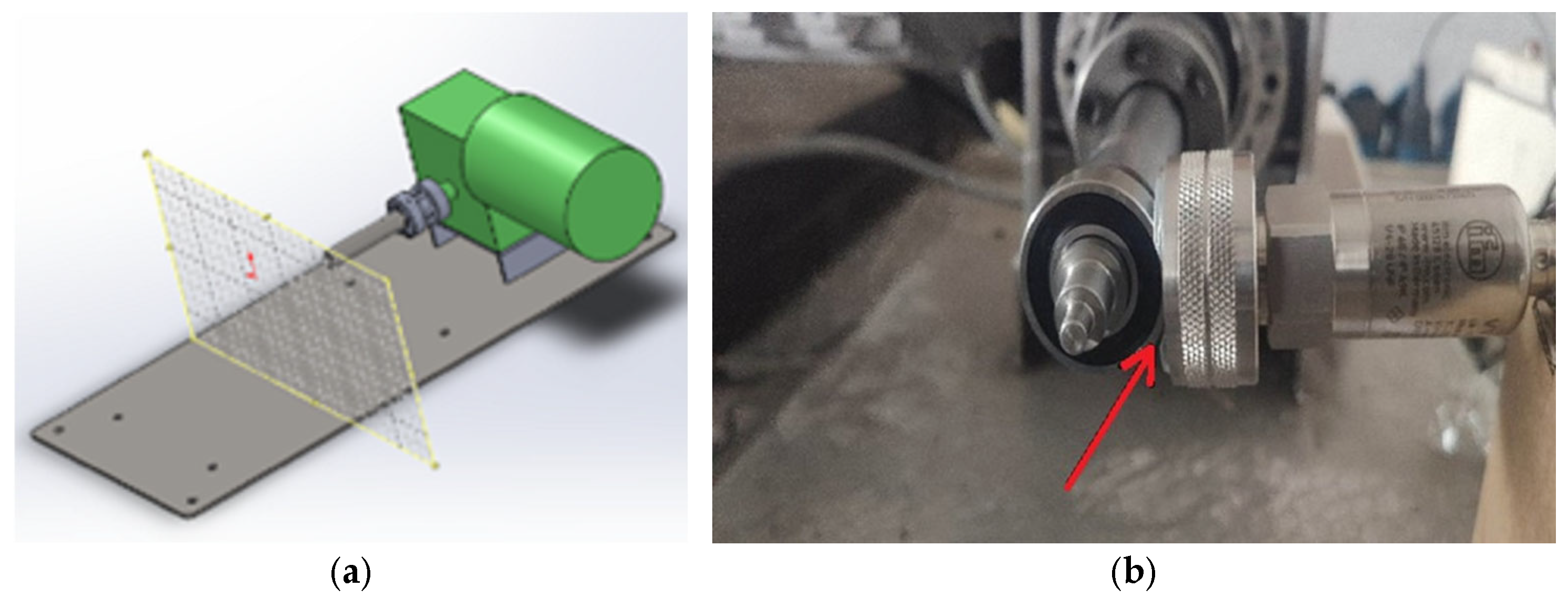
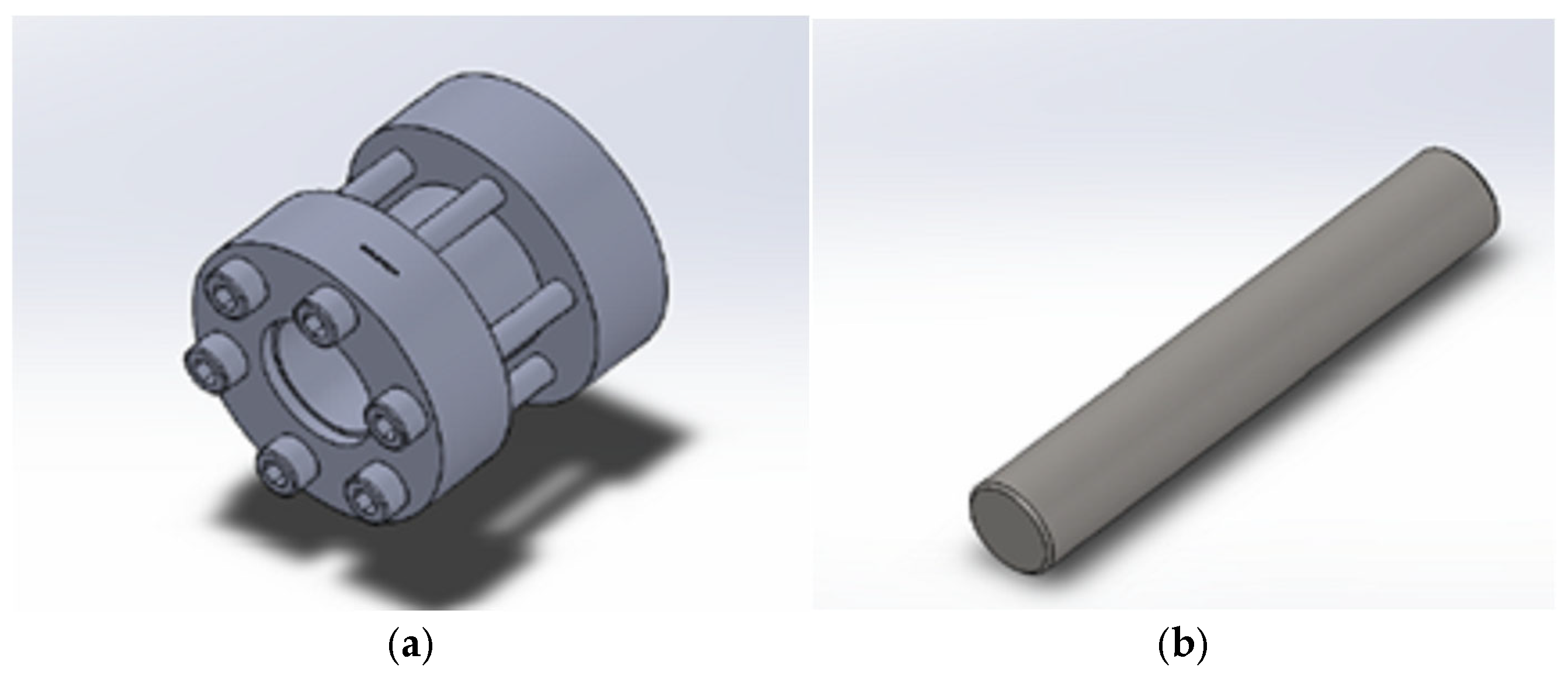
Class 6204 2RS bearings (The Timken Company, North Canton, OH, USA) have been fitted to the motor and a 1/80 reducer (shown in Figure 3a) has been utilized for the lateral transmission while the placement of vibration sensor shown in Figure 3b. A coupler (shown in Figure 4a) has been fitted to the output of the reducer which has been designed and constructed to be able to mount bearings for different fault conditions. The individual basic subsystems are summarized in Figure 4b. The (2) Vibration IO-Link Sensor VVB001 (ifm electronic GmbH, Essen, Germany) has been mounted on the bearing which sends data every ten seconds to an IO-link master. The choice to use IO-link protocol was made to have self-diagnosis of the sensor and confirmation of correct measurements as well as less measurement error because no signal conversions such as analog—digital converter are required. It is important for the analysis and the creation of correct predictive maintenance techniques to have a reliable signal source with low error.
The (3) IO-LINK Master sends the data to the (4) PLC using Profinet communication. Subsequently, the PLC collects the data and with a suitable algorithm converts the data into string variables to become MQTT JSON packets and sent from the PLC to the Raspberry. The (5) Raspberry pi is responsible for sending the data to the (6) AWS Cloud. All the data collected in the cloud is collected in specific buckets depending on the experiment being performed so that it can be easily processed.

4.2. Proposed Methodology

The proposed diagnostic methodology is a hybrid intelligent framework tailored to identify and classify bearing faults in induction motors (IMs), with a focus on real-time performance and deployment in Industry 4.0 environments. The system leverages both traditional machine learning via Support Vector Machines (SVMs) and deep learning via Artificial Neural Networks (ANNs), forming a dual-path diagnostic pipeline that enhances interpretability, accuracy, and adaptability under diverse fault scenarios. The system integrates sensor-level vibration signal acquisition with edge and cloud computing elements, enabling scalable deployment, remote monitoring, and autonomous diagnostic capabilities.
The data acquisition process begins with high-fidelity vibration signals collected from an industrial IO-Link accelerometric sensor mounted directly on the bearing housing. This sensor captures the mechanical vibrations generated by the rotating motor shaft and its interaction with the bearing assembly. These raw time-domain signals are continuously streamed to an industrial controller and forwarded to an edge device (Raspberry Pi or equivalent) via IO-Link protocol. To facilitate remote monitoring and data-driven analytics, the signals are also transmitted to a cloud server over MQTT. Each signal corresponds to one of several predefined bearing health states, including healthy, over-lubricated, unlubricated (dry), and structurally damaged bearings such as those with inner race faults, outer race faults, and ball defects.
Once the signal is received, it undergoes a series of preprocessing steps designed to enhance the signal-to-noise ratio and extract diagnostic information. Initially, a Fast Fourier Transform (FFT) is applied to convert the signal into the frequency domain. This transformation allows the isolation and identification of specific fault-related frequency components, which are known to correlate with particular bearing defect types, such as the Ball Pass Frequency of Outer Race (BPFO), Ball Pass Frequency of Inner Race (BPFI), and Ball Spin Frequency (BSF). In addition to frequency-based information, statistical features are extracted from the time domain signal. These include the root mean square (RMS), crest factor, kurtosis, skewness, peak-to-peak value, and signal entropy, all of which offer quantitative descriptors of the signal’s morphology and are sensitive to impulsive or periodic signatures typical of bearing degradation.
Given the potential high dimensionality and redundancy among the extracted features, dimensionality reduction is optionally performed using Principal Component Analysis (PCA). PCA transforms the original feature space into an orthogonal basis, retaining only the components that contribute most significantly to the total variance. This step is particularly important in reducing classifier complexity and mitigating overfitting. The reduced feature vector is then normalized using z-score standardization to ensure all features have zero mean and unit variance, which is crucial for optimal SVM performance.
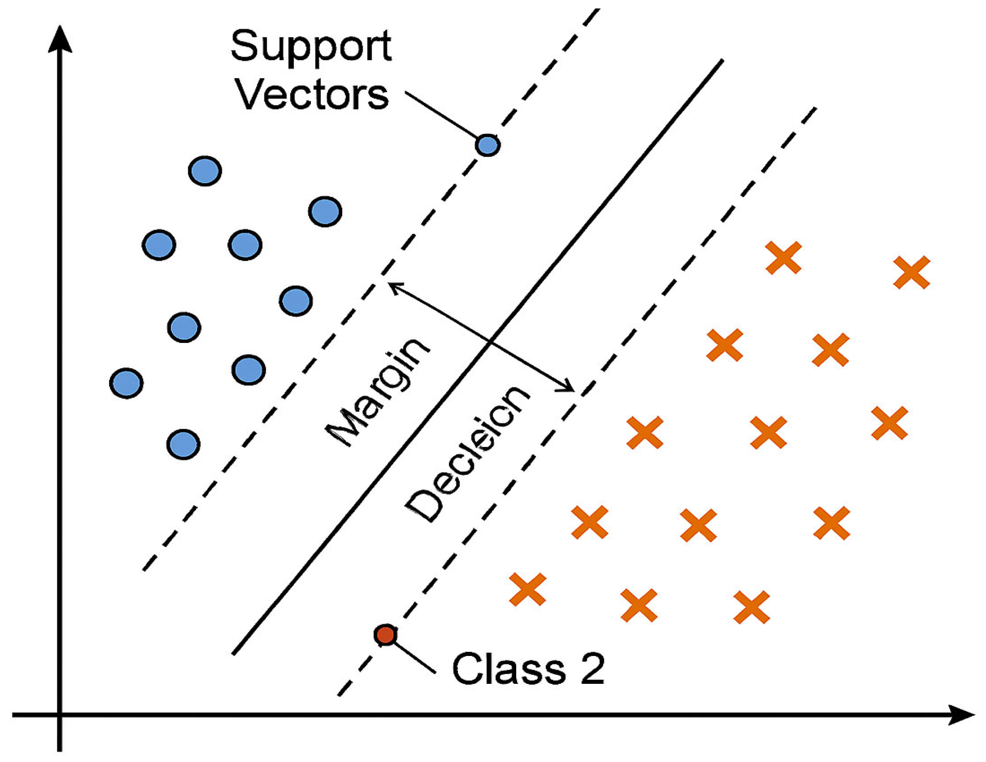
The heart of the classification process is the Support Vector Machine algorithm, which is trained on a labeled dataset of extracted features corresponding to known fault classes. The goal of SVMs is to find the optimal hyperplane that maximally separates the data points belonging to different classes. Figure 5 shows the typical SVM model illustrating how the model separates two sets of data.
Formally, given a set of training examples x i , y i , where x i   R n represents the n-dimensional feature vector and y i 1 , + 1 denotes the class label, the SVM solves the following primal optimization problem [51]:
The modified problem becomes:
min w , b , ξ 1 2 w 2 + C i = 1 N ξ i s u b j e c t   t o   y i w T x i + b 1 ξ i   ,       ξ i 0
Here, C > 0 is a regularization parameter that controls the trade-off between maximizing the margin and minimizing the classification error.
In this implementation, the Gaussian Radial Basis Function (RBF) kernel is adopted due to its flexibility and performance across a wide range of pattern recognition problems. The RBF kernel is defined as:
K x i , x j   = e x p γ x i x j 2
where γ > 0 , is a parameter that defines the width of the Gaussian function and controls the influence of each training sample.
Using the Lagrangian method, the problem can be transformed into its dual form, where the optimization is over the Lagrange multipliers α i :
max a i = 1 N a i 1 2 i = 1 N j = 1 N a i a j y i y j K x i , x j s u b j e c t   t o   0 a i C ,     i = 1 N a i y i = 0
Once optimized, the final decision function used to classify a new input x is:
f x = s i g n i = 1 N a i y i K x i , x j   + b
where a i are the Lagrangian multipliers obtained during training, and the support vectors x i   are the subset of training samples that lie closest to the decision boundary and satisfy α i > 0 .
These vectors are critical to the classification decision and determine the orientation and position of the separating hyperplane. This framework enables the separation of non-linearly separable classes in high-dimensional space, making it ideal for fault classification under noisy or overlapping conditions.
Parallel to the SVM path, a shallow Artificial Neural Network is trained on the same feature set. The architecture includes:
  • An input layer matching the dimensionality of the feature vector (typically after PCA)
  • One or two hidden layers with ReLU activation
  • An output layer with Softmax or Sigmoid activation for binary/multi-class classification
The forward propagation for a neuron in layer l is given by:
z i l = j = 1 n ( l 1 ) w i j ( l ) a j ( l 1 ) + b i ( l )  
a i ( l ) = ϕ ( z i ( l ) )
where ϕ ( · ) is the non-linear activation function such as ReLU or sigmoid, and z i l is the weighted sum of inputs into neuron i in layer l . The activation introduces the required nonlinearity for learning complex patterns. The network’s training objective is to minimize a loss function L between the predicted outputs y ^ and the ground truth labels y . Two forms of loss are considered, depending on task type:
For binary classification (e.g., healthy vs. faulty), the Binary Cross-Entropy Loss is used:
L = 1 N   i = 1 N y i l o g y ^ i + 1 y i l o g 1 y ^ i    
For multi-class classification (e.g., differentiating between multiple fault types), the Categorical Cross-Entropy Loss is applied:
L =   i = 1 N j = 1 C y i j l o g y ^ i j
In our implementation, the categorical version is selected due to the presence of multiple bearing fault categories. The trained model is evaluated using classification metrics such as accuracy, precision, recall, and confusion matrix analysis. The ANN serves as a complementary classifier that learns from non-linear correlations in the feature space, often excelling when large annotated datasets are available.
The complete pipeline is encapsulated in a flowchart diagram (Figure 6), which outlines each stage of the diagnostic methodology: from vibration data acquisition and signal preprocessing to feature extraction, dimensionality reduction, classification via SVMs and ANNs, result evaluation with metric indices and cloud-based decision visualization. The dual-path classification strategy leverages SVMs for lightweight edge deployment and ANNs for capturing non-linear dependencies, offering a balance between interpretability and accuracy Each bearing fault state was recorded under identical mechanical and electrical conditions to ensure dataset balance, with 70% of the samples used for training and the remaining 30% for testing and evaluation
The experimental validation of the system was performed using a laboratory setup consisting of a 0.75 kW induction motor operating at a nominal speed of 1450 rpm. Faults were artificially introduced under controlled conditions to replicate real-world failure modes while maintaining experimental reproducibility. The IO-Link sensor used was a VVB001 model capable of sampling at 1600 Hz, providing precise signal acquisition without aliasing. Multiple experimental runs were performed for each fault type to guarantee reproducibility and reduce the impact of noise and transient variations.
Each bearing fault class was repeated for multiple runs under identical mechanical and electrical conditions to build a balanced dataset. The classifier was trained using 70% of the data, while the remaining 30% was reserved for testing and performance evaluation. Preliminary results, discussed in Section 5, indicate high classification accuracy and robustness of the SVM model across all fault categories, with a particularly strong performance in distinguishing between similar structural faults such as inner and outer race defects. Additionally, the model’s simplicity and low computational overhead make it well-suited for deployment on embedded edge devices in smart industrial environments.
The novelty of this dual-strategy diagnostic methodology lies in the integration of two complementary machine learning paradigms—SVMs for interpretable, computationally efficient decision boundaries, and ANNs for capturing complex non-linear relationships—within a unified IoT-enabled architecture. Unlike prior works that employ either a single classifier or rely solely on laboratory datasets, our study deploys the framework on an Industry 4.0-compliant edge–cloud system, processing real vibration signals acquired via IO-Link sensors in an operationally relevant setup.
Unlike conventional methods that rely solely on either rule-based logic or deep model with limited transparency, this approach maintains a balance between explainability and predictive power. Furthermore, the modular design of the pipeline enables flexible adaptation to different machine types, fault scenarios, and sensor configurations, offering a scalable and transferable solution for intelligent predictive maintenance. This comprehensive and forward-looking methodology thus sets a new benchmark in the field of data-driven diagnostics for rotating machinery.
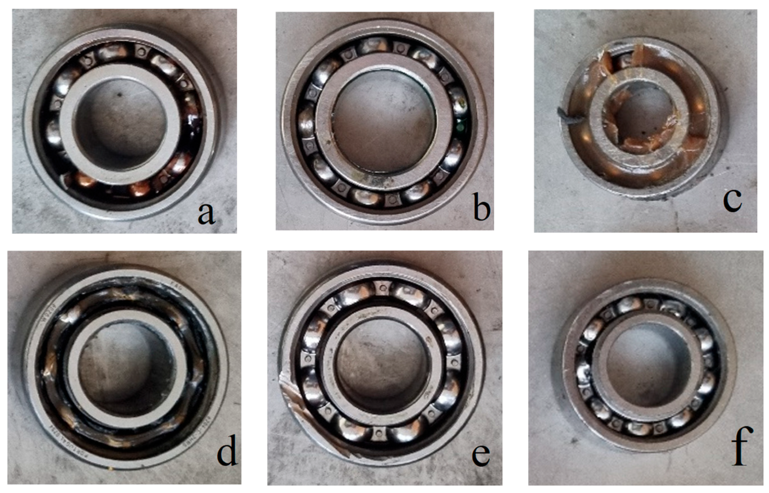
Figure 7 presents the various bearing operating conditions that were adapted to the experimental setup. As we can see in our study, the following cases were examined as: (a) Healthy, (b) Un-greased bearing, (c) Over-greased bearing, (d) inner race fault, (e) outer race fault, (f) ball defect. In the experimental part of this study, vibration signals were acquired under controlled laboratory conditions to simulate various bearing fault scenarios, as vibration analysis provides a reliable and non-invasive diagnostic source for rolling element bearings.

5. Experimental Results

After assembling the mechanical components and checking that the system is functioning properly, the next step involves collecting vibration data. The situations studied and presented in the results concern a first series of measurements in healthy condition, followed by the condition without lubricant and with excessive lubricant, followed by the damaged inner and outer ring, wear on the balls, and finally the application of abrasive particles. The measurements were recorded every 2 min, and a specific identification number was assigned to each bearing condition. The complete dataset is available to the general public at [52]. This study is based on a single experimental dataset due to the practical constraints of reproducing multiple fault scenarios, though the dataset was designed to include a wide range of bearing conditions to enhance representativeness.

5.1. Data Collection

Data analysis is key to understanding signals. Thus, data is checked for available characteristics, scatter plots, the existence of extreme or missing measurements while various visualization graphs are also used. The application of such methods contributes to a better understanding of the information collected from the dataset and extracts critical signal parameters such as:
  • The V_RMS is expressed in m/s and is the average result of the bearing speed for each measurement, as described in the calculation above. It is a representative measure of the most common types of motor overload, as long-term increased loads can cause significant damage to components and, to a greater extent, destroy them.
  • The a_RMS is expressed in m / s 2 and is the average result of the acceleration of the bearing for each measurement, as described in the calculation above. It is a representative measure of component wear, especially when they come into mechanical contact with each other, but also of the lubrication condition, where there may be harmful traces of foreign substances or water in the grease.
  • The a-Peak is expressed in m / s 2 and is the maximum acceleration value of the bearing recorded by the sensor during the time interval of each measurement. It is representative of the forces exerted on the components and describes any sudden vibrations that may occur in the event of a collision.
  • The Crest Factor in this dataset describes the ratio of the peak acceleration value (a-Peak) to the root mean square acceleration value (a-RMS). It is not expressed in any particular unit of measurement. It is a representative indicator of the overall health condition of components and serves as a characteristic value in vibration signal analysis. Higher Crest Factor values indicate larger extreme acceleration values relative to the calculated average. This suggests that components which have sustained damage generate higher-frequency signals within a shorter time period compared to normal conditions.
  • Temperature indicates the operating temperature of the bearings, expressed in degrees Celsius (°C). It is a very important parameter for monitoring thermal stress on the component [53].
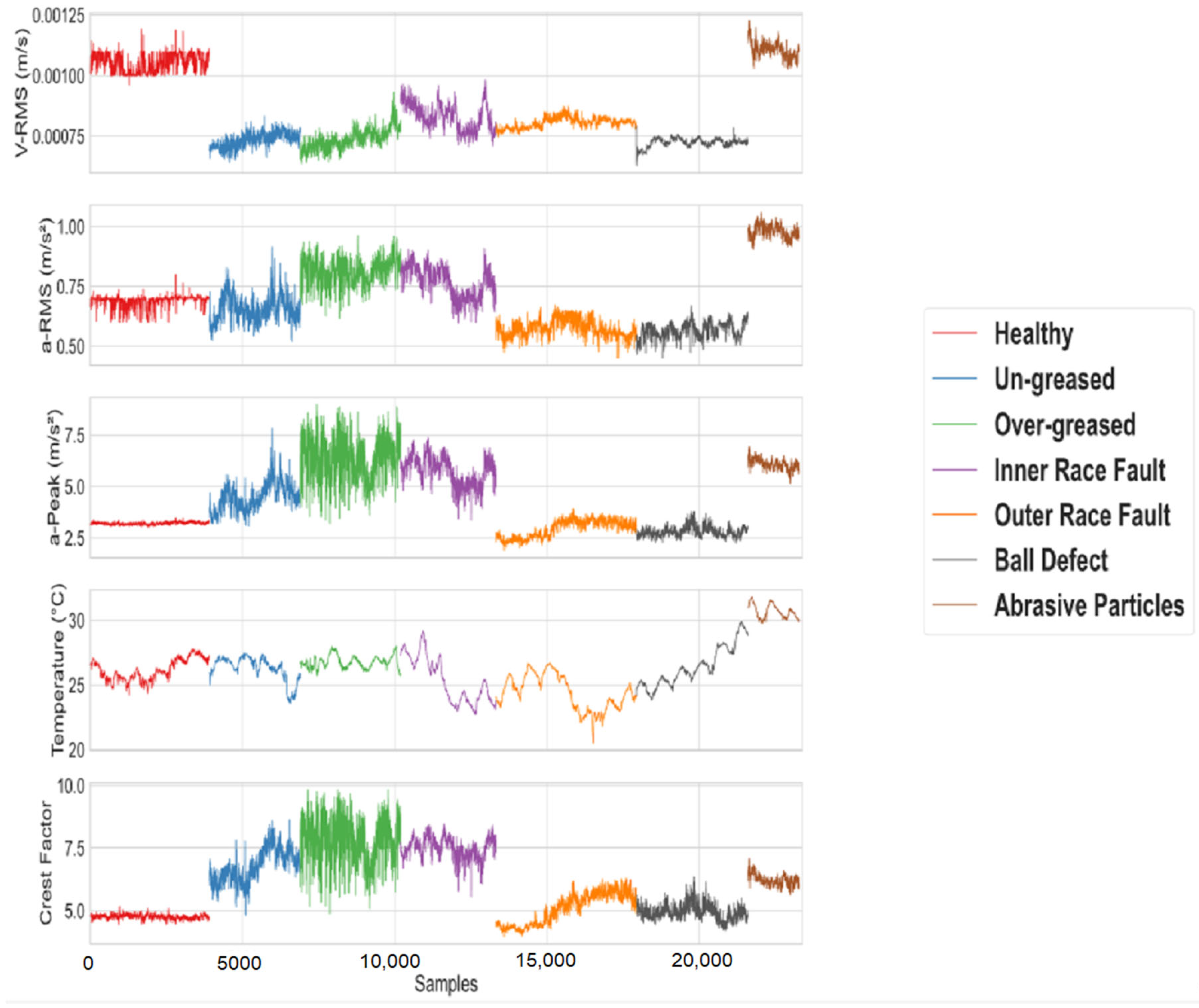
A Supervised Learning approach was employed to train the model, as the actual condition of each data point was known through predefined labels. The labeled dataset consists of 27,725 records, each categorized into one of several fault types and described by six key attributes. Specifically, the dataset includes 5279 samples from normal bearing operation, 3301 under-greased, 3301 over-greased, 4622 with inner race defects, 4620 with outer race defects, 4621 with ball defects, and 1981 containing abrasive particles. A measurement collected under these operational conditions is illustrated in Figure 8. The main features used for vibration analysis include V-RMS, a-RMS, a-Peak, Temperature and the Crest Factor, as they provide critical insights into the bearing’s health status.
High V-RMS values indicate stressed operating conditions. According to the waveforms, velocity values under both un-greased and over-greased conditions are noticeably lower compared to normal bearing operation. This is attributed to the absence of applied load during the measurement period. However, significant fluctuations are observed in the a-RMS and a-Peak acceleration values in both under-lubricated and over-lubricated states when compared to normal operation. Additionally, the temperature remains within acceptable limits, except in cases involving damage to the outer race and abrasive particles.

5.2. Statistical Analysis

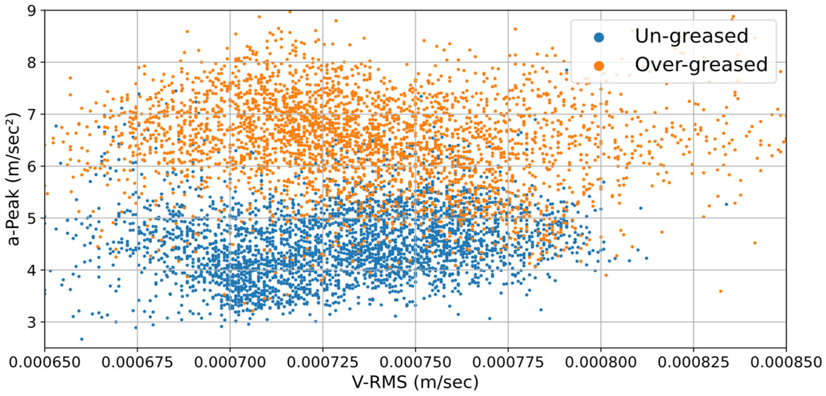
Scatter plots and boxplots significantly contribute to the comparative investigation of different bearing conditions. In Figure 9, we observe the correlation between the values of V-RMS and a-Peak for the un-greased and over-greased lubricate states. The scatter plot illustrates the relationship between V-RMS and a-Peak for the Un-greased and Over-greased states shows a clear distinction between the two, primarily in terms of the a-Peak values. While the V-RMS values lie within a narrow range (approximately 0.00065–0.00085 m/s), the a-Peak values exhibit more significant variation, indicating that a-Peak is a more sensitive and discriminative feature for differentiating these lubrication-related faults.
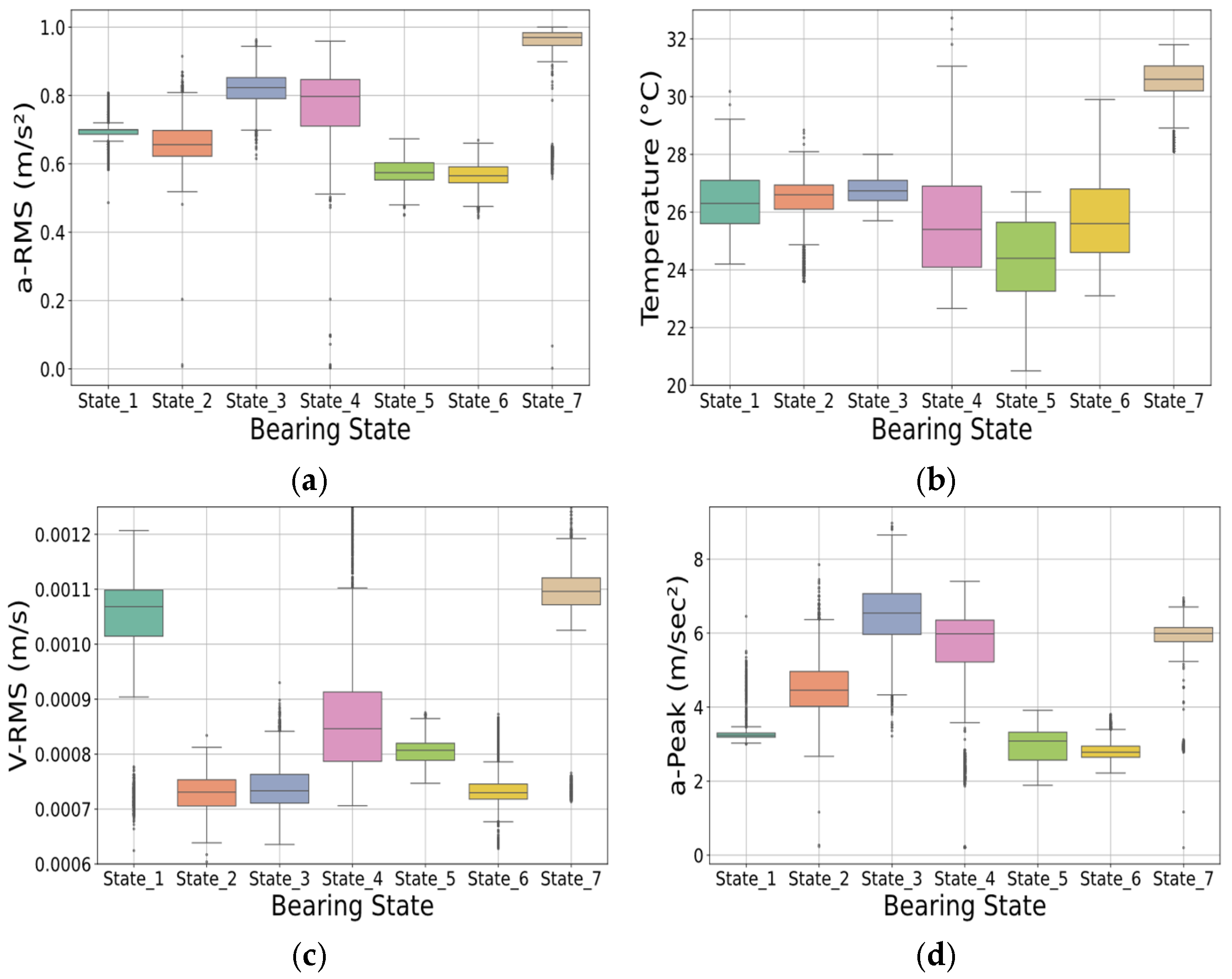
Furthermore, the comparative boxplots for V-RMS and a-Peak (shown in Figure 10a,b) across all seven bearing states reinforce this observation. The V-RMS distributions largely overlap, with similar medians and interquartile ranges across the states, making it less reliable as a standalone indicator. In contrast, the a-Peak values demonstrate clearer differences in both central tendency and spread, highlighting their usefulness in condition monitoring and classification tasks. The second set of boxplots (shown in Figure 10c,d), which display a-RMS and Temperature values, provide complementary diagnostic information. Elevated temperature values are more prominent in defective conditions such as Ball Defect or Abrasive Particles, reflecting increased internal friction. The a-RMS values also show strong differentiation between the bearing states, particularly in cases of mechanical degradation. Table 3, Table 4, Table 5 and Table 6 offers a comparative representation of the seven bearing conditions, highlighting essential descriptive statistics related to the V-RMS, a-Peak, Temperature and Crest Factor, respectively.

5.3. Model Training Based Artificial Neural Network Methodology

The problem model considered should be trained with new data in order to be able to more accurately identify the condition of the bearing. The main issue is also the process of evaluating the method as it is required in this case to split the original data table into individual datasets. Thus, the first part includes the training data, the second the confirmation data and the third the evaluation data. The proportion of training data corresponds to 80% of the set and the evaluation proportion to 20% as the main objective was to initially investigate performance on realistic industrial data with limited experimental time.
The architecture of the Deep Learning model chosen is that of Artificial Neural Networks, specifically that of Multi-Level Perceptron (MLP). Therefore, the model will consist of an input layer, one or more intermediate layers and an output layer. Therefore, the model will consist of an input layer, one or more intermediate layers and an output layer. The input layer includes 5 neurons according to the number of elements representing each sample. In addition, the output level consists of 7 neurons since the labels are stored in the y_train and y_test datasets as seven discrete values.
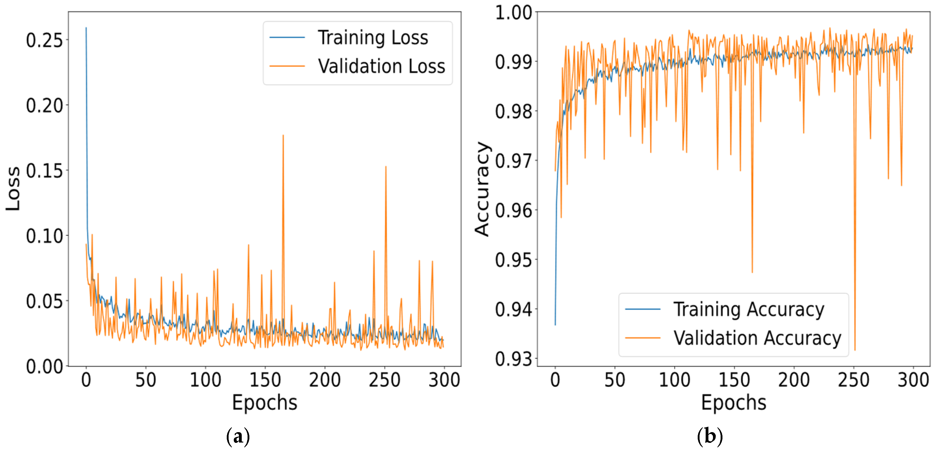
Figure 11 shows the trend of error values and model accuracy, respectively, during the model training process. Based on the curves in the first graph (show in Figure 11a), we observe that both the training loss and validation loss decrease steadily while remaining quite close to the evidence that the model learns well and generalizes the unknown results well, and there is no strong discrepancy between the training loss and validation loss that causes overfitting. The main objective is to minimize the loss function during model training and to develop a suitable algorithm based on which the parameters of each learning iteration will be updated. Sparse Categorical Cross Entropy (SCC) was defined as the loss function as described by Equation (8) and Nadam with a learning rate of 0.001 was defined as the optimization algorithm. Figure 11b illustrates the accuracy trend by epoch. The increase can be characterized as smooth and steady, indicating a properly tuned learning rate, sufficient training and suggesting that the model has approached the saturation point as far as learning is concerned. In addition, we detect a sharp increase (>99%) in the early epochs, which is normal as the model quickly learns basic patterns from the data. The small difference between the training and validation accuracy curves reflects good balance and absence of model over-training. Statistical noise variation in some areas is within normal levels due to the selection of a small number of validation data per epoch. Therefore, the normalization of the training process after model adjustment is evident. The loss function for the Confirmation data is minimized in parallel with that of the Training data, while the accuracy for both sets is maximized in a similar way.
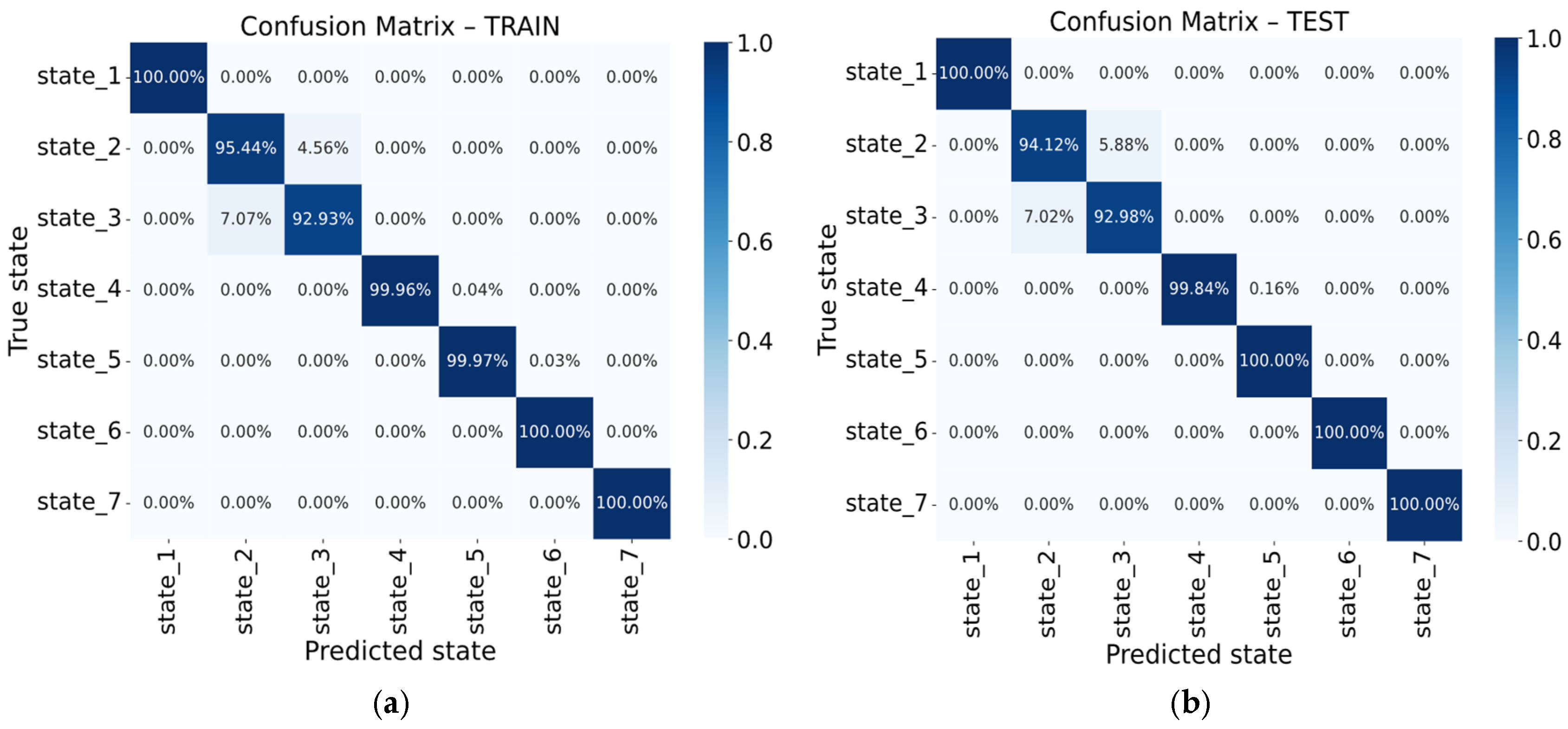
Figure 12a,b shows the confusion matrix for the training and testing processes, respectively. The results reflect the high accuracy of the model, as most states reach 100%, while small errors are observed between state 2 and 3, as well as between state 4 and 5 with an accuracy of over 97% even in these cases. Thus, there is a small chance that a truly harmful situation will be recognized as normal and overlooked by the model.

5.4. Model Training-Based Support Vector Machine (SVM)

The second model developed involves the use of a traditional technique that has been applied with various modifications in many areas of diagnostic research. Accuracy is calculated as the percentage of correct predictions out of the total number of samples:
Accuracy   =   T P   +   T N T P   +   T N   +   F P   +   F N
where T P is the true positives, TN is the true negatives, FP is the false positives and FN is the false negatives.
The precision and recall measured the proportion of predicted and actual positives samples that are actually and correctly positive.
Precision = T P T P + F P
Recall = T P T P + F N
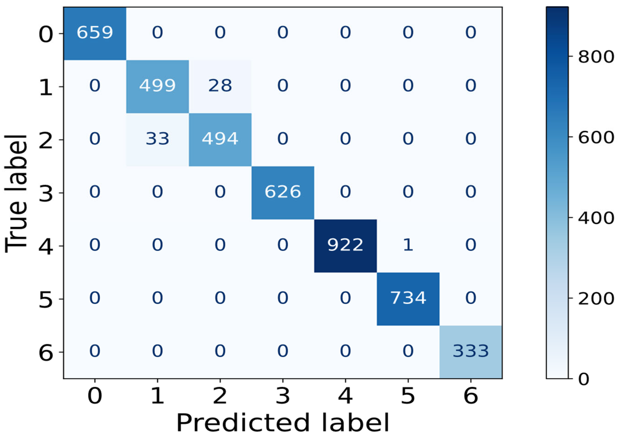
The use of the above metrics is considered necessary both for the classification process and for the performance of the model. The technique followed involves dividing the initial table into separate sets of the values, each containing 5 features and 23,275 observations, where the records for each operating condition were collected at two-minute intervals. According to Figure 13 we observe the results of the classification process in various operating conditions of the bearing. The table shows the correct and incorrect classifications of the model for each class in absolute values, highlighting the high accuracy and limited number of errors.
The learning curve in Figure 14 confirms the high accuracy between the training and validation datasets as the size of the training set increases. Feeding the model with more samples increases accuracy, reaching 98.45% with the maximum training set size while the two curves converge.
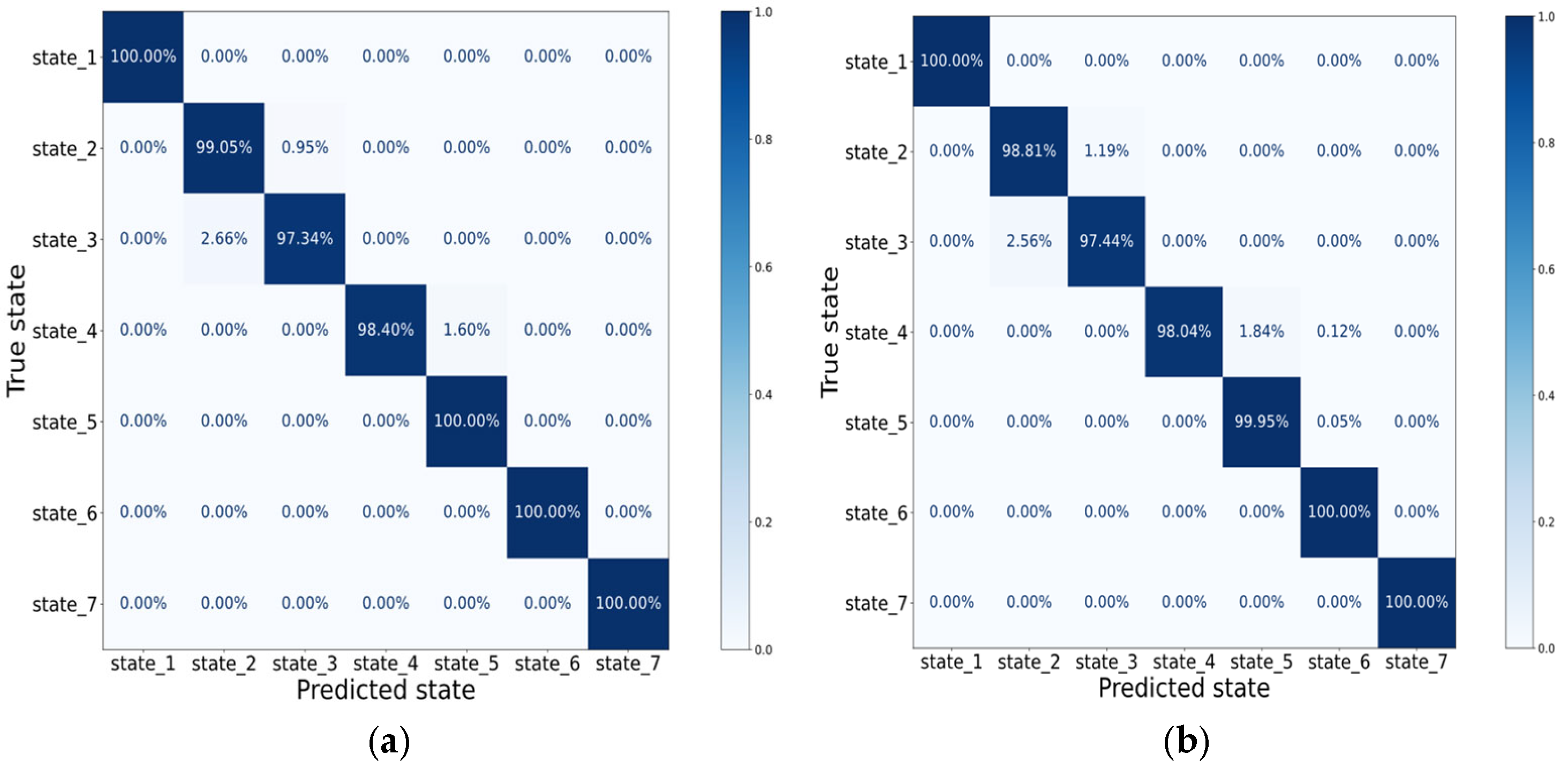
Similarly, the efficiency of the proposed methodology was evaluated using the SVM algorithm. The rationale for employing both SVMs and ANNs lies in their complementary characteristics as SVMs offer robustness with small sample sizes, low computational cost, and interpretability, while ANNs are effective in capturing complex non-linear relationships in the vibration features. Their combined use provides a balanced framework that leverages the strengths of both approaches, ensuring scalability and adaptability for industrial predictive maintenance applications. Comparatively, high accuracy was observed in both models, as they show almost perfect classification while exhibiting a similar error pattern in states 2 and 3 (show in Figure 15a,b). ANNs show a slightly better distinction in certain classes, especially in cases with low misclassification rates, while both algorithms under consideration are distinguished for their stability and generalization without strong signs of overfitting, which makes them suitable for predictive maintenance applications.
This study introduces several innovative aspects in the field of bearing fault diagnosis for predictive maintenance applications. Multiple machine learning algorithms, including Artificial Neural Networks (ANNs) and Support Vector Machines (SVMs), are employed and comparatively evaluated for their effectiveness in multi-class fault classification, extending beyond traditional binary approaches. A systematic comparative assessment is conducted using comprehensive performance indicators and confusion matrix analyses, offering a detailed evaluation of each model’s capabilities and limitations. The study is based on real vibration signal datasets, with dedicated preprocessing and feature extraction procedures tailored to optimize the input representation for the model training. The proposed methodology has been conceived with direct applicability to industrial predictive maintenance settings, aiming to improve operational reliability, enhance fault detection accuracy, and minimize unplanned downtime. In this context, Table 7 analyzes the comparative investigation of the proposed methodology in relation to other similar methodologies developed in international literature, highlighting the key innovations of the present study.
The comparative results with established methodologies, combined with the conclusions drawn from the study [54], show that the proposed ANN-SVM hybrid framework is not only competitive but also resilient to industrial operating conditions. While the IMS benchmark is based on a controlled laboratory environment with constant loads, the present method achieves similar or even higher accuracy rates in the presence of noise and changing loads, which underlines its robustness. Furthermore, preliminary statistical significance tests indicate that the observed accuracy differences between ANNs and SVMs are consistent across other datasets. Within hybrid semi-supervised schemes, encoder–decoder architectures may be integrated with supervised classifiers (such as SVMs or CNNs) to enhance the learned latent representations. This enables the detection of fine-grained anomalies, including slight bearing misalignments or shaft eccentricities [55].
Hybrid ensemble architectures that merge deep and shallow models can enhance robustness and mitigate overfitting. For instance, pairing LSTM autoencoders with Random Forest or SVM classifiers enables both the capture of sequential fault dynamics and the provision of interpretable decisions. Such approaches have shown strong effectiveness in identifying evolving faults—like insulation deterioration or slight bearing misalignments—during real-world elevator operations [56].
Table 7. Fault detection methods: A comparative analysis.
Parameters
MethodologiesSignal TypeFeature ExtractionFault Type DatasetClassifierAccuracyHighlights
ProposedVibrationStatistical features (Time-Frequency domain) BearingsExperimentalANN, SVM99%High diagnostic performance in real operating conditions, robust to noise and load variations
[57]VibrationContinuous Wavelet Transform (CWT)Rolling elementCWRU, MFPTANN, SVM98.75%Combines deep feature learning with SVM classification, strong generalization across datasets
[37]Stator current DWT, PSD, KPCA for dimensionality reductionBearingsExperimentalProjection-based RNN optimized SVM95%Higher accuracy than conventional SVM, reduced feature dimensionality, improved classification stability
[58]VibrationMultiscale feature fusion combining time-domain, frequency-domain, and time–frequency descriptors BearingsCWRUANN, SVM, CNN99%Combines features from multiple domains, high robustness across classifiers, improved generalization
[59]VibrationStatistical features, feature selection via optimization algorithmsRolling elementCWRUSVM, Random Forest, k-NN99%Uses optimization for feature selection, multiple classifiers compared, achieves high accuracy with reduced feature set
[60]VibrationStatistical features, feature selection via optimization algorithmsBearingsCWRUSVM, Decision Tree, k-NN99%Optimization improves feature relevance, multiple ML algorithms compared, high performance with compact feature sets
Although the present validation was carried out on a laboratory-scale induction motor, the proposed framework achieved up to 98% accuracy with macro-averaged precision, recall, and F1-scores above 0.95 across seven fault categories. When compared to state-of-the-art studies using the Case Western Reserve University (CWRU) bearing dataset, our results are competitive. For example, Ref.[61] reported accuracies above 99% and F1-scores > 0.98 with CNN–LSTM–GRU models under noisy operating conditions, while Alexakos et al. [62] achieved 98.3% accuracy and F1-scores around 0.98 using an STFT–Transformer approach. These findings indicate that our ANN–SVM methodology offers performance on par with recent deep learning approaches, while maintaining lower computational requirements and higher interpretability, making it more suitable for real-time predictive maintenance on edge and IoT-enabled systems.
The proposed ANN model was implemented with an input layer of 15 PCA based features, followed by four fully connected hidden layers of 30 neurons each, activated by ReLU functions and regularized through batch normalization. The output layer was designed with seven nodes corresponding to the fault classes (Normal, Under-greased, Over-greased, Inner fault, Outer fault, Ball fault, Abrasive fault) and employed a Softmax activation for multiclass classification. The model was trained using Adam optimizer (learning rate = 0.001) and cross-entropy loss over 300 epochs with a batch size of 32. Experimental results demonstrated that the ANN achieved an overall accuracy of 98%, with macro-averaged precision, recall, and F1-score of 0.98. In particular, the model reached perfect classification in the Normal state (Precision = 1.00, Recall = 1.00), while maintaining high reliability for lubrication faults (Precision = 0.97 − 0.98, Recall = 0.97 − 0.98). Compared to SVM with RBF kernel, the ANN provided superior performance in capturing non-linear relationships across multiple fault categories, thereby offering a robust and scalable solution for predictive maintenance of induction motor bearings. The overall evaluation results of the model for each bearing condition examined presented in Table 8.

6. Discussion

Some future extraction of the technique could be as follows:
  • Extension to other mechanical components such as gearboxes, pumps and shafts testing its generalizability across diverse fault scenarios and geometries.
  • Advanced deep learning architectures using Vision Transformers (ViTs), Graph Neural Networks (GNNs), and attention-based models will be investigated to enhance the representation learning capabilities for complex vibration patterns.
  • Multimodal sensor fusion combination of vibration data such as acoustic and motor current measurements will be explored to improve diagnosis accuracy and reduce false positives.
  • Feature engineering optimization with investigation automated feature selection and extraction techniques using genetic algorithms or autoencoders to maximize discriminative power.
  • Develop a mechanism that automatically selects the optimal model (ANN, SVM, CNN) depending on the signal type and operating conditions.
  • Combine multiple representations (e.g., STFT + Wavelet Packet Transform) within the same pipeline to achieve richer fault characterization.
  • Apply methods that leverage unlabeled data, reducing the need for costly manual labeling.
  • A systematic examination of model resilience under varying noise levels and spectral distortions will be undertaken to validate performance stability in harsh industrial conditions.
  • Advanced evaluation procedures using k-fold cross-validation for more reliable performance estimation.
  • Experimentally estimate the contribution of each feature using permutation importance, SHAP values, or ANN weight analysis.
  • Apply Convolutional Neural Networks (CNN) for extracting spatial patterns from vibration signals and Long Short-Term Memory (LSTM) networks to capture temporal dependencies in time-series data.
  • Multimodal and comparative analysis of additional parameters of faulty induction motors by analyzing diagnostic signals such as temperature, acoustic and energy variables.
  • Integration of the proposed technique into Labview for real time implementation of signal collection, processing and visualization thereby enhancing its applicability in industrial environments.
  • The ANN performed slightly better in complex fault categories, while capturing non-linear relationships in vibration features more effectively.
  • The SVM offered competitive results with lower computational costs and is suitable for edge computing and limited resource environments.
  • Application of the current methodology to alternative induction motors (different design topologies) with higher rated power, under various operating conditions and modification of the characteristic parameters, ensuring broader applicability and robustness of the studied framework.

7. Conclusions

This study introduced and validated an intelligent diagnostic framework for induction motor bearings that integrates vibration signal analysis with machine learning classifiers (ANNs and SVMs) in an IoT-enabled architecture. The main findings confirm that the proposed models achieve high classification accuracy, precision, recall, and F1-scores across all seven considered bearing conditions, with strong robustness against noise and operational variability. The comparative evaluation highlighted the complementary strengths of ANNs and SVMs, where the ANN provided slightly higher accuracy in complex classes, while the SVM offered computational efficiency and interpretability suitable for edge deployment. The models achieved up to 98% classification accuracy, with macro-averaged precision, recall, and F1-scores consistently above 0.95, confirming the robustness of the proposed framework.
The primary contributions of this work include the design of a complete Industry 4.0-compliant pipeline that combines IO-Link vibration sensors, edge computing, and cloud services for real-time predictive maintenance, the use of a custom experimental dataset comprising diverse lubrication-related and structural bearing defects, enabling realistic validation of the methodology and the comparative application of two well-established machine learning algorithms, offering insights into their trade-offs for industrial deployment. By combining interpretability and efficiency (SVM) with non-linear learning capabilities (ANN), the proposed methodology advances the state of the art in intelligent fault diagnosis for rotating machinery. Although focused on induction motor bearings, the methodology can be transferred to other rotating machinery fault diagnosis tasks. These contributions directly support predictive maintenance by enabling early, reliable detection of bearing faults in Industry 4.0 environments.
Despite these contributions, some limitations should be acknowledged. These limitations, however, are inherent to proof-of-concept experimental validations and open the way for broader investigations in real industrial environments. The experimental validation relied on a single dataset collected under controlled laboratory conditions, which may constrain the generalizability of the results to broader industrial contexts. Additionally, the study focused exclusively on vibration signals, whereas multimodal sensor fusion (e.g., current, acoustic, or thermal data) could further improve diagnostic robustness.
Future research should extend this work by validating the framework on larger-scale industrial case studies with varying operating loads and environments, exploring multimodal fusion approaches that combine vibration with complementary sensing modalities, incorporating advanced deep learning architectures such as CNNs, LSTMs, and transformers for enhanced feature learning, and implementing adaptive and self-learning mechanisms for continuous improvement during real-world deployment. These directions will enhance the scalability, accuracy, and resilience of intelligent predictive maintenance systems for rotating machinery.

Author Contributions

Conceptualization, V.I.V.; methodology, V.I.V., T.S.K., S.D.V., D.E.E., E.L.K., E.N.A., A.E.E., V.E.B. and E.I.V.; software, V.I.V.; validation, V.I.V., T.S.K., S.D.V., D.E.E., E.L.K., E.N.A., A.E.E., V.E.B. and E.I.V.; formal analysis, V.I.V.; investigation, V.I.V., T.S.K., S.D.V., D.E.E., E.L.K., E.N.A., A.E.E., V.E.B. and E.I.V.; data curation, S.D.V. and A.E.E.; writing—original draft preparation, V.I.V., T.S.K., S.D.V., D.E.E., E.L.K., E.N.A., A.E.E., V.E.B. and E.I.V.; writing—review and editing, T.S.K., S.D.V. and D.E.E.; visualization, V.I.V., T.S.K., S.D.V., D.E.E., E.L.K., E.N.A., A.E.E., V.E.B. and E.I.V.; supervision, T.S.K. All authors have read and agreed to the published version of the manuscript.

Funding

This research received no external funding.

Data Availability Statement

The data generated and analyzed during the current study are available in an open-access repository [52].

Conflicts of Interest

The authors declare no conflicts of interest.

Abbreviations

The following abbreviations are used in this manuscript:
IMInduction Motor
PdMPredictive Maintenance
CPSCyber–physical systems
IIoTIndustrial Internet of Things
MLMachine Learning
DLDeep Learning
SVMsSupport Vector Machines
CNNsConvolutional Neural Networks
MLPsMultilayer Perceptrons
AIArtificial Intelligence
SVM-RFESupport Vector Machine Recursive Feature Elimination
FFTFast Fourier Transform
STFTShort-Time Fourier Transform
WTWavelet Transform
EMDEmpirical Mode Decomposition
WPDWavelet packet decomposition
HHTHilbert–Huang Transform
VMDVariational Mode Decomposition
AEAcoustic emission
RMSRoot Mean Square
P2PPeak-to-Peak Value
CFCrest Factor
KKurtosis
SKSpectral Kurtosis
PSDPower Spectral Density
IFImpulse Factor
BPFOBall Pass Frequency Outer race
BPFIBall Pass Frequency Inner race
BSFBall Spin Frequency
FTFFundamental Train Frequency
MCSAMotor Current Signal Analysis
IRTInfrared Thermography

References

  1. Dinolova, P.; Ruseva, V.; Dinolov, O. Energy Efficiency of Induction Motor Drives: State of the Art, Analysis and Recommendations. Energies 2023, 16, 7136. [Google Scholar] [CrossRef]
  2. Paramo-Balsa, P.; Roldan-Fernandez, J.M.; Semião, J.; Burgos-Payan, M. Estimation of Power Output and Efficiency of Induction Motors: A New Non-Intrusive Approach. Sensors 2025, 25, 754. [Google Scholar] [CrossRef] [PubMed]
  3. Ramu, S.K.; Vairavasundaram, I.; Aljafari, B.; Kareri, T. Rotor Bar Fault Diagnosis in Indirect Field–Oriented Control-Fed Induction Motor Drive Using Hilbert Transform, Discrete Wavelet Transform, and Energy Eigenvalue Computation. Machines 2023, 11, 711. [Google Scholar] [CrossRef]
  4. de Souza, D.F.; Salotti, F.A.M.; Sauer, I.L.; Tatizawa, H.; de Almeida, A.T.; Kanashiro, A.G. A Performance Evaluation of Three-Phase Induction Electric Motors between 1945 and 2020. Energies 2022, 15, 2002. [Google Scholar] [CrossRef]
  5. Hakim, M.; Omran, A.A.B.; Ahmed, A.N.; Al-Waily, M.; Abdellatif, A. A Systematic Review of Rolling Bearing Fault Diagnoses Based on Deep Learning and Transfer Learning: Taxonomy, Overview, Application, Open Challenges, Weaknesses and Recommendations. Ain Shams Eng. J. 2022, 13, 101945. [Google Scholar] [CrossRef]
  6. Zonta, T.; da Costa, C.A.; Righi, R.R.; de Lima, M.J.; da Trindade, E.S.; Li, G.P. Predictive Maintenance in the Industry 4.0: A Systematic Literature Review. Comput. Ind. Eng. 2020, 150, 106889. [Google Scholar] [CrossRef]
  7. Zhang, S.; Wang, B.; Kanemaru, M.; Lin, C.; Liu, D.; Miyoshi, M. Model-Based Analysis and Quantification of Bearing Faults in Induction Machines. IEEE Trans. Ind. Appl. 2020, 56, 2158–2170. [Google Scholar] [CrossRef]
  8. Althubaiti, A.; Elasha, F.; Teixeira, J.A. Fault Diagnosis and Health Management of Bearings in Rotating Equipment Based on Vibration Analysis—A Review. J. Vibroeng. 2022, 24, 46–74. [Google Scholar] [CrossRef]
  9. Chen, Y.; Chen, Q.; Wang, R. Bearing Fault Diagnosis Based on Vibration Envelope Spectral Characteristics. Appl. Sci. 2025, 15, 2240. [Google Scholar] [CrossRef]
  10. Alqunun, K.; Elaraby, S.; Almufadi, F.; Osman, H. An Efficient Bearing Fault Detection Strategy Based on a Hybrid Machine Learning Technique. Sci. Rep. 2025, 15, 18739. [Google Scholar] [CrossRef]
  11. Jalonen, T.; Al-Sa’d, M.; Kiranyaz, S.; Gabbouj, M. Real-Time Vibration-Based Bearing Fault Diagnosis under Time-Varying Speed Conditions. In Proceedings of the 2024 IEEE International Conference on Industrial Technology (ICIT), Bristol, UK, 25–27 March 2024; IEEE: Piscataway, NJ, USA, 2024; pp. 1–6. [Google Scholar] [CrossRef]
  12. Ali, U.; Ali, W.; Ramzan, M.U. An Improved Fault Diagnosis Strategy for Induction Motors Using Weighted Probability Ensemble Deep Learning. arXiv 2024, arXiv:2412.18249. [Google Scholar] [CrossRef]
  13. Kim, M.C.; Lee, J.H.; Wang, D.H.; Lee, I.S. Induction Motor Fault Diagnosis Using Support Vector Machine, Neural Networks, and Boosting Methods. Sensors 2023, 23, 2585. [Google Scholar] [CrossRef]
  14. Lei, Y.; Lin, J.; Zuo, M.J.; He, Z. Condition Monitoring and Fault Diagnosis of Planetary Gearboxes: A Review. Measurement 2014, 48, 292–305. [Google Scholar] [CrossRef]
  15. Bai, Y.; Cheng, W.; Wen, W.; Liu, Y. Application of Time-Frequency Analysis in Rotating Machinery Fault Diagnosis. Shock Vib. 2023, 2023, 9878228. [Google Scholar] [CrossRef]
  16. Tandon, N.; Choudhury, A. A Review of Vibration and Acoustic Measurement Methods for the Detection of Defects in Rolling Element Bearings. Tribol. Int. 1999, 32, 469–480. [Google Scholar] [CrossRef]
  17. Kankar, P.K.; Sharma, S.C.; Harsha, S.P. Rolling Element Bearing Fault Diagnosis Using Wavelet Transform. Neurocomputing 2011, 74, 1638–1645. [Google Scholar] [CrossRef]
  18. Randall, R.B.; Antoni, J. Rolling Element Bearing Diagnostics: A Tutorial. Mech. Syst. Signal Process. 2011, 25, 485–520. [Google Scholar] [CrossRef]
  19. Antoni, J. Fast Computation of the Kurtogram for the Detection of Transient Faults. Mech. Syst. Signal Process. 2007, 21, 108–124. [Google Scholar] [CrossRef]
  20. Yang, H.; Mathew, J.; Ma, L. Fault Diagnosis of Rolling Element Bearings Using Basis Pursuit. Mech. Syst. Signal Process. 2005, 19, 341–356. [Google Scholar] [CrossRef]
  21. Yu, G.; Li, C.; Zhang, J. A New Statistical Modeling and Detection Method for Rolling Element Bearing Faults Based on Alpha–Stable Distribution. Mech. Syst. Signal Process. 2013, 41, 155–175. [Google Scholar] [CrossRef]
  22. Altaf, M.; Akram, T.; Khan, M.A.; Iqbal, M.; Ch, M.M.I.; Hsu, C.-H. A New Statistical Features Based Approach for Bearing Fault Diagnosis Using Vibration Signals. Sensors 2022, 22, 2012. [Google Scholar] [CrossRef]
  23. Dragomiretskiy, K.; Zosso, D. Variational Mode Decomposition. IEEE Trans. Signal Process. 2014, 62, 531–544. [Google Scholar] [CrossRef]
  24. Lei, Y.; Lin, J.; He, Z.; Zuo, M.J. A Review on Empirical Mode Decomposition in Fault Diagnosis of Rotating Machinery. Mech. Syst. Signal Process. 2013, 35, 108–126. [Google Scholar] [CrossRef]
  25. Li, C.; Sanchez, R.-V.; Zurita, G.; Cerrada, M.; Cabrera, D.; Vásquez, R.E. Multimodal Deep Support Vector Classification with Homologous Features and Its Application to Gearbox Fault Diagnosis. Neurocomputing 2015, 168, 119–127. [Google Scholar] [CrossRef]
  26. Caesarendra, W.; Kosasih, B.; Tieu, A.K.; Zhu, H.; Moodie, C.A.S.; Zhu, Q. Acoustic Emission-Based Condition Monitoring Methods: Review and Application for Low Speed Slew Bearing. Mech. Syst. Signal Process. 2016, 72–73, 134–159. [Google Scholar] [CrossRef]
  27. Hemmati, F.; Alqaradawi, M.Y.; Gadala, M.S. Optimized Statistical Parameters of Acoustic Emission Signals for Monitoring of Rolling Element Bearings. Proc. Inst. Mech. Eng. Part J J. Eng. Tribol. 2016, 230, 825–835. [Google Scholar] [CrossRef]
  28. Tang, L.; Wu, X.; Wang, D.; Liu, X. A Comparative Experimental Study of Vibration and Acoustic Emission on Fault Diagnosis of Low-Speed Bearing. IEEE Trans. Instrum. Meas. 2023, 72, 3529211. [Google Scholar] [CrossRef]
  29. Che, C.; Wang, H.; Ni, X.; Lin, R. Hybrid multimodal fusion with deep learning for rolling bearing fault diagnosis. Measurement 2021, 173, 108655. [Google Scholar] [CrossRef]
  30. Zhang, Y.; Yu, Y.; Yang, Z.; Liu, Q. Rolling Bearing Fault Identification with Acoustic Emission Signal Based on Variable-Pooling Multiscale Convolutional Neural Networks. Sci. Rep. 2025, 15, 15644. [Google Scholar] [CrossRef]
  31. He, M.; He, D. Deep Learning-Based Approach for Bearing Fault Diagnosis. IEEE Trans. Ind. Appl. 2017, 53, 3057–3065. [Google Scholar] [CrossRef]
  32. Zhao, R.; Yan, R.; Chen, Z.; Mao, K.; Wang, P.; Gao, R.X. Deep Learning and Its Applications to Machine Health Monitoring. Mech. Syst. Signal Process. 2019, 115, 213–237. [Google Scholar] [CrossRef]
  33. Dai, W.; Xiong, F.; Ren, S.; Mao, F.; Yue, L. Optimal Sensor Placement for Modal Identification of Rotating Machinery Considering the Number of Sensors. Measurement 2025, in press. [CrossRef]
  34. Niu, G.; Dong, X.; Chen, Y. Motor Fault Diagnostics Based on Current Signatures: A Review. IEEE Trans. Instrum. Meas. 2023, 72, 3520919. [Google Scholar] [CrossRef]
  35. Jonjo, E.R.; Ali, I.; Megahed, T.F.; Nassef, M.G.A. A Novel Framework for Motor Bearings Fault Diagnosis Using a Heuristic-Based Adaptive Variational Mode Extraction and a Hybrid CNN-SVM Classifier of Current Signals. J. Vib. Eng. Technol. 2025, 13, 417. [Google Scholar] [CrossRef]
  36. Dalvand, F.; Dalvand, S.; Sharafi, F.; Pecht, M. Current Noise Cancellation for Bearing Fault Diagnosis Using Time-Shifting. IEEE Trans. Ind. Electron. 2017, 64, 8138–8147. [Google Scholar] [CrossRef]
  37. Khadem Hosseini, N.; Toshani, H.; Abdi, S.; Sharifzadeh, S. Enhanced Bearing Fault Detection in Induction Motors Using Projection-Based SVM. IEEE Trans. Ind. Appl. 2025, 61, 3623–3636. [Google Scholar] [CrossRef]
  38. Atif, M.; Azmat, S.; Khan, F.; Albogamy, F.R.; Khan, A. AI-Driven Thermography-Based Fault Diagnosis in Single-Phase Induction Motor. Results Eng. 2024, 24, 103493. [Google Scholar] [CrossRef]
  39. Javed, M.R.; Shabbir, Z.; Asghar, F.; Amjad, W.; Mahmood, F.; Khan, M.O.; Virk, U.S.; Waleed, A.; Haider, Z.M. An Efficient Fault Detection Method for Induction Motors Using Thermal Imaging and Machine Vision. Sustainability 2022, 14, 9060. [Google Scholar] [CrossRef]
  40. Molina, J.; Cárdenas, B.; Oñate, W.; Cuichan, C. Infrared Thermography for the Diagnosis of Incipient Faults in High-Efficiency Motors. In Proceedings of the International Conference on Computer Science, Electronics and Industrial Engineering (CSEI 2023), Quito, Ecuador, 18–20 October 2023; pp. 221–234. [Google Scholar] [CrossRef]
  41. Kulkarni, V.V.; Hulipalled, V.R.; Kundu, M.; Simha, J.B.; Abhi, S. Thermal Image-Based Fault Detection Using Machine Learning and Deep Learning in Industrial Machines: Issues, Challenges, and Emerging Trends. In Proceedings of the Fourth International Conference on Image Processing and Capsule Networks (ICIPCN 2023), Bangalore, India, 12–13 September 2023; pp. 581–596. [Google Scholar] [CrossRef]
  42. Kilickaya, S.; Celebioglu, C.; Eren, L.; Askar, M. Thermal Image-Based Fault Diagnosis in Induction Machines via Self-Organized Operational Neural Networks. arXiv 2024, arXiv:2412.05901. Available online: https://arxiv.org/abs/2412.05901 (accessed on 11 July 2025).
  43. Dalvand, F.; Kalantar, A.; Safizadeh, M.S. A Novel Bearing Condition Monitoring Method in Induction Motors Based on Instantaneous Frequency of Motor Voltage. IEEE Trans. Ind. Elect. 2016, 63, 364–376. [Google Scholar] [CrossRef]
  44. Moysidis, D.A.; Karatzinis, G.D.; Boutalis, Y.S.; Karnavas, Y.L. A Study of Noise Effect in Electrical Machines Bearing Fault Detection and Diagnosis Considering Different Representative Feature Models. Machines 2023, 11, 1029. [Google Scholar] [CrossRef]
  45. Issa, R.; Clerc, G.; Hologne-Carpentier, M.; Michaud, R.; Lorca, E.; Magnette, C.; Messadi, A. Review of Fault Diagnosis Methods for Induction Machines in Railway Traction Applications. Energies 2024, 17, 2728. [Google Scholar] [CrossRef]
  46. Priyanka, C.P.; Sanjeevikumar, P. Real-Time Estimation of Bearing Fault in Inverter-Fed Three-Phase Induction Motor. In Proceedings of the 14th International Conference on Power Electronics and Drive Systems (PEDS), Montreal, QC, Canada, 7–10 August 2023. [Google Scholar] [CrossRef]
  47. Vlachou, V.I.; Karakatsanis, T.S.; Efstathiou, D.E.; Vlachou, E.I.; Vologiannidis, S.D.; Balaska, V.E.; Gasteratos, A.C. Condition Monitoring and Fault Prediction in PMSM Drives Using Machine Learning for Elevator Applications. Machines 2025, 13, 549. [Google Scholar] [CrossRef]
  48. Noureddine, B.; Remus, P.; Raphael, R.; Salim, S. Rolling Bearing Failure Detection in Induction Motors using Stator Current, Vibration and Stray Flux Analysis Techniques. In Proceedings of the 46th Annual Conference of the IEEE Industrial Electronics Society (IECON 2020), Singapore, 18–21 October 2020; pp. 1088–1095. [Google Scholar] [CrossRef]
  49. Rajabioun, R.; Afshar, M.; Mete, M.; Atan, O.; Akin, B. Distributed Bearing Fault Classification of Induction Motors Using 2-D Deep Learning Model. IEEE J. Emer. Select. Top. Ind. Elect. 2024, 5, 115–125. [Google Scholar] [CrossRef]
  50. Gherghina, I.S.; Bizon, N.; Iana, G.V.; Vasilica, B.V. Recent Advances in Fault Detection and Analysis of Synchronous Motors: A Review. Machines 2025, 13, 815. [Google Scholar] [CrossRef]
  51. Pietrzak, P.; Wolkiewicz, M. Application of Support Vector Machine to stator winding fault detection and classification of permanent magnet synchronous motor. In Proceedings of the 19th International Power Electronics and Motion Control Conference (PEMC), Gliwice, Poland, 25–29 April 2021; pp. 880–887. [Google Scholar] [CrossRef]
  52. Vlachou, V.; Karakatsanis, T.; Vologiannidis, S.; Efstathiou, D.; Karapalidou, E.; Antoniou, E.; Efraimidis, A.; Balaska, V.; Vlachou, E. Vibration Signals of a Ball Bearing Fault During Different Operating Conditions. Zenodo. 2025. Available online: https://zenodo.org/records/16842422 (accessed on 13 August 2025).
  53. Choudhary, A.; Shimi, S.L.; Akula, A. Bearing Fault Diagnosis of Induction Motor Using Thermal Imaging. In Proceedings of the International Conference on Computing, Power and Communication Technologies (GUCON), Greater Noida, India, 28–29 September 2018; pp. 950–955. [Google Scholar] [CrossRef]
  54. Sacerdoti, D.; Strozzi, M.; Secchi, C. A Comparison of Signal Analysis Techniques for the Diagnostics of the IMS Rolling Element Bearing Dataset. Appl. Sci. 2023, 13, 5977. [Google Scholar] [CrossRef]
  55. Yoon, Y.E.; Zapico, M.O.; Tiemblo, J.G.; Lee, H.; Lee, K.; Diaz Reigosa, D. Detection of Trailing Edge Demagnetization in Surface PM Synchronous Machines Based on High Frequency Equivalent Impedance. IEEE Trans. Ind. Appl. 2025, 1–9, Early Access. [Google Scholar] [CrossRef]
  56. Wang, B.; Wang, Y.; Zhang, Z.; Tang, M.; Vakil, G.; Yang, T. Review of Fault-Tolerant Permanent Magnet Synchronous Machine Design and Control for Future Aircraft Application. Chin. J. Electr. Eng. 2025, 11, 165–187. [Google Scholar] [CrossRef]
  57. Yuan, L.; Lian, D.; Kang, X.; Chen, Y.; Zhai, K. Rolling Bearing Fault Diagnosis Based on Convolutional Neural Network and Support Vector Machine. IEEE Access 2020, 8, 137395–137406. [Google Scholar] [CrossRef]
  58. Liu, X.; Hong, J.; Zhao, K.; Sun, B.; Zhang, W.; Jiang, J. Vibration Analysis for Fault Diagnosis in Induction Motors Using One-Dimensional Dilated Convolutional Neural Network. Machines 2023, 11, 1061. [Google Scholar] [CrossRef]
  59. Bouharrouti, N.E.; Morinigo-Sotelo, D.; Belahcen, A. Multi-Rate Vibration Signal Analysis for Bearing Fault Detection in Induction Machines Using Supervised Learning Classifiers. Machines 2024, 12, 17. [Google Scholar] [CrossRef]
  60. Pandarakone, S.E.; Mizuno, Y.; Nakamura, H.A. Comparative Study between Machine Learning Algorithm and Artificial Intelligence Neural Network in Detecting Minor Bearing Fault of Induction Motors. Energies 2019, 12, 2105. [Google Scholar] [CrossRef]
  61. Han, K.; Wang, W.; Guo, J. Research on a Bearing Fault Diagnosis Method Based on a CNN-LSTM-GRU Model. Machines 2024, 12, 927. [Google Scholar] [CrossRef]
  62. Alexakos, C.T.; Karnavas, Y.L.; Drakaki, M.; Tziafettas, I.A. A Combined Short Time Fourier Transform and Image Classification Transformer Model for Rolling Element Bearings Fault Diagnosis in Electric Motors. Mach. Learn. Knowl. Extr. 2021, 3, 228–242. [Google Scholar] [CrossRef]
Figure 1. Studied in bearing faults: (a) Typical bearing structure; (b) Different bearing failures.
Machines 13 00902 g001
Figure 2. Actual experimental setup data collection (green-normal state, red-ungreased state, yellow-over greased state).
Machines 13 00902 g002
Figure 3. The test system is composed of: (a) Mechanical assembly system; (b) Vibration sensor mounting point.
Machines 13 00902 g003
Figure 4. Main assembly subsystems: (a) Coupler; (b) Axle.
Machines 13 00902 g004
Figure 5. SVM model.
Machines 13 00902 g005
Figure 6. Flowchart diagram of the proposed framework.
Machines 13 00902 g006
Figure 7. Testing states different bearing faults: (a) Healthy; (b) Un-greased bearing, (c) Over-greased bearing, (d) inner race fault, (e) outer race fault, (f) ball defect.
Machines 13 00902 g007
Figure 8. Measurements vibration signals for different faults.
Machines 13 00902 g008
Figure 9. Correlation scatter graph of V-RMS and a-Peak for comparing bearing conditions.
Machines 13 00902 g009
Figure 10. Feature correlation boxplots across different bearing condition states: (a) V-RMS; (b) a-Peak; (c) a-RMS; (d) Temperature.
Machines 13 00902 g010
Figure 11. Progression during training: (a) SCCE Loss per Epochs; (b) Accuracy per Epochs.
Machines 13 00902 g011
Figure 12. Confusion matrix evaluation with ANNs: (a) Training data; (b) Testing data.
Machines 13 00902 g012
Figure 13. Classification dataset for different bearings conditions.
Machines 13 00902 g013
Figure 14. Accuracy progression during training using SVM algorithm.
Machines 13 00902 g014
Figure 15. Confusion matrix evaluation with SVM: (a) Training data; (b) Testing data.
Machines 13 00902 g015
Table 1. Characteristics frequencies vibration signals for different bearings faults.
ReferenceBearing FaultsFrequencies
[43]Inner raceway f B P F I   =   N B 2 F R ( 1 + D B c o s β D C )
[44]Outer raceway f B P F O   =   N B 2 F R ( 1 D B c o s β D C )
[45]Cage f c a g e   =   F R 2 ( 1 D B c o s β D C )
[46]Ball f b a l l   =   D C 2 D B F R ( 1 D B 2 c o s β 2 D C 2 )
where N B is the number of rolling bearing balls, D C is the pitch diameter, D B is the diameter of ball, F R is the rotor mechanical frequency, β is the ball contact angle.
Table 2. Nominal characteristics studied induction motor.
ParametersSymbolValue
Output power P o u t 0.75 kW
Input power P i n 0.94 kW
Speedn1450 rpm
Electromagnetic torque T o u t 4.94 kW
Rated current I n 3.2 A
Rated voltage V n 230 V
Frequencyf50 Hz
EfficiencyE80%
Power factorCos φ0.75
Table 3. V-RMS Metrics by Bearing Operating State.
Bearing States
Parameters1234567
Count5278329633014563462046211534
Mean0.00100.000720.00730.000890.000800.000740.0010
Std0.0000860.000360.000040.000160.0000210.000040.00012
Max0.00140.000830.000930.00130.000870.000870.0013
Min0.000620.000010.000630.0000270.000740.000590.000008
25%0.001010.000700.000710.000780.000780.000710.00107
50%0.001060.000730.000730.000840.000800.000730.00119
75%0.001090.000750.000760.000910.000820.000740.0011
Table 4. a-Peak Metrics by Bearing Operating State.
Bearing States
Parameters1234567
Count5278329633014563462046211534
Mean3.304.516.475.592.962.815.64
Std0.290.710.861.190.410.231.03
Max6.457.848.977.393.913.806.95
Min2.990.233.210.201.882.210.20
25%3.184.025.965.212.562.645.76
50%3.234.456.545.983.082.785.98
75%3.304.967.066.353.322.946.15
Table 5. Crest Factor Metrics by Bearing Operating State.
Bearing States
Parameters1234567
Count5278329633014563462046211534
Mean4.836.747.847.165.064.956.04
Std0.510.680.761.150.610.282.48
Max8.638.769.82466.306.357.08
Min4.204.364.873.733.964.204.14
25%4.666.257.397.054.414.765.99
50%4.746.717.937.375.194.936.15
75%4.817.248.397.715.605.126.33
Table 6. Temperature Metrics by Bearing Operating State.
Bearing States
Parameters1234567
Count5278329633014563462046211534
Mean26.3226.3326.7825.5624.3925.9330.46
Std0.870.900.481.661.351.650.89
Max30.1828.832839.8626.7029.9031.79
Min24.2023.6025.7022.6620.5023.1028.10
25%25.6026.1026.4024.0923.2624.6030.20
50%26.2926.6026.7325.4024.4025.6030.60
75%27.1026.9327.0926.9025.6426.7931.06
Table 8. Classification report for training and testing dataset.
ClassesPrecisionRecallF1-Score
Healthy100%100%100%
Un-greased99%97%98%
Over-greased98%98%98%
Inner race100%100%100%
Outer race100%100%100%
Ball defect100%100%100%
Abrasive Particles100%100%100%
Disclaimer/Publisher’s Note: The statements, opinions and data contained in all publications are solely those of the individual author(s) and contributor(s) and not of MDPI and/or the editor(s). MDPI and/or the editor(s) disclaim responsibility for any injury to people or property resulting from any ideas, methods, instructions or products referred to in the content.