Article

Realization of Wireless-Controlled Gear Shifter for Shaft-Driven Bicycle Gearbox

by
Hsiung-Cheng Lin
* and
Elangovan Chelliah
Department of Electronic Engineering, National Chin-Yi University of Technology, Taichung City 411030, Taiwan
*
Author to whom correspondence should be addressed.
Machines 2025, 13(1), 3; https://doi.org/10.3390/machines13010003
Submission received: 22 November 2024 / Revised: 20 December 2024 / Accepted: 21 December 2024 / Published: 24 December 2024

Abstract

:
Cycling is now a very popular sport and leisure activity or commuting tool around the world, with its popularity growing especially during the epidemic. The traditional bicycle depends on a chain driving mechanism to move forward (This paper is an extended version of our paper published in The 16th Intelligent Living Technology Conference, Taichung, Taiwan, 2 June 2022). However, its transmission chain is easily dirtied and loosened so that regular maintenance is highly demanded to sustain normal function. To achieve the idea of maintenance-free, self-calibrating, and efficient mechanism operation, a wireless-controlled gear shifter for shaft driven bicycles is proposed, not only to overcome the limitations of the traditional chain driving mechanism, but also to make riding control more convenient. Firstly, an actuated gear shifter module coordinated with the gear positioning system was designed. Secondly, a remote controller module with information organic light-emitting diodes (OLEDs) and shift operation buttons was developed. Both modules use independent batteries and a Bluetooth Low Energy (BLE) interface to communicate with each other for wireless shifting control. The experimental results verify the effectiveness of the proposed system in terms of accuracy, rapidness, and robustness.

1. Introduction

The bicycle industry is undergoing fast and advanced development due to an increasing market around the world, growing especially during the recent epidemic [1]. According to a bicycle market research report by Market Research Future, the bicycle market is projected to grow from USD 72.36 billion in 2022 to USD 116.55 billion by 2030, indicating a compound annual growth rate (CAGR) of up to 6.14% during the forecast period (2024–2030) [2]. With the increasing high-end bike demand, E-bikes’ popularity among tourists is promoting the global market growth further. However, most existing bikes’ driving systems depend on a chain-driven mechanism, so they may suffer from high maintenance costs and, thus, affect future market development. For example, the traditional chain gear driving system has some limitations in its use, like the following requirements: 1. Frequent chain lubrication. 2. Regular chain cleaning due to the exposure to dust and moisture when riding. 3. Frequent calibration due to chain derailing [3,4]. On the other hand, shaft-driven bicycles that can overcome these drawbacks have caused traditional chain gear-based transmission systems to attract more attention [5,6]. For instance, their major advantages include the following: 1. A smooth riding experience and wide gear range. 2. Longer operational life. 3. Less maintenance. 4. Reliability for continuous operation, etc. [7,8,9]. Accordingly, they have inspired the development of an advanced electronic-controlled gear shifter shaft-driven bicycle gearbox in the industry [10,11,12,13,14].
In recent years, a variety of ideas and innovations to enhance bicycle functions have been reported. As a result, some technologies or cyclist behaviors have been integrated into the bicycle control system, such as bicycle promotion in a Mediterranean context, measurements of energy storage systems and control strategies, bicycle dynamics and cyclist behavior, etc. [15,16]. Alternatively, advanced techniques are now particularly focused on gear-shifting control, smart bike controller design, Bluetooth communication and control, GPS waypoints, IOT, anti-theft systems, etc. [17,18,19]. For example, electronic-controlled technology has been developed and delivered into e-bikes by leading companies like SRAM and SHIMANO. As mentioned above, it is obvious that the concept of a wireless shifter is not regarded as a new idea. However, existing commercial products such as the SRAM Eagle Shifter and SHIMANO e-shifters are only suited to a chain drive system [20].

2. Design of Gear Shift Mechanism

2.1. Fundamentals of Gear Shifters

The driving train assembly is shown in Figure 1, mainly including the input, output, gear selector, gear box, input pedal, gear hub (input), electronic gear shifter, gear hub (output), and the output wheel. A sectional view of the gear box combined with the internal components is shown in Figure 2a, where the five gears needed to cover 5-step variable speed are equally spaced inside the gearbox casing [20]. It illustrates that a gear selector shaft engages with an appropriate gear combination. This means that the gears’ concentric surface alignment and the embossed surface of the selector shaft can be tightly merged. The 2-D schematic diagram explains the movement of the clutch along the X-axis, where the black arrow represents the position of embossment. A sectional view of the gear engage mechanism is shown in Figure 2b. It demonstrates the principle of friction locking by reducing the space between two freely moving surfaces. Moving along the X-axis, which acts as the midpoint, the embossment pushes the ball bearing against the gear, thus reducing the surface area between the idle gear and the embossment for full gear engagement. The gears are equally spaced and the pitch distance between them is designed to be 7 mm.

2.2. Design of Gear Shifter Module

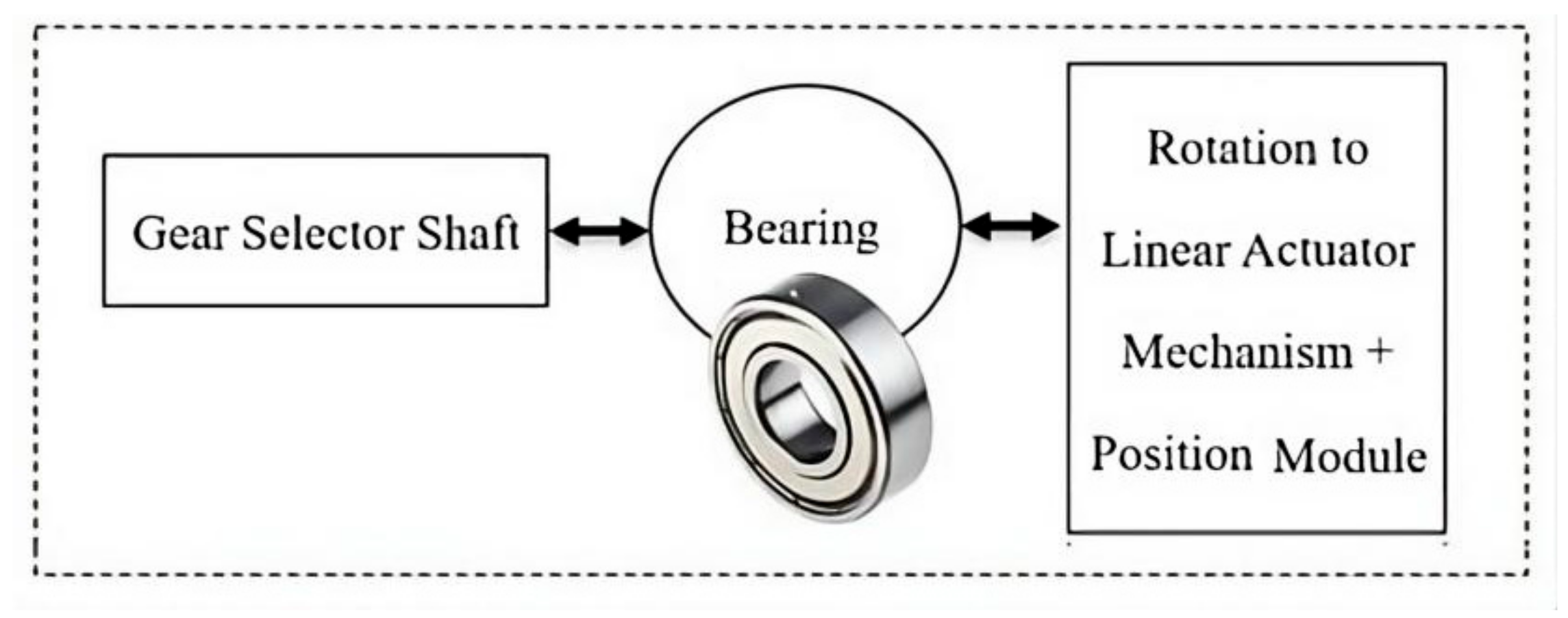
The block diagram of the mechanical gear shifter shows that the gear selector can rotate and, thus, drive the shaft to move along the X-axis by using the linear actuator mechanism and position module via the bearing module, as shown in Figure 3. It consists of a bearing link with a bearing of the specification (ID 8 × OD 14 × W 4) that prevents the rotational torque from acting on the structure. The compatible mechanism is designed with the following: 1. N20 powered actuation unit. 2. Bearing interlink. 3. Rotational linear motion converter. 4. Accurate position-finding module. More details are demonstrated as follows.
(a)
Main rack gear support structure
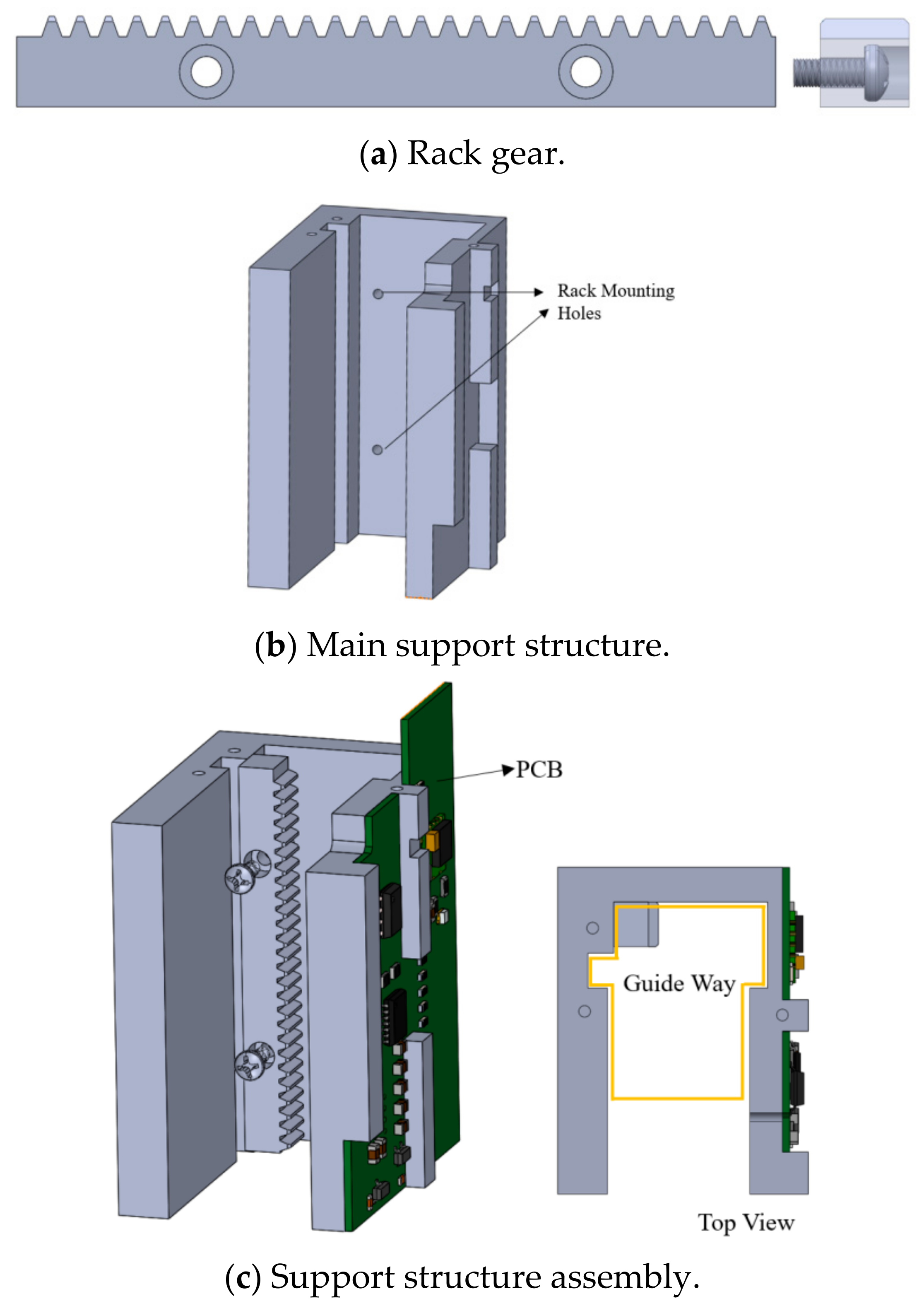
A rack gear mechanism with a 0.5 module of an industry standard unit is used to achieve linear motion, as shown in Figure 4a. An M1.6 × 4 screw is used to mount the rack to the support structure. The main support structure is shown in Figure 4b, containing the mounting screw holes and a guide way compatible for the linear mechanism. The outer dimension of the support structure is 36.50 × 28 × 43 (mm). The whole assembly, with the PCB and the rack combined, is shown in Figure 4c.
(b)
Movable guide
The design of the movable guide mechanism is shown in Figure 5. It uses the rotational motion of the N20 motor, i.e., a DC mini metal gear motor, and the rack gear to move linearly within the guide way (X-axis) in a fixed direction. The shifting force uses the N20 motor for shaft movement. The major specifications include the following: Revolving Speed: 100 RPM @ 6 V • Load Speed: 80 RPM • Rated Torque: 2 kg.cm • Stall Torque: 16 kg.cm • Rated Current: 0.07 A • Stall Current: 1 A • Reduction Ratio: 1:10. It consists of slots for the N20 motor with the bearing and the position pin. The friction of the motor used to control the movement of the pinion gear is locked into the motor slot using tight tolerance. A pinion gear combined with a gear selector shaft is mounted on the rack gear to move the shaft. Therefore, the perfect mesh of components to achieve directional linear actuation and motion is shown. Also, the rotational torque is neutralized using a bearing link. The gear specification is listed in Table 1.
Overall, the design of the gear shifter is based on the principles of simplicity and a standard mechanism that is easy to produce. There are no special configurations or tools required in the CNC machining process. Besides, the deformable parts like the rack and the gear sets are isolated from the main structure, and materials like steel are used to decrease the overall weight, making the replacement of parts easy. The remaining parts are made using aluminum or plastic, as shown in Table 2.

3. Design of Shifter Controller

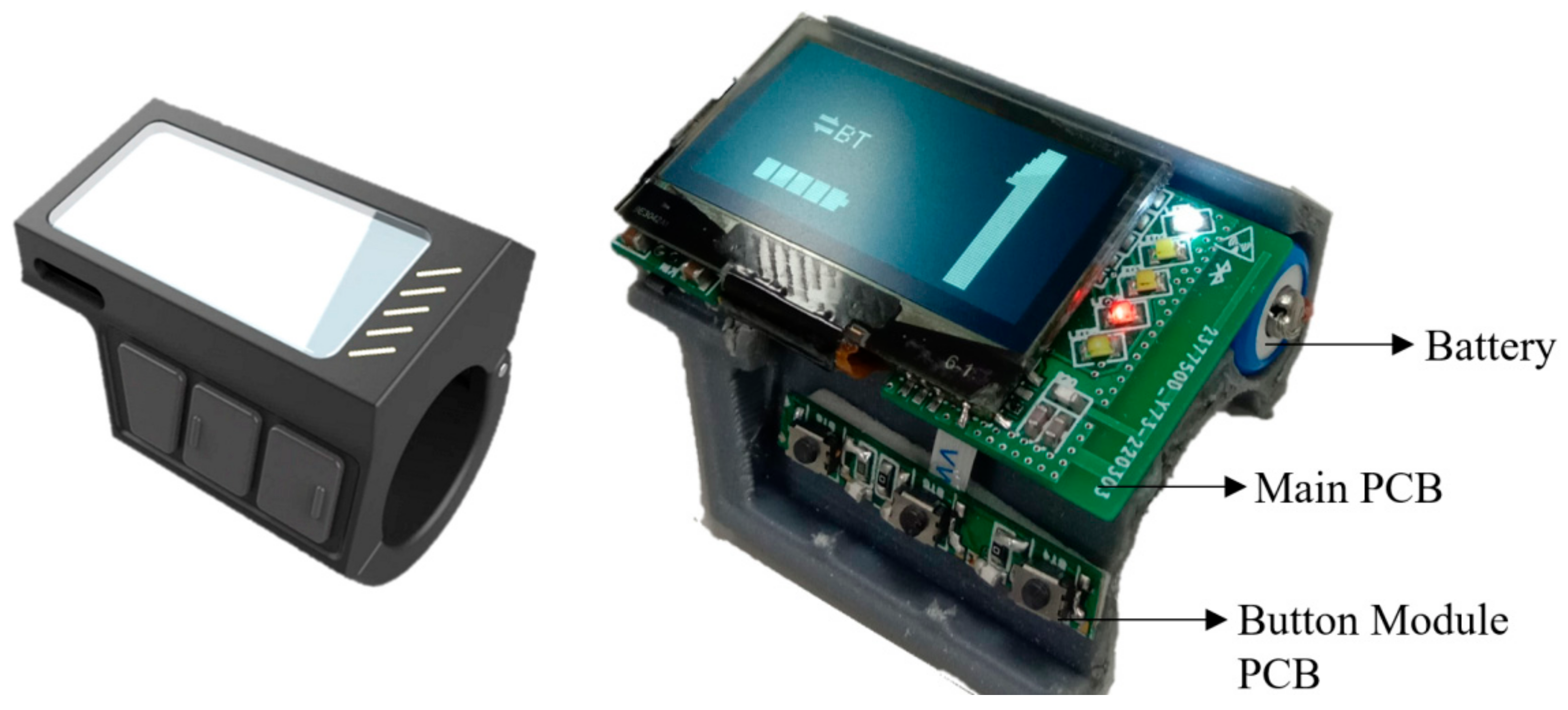
The designed controller module considers rider ergonomics based on finger operation with LCD monitoring, as shown in Figure 6. The user can comfortably shift gears using the input buttons placed in the most comfortable shifting angle and position using their thumb or finger. An OLED display angled to be in the user’s eyeline is also designed to display the gear and battery status, including LEDs for gear status, low battery warning, and shift blinks.

3.1. System Hardware Architecture

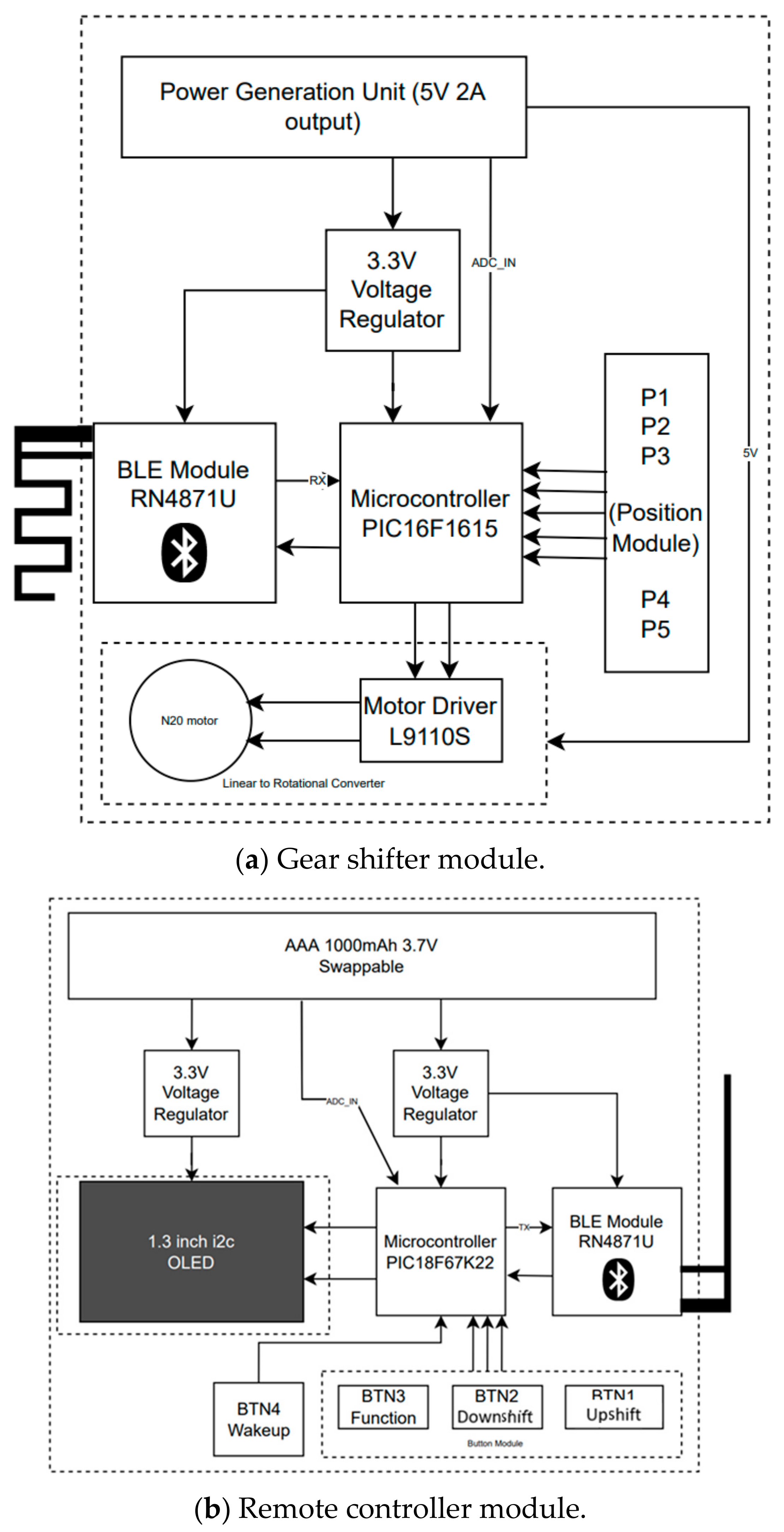
The system’s hardware architecture contains two sub-systems: 1. A gear shifter module, as shown in Figure 7a. 2. A remote control module, as shown in Figure 7b. The sub-modules are bridged together via UART communication, where BLE (RN4871U, Microchip Technology, Chandler, AZ, USA) is used on both ends with different types of onboard antenna, i.e., MIFA (Meandered Inverted F Antenna) on the shifter and an inverted F-Type antenna on the controller [18]. The remote controller module uses an 8-bit PIC18F67K22 (Microchip Technology, USA), and the gear module is controlled using an 8-bit PIC16F1615 (Microchip Technology, USA) microcontroller combined with an N20 motor. The position module is designed using a contact pad, where a movable contact pin is used to shorten the points, thus allowing appropriate positions to be detected.

3.2. Design of Gear Shifter Circuit

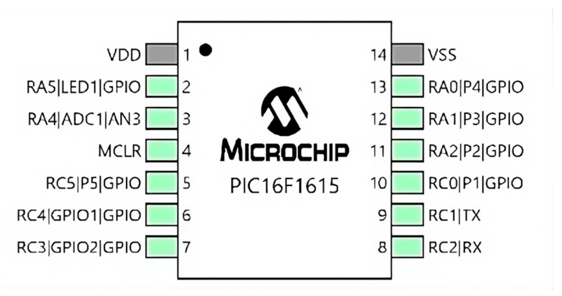
The MCU (PIC16F1615) is used for gear shifter control, as shown in Figure 8. It is configured with GPIOs for a contact pad-based position acquisition system (P1, P2, P3, P4, P5), an analog-to-digital converter (ADC) is used to measure the battery voltage and administer low power warnings, UART (RX, TX) is used for data transmission and reception via BLE, and one status light (LED) is configured to notify users of low power and Bluetooth status. The circuit design specification is shown in Table 3.
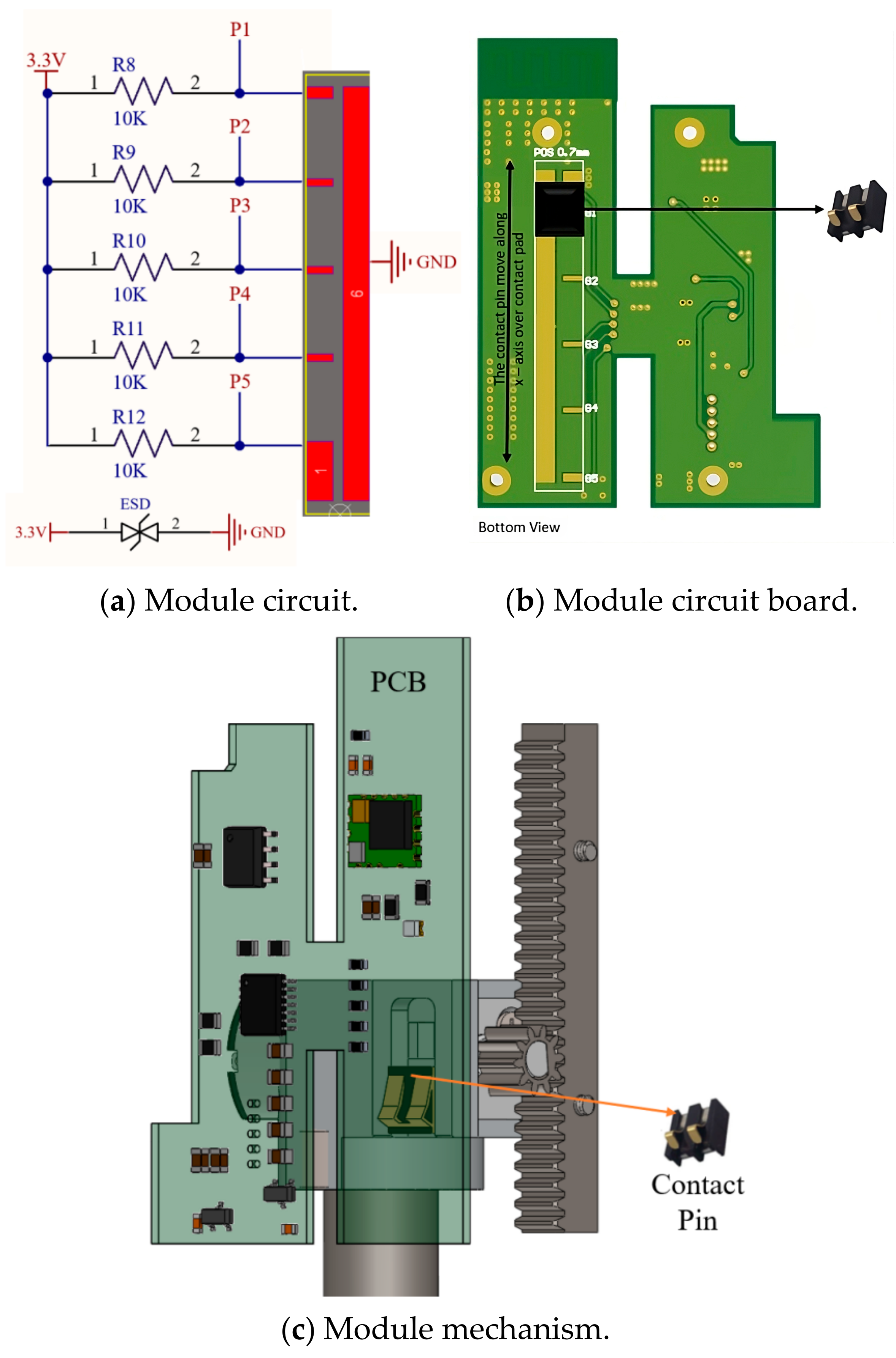
The position of the module circuit with the gear mechanism is shown in Figure 9. This simple array involves a switching circuit with a pitch distance of 7 mm. The contact points (P1, P2, P3, P4, P5) in Figure 9a are connected to individual input GPIO pins. A spring pin is mounted on the slot in the movable guide so that it can touch the appropriate points with the short circuit when moving against it, as shown in Figure 9b. The contact points are perfectly aligned to the gears’ engaged positions and the path of linear motion, as shown in Figure 9c.

3.3. Design of Remote Controller Circuit

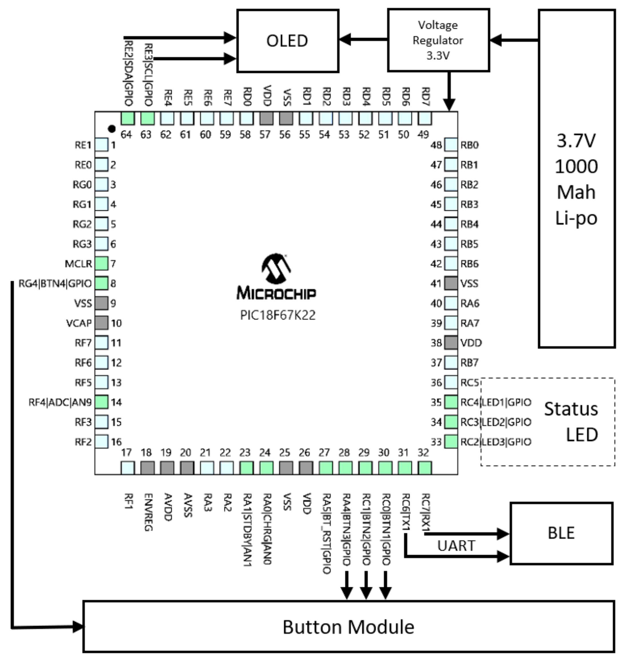
The pin configuration of the remote controller based on MCU is shown in Figure 10, where UART (RX, TX) is used for communication, I2C for display operation (SDA, SCL), and multiple LEDS (LED1, LED2, LED3) signify low power, connectivity, and shift blink, respectively. The specification of the remote controller is listed in Table 4.
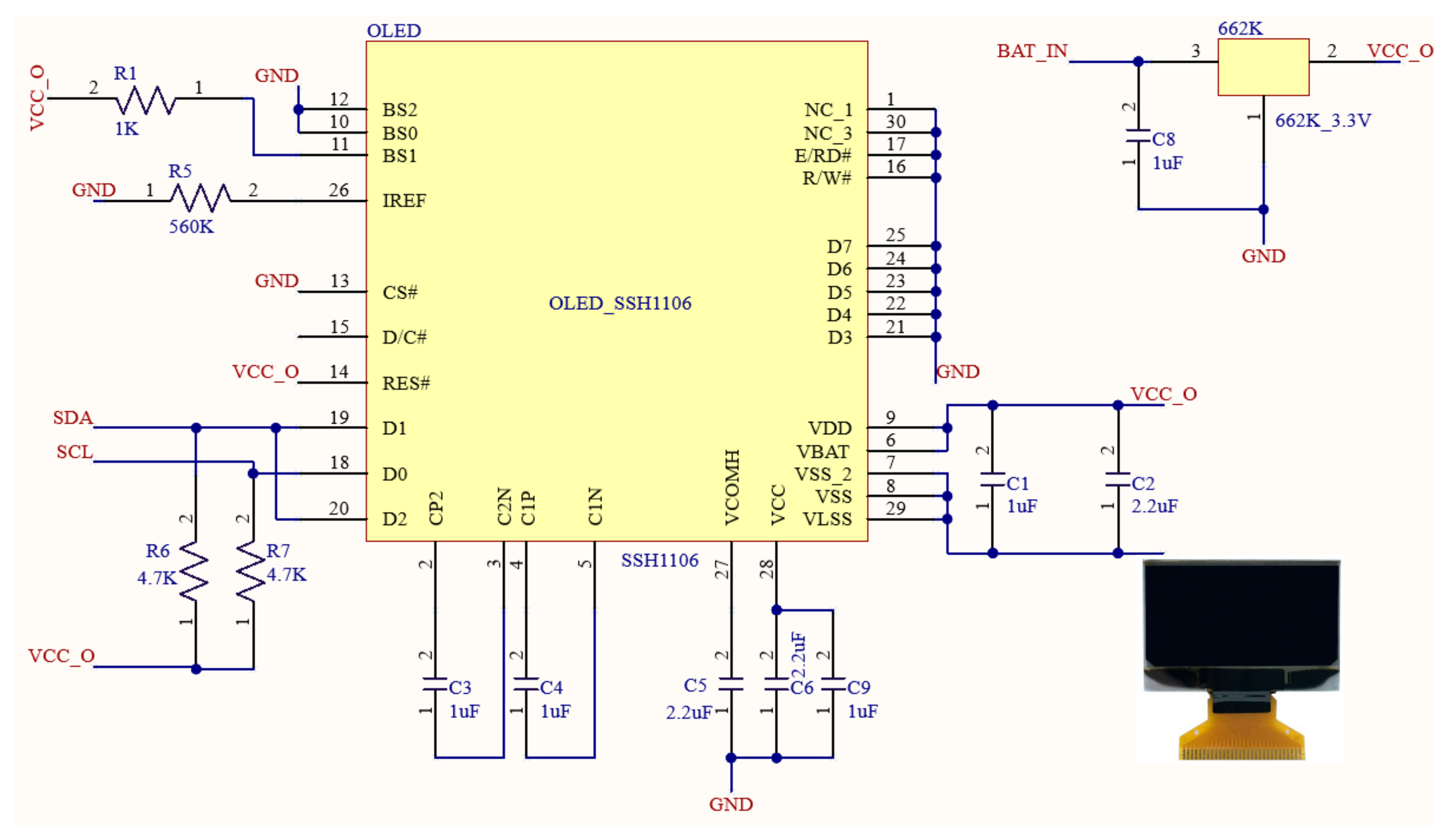
The circuit diagram for the OLED module using a 1.3 inch display is shown in Figure 11. Here, it is integrated to the main PCB, and an onboard connector is used to directly weld the component to the PCB.

4. Design of System Software

MPLAB software (MPLAB X IDE v6.20) is used to compile and debug using the PICKIT3 IC Debugger (Microchip Technology, USA) hardware and XC8 Compiler (Microchip Technology, USA). The overall system is divided into two subsystems: 1. Remote controller module. 2. Gear shifter module. The software algorithm for the overall system operation is as follows:
(1).
Remote side:
(a)
Get the input from the user.
(b)
Store the response in a variable.
(c)
Transmit the shift data.
(d)
Update the gear status in the OLED display.
(2).
Shifter side:
(a)
Receive the input.
(b)
Gear: process the input.
(c)
Get the current position from the position module.
(d)
Shift to the appropriate gear and end the process.

4.1. Architecture of Remote Controller Software

The complete software architecture of the remote control module is shown in Figure 12 and described below.
(1).
Initialize the MCU, OLED, and BLE modules.
(2).
Search for BLE connection. Update the interface, including OLED and status LED.
(3).
Initialize to Gear 1 and wait for user input.
(4).
If the user upshifts, process the data and send appropriate data to the wireless transmission system, and update the user interface and store it to a variable.
(5).
If the user downshifts, process the data and send appropriate data to wireless transmission system, and update the user interface and store it to a variable.
(6).
Check the battery status and update the OLED information according to mapped ADC values.
(7).
If the wake up button is long pressed, perform an alternate operation of either wake up or sleep.
(8).
If the connection is terminated, update the OLED, turn off the status LED, and search for the connection again.

4.2. Architecture of Gear Shifter Software

The complete architecture of the gear shifter is shown in Figure 13 and described below.
(1).
Initialize the MCU and initialize Gear 1.
(2).
Search for a BLE connection and update the LED status.
(3).
Receive data from the BLE and store it in a variable.
(4).
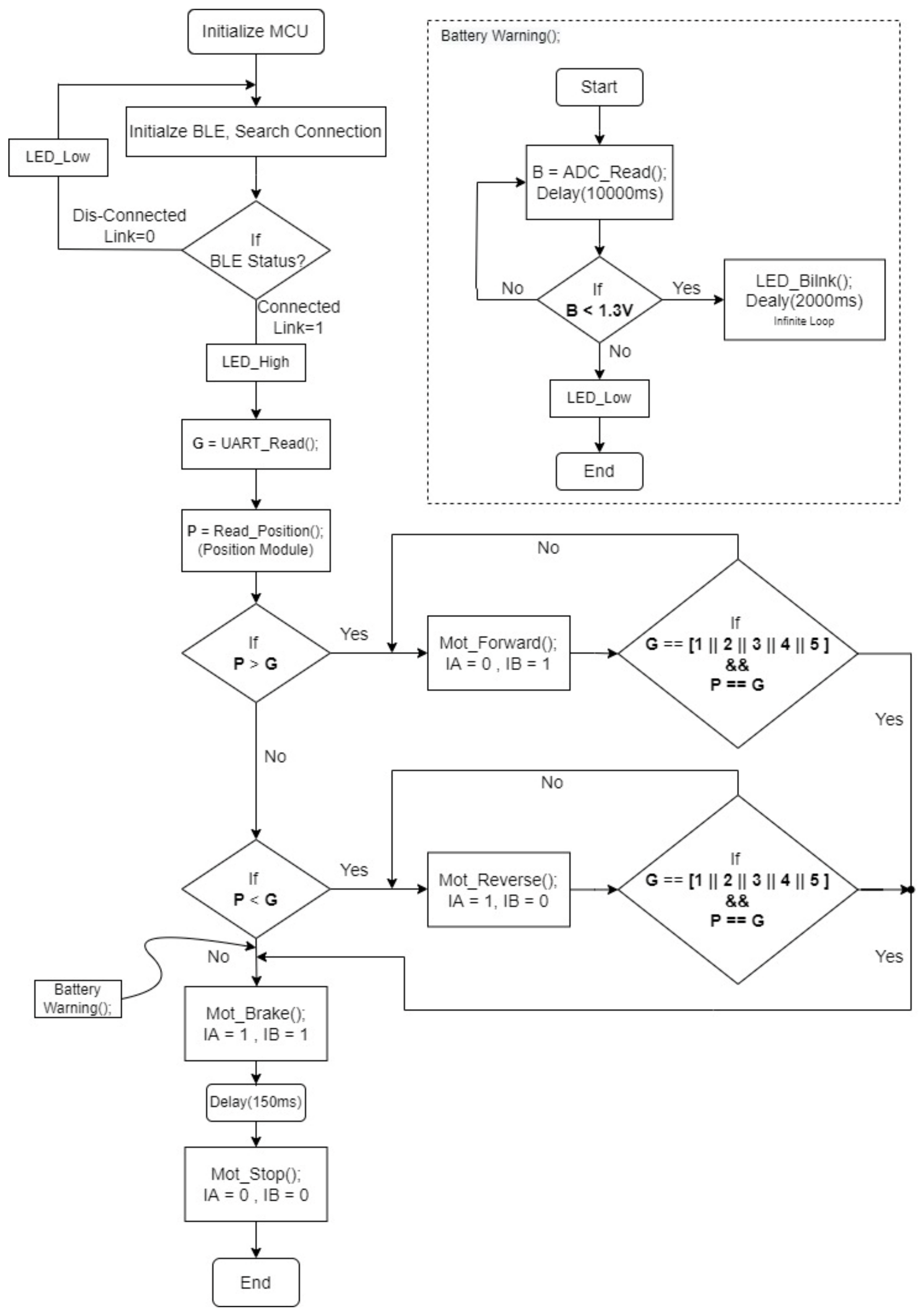
Find the current gear position, as shown in Figure 14.
(5).
Process the data and perform motor actions based on the processed data.
(6).
If the received data and the current status are equal, stop the motor.
(7).
Check the battery status, blink the LED if the battery is low.
(8).
If the connection is terminated, turn off the status LED and search for the connection again.

5. Experimental Results and Analysis

5.1. Gear Shifter Module and Remote Controller Module

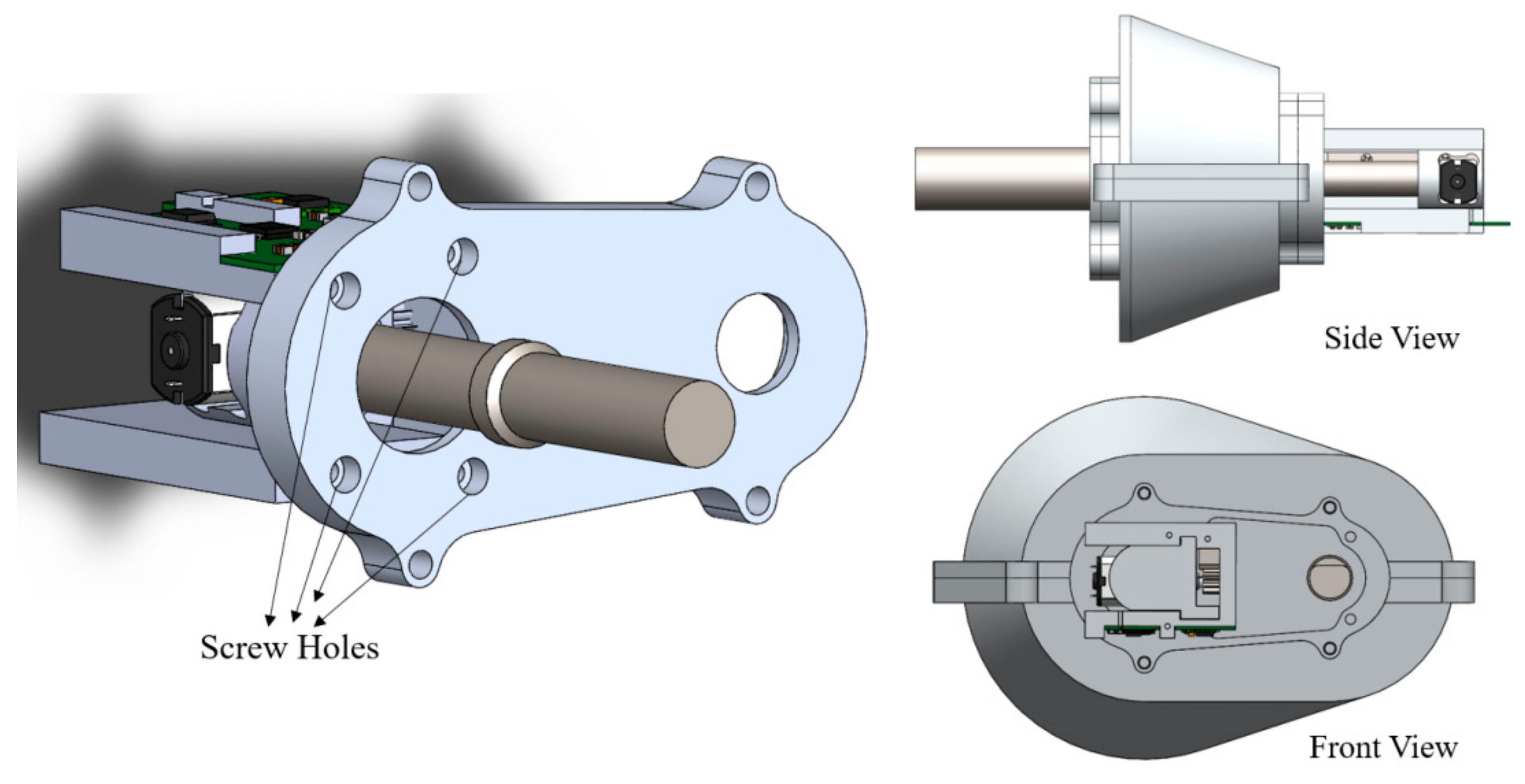
A complete assembly of all the mechanical and electronic components are used in the experimental testing. The designed gear shifting module is affixed to the gear box using the screw holes from under the structure, as shown in Figure 15. The movable guide can be aligned to any position along the guide way. Once the system is turned on, the system will automatically shift to the first gear. This avoids assembling time and complexity, and no special calibration or tools are required during assembly.
The remote controller module assembly is shown in Figure 16, where a sectional casing is used to display the internal components and to show the internal assembly.

5.2. Real-Time Gear Shift Testing

A test is set up using the assembly of the gear box, drive train, and gear shifter module. It is mounted to two different riding platforms: 1. Normal posture. 2. Recumbent posture. Sequential up- and downshifts are tested for sequential shifting operations on roads, as shown in Figure 17.
The gear engaging operation from Gear 1 to Gear 5 is shown in Figure 18. Note that each gear position of an actuator marked a yellow arrow is in respect to a downshift or initialization position.

5.3. Results and Analysis

System functions including the wake up process, battery indicator, Bluetooth connection, and status indicator were tested during real-time implementation. A trainer stand setup and full speed hand cranking were used to test the gear shift. The output functions like OLED graphics and actuator movement from each shift input are tabulated in Table 5. Based on the shift sequence with respect to gear position, it is unveiled that the system works smoothly as programmed, without any issues. The results also illustrate that the motor cannot move further once it reaches one of the ends. The end positions are marked and programmed to stop the motor if input > 5 and input < 1. The user interface is achieved in real time and the graphics functions are mapped accurately with respect to the programmed values. Similarly to existing e-shifters in the market, the shifting time takes around 0.35 s, sufficiently reacting to instructions received, automatic pairing, and gear shifting.
In conclusion, it is obvious that the electronic-controlled shaft control system is easy to operate and handle. More importantly, it can provide more reliability and robustness and better serviceability without some of the drawbacks of traditional chain-driving mechanics, such as dirt and loosening problems. Moreover, the proposed control system presents a lower cost than the currently available products due to the lack of requirement for additional sensors and complex hardware circuits in the system.

6. Conclusions

The operation of a wireless-controlled shaft driving train has been achieved successfully in this study. It has been verified that the proposed system can automatically pair with and wirelessly receive commands from the remote controller, and it can accurately perform gear shifting operations using its position module. All real-time shifting information can be shown on the OLED display. These functions surely fix the limitations of traditional drive trains so that the usage of high-maintenance cables, derailleurs, and chains can be completely eliminated. For example, an actuated gear shifter module is perfectly coordinated with the gear positioning system. In addition, the remote controller module combined with the OLED display and shift operation buttons make the shifting easier and also meet modern demands. The experimental results confirm that the designed system is reliable, fast, and requires less maintenance, advancing technological progress in the bicycle industry.

Author Contributions

Methodology, H.-C.L.; Software, E.C.; Formal analysis, E.C.; Data curation, E.C.; Writing—original draft, H.-C.L.; Writing—review & editing, H.-C.L.; Supervision, H.-C.L.; Funding acquisition, H.-C.L. All authors have read and agreed to the published version of the manuscript.

Funding

This research received no external funding.

Data Availability Statement

The original contributions presented in this study are included in the article. Further inquiries can be directed to the corresponding author.

Conflicts of Interest

The authors declare no conflict of interest.

References

  1. Lin, H.C.; Chen, J.W.; Wang, M.D. Development of bike self-damping adjustment system using proportional accumulation control algorithm. J. Chin. Inst. Eng. 2024, 47, 997–1010. [Google Scholar] [CrossRef]
  2. Palwe, S. Bicycle Market Research Report. ID: MRFR/AM/5463-CR 2020. pp. 1–188. Available online: https://www.marketresearchfuture.com/reports/bicycle-market-6928 (accessed on 1 October 2020).
  3. Rackov, M.; Kuzmanović, S.; Knežević, I.; Čavić, M.; Penčić, M.; Čavić, D.; Cofaru, N.F. Analysis of Possible Concept Solutions of Chain Drives. In Proceedings of the 9th International Conference on Manufacturing Science and Education–MSE 2019 Trends in New Industrial Revolution, Sibiu, Romania, 5–7 June 2019; Volume 290. [Google Scholar] [CrossRef]
  4. Gaikwad, V.S.; Jadhav, A.B.; Kadam, A.K.; Joshi, V.U. A Review on Design and Performance analysis of Shaft Driven Bicycle. Int. J. Adv. Eng. Manag. (IJAEM) 2020, 2, 1112–1114. [Google Scholar]
  5. Gangadhar, K.; Sydanna, T.R.; NagaKiran, M.; Salmon, A. Design and analysis of shaft driven bicycle. Int. J. Res. 2017, 4, 1951–1954. [Google Scholar]
  6. Awari, M.; Mishra, H. Design of driven assembly of shaft driven bicycle. Int. J. Adv. Res. Innov. Ideas Educ. 2018, 4, 476–484. [Google Scholar]
  7. Baldissera, P.; Delprete, C.; Zahar, A. Design and Construction of a Moving Cassette Electronic Gear-Shift for Human Powered Vehicles. Machines 2019, 7, 55. [Google Scholar] [CrossRef]
  8. Rockwood, D.; Parks, N.; Garmire, D. A continuously variable transmission for efficient urban transportation. Sustain. Mater. Technol. 2014, 1–2, 36–41. [Google Scholar] [CrossRef]
  9. Bilawane, R.R.; Agroya, S.; Rewatkar, S.; Teltumbde, S.; Kanholkar, S.; Mohod, S.; Patil, U.; Kanfade, S. Design and Fabrication of Chainless Bicycle. Int. Res. J. Educ. Technol. 2022, 4, 114–117. [Google Scholar]
  10. Marques, R.; Hernández-Herrador, V.; Calvo-Salazar, M. Sevilla. A successful experience of bicycle promotion in a Mediterranean context. WIT Trans. Ecol. Environ. 2014, 191, 769–781. [Google Scholar] [CrossRef]
  11. Saponara, S.; Moras, R.; Roncella, R.; Saletti, R.; Benedetti, D. Performance measurements of energy storage systems and control strategies in realworld e-bikes. In Proceedings of the 2016 IEEE Sensors Applications Symposium (SAS), Catania, Italy, 20–22 April 2016; pp. 1–6. [Google Scholar] [CrossRef]
  12. Dozza, M.; Fernandez, A. Understanding Bicycle Dynamics and Cyclist Behavior from Naturalistic Field Data (November 2012). IEEE Trans. Intell. Transp. Syst. 2014, 15, 376–384. [Google Scholar] [CrossRef]
  13. Thakkar, D.; Dhonde, S.; Dhorage, P.; Kshirasagar, D. Automation of Gears in Bicycle. Int. J. Res. Appl. Sci. Eng. Technol. 2022, 10, 60–61. [Google Scholar] [CrossRef]
  14. Tsai, C.C.; Kao, J.C.; Chang, C.F. Interval type-2 fuzzy gear-changing control for intelligent bikes. In Proceedings of the 2014 International Conference on Machine Learning and Cybernetics, Lanzhou, China, 13–16 July 2014; pp. 741–747. [Google Scholar] [CrossRef]
  15. Lin, T.Y. Apply fuzzy logic to smart-bike controller design. In Proceedings of the Fourth International Symposium on Uncertainty Modeling and Analysis. 2003 ISUMA 2003, College Park, MD, USA, 21–24 September 2003; pp. 208–212. [Google Scholar] [CrossRef]
  16. Dutta, P.; Dontiboyina, U. NaviRide: Smart Bicycle Computer with GPS Waypoint Indicators. In Proceedings of the 2016 Second International Conference on Computational Intelligence & Communication Technology (CICT), Ghaziabad, India, 12–13 February 2016; pp. 472–477. [Google Scholar] [CrossRef]
  17. Faroqi, A.; Nuraeni, E.; Belawi, H.; Ulfiah. Design of Heart Rate Equipment Base On Bluetooth Communication On Bike Speedometers. In Proceedings of the 2020 6th International Conference on Wireless and Telematics, Yogyakarta, Indonesia, 3–4 September 2020; pp. 1–4. [Google Scholar] [CrossRef]
  18. Koodtalang, W.; Sangsuwan, T. Improving motorcycle anti-theft system with the use of Bluetooth Low Energy 4.0. In Proceedings of the 2016 International Symposium on Intelligent Signal Processing and Communication Systems (ISPACS), Phuket, Thailand, 24–27 October 2016; pp. 1–5. [Google Scholar] [CrossRef]
  19. Savaresi, D.; Dett`u, F.; Formentin, S.; Savaresi, S. ComfortOriented Gear Shifting in City Bicycles. In Proceedings of the 2020 IEEE Conference on Control Technology and Applications (CCTA), Montreal, QC, Canada, 24–26 August 2020; pp. 436–441. [Google Scholar] [CrossRef]
  20. Lin, H.C.; Chelliah, E. Design of Wireless Gear Shifter for Shaft Driven Bicycle. In Proceedings of the 16th Intelligent Living Technology Conference, Taichung, Taiwan, 2 June 2022. [Google Scholar]
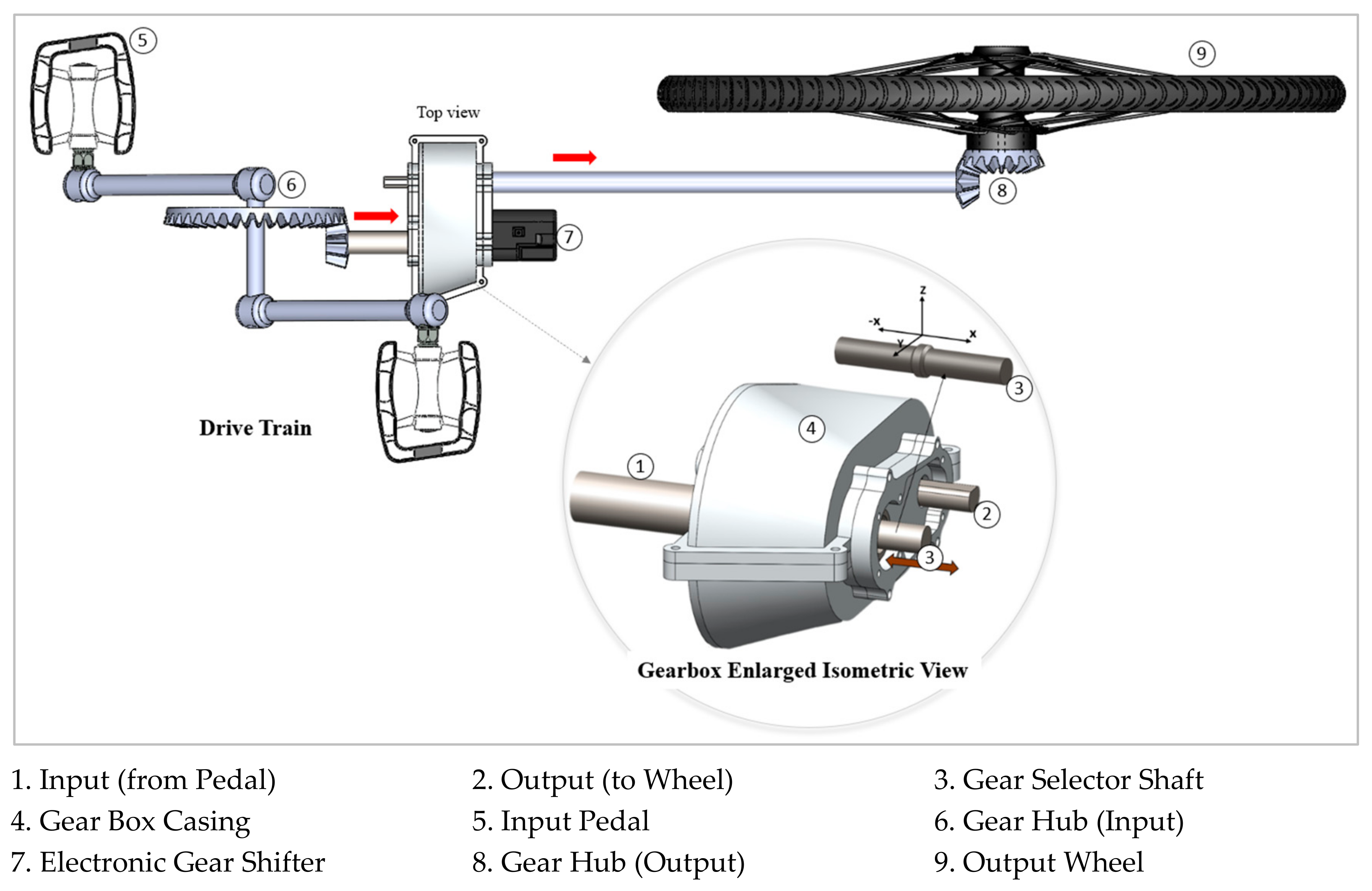
Figure 1. Profile of driving train assembly.
Machines 13 00003 g001
Figure 2. Schematic diagram of gear engagement mechanism.
Machines 13 00003 g002
Figure 3. Mechanical gear shifter approach.
Machines 13 00003 g003
Figure 4. Support structure of main rack gear.
Machines 13 00003 g004
Figure 5. Mechanic diagram of movable guide (internal view: left, top view: right).
Machines 13 00003 g005
Figure 6. Diagram of controller module.
Machines 13 00003 g006
Figure 7. Architecture of controller modules.
Machines 13 00003 g007
Figure 8. MCU configuration of gear shifter.
Machines 13 00003 g008
Figure 9. Position module diagram.
Machines 13 00003 g009
Figure 10. Pin configuration of remote controller.
Machines 13 00003 g010
Figure 11. OLED circuit.
Machines 13 00003 g011
Figure 12. Flowchart of remote controller software.
Machines 13 00003 g012
Figure 13. Flowchart of gear shifter software.
Machines 13 00003 g013
Figure 14. Flowchart of gear status software.
Machines 13 00003 g014
Figure 15. Gear shifter assembly.
Machines 13 00003 g015
Figure 16. Remote controller module assembly.
Machines 13 00003 g016
Figure 17. Real-time riding test.
Machines 13 00003 g017
Figure 18. Gear engaging operation.
Machines 13 00003 g018
Table 1. Gear specification.
ComponentSpecification
Pinion gear
Machines 13 00003 i001
Module: 0.5
Teeth: 10
Diameter: 6
Width: 5
Bore Diameter: 3 mm
Rack gear
Machines 13 00003 i002
Module: 0.5
Rack Length: 42 mm
Height: 5 mm
Width: 5 mm
Table 2. Materials of mechanical parts.
PartMaterial
Pinion gearSteel
Rack gearSteel
ScrewsStainless steel
Main support structureAluminum
Movable guideAluminum
Remote controller casingPlastic
Remote controller buttonsSilicon rubber
Table 3. Module circuit specification.
Input Voltage5 V
Operating voltage (MCU)3.3 V
Operating voltage (BLE)3.3 V
Operating voltage (motor driver)5 V
N20 Motor Torque/RPM1.5 KG (5 V)/100
Communication BLE (UART)
Number of gear position/Pitch 5/7 mm
Table 4. Remote controller specification.
ItemSpecification
Operating voltage3.3–3.7 V (AAA 1000 maH battery)
Display1.3 inch i2c OLED
Button
(1).
BTN1—Upshift
(2).
BTN2—Downshift
(3).
BTN3—Function
(4).
Power button
User interface
(1).
Display
(2).
Current gear
(3).
Power
(4).
Welcome logo
(5).
LED
(6).
Low power notification
(7).
Bluetooth status
(8).
Shift blinks
Table 5. System output mapping.
Sequence (Input)Real-Time Gear Position (Output: Motor Turn)Position (Sensing Unit)OLED (Output)
System ResetMachines 13 00003 i003If (P1) == get value
Motor (stop)
Machines 13 00003 i004
UpMachines 13 00003 i005If (P2) == get value
Motor (stop)
Machines 13 00003 i006
UpMachines 13 00003 i007If (P3) == get value
Motor (stop)
Machines 13 00003 i008
UpMachines 13 00003 i009If (P4) == get value
Motor (stop)
Machines 13 00003 i010
UpMachines 13 00003 i011If (P5) == get value
Motor (stop)
Machines 13 00003 i012
UpMachines 13 00003 i013Cannot move further
Motor (stop)
Machines 13 00003 i014
DownMachines 13 00003 i015If (P4) == get value
Motor (stop)
Machines 13 00003 i016
DownMachines 13 00003 i017If (P3) == get value
Motor (stop)
Machines 13 00003 i018
DownMachines 13 00003 i019If (P2) == get value
Machines 13 00003 i020
DownMachines 13 00003 i021If (P1) == get valueMachines 13 00003 i022
DownMachines 13 00003 i023Cannot move further
Motor (stop)
Machines 13 00003 i024
Disclaimer/Publisher’s Note: The statements, opinions and data contained in all publications are solely those of the individual author(s) and contributor(s) and not of MDPI and/or the editor(s). MDPI and/or the editor(s) disclaim responsibility for any injury to people or property resulting from any ideas, methods, instructions or products referred to in the content.