Article

Adaptive Neuro-Fuzzy Inference System-Based Predictive Modeling of Mechanical Properties in Additive Manufacturing

by
Vasileios D. Sagias
1,
Paraskevi Zacharia
2,*,
Athanasios Tempeloudis
1 and
Constantinos Stergiou
1
1
Department of Mechanical Engineering, University of West Attica, 12241 Egaleo, Greece
2
Department of Industrial Design and Production Engineering, University of West Attica, 12241 Egaleo, Greece
*
Author to whom correspondence should be addressed.
Machines 2024, 12(8), 523; https://doi.org/10.3390/machines12080523
Submission received: 29 June 2024 / Revised: 25 July 2024 / Accepted: 29 July 2024 / Published: 31 July 2024
(This article belongs to the Section Advanced Manufacturing)

Abstract

:
Predicting the mechanical properties of Additive Manufacturing (AM) parts is a complex task due to the intricate nature of the manufacturing processes. This study presents a novel application of the Adaptive Neuro-Fuzzy Inference System (ANFIS) to predict the mechanical properties of PLA specimens produced using Fused Filament Fabrication (FFF). The ANFIS model integrates the strengths of neural networks and fuzzy logic to establish a mapping between the inputs and the output mechanical properties, specifically maximum stress, strain, and Young’s modulus. Experimental data were collected from three-point bending tests conducted on FFF samples fabricated from PLA material with different manufacturing parameters, such as infill pattern, infill, layer thickness, printing speed, extruder and bed temperature, printing orientation (along each axis and twist angle), and raster angle. These data were used to train, check, and validate the ANFIS model. The results reveal that the proposed predictive model can effectively predict the mechanical properties of FFF-printed PLA samples, demonstrating its potential for broader applications across various AM technologies and materials, ultimately enhancing the efficiency and effectiveness of the AM fabrication process.

1. Introduction

Within the context of the fourth industrial revolution, several science sections merge with each other in order to lead industry to new horizons. Fuzzy modeling, a tool which can impressively represent nonlinear relations between the parameters of a system [1], along with adaptive Artificial Neural Network (ANN) results in the Adaptive Neuro-Fuzzy Inference System (ANFIS). ANFIS can establish input–output systems based on both “if–then” rules and specified input–output data pairs [2]. This combination takes advantage of both tools in a single framework.
Additive Manufacturing is a rapidly expanding technology, applied to a wide range of industrial sectors, transforming design files to functional products as well as parts and assemblies. The main advantages of AM are the freedom of design, sustainability in energy and materials, the ability for complex structures to be manufactured, and the affordability in fast prototyping. However, AM still faces low productivity and uncertainty of the parts, regarding their mechanical properties. The main reason is the multifactorial process parameters that influence the manufacturing procedure.
Several studies have been made to propose new methods and materials in AM, offering solutions and further development on the AM, as it is one of the four manufacturing pillars. In 1986, Charles Hull presented a new technology in which successive layers of materials are formed on top of each other creating three-dimensional parts. This new process was named stereolithography (SLA). Since then, new methods are being developed, and novel materials are being applied, allowing new applications and industry fields to continuously merge with AM.
ASTM classifies Additive Manufacturing into seven major categories [3]: Material Extrusion, Powder Bed Fusion, Sheet Lamination, Binder Jetting, Material Jetting, VAT Photopolymerization, and Direct Energy Deposition. Among these, Material Extrusion is the most widely used AM process. In this method, the material is selectively dispensed through a heated nozzle following a layer-by-layer path to create a physical model.
The large variety of materials, used in AM, can be categorized [4] into four groups: Metals and Alloys, Polymers and Composites, Ceramics, and finally Concrete, most of which can be used in Material Extrusion processes.
New Additive Manufacturing (AM) technologies are continually being developed, and the variety of materials utilized in these processes is expanding rapidly. Moreover, AM, also known as 3D printing, is experiencing rapidly growth due to its facilitation capabilities, having a key role in industries, such as aerospace, oil and gas, automotive, energy, medical, tool and die, and other consumer goods [5]. As Artificial Intelligence (AI) tools can be applied to control the factors that affect the mechanical properties of the materials [6,7], this study will explore the convergence of AM and ANFIS. The aim is to develop a tool that can predict the mechanical properties of specimens, taking into consideration most of the manufacturing parameters of AM processes, thereby enhancing the efficiency of AM applications.
Although Additive Manufacturing is gaining popularity, due to its reduced product cycle time and the lack of need for expensive tools, the commercialization of this technology is still limited because of several shortcomings. One significant issue is the difficulty in determining the strength of the parts, which arises from the anisotropic and heterogeneous microstructure of the fabricated parts. The most critical material characteristics are the mechanical properties, as they determine the product’s ability to meet the designed requirements. These properties, which include stress, strain, and Young’s modulus, depend on various parameters, such as the applied AM method, material, infill pattern and percentage, layer thickness, the existence of wall and its thickness, temperature, building orientation, curing conditions, and many more.
Previous studies [8,9,10,11,12,13,14,15,16,17,18,19,20] in the field have usually focused on a limited number of the most significant parameters, within the strict boundaries of the conducted experiments, using several experimental, numerical, and statistic methods.
This research is triggered by the need to develop a unified tool for predicting the mechanical properties of AM parts, adaptable to AM technology and material, while accounting for the various process parameters that impact the final product. The mechanical properties to be approached are maximum stress, strain, and Young’s modulus.
With the rapid evolution of AM technologies and the range expansion of used materials, the application of AM structures is continuously widening. Therefore, Artificial Intelligence (AI) can be employed to control the factors that affect the mechanical properties of the materials [4].
This study examines the synergy between Additive Manufacturing (AM) and Artificial Intelligence (AI) to develop an AI tool aimed at enhancing the understanding and efficient use of materials in AM. This tool will be used to predict the mechanical properties of the specimens, considering the majority of setting parameters during the AM process, thereby benefiting research and practical applications.

2. The Adaptive Neuro-Fuzzy Inference System (ANFIS)

The modeling of processes and system identification using input–output data has attracted many research efforts. The main components of soft computing, such as fuzzy logic and neural networks, have shown great ability in solving complex nonlinear system identification and control problems. The Adaptive Neuro-Fuzzy Inference System (ANFIS) model [2] is a hybrid predictive model that combines the learning capabilities of Artificial Neural Networks (ANNs) with the reasoning capabilities of fuzzy logic. ANFIS uses input–output sets and a series of if–then fuzzy rules to incorporate the human-like reasoning style of fuzzy inference systems (FISs). The ANFIS model is especially effective in a variety of engineering applications [21,22,23,24,25,26], when data are inconsistent or nonlinear, where conventional methods fail or are too complicated to employ.
A typical ANFIS structure consists of five layers, wherein each layer is constructed by several nodes. The outputs of the previous layer are used as input nodes for the current layer. Considering a first-order Sugeno fuzzy model with two inputs x and y and one output f, a typical rule set with two fuzzy if–then rules can be expressed as follows:
  • Rule 1: if (x is A1) and (y is B1), then (f1 = p1x + q1y + r1).
  • Rule 2: if (x is A2) and (y is B2), then (f2 = p2x + q2y + r2).
Where x, y are inputs, Ai, Bi are membership functions and pi, qi, ri are consequent parameters, and i is the node number. The corresponding equivalent ANFIS architecture is shown in Figure 1. The entire system architecture consists of five layers, namely, the fuzzy layer (Layer 1), product layer (Layer 2), normalized layer (Layer 3), consequence layer (Layer 4), and total output layer (Layer 5). The number of nodes in other layers (layer 2–4) relates to the number of fuzzy rules (R).
The basic idea behind using neuro-adaptive learning techniques is that it is very simple and allows implementation of multi-input–single-output first-order Sugeno-type FIS. This technique provides a method for the fuzzy modeling procedure to learn information about a dataset, in order to compute the membership function parameters that best allow the associated fuzzy inference system to track the given input/output data. This learning approach takes place prior to the operation of the control system. The ANFIS methodology can be decomposed into four steps:
Step 1: A set of input–output data, to be used as training data, is obtained from the sewing process. Another optional dataset can be used as test data after training.
Step 2: The initial Sugeno-type FIS structure, regarding antecedent membership functions, number of rules, and consequence parameters, is created.
Step 3: The learning process is carried out using the training data to adjust the membership functions, to create the interference rules, and to determine the consequent parameters.
Step 4: The model is validated using the testing data, which have not been used during the training. The objective of this validation is to validate its generalization capability.

3. Experimental Results and Validation

Through a literature review and experiments [9], many factors that influence the mechanical properties of the AM specimens were gathered. By the use of Taguchi methodology and sensitivity analysis, these factors were classified according to their impact on the mechanical properties of the specimens. These factors and their values were selected as an input to the ANFIS model. Bending, tension, and torsion experiments were conducted on various materials with the use of many AM technologies, such as SLA, FFF, SLS, etc. All experiments were conducted according to ASTM standards such as ASTM D638, D695, D7791, D790, and D5279 [27,28,29,30,31,32].

3.1. Gathering Experimental Data

The challenge was to produce a tool capable of predicting the mechanical properties (stress, strain, and Young’s modulus) of as many AM technologies and materials as possible. Thus, a model with twenty-one inputs and three outputs was created. A total of twenty-one parameters are presented, namely, (1) AM Technology, (2) Testing Method, (3) Material, (4) Infill Pattern, (5) Infill Percentage, (6) Layer Thickness, (7) Wall Thickness, (8) Speed, (9) Extruder Temperature, (10) Laser Power Ratio, (11) Bed Temperature, (12) Position on Printer Bed, (13) Incline against Printer Bed, (14) Twist around Axis of Centre of Gravity, (15) Raster Angle, (16) Layers for Alternating Raster Angle, (17) Percentage of First Material, (18) Curing Time, (19) Curing Power, (20) Layer Composition, and (21) Cross-Section. All selected inputs are presented in Table 1, along with their values and the code given to each value for use within the model.
All AM processes and materials presented in this study were used in the AM Laboratory Mechanical Engineering Department, University of West Attica.

3.2. The ANFIS Generic Model

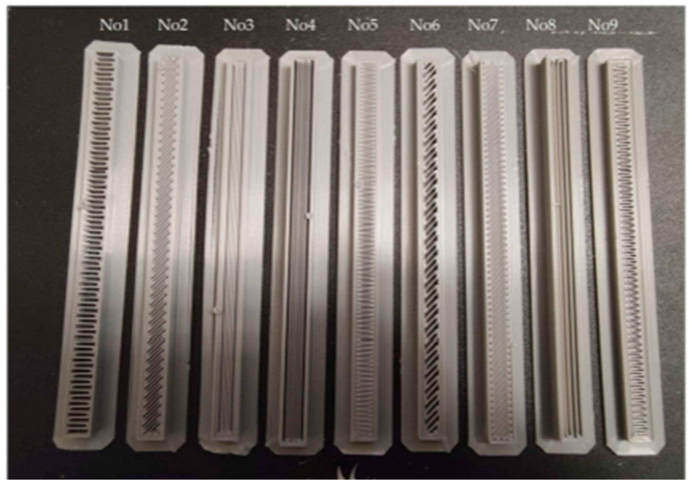
Such predictive models require a high quantity of input data to produce accurate outputs. During the development of the methodology and tool creation, there was a sufficient amount of data on the FFF technology, bending test method, and PLA material. Thus, all predictions were based on such data, which are presented in Table 2. Some of the specimens used for the bending test are visually presented in Figure 2. Figure 3 illustrates the bending test (a) conducted according to ASTM D790 [29] and the specimen after the test (b).
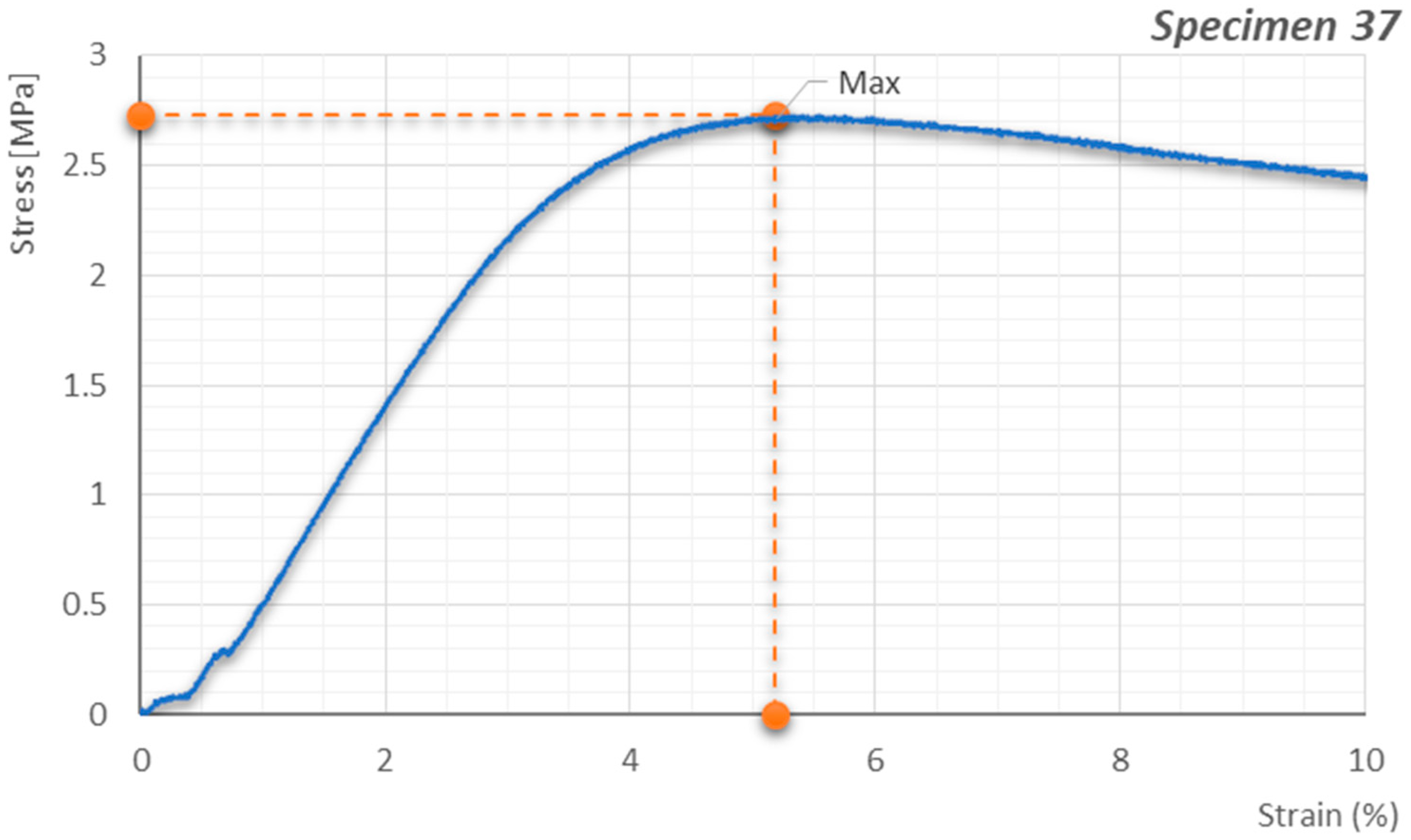
Each experiment was repeated five times, according to the ASTM standard. In Table 3, the three-point bending results are presented as average values along with their standard deviations. Stress and strain (Figure 4) produced by the experimental data and the Young’s modulus were calculated based on Equation (1):
w 0 = P   L 3 48   E   I
where w0 is the deflection (mm), P is the concentrated load (N) applied on the center of the beam, L is the distance between the two supports of the beam (mm), I is the second moment of area (mm4), and E is the Young’s modulus. The calculation of the I is based on Equation (2).
I = a 3 b 12
where a is the beam’s depth (mm), and b the beam’s width (mm). All bending specimens were square sections (□8 mm). Thus, by knowing the beam dimensions, experimentally measuring the central deflection and the applied force, it is possible to calculate the Young’s modulus E.
Considering that ANFIS models have a single output, three separate models were developed, each corresponding to one of the outputs.
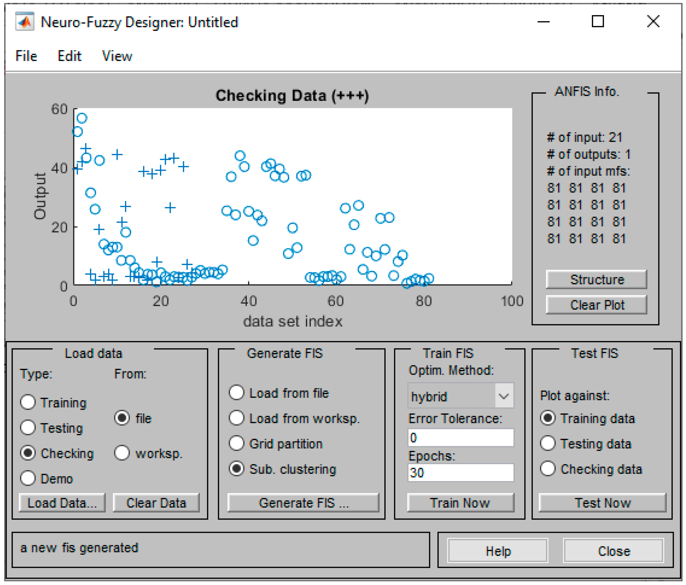
The fuzzy inference system (FIS) is generated following the Subtractive Clustering method [33], as suggested for systems with more than six input parameters. The training process for the ANFIS model involved preparing the experimental data by randomly splitting the data into training and validation sets. Figure 5 shows the scattering of the output values. Specifically, the training dataset is depicted as circles, and the checking dataset is depicted as pluses. For the generation of the initial model for ANFIS training, Subtractive Clustering is applied. Subtractive Clustering method groups the data in clusters based on the given range of influence. The system locates the center of each cluster and defines its effect according to that range.
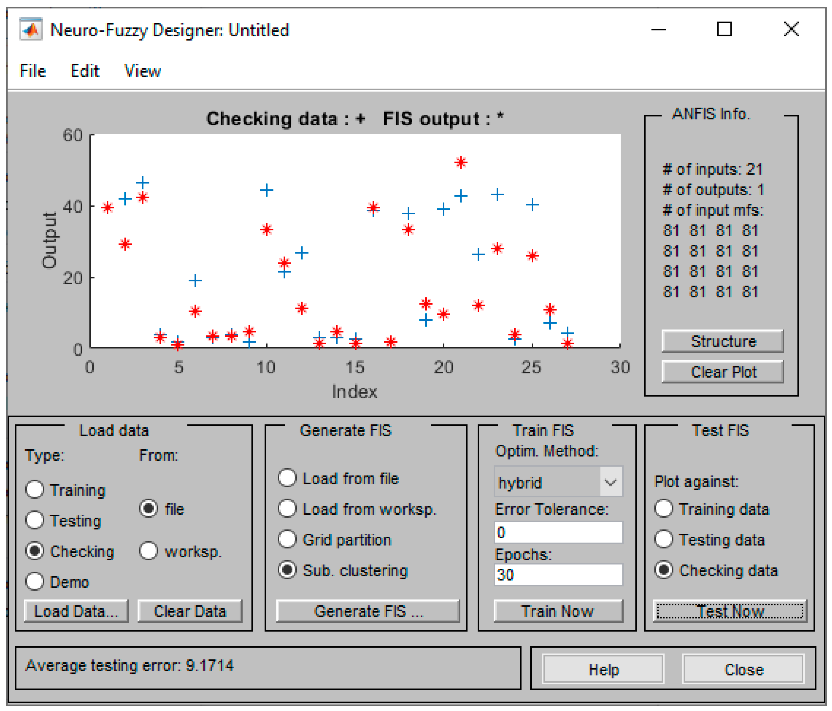
The model structure, combining fuzzy logic and neural networks, was trained using a hybrid learning algorithm that adjusts membership function parameters through least-squares and backpropagation gradient descent methods. Training continued for a specified number of epochs until the error converged to a relatively low value. The training error is calculated as the difference between the predicted output of the ANFIS model and the actual experimental value for each data point in the training set. The error calculation was performed using the Root Mean Square Error (RMSE) for both training and validation sets, providing a measure of the model’s performance and generalization capability. Figure 6 illustrates this process, showing the reduction in RMSE over successive epochs, indicating the model’s successful training and validation. Figure 6 shows the checking error as dots on top and the training error as asterisks on the bottom. The FIS test against the training data (Figure 7) revealed a well-trained system, but the test against the checking data (Figure 8) showed low performance. The RMSE of the model equals to 9.17, 20% within the range of the outputs, caused probably by the high number of the examined factors compared to the low number of the entries. Regarding the RMSE for strain and Young’s modulus, the values for the index error were correspondingly high (51% and 41% within the range of the data for each one, respectively).

3.3. The ANFIS Bending Model

Based on the analysis of the generic ANFIS model, a reduced focus on bending and PLA material was produced. This decision was motivated by the relatively higher number of experimental available data of these two inputs (PLA and bending).
The proposed bending model was based on the experimental data of FFF technology, bending test method, and PLA material. Thus, nine inputs were used, i.e., (1) Infill Pattern, (2) Infill Percentage, (3) Layer Thickness, (4) Speed, (5) Extruder Temperature, (6) Bed Temperature, (7) Position on Printer Bed, (8) Incline against Printer Bed, and (9) Raster Angle, as presented in Table 4.
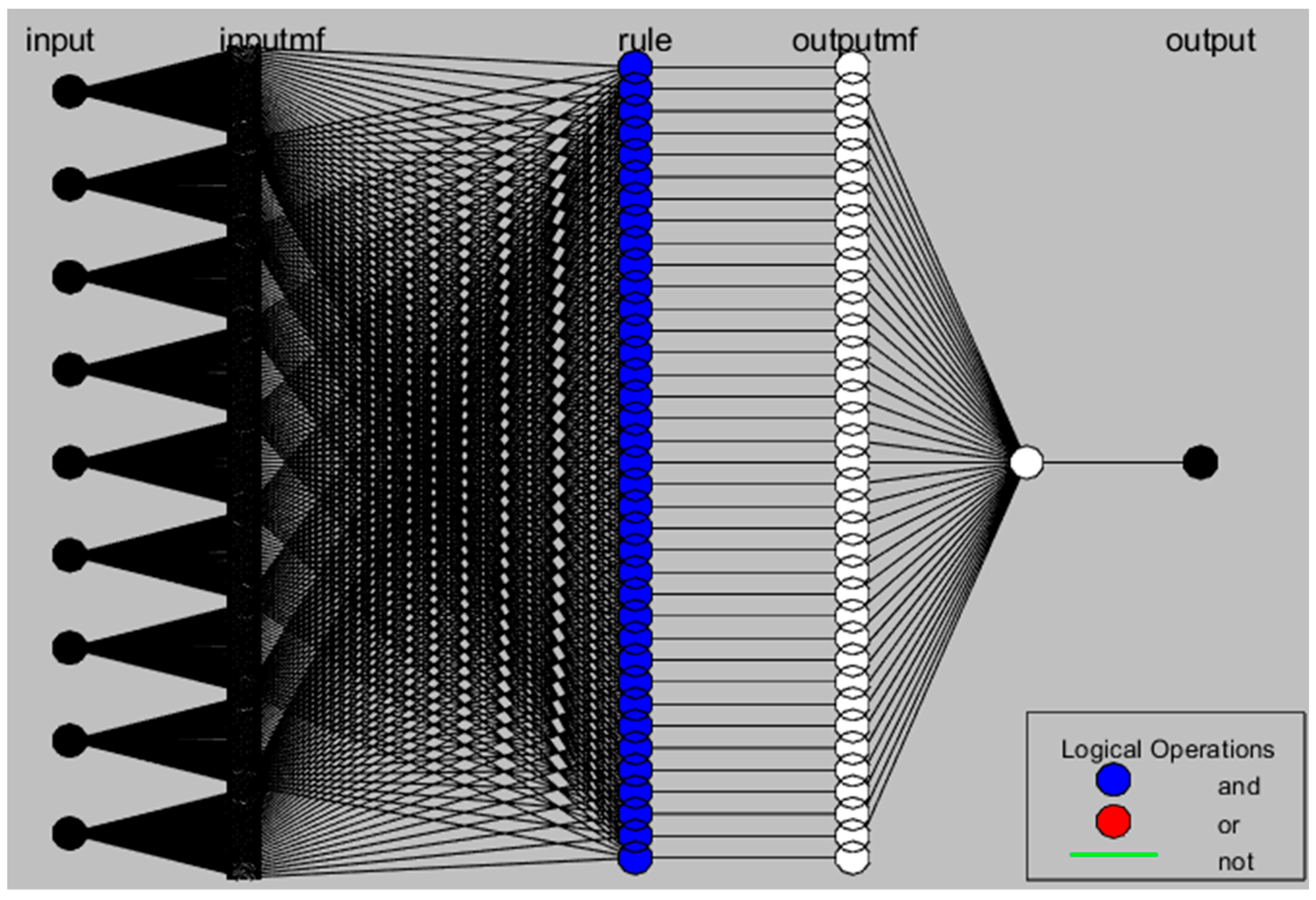
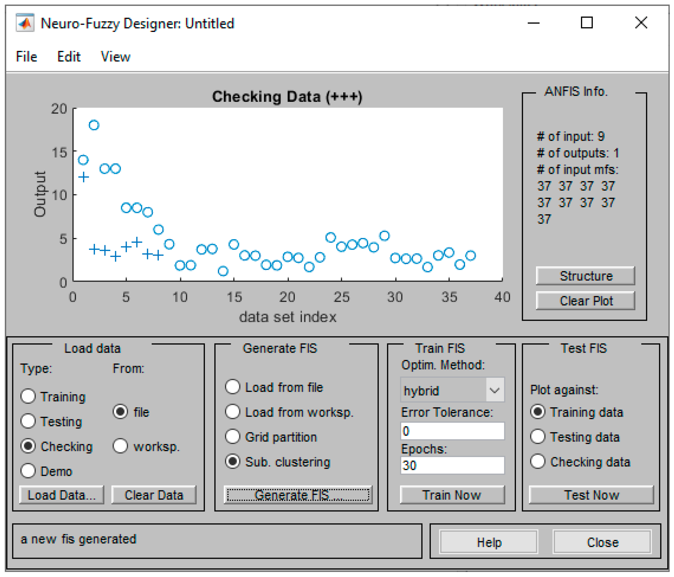
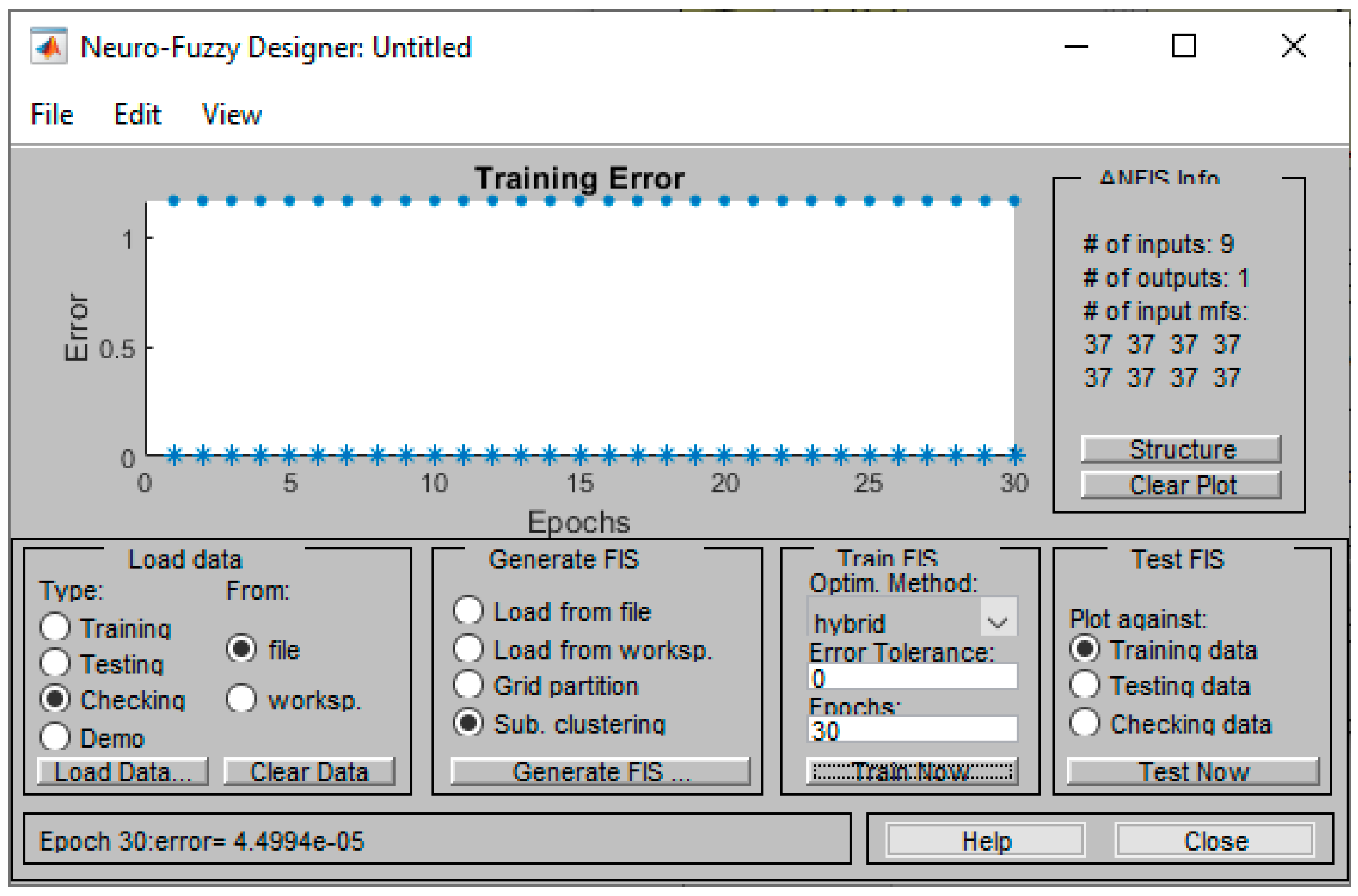
A further examination of the data revealed three areas where the responses vary from low to quite accurate. Taking this into account, a higher level of investigation on the settings of the FIS is conducted. Figure 9 illustrates the five processing layers and the connections between them within the structure of the ANFIS model. The dataset is divided into training (circles) and checking datasets (pluses), as depicted in Figure 10. Figure 11 shows that the system achieves the best convergence since the first epoch due to limited inputs, with the checking error depicted as dots on top and the training error as asterisks on the bottom.
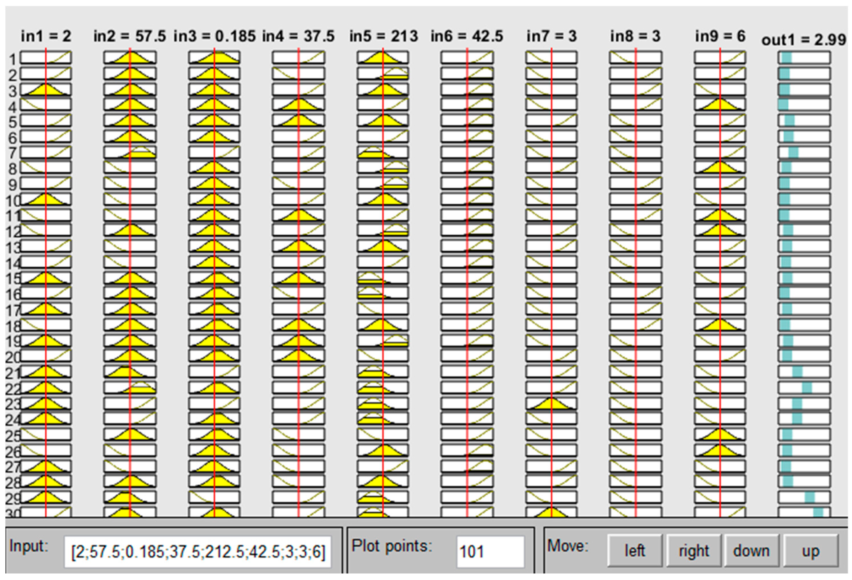
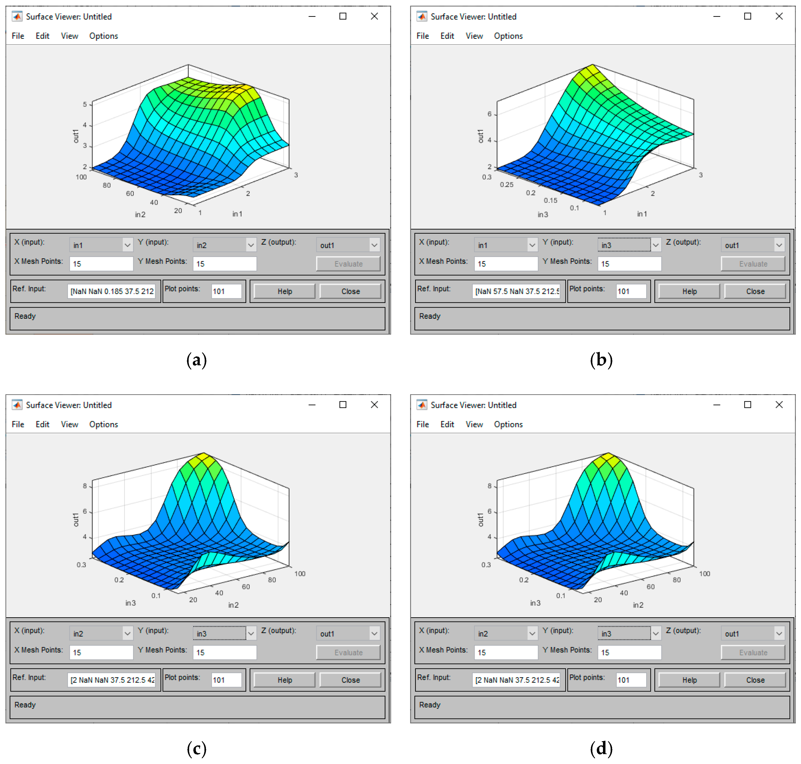
For a better understanding of Sugeno-type fuzzy rules, a pictorial view of fuzzy rules is presented in Figure 12. Figure 13 illustrates the surface plots that represent the mapping from the inputs to the outputs. Each surface plot indicates the correlation between two inputs and the output (maximum stress) expressed by different colors. Warmer colors like yellow indicate higher activation levels, while cooler colors like blue indicate lower activation levels. Finally, Figure 14 represents the experimental and predicted values for the maximum stress against the checking data. The maximum stress is equal to 1.17, which is compared to the range of the checking outputs equal to 9.75%.
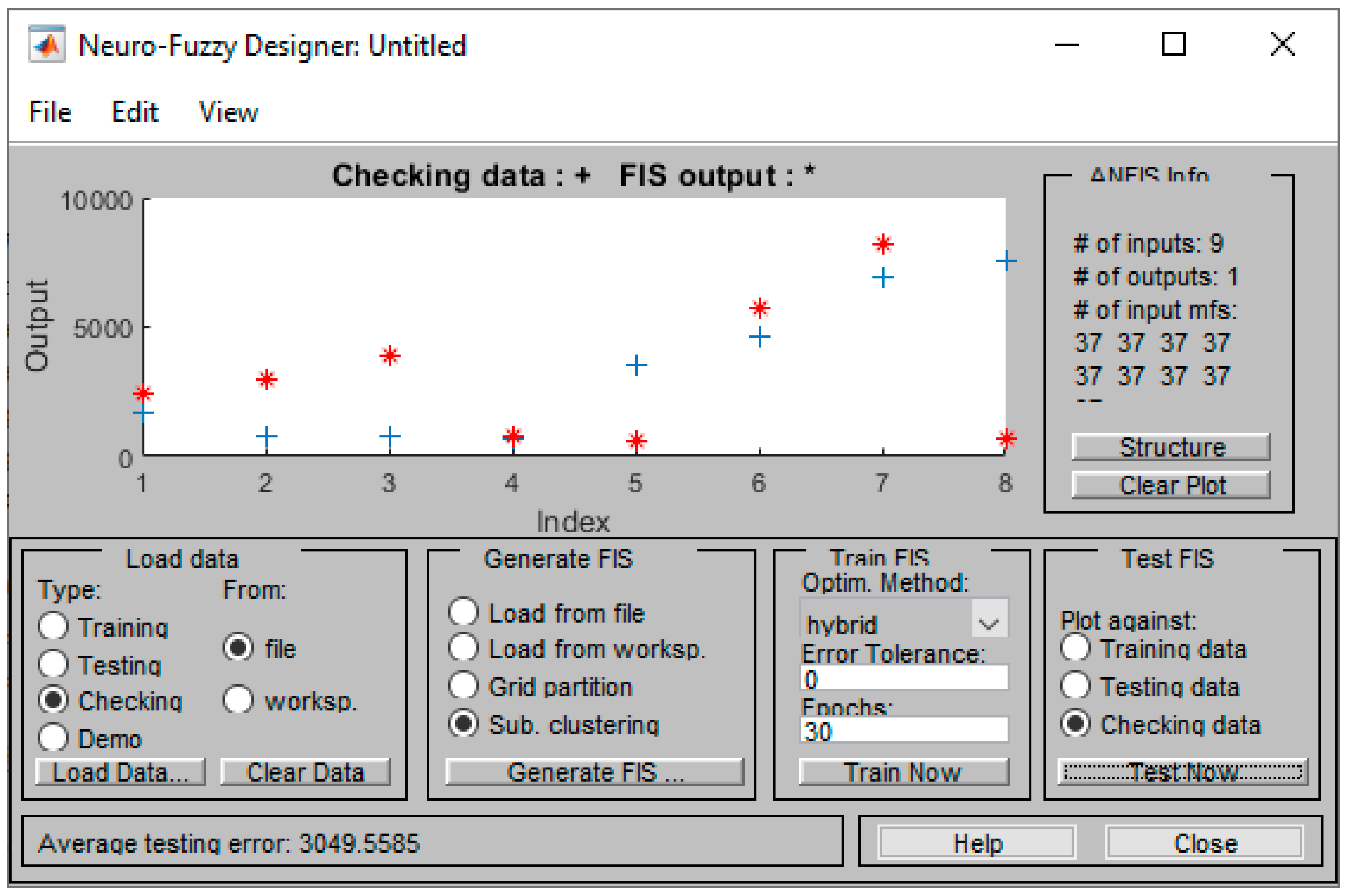
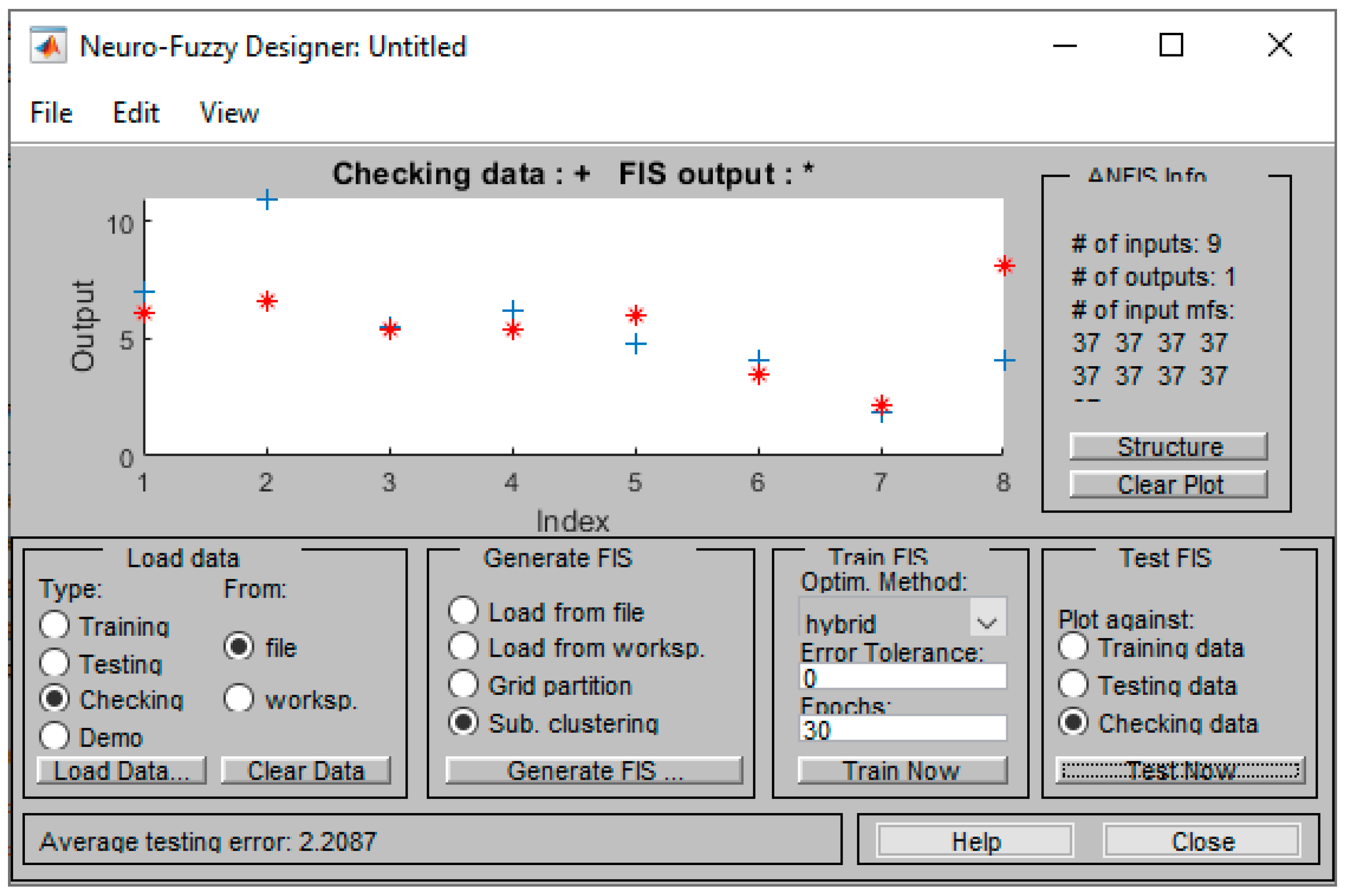
Similarly, two ANFIS models are developed for the strain and the Young’s modulus based on the same experiments. For both models, the training error equals to zero. Figure 15 and Figure 16 depict the experimental and predicted values for the two cases, respectively. Regarding the Young’s modulus, it equals to 3049 MPa, which reflects 40% of the data range. However, the strain equals to 2.21, reduced by 20% within the data range.

4. Analysis of Model Performance

The ANFIS generic model, developed for 21 inputs, showed inadequate performance, as expected, in achieving satisfactory results for the analyzed properties of the specimens. Although the training process showed excellent recognition of the correlations of the 3D printing parameters with the output values, the test against the checking data proved that the entries in the dataset are few to support the method. The resultant RMSE against checking data is 20%, 41%, and 51% within the range of data for maximum stress, Young’s modulus, and strain, respectively.
The ANFIS bending model, consisting of nine inputs, exhibited improved RMSE for maximum stress and strain, equal to 9.75% and 20%, respectively. The fact that the index for the Young’s modulus was 40% seems to be illusory. It could be evidence that the quantity of the available data was not adequate.
The observed difference in the modeling accuracy of stresses compared to Young’s modulus and strain can be explained by several factors. Firstly, stresses, particularly maximum stress, are more directly influenced by key input parameters such as infill density, layer height, and printing speed, which directly affect the load-bearing capacity and stress distribution within the material. In contrast, Young’s modulus and strain percentage are more sensitive to microstructural variations and intrinsic material properties, which may not be as effectively captured by the input parameters used. Additionally, the experimental measurement of maximum stress is typically more straightforward and less prone to error compared to Young’s modulus and strain, which can be influenced by small experimental errors and noise. The variability in the experimental data for Young’s modulus and strain can be higher due to the complex interactions between material properties and the printing process, introducing noise into the training data and making it more challenging for the model to learn accurate patterns. Lastly, the ANFIS model might be more adept at capturing the relatively simpler relationship between input parameters and maximum stress, whereas the relationships for Young’s modulus and strain might be more complex, leading to potential overfitting or underfitting issues. These considerations underscore the importance of refining input parameters and model structures to improve predictions for Young’s modulus and strain percentage.
As a concluding remark, the performance increases when using 9 input parameters compared to 21 input parameters. This is explained by the fact that two distinct models are developed in this study: one with 21 inputs designed to be more general, and another with 9 inputs specifically focused on bending. The general model with 21 inputs aims to capture a wide range of physical effects and is therefore applicable to a broader spectrum of AM technologies and materials. However, the data available for this model are less comprehensive, which can limit its performance. In contrast, the bending model with nine inputs is customized for specific parameters that directly influence the bending behavior of the samples. The data used for the bending model are more extensive, allowing for a more precise training process.
While it is true that reducing the number of input parameters may exclude certain physical effects, the selected parameters in the bending model are those most critical to capturing the mechanical behavior under bending conditions. This approach strikes a balance between model simplicity and accuracy, demonstrating that a focused, well-trained model can outperform a more general one with fewer but more relevant input parameters.

5. Conclusions

The main focus of this research aimed at establishing a novel, flexible method for predicting the mechanical properties of Additively Manufactured parts through Artificial Neural Networks and fuzzy logic. Two ANFIS models were developed, i.e., a generic model that requires additional experimental data from various AM technologies, materials, and mechanical tests, and a focused model specifically designed for predicting the mechanical properties of PLA specimens produced using FFF in bending tests.
In line with the objective of optimizing the AM fabrication process, the majority of the relevant studies typically focus and examine a limited number of parameters within the strict boundaries of the experiments. The innovative aspect of this research is the development of a predictive model capable of adapting to any AM technology and material, while considering the various process parameters that affect the maximum stress and strain and Young’s modulus of the final product.
The study highlights the performance improvement achieved by using 9 input parameters compared to 21 input parameters. This is due to the development of two distinct models: one with 21 inputs designed to be more general, and another with 9 inputs specifically focused on bending. The general model with 21 inputs aims to capture a wide range of physical effects and is therefore applicable to a broader spectrum of AM technologies and materials. However, the data available for this model are less comprehensive, which can limit its performance. In contrast, the bending model with nine inputs is customized for specific parameters that directly influence the bending behavior of the samples. The data used for the bending model are more extensive, allowing for a more precise training process.
Comparing the experimental results with the numerically modeled mechanical parameters, we observe a good correlation in certain aspects while identifying areas that require further refinement. The numerically predicted maximum stress and strain showed reasonable agreement with the experimental values, with RMSE values within 20% and 9.75%, respectively, suggesting that the model is fairly accurate for these parameters. However, the prediction for Young’s modulus exhibited a higher RMSE of approximately 40%, primarily due to one outlier with a significant deviation. This indicates that, while the model captures the general trend, the accuracy for Young’s modulus can be improved with additional data and potential refinement of the model.
The results of the developed systems revealed the potential of the method to provide successful predictions, highlighting the necessity for more input data. This would enable an accurate initial estimation of the applied AM process (including AM technologies, materials, structure settings, and process parameters), thereby avoiding the waste of crucial resources.
Despite the potential of this novel approach, it is clear that further experiments are necessary to enhance the model. Future experiments will enrich the dataset with results from different AM technologies, materials, and experimental studies. Given ANFIS’s proven capability to identify nonlinear relationships in the field of mechanical properties, it can be applied to other areas of research. For example, examining the surface quality of AM parts using ANFIS, while integrating the knowledge gained from this study, would be particularly interesting.
In conclusion, the developed ANFIS model shows great promise for predicting the mechanical properties of FFF-printed PLA specimens with high accuracy. The findings highlight the importance of optimizing input parameters to enhance model performance, providing a valuable tool for researchers and practitioners in the field of additive manufacturing. Future research will further validate the model with diverse datasets and investigate ways to include additional relevant parameters without sacrificing model simplicity and performance along with continuous addition of experimental data on all available AΜ technologies, materials, and types of experimental tests in mechanics.

Author Contributions

Conceptualization, V.D.S. and P.Z.; methodology, V.D.S., P.Z. and A.T.; validation, V.D.S., P.Z. and A.T.; formal analysis, A.T., P.Z. and V.D.S.; investigation, A.T., V.D.S. and P.Z.; resources, P.Z, V.D.S. and A.T.; data curation, V.D.S. and A.T.; writing—original draft preparation, A.T., V.D.S. and P.Z.; writing—review and editing, V.D.S., P.Z., A.T. and C.S.; visualization, A.T.; supervision, C.S. All authors have read and agreed to the published version of the manuscript.

Funding

This research received no external funding.

Data Availability Statement

Data are contained within the article.

Conflicts of Interest

The authors declare no conflicts of interest.

References

  1. Takagi, T.; Sugeno, M. Fuzzy identification of systems and its applications to modeling and control. IEEE Trans. Syst. Man Cybern. 1985, SMC-15, 116–132. [Google Scholar] [CrossRef]
  2. Jang, J.-S. ANFIS: Adaptive-network-based fuzzy inference system. IEEE Trans. Syst. Man Cybern. 1993, 23, 665–685. [Google Scholar] [CrossRef]
  3. ASTM F2792-12; Standard Terminology for Additive Manufacturing Technologies. ASTM International: West Conshohocken, PA, USA, 2012; Volume 1, p. 1.
  4. Ngo, T.D.; Kashani, A.; Imbalzano, G.; Nguyen, K.T.; Hui, D. Additive manufacturing (3D printing): A review of materials, methods, applications and challenges. Compos. Part B Eng. 2018, 143, 172–196. [Google Scholar] [CrossRef]
  5. Callı, M.; Albak, E.I.; Ozturk, F. Prediction and Optimization of the Design and Process Parameters of a Hybrid DED Product Using Artificial Intelligence. Appl. Sci. 2022, 12, 5027. [Google Scholar] [CrossRef]
  6. Ali, M.H.; Batai, S.; Sarbassov, D. 3D printing: A critical review of current development and future prospects. Rapid Prototyp. J. 2019, 25, 1108–1126. [Google Scholar] [CrossRef]
  7. Divjak, A.; Modrić, D.; Kovačić, I.; Cviljušac, V. Anisotropic Mechanical Properties of Materials in Stereolithographic Additive Manufacturing. Tech. Gaz. 2020, 27, 1748–1753. [Google Scholar]
  8. Khorasani, A.; Gibson, I.; Awan, U.S.; Ghaderi, A. The effect of SLM process parameters on density, hardness, tensile strength and surface quality of Ti-6Al-4V. Addit. Manuf. 2019, 25, 176–186. [Google Scholar] [CrossRef]
  9. Ramesh, M.; Panneerselvam, K. Mechanical investigation and optimization of parameter selection for Nylon material processed by FDM. Mater. Today Proc. 2021, 46, 9303–9307. [Google Scholar] [CrossRef]
  10. Abouelmajd, M.; Bahlaoui, A.; Arroub, I.; Zemzami, M.; Hmina, N.; Lagache, M.; Belhouideg, S. Experimental analysis and optimization of mechanical properties of FDM-processed polylactic acid using Taguchi design of experiment. Int. J. Simul. Multidiscip. Des. Optim. 2021, 12, 30. [Google Scholar] [CrossRef]
  11. Sagias, V.D.; Giannakopoulos, K.I.; Stergiou, C. Mechanical properties of 3D printed polymer specimens. Procedia Struct. Integr. 2018, 10, 85–90. [Google Scholar] [CrossRef]
  12. Polyzos, E.; Katalagarianakis, A.; Polyzos, D.; Van Hemelrijck, D.; Pyl, L. A multi-scale analytical methodology for the prediction of mechanical properties of 3D-printed materials with continuous fibres. Addit. Manuf. 2020, 36, 101394. [Google Scholar] [CrossRef]
  13. Kumar Mishra, P.; Senthil, P. Prediction of in-plane stiffness of multi-material 3D printed laminate parts fabricated by FDM process using CLT and its mechanical behaviour under tensile load. Mater. Today Commun. 2020, 23, 100955. [Google Scholar] [CrossRef]
  14. Yadav, D.; Chhabra, D.; Gupta, R.K.; Phogat, A.; Ahlawat, A. Modeling and analysis of significant process parameters of FDM 3D printer using ANFIS. Mater. Today Proc. 2020, 21, 1592–1604. [Google Scholar] [CrossRef]
  15. Mehrpouya, M.; Gisario, A.; Rahimzadeh, A.; Nematollahi, M.; Baghbaderani, K.S.; Elahinia, M. A prediction model for finding the optimal laser parameters in additive manufacturing of NiTi shape memory alloy. Int. J. Adv. Manuf. Technol. 2019, 105, 4691–4699. [Google Scholar] [CrossRef]
  16. Mohamed, O.A.; Xu, W. Comment about lack of sufficient data on “A prediction model for finding the optimal laser parameters in additive manufacturing of NiTi shape memory alloy” by Mehrpouya et al. [The International Journal of Advanced Manufacturing Technology 105.11 (2019): 4691–4699.]. Prog. Addit. Manuf. 2021, 7, 435–442. [Google Scholar]
  17. Dhar, A.R.; Gupta, D.; Roy, S.S. Development of a bi- directional multi- input- multioutput predictive model for the fused deposition modelling process using co-active adaptive neurofuzzy inference system, IOP Conference Series. Mater. Sci. Eng. 2021, 1136, 12007. [Google Scholar] [CrossRef]
  18. Abate, K.M.; Nazir, A.; Jeng, J.-Y. Design, optimization, and selective laser melting of vin tiles cellular structure-based hip implant. Int. J. Adv. Manuf. Technol. 2021, 112, 2037–2050. [Google Scholar] [CrossRef]
  19. Hu, Z.; Mahadevan, S. Uncertainty quantification in prediction of material properties during additive manufacturing. Scr. Mater. 2019, 135, 135–140. [Google Scholar] [CrossRef]
  20. Dev, S.; Srivastava, R. Experimental investigation and optimization of FDM process parameters for material and mechanical strength. Mater. Today Proc. 2017, 26, 1995–1999. [Google Scholar] [CrossRef]
  21. Zacharia, P.T. An Adaptive Neuro-fuzzy Inference System for Robot Handling Fabrics with Curved Edges towards Sewing. J. Intell. Robot Syst. 2010, 58, 193–209. [Google Scholar] [CrossRef]
  22. Azad, A.; Karami, H.; Farzin, S.; Saeedian, A.; Kashi, H.; Sayyahi, F. Prediction of Water Quality Parameters Using ANFIS Optimized by Intelligence Algorithms (Case Study: Gorganrood River). KSCE J. Civ. Eng. 2018, 22, 2206–2213. [Google Scholar] [CrossRef]
  23. Vakhshouri, B.; Nejadi, S. Prediction of compressive strength of self-compacting concrete by ANFIS models. Neurocomputing 2018, 280, 13–22. [Google Scholar] [CrossRef]
  24. Ly, H.-B.; Pham, B.T.; Dao, D.V.; Le, V.M.; Le, L.M.; Le, T.-T. Improvement of ANFIS Model for Prediction of Compressive Strength of Manufactured Sand Concrete. Appl. Sci. 2019, 9, 3841. [Google Scholar] [CrossRef]
  25. El-Hasnony, I.M.; Barakat, S.I.; Mostafa, R.R. Optimized ANFIS Model Using Hybrid Metaheuristic Algorithms for Parkinson’s Disease Prediction in IoT Environment. IEEE Access 2020, 8, 119252–119270. [Google Scholar] [CrossRef]
  26. Saleh, M.; Anwar, S.; Al-Ahmari, A.M.; AlFaify, A.Y. Prediction of Mechanical Properties for Carbon fiber/PLA Composite Lattice Structures Using Mathematical and ANFIS Models. Polymers 2023, 15, 1720. [Google Scholar] [CrossRef]
  27. ASTM D638-14; Standard Test Method for Tensile Properties of Plastics. ASTM International: West Conshohocken, PA, USA, 2014; Volume 1, p. 1.
  28. ASTM D695-15; Standard Test Method for Compressive Properties of Rigid Plastics. ASTM International: West Conshohocken, PA, USA, 2015; Volume 1, p. 1.
  29. ASTM D790-17; Standard Test Methods for Flexural Properties of Unreinforced and Reinforced Plastics and Electrical Insulating Materials. ASTM International: West Conshohocken, PA, USA, 2017; Volume 1, p. 1.
  30. ASTM D3039; Standard Test Method for Tensile Properties of Polymer Matrix Composite Materials. ASTM International: West Conshohocken, PA, USA, 2014; Volume 1, p. 1.
  31. ASTM D5279-21; Standard Test Method for Plastics: Dynamic Mechanical Properties: In Torsion. ASTM International: West Conshohocken, PA, USA, 2021; Volume 1, p. 1.
  32. ASTM D7791-17; Standard Test Method for Uniaxial Fatigue Properties of Plastics. ASTM International: West Conshohocken, PA, USA, 2017; Volume 1, p. 1.
  33. Srisaeng, P.; Baxter, G. Predicting Australia’s Domestic Airline Passenger Demand using an Anfis Approach. Transp. Telecommun. 2022, 23, 151–159. [Google Scholar] [CrossRef]
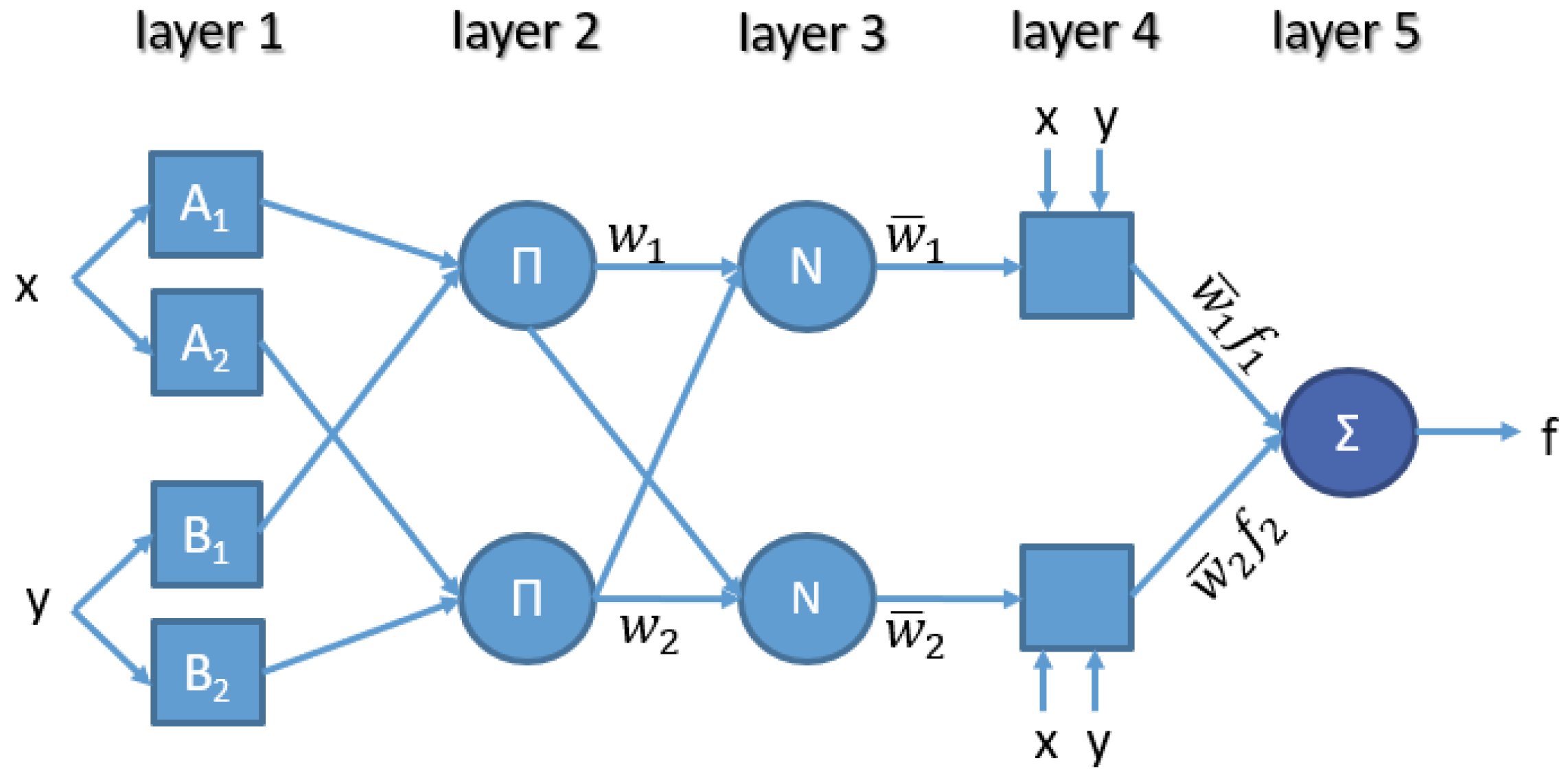
Figure 1. ANFIS architecture.
Machines 12 00523 g001
Figure 2. One group of specimens used for bending.
Machines 12 00523 g002
Figure 3. Bending test on PLA material manufactured by FFF: (a) bending test and (b) bending specimen after test.
Machines 12 00523 g003
Figure 4. Stress–strain curve of experiment 37 (indicative).
Machines 12 00523 g004
Figure 5. Data for 21 input variables.
Machines 12 00523 g005
Figure 6. Training process of the ANFIS.
Machines 12 00523 g006
Figure 7. Testing error against training data (maximum stress).
Machines 12 00523 g007
Figure 8. Error against checking data (maximum stress).
Machines 12 00523 g008
Figure 9. ANFIS model structure.
Machines 12 00523 g009
Figure 10. Data for 9 input variables.
Machines 12 00523 g010
Figure 11. Training process of the ANFIS.
Machines 12 00523 g011
Figure 12. Fuzzy rule activation.
Machines 12 00523 g012
Figure 13. Surface plots against maximum stress between (a) Infill Pattern and Infill Percentage, (b) Infill Pattern and Layer Thickness, (c) Infill Percentage and Layer Thickness, and (d) Infill Percentage and Extruder Temperature.
Machines 12 00523 g013
Figure 14. Comparison between experimental and predicted values against checking data (maximum stress).
Machines 12 00523 g014
Figure 15. Comparison between experimental and predicted values against checking data (Young’s modulus).
Machines 12 00523 g015
Figure 16. Comparison between experimental and predicted values against checking data (strain).
Machines 12 00523 g016
Table 1. All initial parameters/model inputs of ANFIS generic model.
Input/FactorNumber of LevelsLevelsLevel Code
Input 1 */AM Technology4 discrete valuesFFF/FDM1
SLA2
SLS3
DED4
Input 2 */Testing Method3 discrete valuesBending1
Tensile2
Torsion3
Input 3 */Material 8 discrete valuesABS + PLA1
PLA2
ABS3
Resin Pro CR4
ABS +5
PETG6
SUS316L7
Ti8
Input 4 */Infill Pattern6 discrete valuesRectilinear1
Triangle2
Honeycomb3
Spiral4
Cross5
Diamond 6
Input 5 */Infill PercentageContinuous
(Range values)
Lower Level 0%
Higher Level 100%
As input
Input 6 */Layer ThicknessContinuous
(Range values)
Lower Level
Higher Level
As input
Input 7 */Wall ThicknessContinuous
(Range values)
Lower Level
Higher Level
As input
Input 8/SpeedContinuous
(Range values)
Lower Level
Higher Level
As input
Input 9/Extruder TemperatureContinuous
(Range values)
Lower Level
Higher Level
As input
Input 10/Laser Power RatioContinuous
(Range values)
Lower Level 0%
Higher Level 100%
As input
Input 11/Bed Temperature Continuous
(Range values)
Lower Level 0 °C
Higher Level 100 °C
As input
Input 12 */Position on Printer Platform6X1
X + 30°2
X + 45°3
X + 60°4
X + 90°5
Y6
Input 13 */Inclination against Printer Platform6On table1
On table +30°2
On table +45°3
On table +60°4
On table +90°5
Vertical6
Input 14 */Twist Angle around Center of Gravity axis2On table1
On table +90°2
Input 15 */Raster Angle71
90°2
0°/90°3
90°/0°4
30°/0°/−30°5
45°/−45°6
0°/120°/240°7
Input 16/Layers for Altering Raster Angle (Block)7Per 1 layer1
Per block—2 layers2
Per block—3 layers3
Per block—4 layers4
Per block—5 layers5
Per block—6 layers6
Per block—7 layers7
Input 17/Percentage of First MaterialContinuous
(Range values)
Lower Level 0%
Higher Level 100%
As input
Input 18/Curing TimeContinuous
(Range values)
Lower Level
Higher Level
As input
Input 19/Curing Power4 discrete values00
UT11
UT22
UT33
Input 20/Layer Composition2Sandwich1
Wave2
Input 21/Cross-Section3 discrete valuesRectangle1
Dogbone2
Circle3
* Mandatory input.
Table 2. Three-point bending experimental data—printing parameters.
S/NInfill PatternInfill (%)Layer Thickness (mm)Speed (mm/s)Temperature (°C)Bed Temperature (°C)Position on BedTwist Angle (°)Inclination (°)
12500.075020060115
22750.075020060315
331000.185020060517
42750.185020060515
521000.185020060115
63500.185020060317
721000.35020060315
82500.35020060515
93750.35020060117
101600.182521555116
113600.183821555517
122600.185021555155
133600,182523055157
142600.183823055115
151600.185023055516
162600.182524555515
171600.183824555156
183600.185024555117
191150.182521555116
203150.183821555517
212150.185021555155
223150.182523055157
232150.183823055115
241150.185023055516
252150.182524555515
261150.1837.524555156
273150.185024555117
281150.182518025116
293150.183818025517
302150.185018025155
313150.182519525157
322150.1837.519525115
331150.185019525516
342150.182521025515
351150.183821025156
363150.185021025117
371600.182518060116
383600.1837.518060517
392600.185018060155
403600.182519560157
412600.1837.519560115
421600.185019560516
432600.182521060515
441600.1837.521060156
453600.185021060117
Table 3. Three-point bending experimental data—results.
S/NStress Average
(MPa)
Stress Standard DeviationStrain
Average
(%)
Strain Standard DeviationYoung’s Modulus
(GPa)
114.001.105.800.626.03
212.000.677.000.524.29
313.000.665.000.716.50
413.000.608.500.723.82
58.500.415.000.454.25
618.000.626.000.777.50
78.500.345.000.244.25
88.000.782.500.498.00
96.000.734.500.583.33
103.200.452.500.423.20
114.000.413.400.643.02
121.000.350.820.683.20
132.000.351.500.493.59
143.000.422.450.743.38
154.000.423.000.663.76
162.000.571.500.623.85
171.500.241.000.424.43
184.000.443.450.323.51
193.750.702.500.644.64
204.000.552.500.475.06
212.500.471.600.565.05
222.000.231.200.385.51
234.000.402.600.445.20
243.000.511.950.595.31
254.000.482.500.575.64
261.500.331.050.475.14
274.000.532.550.545.77
284.080.754.780.492.14
295.090.624.510.772.82
304.030.801.860.835.41
314.270.521.850.425.77
324.530.794.440.552.55
334.450.674.330.652.57
343.961.044.280.982.32
353.130.751.900.534.12
365.290.544.700.622.81
372.730.835.180.920.74
382.640.763.750.810.99
392.660.482.770.391.35
401.690.522.800.640.85
413.030.624.630.520.92
422.980.624.800.580.87
433.360.833.820.781.24
441.980.402.530.371.10
453.010.704.900.690.86
Table 4. Datasheet of the ANFIS bending model.
Infill PatternInfill (%)Layer Thickness (mm)Speed (mm/s)Temperature (°C)Bed Temperature (°C)Position on BedTwist angle (°)Inclination (°)
2500.15020060115
2750.15020060315
31000.15020060517
2750.25020060515
21000.25020060115
3500.25020060317
21000.35020060315
2500.35020060515
3750.35020060117
Disclaimer/Publisher’s Note: The statements, opinions and data contained in all publications are solely those of the individual author(s) and contributor(s) and not of MDPI and/or the editor(s). MDPI and/or the editor(s) disclaim responsibility for any injury to people or property resulting from any ideas, methods, instructions or products referred to in the content.