1. Introduction
In the field of metal engineering, there is an increasing demand for castings with better mechanical and special properties, such as resistance to abrasive wear or resistance to corrosion at elevated temperatures [
1,
2,
3]. Castings for this purpose are often manufactured entirely from expensive materials based on Ni, Co, Ti, or other alloying elements. But in many cases, high-performance properties are only necessary for the working surface layer of the molded components [
4]. It is important to note that the wear limits of parts vary within a wide range, depending on a number of factors, and can vary from 100 to 200 µm to several mm. However, in practice, they do not exceed 5 mm.
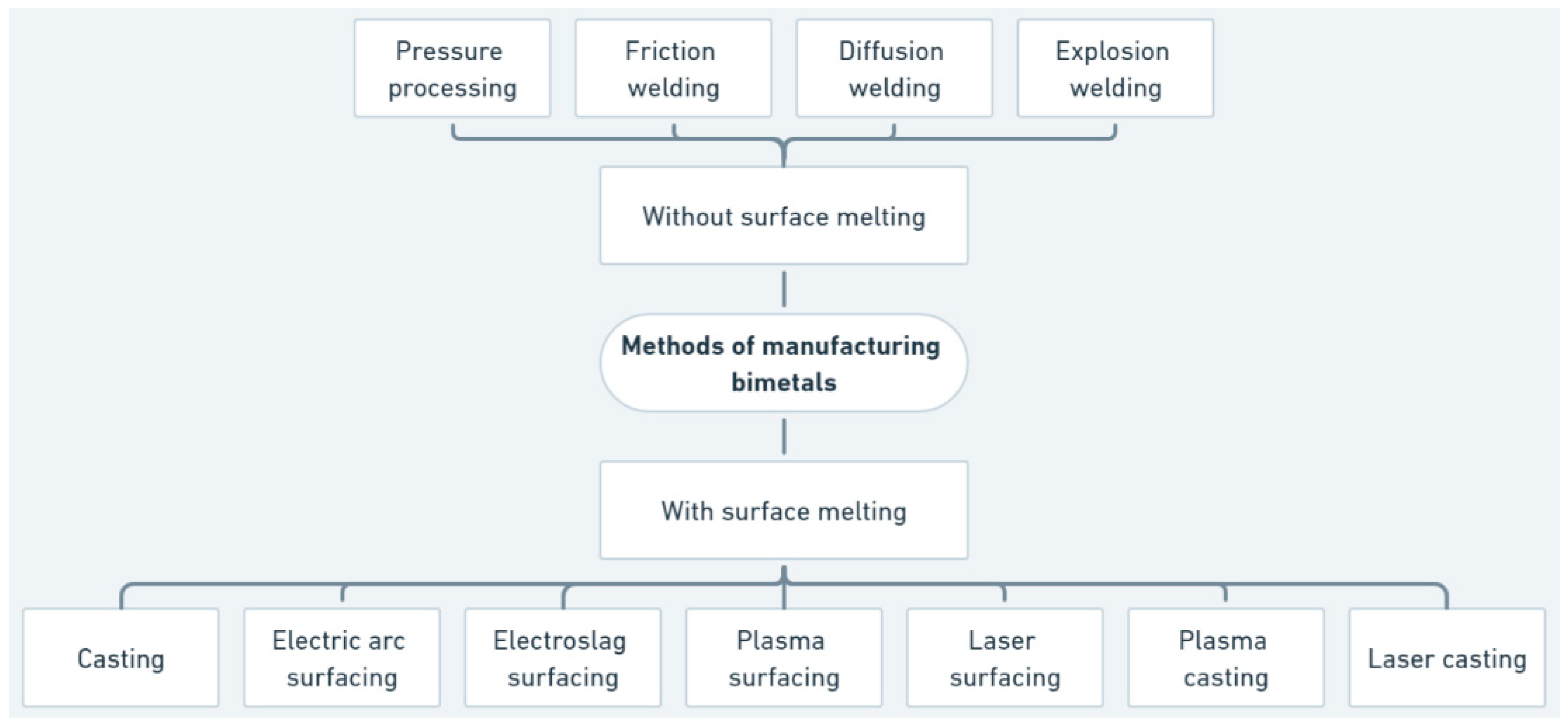
There are several basic processes for manufacturing multilayer and bimetallic materials in the metal industry (
Figure 1) [
5,
6,
7], including gas flame, plasma, and detonation spraying, as well as vacuum and electrolytic deposition. These methods are known for their high productivity and the wide range of materials they are applicable to. In recent years, plasma technologies for the application of functional bilayer coatings have become significantly widespread, especially in the metallurgical industry. However, they have several substantial drawbacks: the adhesion strength of such coatings to the base material does not exceed 15–20 kg/mm
2; the thickness of high-quality coatings is limited; and they cannot be used for parts that operate under conditions of hydro-, gas-, and impact-abrasive wear or cyclic alternating loads [
8,
9,
10].
The method of explosive welding for manufacturing bimetallic components is the most common in the industry for producing bimetals that include both homogeneous (alloyed, corrosion-resistant, heat-resistant, non-alloy steel) and heterogeneous (aluminum-copper, steel-copper) components. This process is characterized by a high productivity and strong adhesion between components due to diffusion processes, low production costs, a wide range of bimetals, and ease of production organization. However, it also has certain drawbacks such as a low process controllability and the uneven adhesion strength of bimetal components, especially over large areas, as well as high levels of noise and vibrations, which require additional protective measures [
11,
12].
One of the oldest and most cost-effective processes for producing layered metals is casting technology, which can be competitive with other widely used technologies such as cladding and thermal spraying [
13,
14,
15]. Casting is popular because this technology not only provides economic benefits but also prevents the initiation and growth of a heat-affected zone, which can occur in the final products when other layering methods are applied. Numerous publications focus on innovations, technology enhancements, and the investigation of bimetallic material properties [
16,
17,
18].
The research paper [
19] talks about a new technology for bimetallic layered castings that uses a method of layering a coating directly in the casting process (method of mold cavity preparation). This is the cheapest way to improve the surfaces of castings because the element that will be the working surface layer of the casting is put into the mold as a solid or granular insert before the molten metal is poured in. Austenitic steel (X10CrNi 18-8 steel) forms the surface layer (working part) of prepared casting examples, while a typical foundry material (ferritic-pearlitic carbon-cast steel) forms the substrate (bearing part). The microstructure and mechanical properties of prepared bimetallic layered castings have been studied using metallography, non-destructive ultrasonic testing, and hardness testing. Studies have found that using a pouring temperature of 1650 °C and carbon-cast steel with a concentration of 0.6% on the bearing part of bimetallic layered casting makes it possible for this material to join well with alloy steel X10CrNi 18-8.
The study carried out in [
18] investigates a very similar process for manufacturing bimetallic castings from pearlitic gray cast iron and different alloy steels [
20] (high chromium steel X16Cr13, chromium-nickel austenitic steel X10CrNi18-8, or duplex ferritic-austenitic steel X2CrNiMoN22-5-3). The steel part is placed in the casting mold just before the pearlitic gray cast iron, which forms the bearing part, is poured. In this case, steel plates with a thickness of 5 mm were used, and the surfaces that were in contact with the molten metal were covered with an activator in the form of boron and sodium. These compounds facilitate the formation of a bimetallic joint. The thickness ratio between the bearing and working parts is about 8:1. The proposed founding technology, which is based on a mold cavity preparation method, enables the creation of bimetallic layered castings in various configurations. These configurations include a bearing part made of pearlitic gray cast iron, a working part (layer) made of high-chromium ferritic or martensitic alloy steel, or a chromium–nickel austenitic or duplex ferritic–austenitic alloy. Furthermore, these castings are free from defects, particularly in the sensitive area of the joint between both materials. The permanent joint that was made between the steel plate and the gray cast iron is characterized by diffusion, which is mostly caused by carbon moving from the cast iron to the steel.
One publication [
21] has studied the possibility of obtaining bimetals through continuous horizontal casting when the composition of components occurs in a liquid state without mixing. Binary mixtures of the eutectic-type bimetals Al-Zn, Al-Sn, and Al-Pb were selected, and contact layers of the composite metals were investigated using metallographic, X-ray diffraction, microscopic, and ultrasonic analyses. It was established that the size of the diffusion zone of the interface layer for the production of bimetallic compositions through the direct connection of liquid-phase components was 0.1–0.5 mm.
Despite the achievements in [
18,
19,
20,
21,
22,
23], manufacturing high-quality bimetallic products using this method is a difficult task in practice. In this case, the bonding of bimetal layers occurs after pouring, which leads to the formation of oxide films that can worsen the adherence of the layers.
Methods to modify the surface of solid substrates significantly impact the structure and mechanical properties of bimetallic materials.
Laser treatment is used to create a regular macroroughness on the substrate’s surface. This promotes better adhesion between the metal layers by altering the structure and increasing the number of grain boundaries and defects, which enhances the diffusion of elements between the layers. It significantly influences mechanical properties by improving the adhesion and wear resistance of the materials [
24].
Explosive welding is used to join two metals through an explosion, causing plastic deformation and welding. It forms a wavy structure at the boundary between the layers, which improves mechanical stability. This method affects the mechanical properties of the alloys by increasing adhesion strength and resisting delamination [
11].
Plasma spraying allows for the creation of high-quality coatings with various properties. Its structure ensures a uniform distribution of particles and micropores. This process also changes mechanical properties, increasing hardness and wear resistance, but may reduce impact toughness [
25].
The primary aim of this study is to enhance the process of manufacturing bimetallic materials by combining laser treatment with traditional casting methods to achieve superior mechanical and structural properties. This research focuses on optimizing the process parameters, including the melt-to-solid phase ratios and pouring temperatures, to produce high-quality bimetallic castings with improved thermal, corrosion, and wear resistance. As part of the experiment, alloy-grade nickel UNS 6230 plates are treated with a laser to make a regular macro-relief on their surface.
3. Methodology for Bimetal Manufacturing
To apply a regular macro-relief to the surface of the plates of the functional material with dimensions of 100 × 50 × 4 mm, the technological laser complex Aramis LTC75 (Ukraine) was used. Process parameters: P = 400–500 W, S = 1–2 m/min, p = 2–3 atm, d = 0.4–0.5 mm.
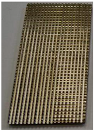
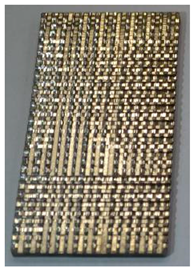
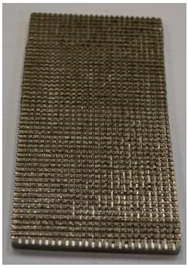
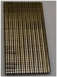
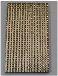
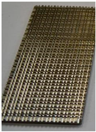
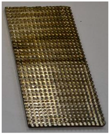
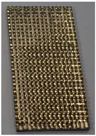
On the surface of the plates, a regular macro-relief in the form of square-shaped protrusions with cross dimensions of 1 × 1 mm was fabricated through radiation with a fiber laser in the evaporation mode, combined with mechanical processing. The height of the protrusions on all samples was h = 0.5; 1.0; 1.5 mm, with the spacing between protrusions along two coordinates being 1.0; 1.5, and 2.0 mm (
Table 4). The height and spacing between the protrusions were chosen based on previous research. FEA modeling showed that these protrusion arrangements are optimal for the uniform distribution of temperature in the functional layer due to the contact area, based on the size, area, and configuration of the protrusions themselves [
33].
The melted structural component, grade S235JRG2 steel, was poured into a sand mold where plates made of nickel alloy UNS 6230, treated on the pouring side, were fixed.
Green sand was used in the mold, which is a mixture of silica sand, clay (bentonite), and water. This type of mold was chosen for its ease of preparation and low cost. Green sand has a high moisture content, which allows it to retain shape when filled with molten metal, and it also has a good thermal stability. Additionally, a graphite coating was utilized as a molding layer due to its favorable properties and relatively low cost.
The melt temperature was maintained at 1600 °C, as measured by a tungsten–rhenium thermocouple. To ensure sufficient thermal conductivity and mold stability during the pouring of the molten metal, the mold was preheated in a drying oven at 300 °C for 4 h. After the pouring process was completed, the samples and the mold were cooled for 4 h until the mold and the castings reached room temperature (20 °C). Gradual cooling minimizes internal stresses in the material, reduces the risk of cracks or other defects, and ensures the dimensional stability of the obtained bimetallic blanks.
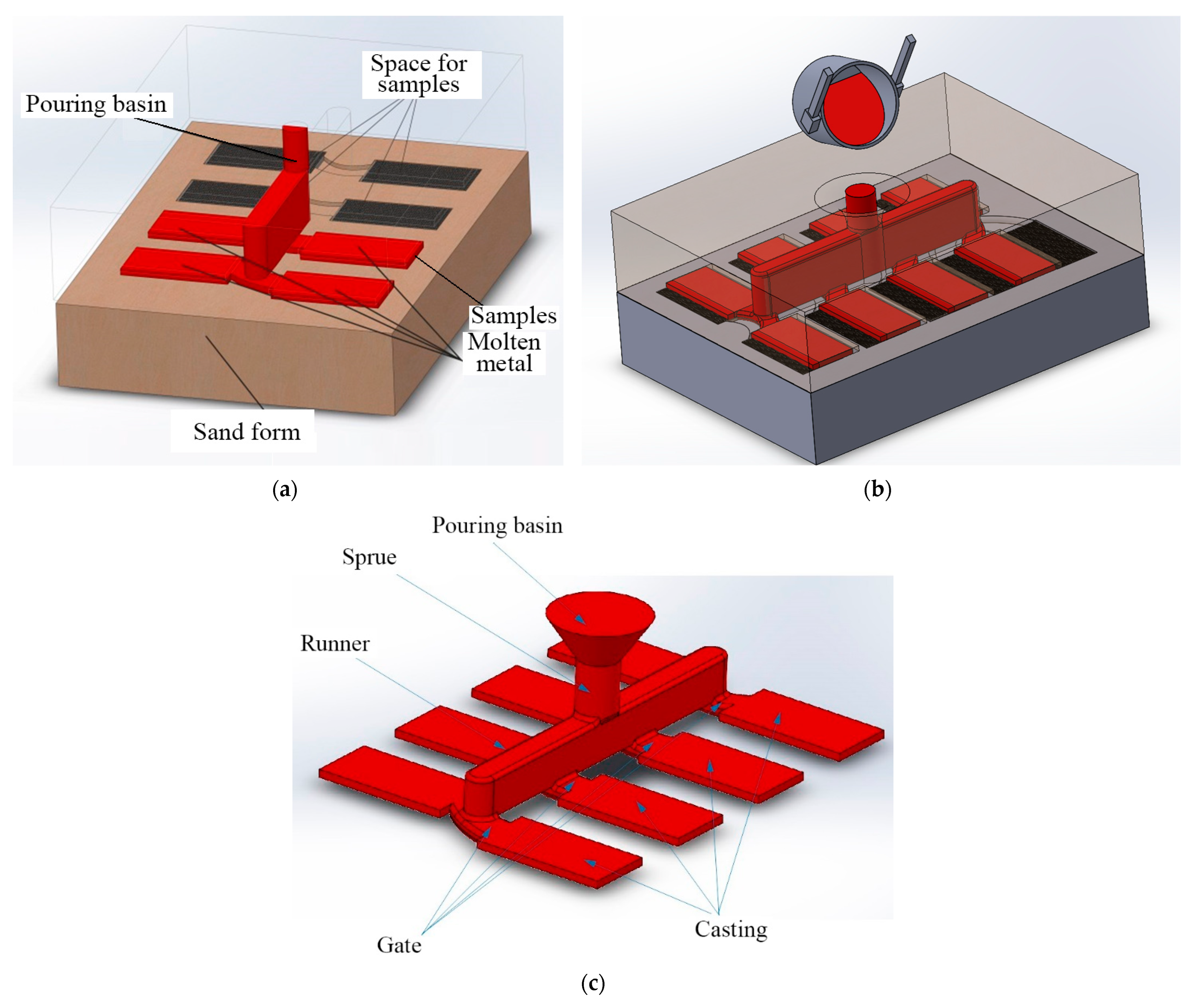
Technological and schematic view of the bimetallic casting process.
Samples made of nickel alloy were placed in a sand mold (
Figure 2), after which they were heated to a temperature of 300 °C and maintained in the furnace for 3 h. The melted structural component of the bimetal, steel S235JRG2, preheated to a temperature of 1600 °C, was applied to the surface of the samples through a separate gating system. After casting, the samples and the mold were cooled for 4 h. The carbon concentration in the S235JRG2 steel was 0.30 wt%.
The principles for reducing turbulence are a smooth flow, adequate sprue height, and optimized gate design. They should also be tapered to reduce pressure and turbulence. The non-pressurized gating system consists of (
Figure 2c) a sprue (area 40 × 30 mm), runner (area 280 × 30 × 22 mm), ingates (area 6 × 30 mm).
4. Methodology for Samples Analysis
For the microstructure analysis, all specimens were cut using the EDM method. The primary cutting line was a vertical cut along the center of the 100 mm length. In addition, smaller sections were cut off both sides near the central part.
To reveal the microstructure, microsection samples were prepared, which were subjected to etching with a specialized “Murakami” solution and a 3% solution of nitric acid in ethyl alcohol. Subsequently, the microsections were rinsed with water and alcohol and dried with filter paper.
To determine the phase composition of the obtained bimetals, X-ray diffraction analysis was conducted using the “Theta-2-Theta” method on a Rigaku Ultima IV X-ray diffractometer with a graphite monochromator in copper radiation CuKα = 0.15418 nm (Rigaku Corp., Tokyo, Japan). Voltage: 30 kV; current strength: 30 mA; slit width that limits the X-ray beam: 6 mm. In the study, the Bragg–Brentano focusing scheme was used. Research conditions: angle range 2-Theta = 25–140°; shooting step—0.04°; exposure time at point—2 s; duration of shooting one sample—90 min.
An analysis of the obtained X-ray spectra and quantitative and qualitative phase analyses were performed using the PDXL software (version 2.9), the International Centre for Diffraction Data (ICDD, PDF-2), and the open Crystallographic Data Database (COD).
The features of the formation of the joining zone of bimetal components were studied using an REM-106I (Ukraine) scanning electron microscope with an energy-dispersive microanalysis system (EDX). The main characteristics of the device include the following: vacuum up to 5 × 10⁻⁶ mm Hg; accelerating voltage from 0.5 to 30 kV; resolution in secondary electrons in high vacuum mode: 4 nm; and in low vacuum mode: 6 nm; tungsten (W) cathode.
The investigation of the physical and mechanical properties of the bimetal samples was conducted using the “Micron-Gamma” device (Ukraine) using the continuous indentation method with a diamond indenter under a load of 50 gf and automatic fixation of its penetration depth. The loading rate was 5 gf/s. On each sample, 15 measurements were performed with a step of 100 µm between the indents of the indenter.
Analysis and processing of indentation diagrams for determining microhardness were performed automatically using the device software, based on the Oliver and Pharr method, which is accepted as an international standard.
5. Results and Discussions
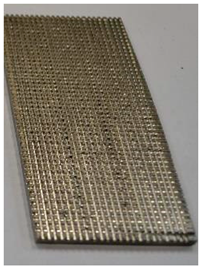
On the surface of the plates, the laser radiation created a macro-relief with cross dimensions of 1 × 1 mm and different heights and spacings based on
Table 4. The real samples are presented in
Table 5. Then, the samples were prepared for the casting process based on the procedure mentioned in
Section 3.
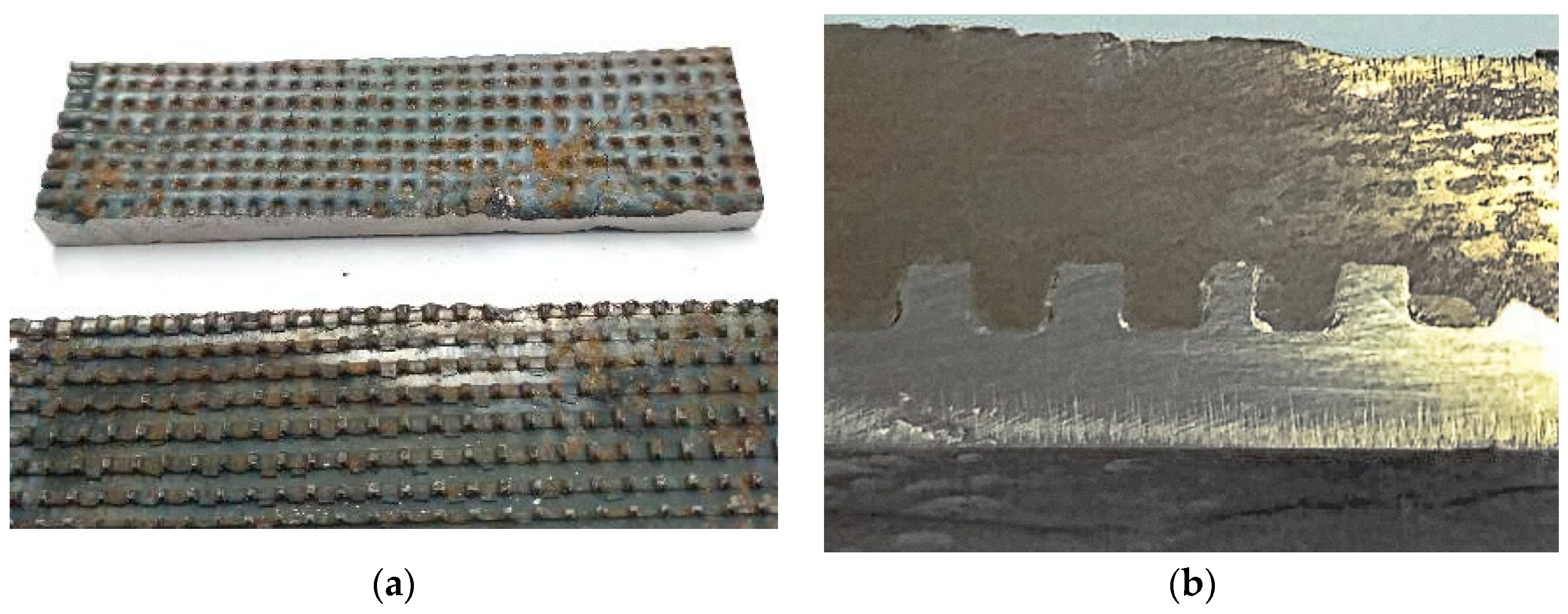
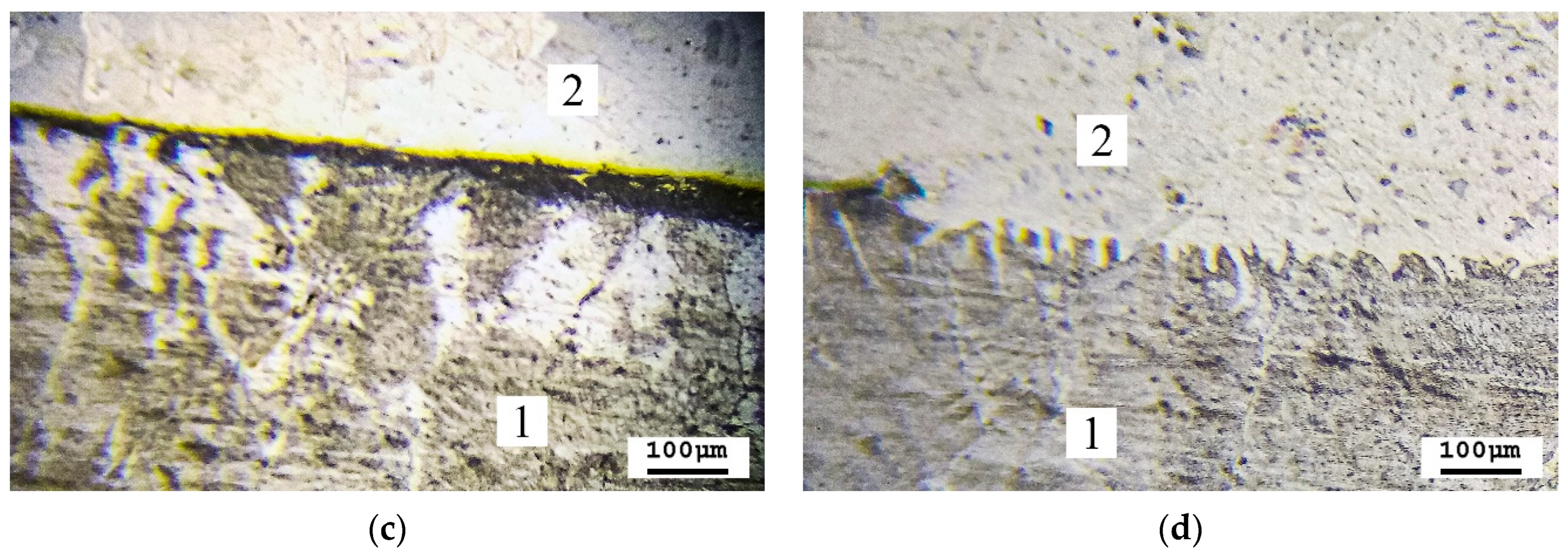
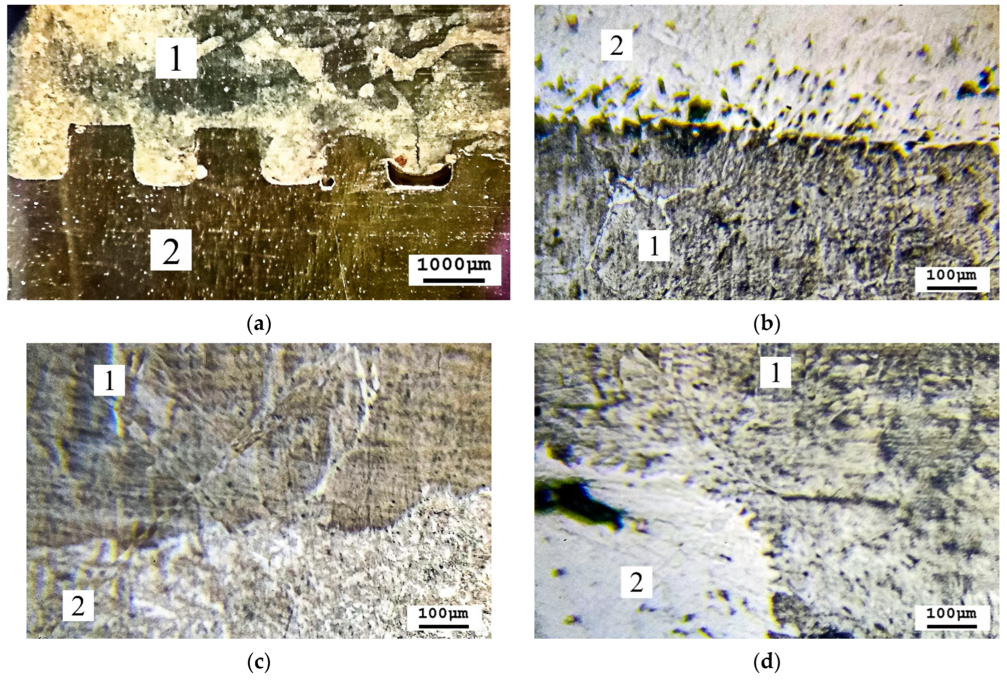
Following preliminary mechanical tests, it was found that some samples had delaminated and were excluded from further studies. Specifically, samples with dimensions of 1 × 0.5 h; 1 × 1.0 h; 1.5 × 1.0 h; 2 × 0.5 h, and 2 × 1.0 h—which constituted about 55% of the total number—had completely delaminated. Infiltration and encapsulation of the protrusions of the applied structure were observed (
Figure 3 and
Figure 4). Areas where S235JRG2 melt did not mix were those where the temperature was not sufficient for infiltration due to high heat dissipation in the area of interaction between the two environments.
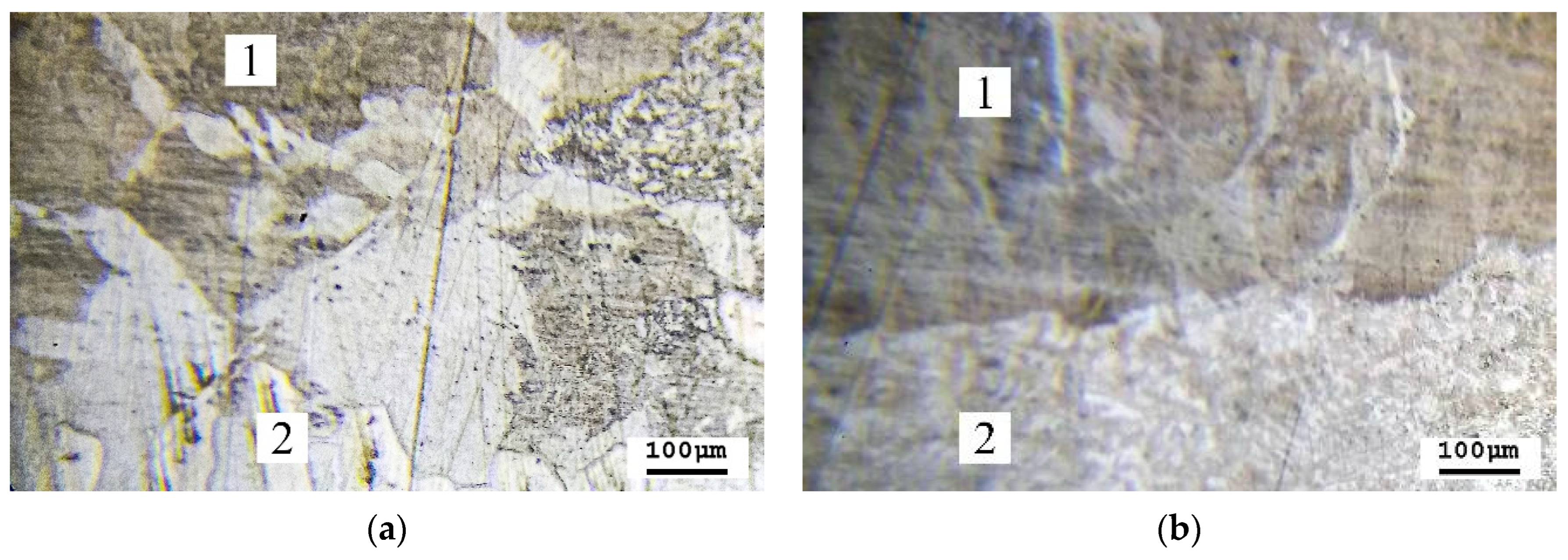
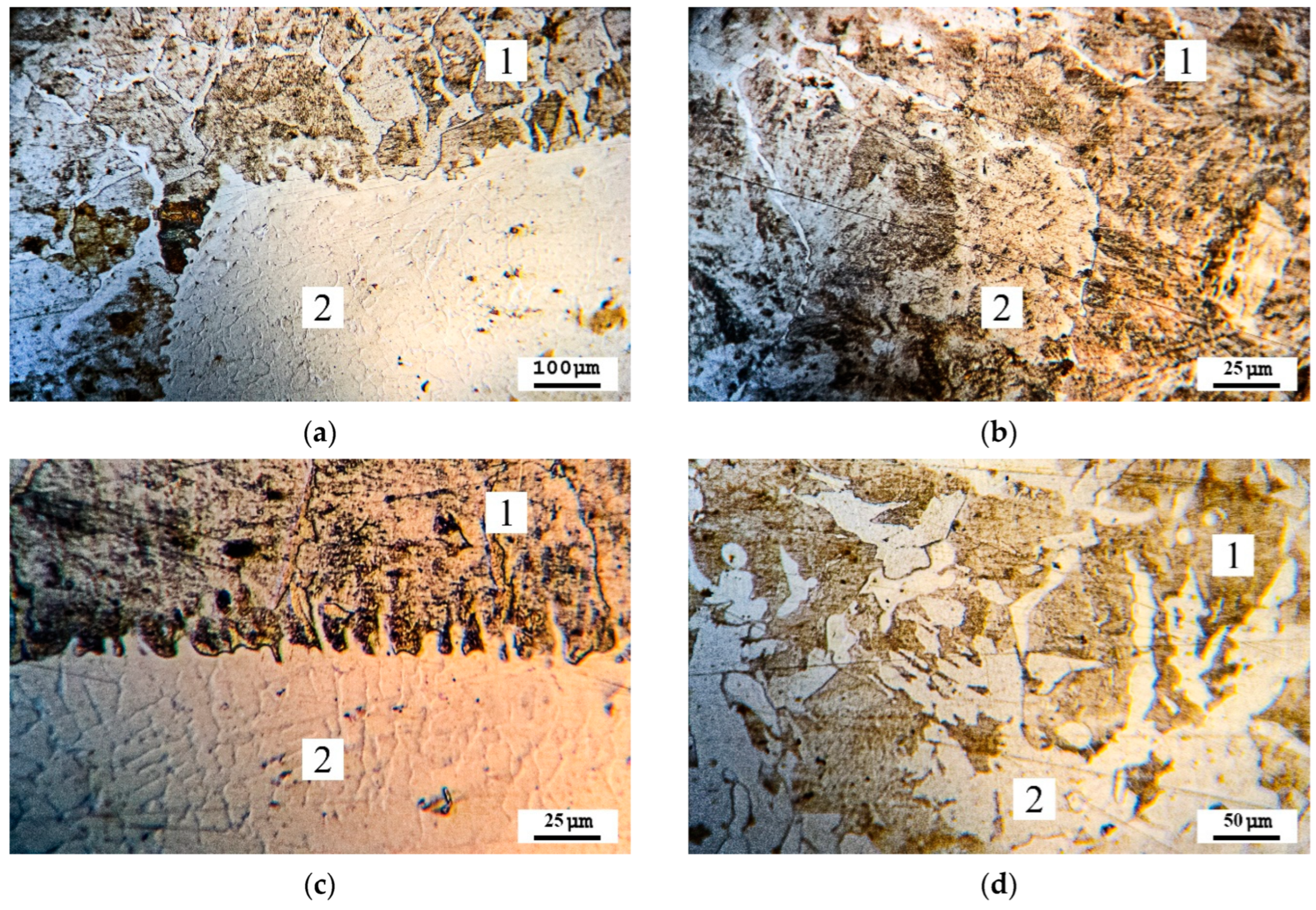
Microanalysis of samples 1 × 1.5 h, 1.5 × 1.5 h, and 2 × 1.5 h showed that the casting side had some mechanical bonding and that there were individual contact zones with metallurgical bonding. The ratio of the contact area to the total did not exceed 10–15% (
Figure 5).
Figure 6 presents the microstructures of the obtained bimetallic two-layer castings. During the microanalysis of sections from the 1.5 × 0.5 h sample, a stable formation was detected in the contact zone of the molten steel S235JRG2 with the nickel alloy UNS 6230. The protrusions had a height of 0.5 mm, and they were positioned at a 1.5 mm interval. The contact area’s ratio to zones where a metallurgical bond is observed (the boundary lacks a separation zone) exceeded 85% across the entire bonding boundary.
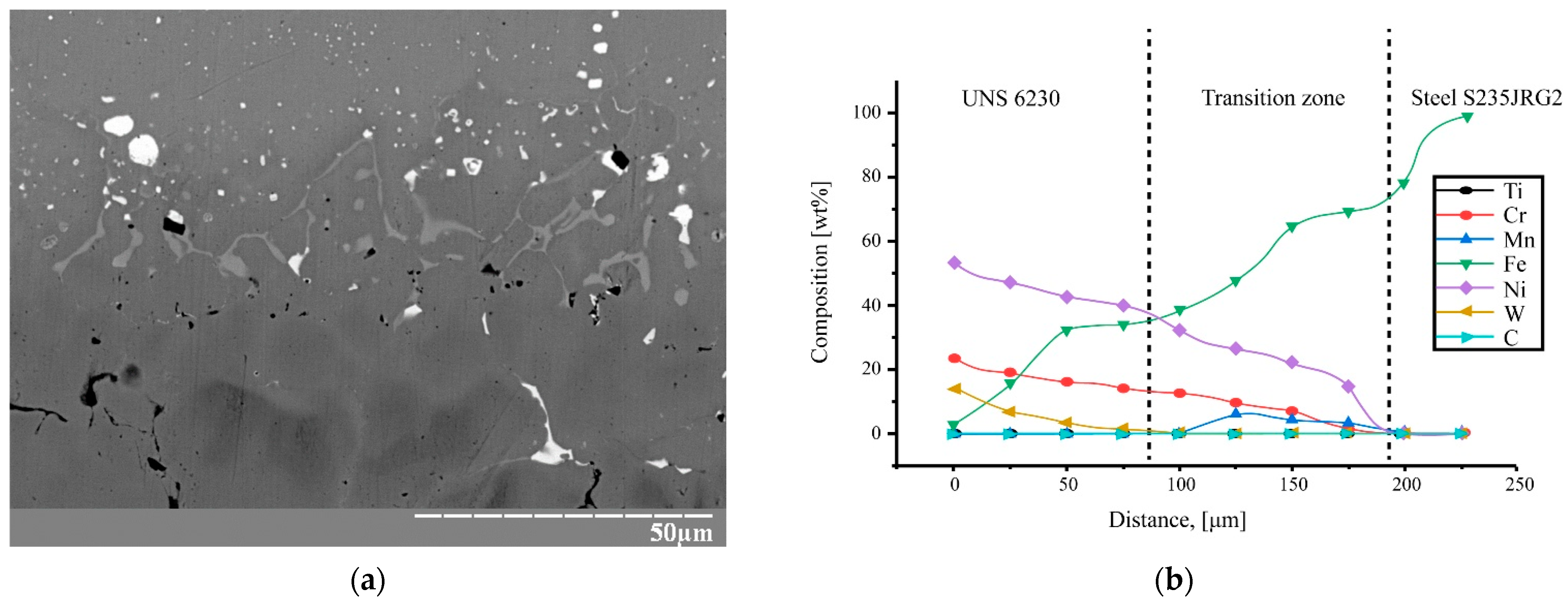
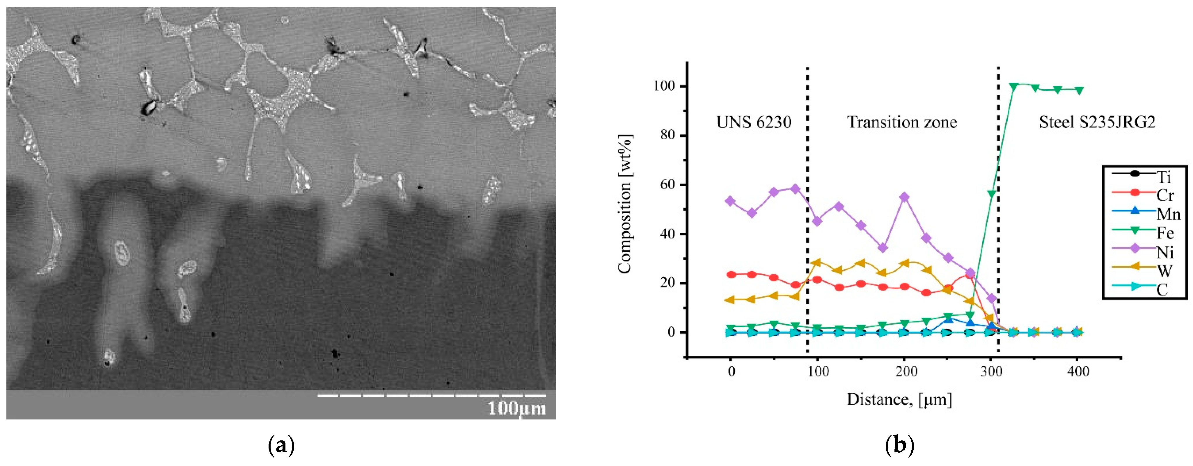
As a result of the diffusion of carbon and alloying elements such as Cr, Ni, and W, a transition zone was formed at the boundary between the carbon steel S235JRG2 and the plate made of the nickel alloy (UNS 6230). The width of this melting zone varied from 80 to 170 µm. The shape of the transition zone structurally differed from S235JRG2 and UNS 6230 which clearly indicates the diffusion process (
Figure 5).
Interlayer diffusion is the process in which atoms of one material move into another material across the interface. In the case of bimetals such as Ni, Cr, W, Fe, and C, this process affects the microstructure and mechanical properties of the final product.
The diffusion mechanisms in Ni, Cr, W, Fe, and C can be explained by processes in high entropy alloys, where each atom of the constituent elements has an equal probability of occupying a lattice site. Due to the heterogeneity of the atoms, the potential energy between the lattice sites varies. Fluctuations in the potential energy of interatomic bonds significantly affect the kinetics of diffusion and its activation energy [
34]. Nickel aids in the stabilization of austenite, while tungsten has a low diffusion capability. In the bimetal’s interfacial zone, carbides like tungsten carbide (WC) and Cr
3C
2, Fe
3C, WC, and Ni
3C do not form. This improves the properties of the transition layer, as these phases can act as potential stress concentrators under cyclic loading or fatigue, leading to cracks and defects during further operation. The absence of carbides is also confirmed by the microhardness measurements, which show a smooth variation and indicate the absence of points with increased microhardness [
35].
Phase formation processes for Ni-Cr-Fe and Fe-Ni are complex and depend on several thermodynamic and kinetic factors [
36]. Diffusion occurs through vacancies and interstitial positions in the crystal lattice and depends on temperature and concentration gradients [
37].
Based on the results of SEM microscopy (
Figure 7), it can be concluded that the protrusions on the functional component almost completely melted, resulting in the formation of a solution of the nickel alloy in the carbon steel. The boundary of separation is blurred and has a wavy shape, which is due to the geometry of the protrusions that were on the surface of the nickel alloy prior to interaction with the melt. On samples with protrusions that had a greater height (1 mm), the waviness of the melting zones has a larger amplitude, to some extent replicating the profiles of the protrusions. However, this sample had a low bonding area, not exceeding 20%, due to the insufficient temperature in the transition zone and high cooling rates.
For the 1.5 × 0.5 h sample, the ratio of the contact areas with zones where metallurgical bonding occurred was the highest, accounting for 97–98%; for 2 × 1.5 h it was 25–30%. In the microstructural images, two layers are clearly visible. The upper layer, whose microstructure is practically indiscernible when treated with standard reagents, belongs to the nickel alloy. This layer is adjacent to the ferrite–pearlite structure of the carbon steel S235JRG2.
Upon further magnification, clusters of white-colored grains of various sizes became visible at the boundary between these structures and in certain areas of them. These regions also resist etching poorly and have a higher content of Cr, Ni, and W.
In addition to optical metallography, structural studies were conducted using elemental chemical microanalysis with a scanning electron microscope equipped with a micro-X-ray spectroscopic attachment (
Figure 8 and
Figure 9;
Table 6 and
Table 7).
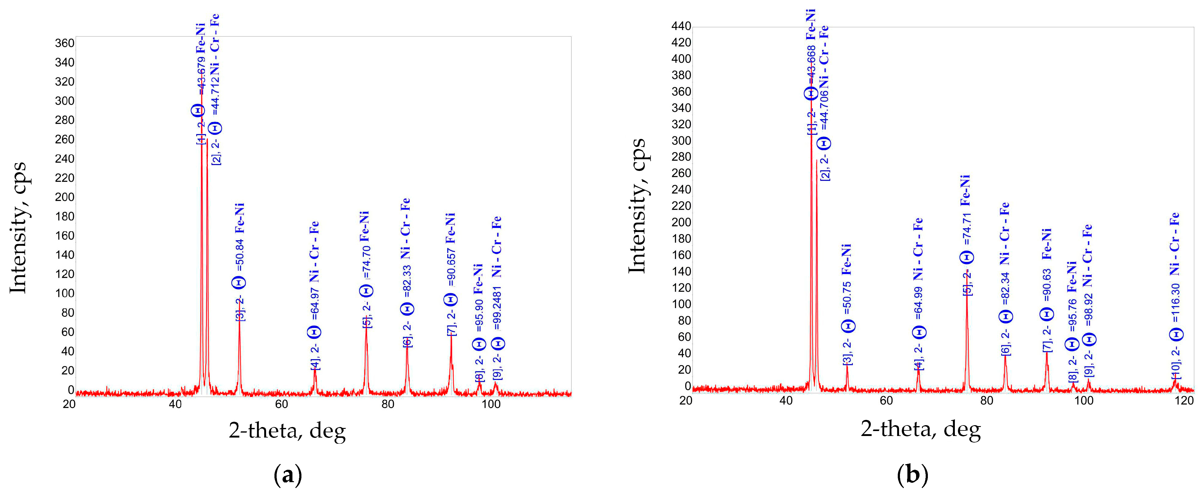
X-ray phase analysis diffractograms of the transition zone, taken from the area of the bimetal’s cross-section with a diameter of 6 mm, that were symmetrical and relative to the hypothetical line of connection, can be seen in
Figure 10. The sample’s transition layer had a macro-relief of 2 × 1.5 mm, and the bimetal parts were only fusing at a level of 20–30% per area. The content of the NiCr–Fe phase constitutes 89.1%, and the Fe 0.507 Ni 0.493 (tetrataenite) phase constitutes 10.9%.
In the bimetal transition layer with the 1.5 × 0.5 mm parameters, when the content of the Ni-Cr-Fe phase in the fused layer amounted to 86.4%, the boundary of the fusion area was larger and the structure was more uniform. This is also evidenced by the increased in the Fe 0.507–Ni 0.493 phase (tetrataenite) to 13.6%.
The sample with a larger macro-relief (2 × 1.5 mm) had a smaller phase composition of Fe 0.507–Ni 0.493 (tetrataenite) in the transition layer, and the main phase was Ni-Cr-Fe. For the sample with a smaller macro-relief (1.5 × 0.5 mm), the phase composition of the transition layer was larger, and an increase in the content of the Fe 0.507–Ni 0.493 (tetrataenite) phase was also observed—this could be due to a faster cooling rate in the first case, as the area of heat dissipation is larger under identical conditions of casting with the liquid base phase.
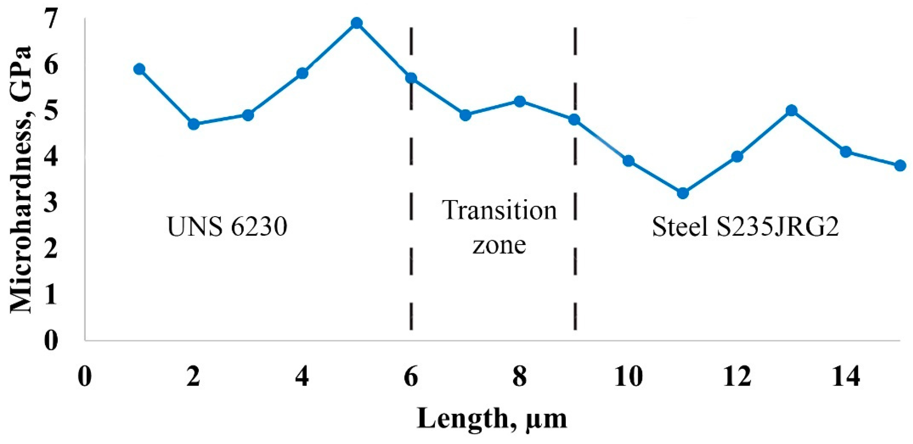
On the sections of bimetal samples, the functional component of which had a macro-relief of 1.5 × 0.5 mm, the distribution of the microhardness was determined in the direction perpendicular to the bonding zone from the surface to the carbon steel under a load of 50 g.
Figure 11 presents the results of the microhardness measurements, which show a sufficiently smooth decrease from 5 to 7 GPa in the nickel alloy to 4–5 GPa in the fusion zone and 3–4 GPa in the carbon steel.
Such a smooth decrease in microhardness in the fusion zone when transitioning from the nickel alloy to S235JRG2 indicates the distribution and mixing of the bimetal components, which affects the mechanical properties of the transition zone. Not only the magnitude of microhardness but also its distribution in depth indicate changes in microstructure and mechanical properties along the cross-section of the sample.
It was found that, with a macroscopic structure ratio and an increased interval to height at the same pouring temperature of 1600 °C (sample 2 × 1.5 h mm; sample 1.5 × 0.5 h), the solid phase in the melt leads to the formation of a more uniform microstructure, reducing the grain size and decreasing the number of defects in the material. This positively affects the mechanical properties, increasing the hardness and strength of the bimetal’s transition layer. The main focus was on achieving a transition layer where alloying elements diffuse from one component to another, forming a transition layer with mechanical properties that ensure a high-strength bond between the bimetal components and minimize the formation of defects and cracks during the subsequent operation of the products.
Overall, the transition layer is homogeneous and characterized by the presence of phases, which, during further operation, will prevent the concentration of internal stresses, which will positively affect the mechanical characteristics of the casting as a whole in the future.
The new technology, which combines pre-laser treatment with traditional casting methods, is highly efficient and will have broad applications across various industries as it achieves high levels of productivity, quality, and reliability. The developed technology enables the production of a variety of bimetallic combinations tailored to specific needs, significantly expanding its application.
The material exhibits improved mechanical properties. The regular macroroughness created by laser treatment on the surface during the casting process enhances the levels of adhesion between the layers (due to diffusion) and improves mechanical properties. This is particularly important for the oil, chemical, and heavy industries, where functional components are exposed to aggressive environments at high temperatures. As a result, parts can operate longer without significant defects, reducing maintenance costs and equipment downtime.
Enhanced Microstructure: Optimizing the ratio of the melt phase to the solid phase, as well as the pouring temperature, creates a more uniform and robust structure with a better distribution of alloying elements between the layers.
Microscopic studies revealed numerous formations near the fusion site. It was also noted that the obtained structure has a heterogeneous density of alloying elements, with their concentrations highest in the area of dissolution and diffusion in the transition zone. Furthermore, the chemical composition analysis showed that new phases had formed in the area under investigation.
Comparison with Existing Technologies:
Explosive Welding: Although it is known for its high productivity, explosive welding has low controllability and quality, especially in large areas. The new technology offers more precise process control, resulting in a higher product quality with equal or even greater productivity. Explosive welding generates high levels of noise and vibration, which require significant safety measures to be put in place. The new technology is safer and more environmentally friendly. Additionally, explosive welding can result in a less uniform microstructure and weaker bonds, particularly over large areas. The new technology addresses these issues, providing a more reliable and stable product.
Thermal Spraying: Thermal spraying methods often have a low adhesion strength, limiting their use under high loads. The new technology ensures stronger bonds between layers, increasing the durability and performance of the final product. Thermal spraying is not suitable for parts subjected to cyclic loads because of the risk of delamination.
Metallographic studies have established the conditions under which a metallurgical bond is formed between the bimetallic components, ensuring the high strength of their connection. It was proven that to achieve high strength of the bimetal components’ connection and an even distribution of this strength across the bonding plane, the height of the macro-protrusions and their pitch must have optimal dimensions.
