Article

Numerical and Experimental Study on Dummy Blade with Underplatform Damper

1
School of Mechanical Engineering, Shanghai Jiao Tong University, Shanghai 200240, China
2
Commerical Aircraft Engine Company Limited, Aero Engine (Group) Corporation of China, Shanghai 200241, China
3
School of Energy and Power Engineering, Beihang University, Beijing 100191, China
*
Author to whom correspondence should be addressed.
Machines 2024, 12(7), 461; https://doi.org/10.3390/machines12070461
Submission received: 22 May 2024 / Revised: 30 June 2024 / Accepted: 2 July 2024 / Published: 7 July 2024

Abstract

:
To confirm the variation in damping ratio offered by dry friction dampers against structural vibration stress, this study developed a blade vibration response test system for capturing damping characteristic curves through both frequency sweep excitation and damping-freevibration methods. The damping-free vibration method demonstrates high efficiency, allowing for the acquisition of a complete damping ratio characteristic curve in a single experiment. Experimental findings indicate that the two contact surfaces on the triangular prism damper produce distinct damping effects, closely aligning with the predicted damping characteristic curves. The peak damping ratio was found to be independent of the centrifugal load of the damper; dampers with varying contact areas produce approximately similar damping characteristics; and the damping effect shows a positive correlation with the root extension length.

1. Introduction

The rotor blades of aircraft engines and general gas turbines are subjected to alternating loads during operation, which frequently experience flow-induced vibrations that have implications for the fatigue life of the structure [1,2,3]. Reducing vibration stress in rotor blades is an issue in the design of aero-gas turbines. One efficacious strategy employed is the integration of dry friction damping mechanisms into blade designs [4,5,6,7,8]. Common dry friction damping structures include underplatform damper (UPD) [9], shroud [10], and frictional ring [11], etc. When vibration occurs in the blades, the damping devices convert vibrational energy into heat via frictional interaction between contacting surfaces [12].
Situated within the interstitial space beneath the blade platform, the UPD makes contact with the platforms of adjacent blades. In consideration of their distinctive structural features and design principles, UPDs adopt a variety of geometric profiles that play a pivotal role in determining their damping effectiveness. Ferhatoglu et al. [13] found that transitioning the cross-sectional profile of a wedge damper from an isosceles right triangle towards a flatter shape results in a marked diminishment in the amplitude of oscillatory responses. Denimal et al. [14] observed that when adjacent blades vibrate in phase, the conical dampers demonstrate superior vibration suppression over cylindrical dampers, with a more stable contact status compared to wedge dampers. Furthermore, the damping characteristics of a conical damper can be altered by adjusting the cone angle. To avoid this rolling phenomenon of asymmetric damper, Gastaldi et al. [15,16,17] prescribed a range of geometric parameters and design limitations. It is noteworthy that common wedge and cylindrical UPDs are susceptible to rolling motion, which compromises damping efficiency. Additionally, Panning et al. [18] innovatively amalgamated the beneficial aspects of wedge and cylindrical dampers in designing an asymmetric damper. Their research showed that during the vibrational process, the locus of the friction force on one of the interface surfaces shifts in accordance with the phase disparity between the adjacent blades.
Several researchers have employed model order reduction techniques to model bladed disks with UPDs. In such instances, the UPD can be treated as a rigid body; only the reduction of blade and disk is needed. Cigeroglu et al. [19] decomposed the displacement of the model into the linear combination of its normal modes. Salas et al. [20] used Craig–Bampton Cyclic, Craig–Bampton Multisubstructuring, and subset nominal mode to conduct the reduction of the order model (ROM) of the blade disk assembly. Mehrdad et al. [21] combined the Craig–Bampton Method with the Loaded Interface Method [22] to develop an ROM specifically for mistuned bladed disk structure. Gola et al. [23] modeled the UPD as a point mass moving in a platform, thereby enabling the calculation of its damping characteristic. Rani et al. [24] represented the blade with UPD using Bond Graph formalism, and subsequently analyzed the model through numerical integration techniques.
In addition to theoretical studies, researchers have carried out extensive experimental research on the vibration-damping capabilities of UPDs. Pesaresi et al. [25,26] introduced a pioneering experimental methodology for UPDs, in which a wedge-shaped UPD was tensioned upwards with steel wire to simulate centrifugal load. Laser displacement sensors were employed to measure the displacement of the blade tip. Their analysis delved into the blade’s reaction under varying excitation forces. When adjacent blades were vibrating in phase, the resonance frequency exhibited a significant shift with increasing force input, and the frequency response functions (FRFs) showed softening behavior and indicated a reduced damping effect. Their subsequent experiment used digital image correlation (DIC) and high-speed imaging techniques to observe the rotation of dampers during in-phase vibration.
Zhang et al. [27] executed vibration experiments using dampers of different cross-sectional geometries and inserted pressure-sensitive paper between the contact surfaces to monitor the contact state. They found that a smaller effective contact area results in a greater resonance response. Ferhatoglu et al. [28] designed an experimental setup incorporating two dampers and a blade, tensioned using steel wires to simulate centrifugal load. The system included four force sensors and a laser displacement sensor to measure the friction force on the contact surface and the displacement of the blade tip. They performed a series of repetitive experiments under similar conditions to gather distinct FRFs, aiming to explore the occurrence of multiple responses due to the non-uniqueness of friction forces. Using two previously suggested methodologies for the boundaries of FRFs, they compared these predictions with experimental outcomes [13,29]. Their experiment not only verified the accuracy of the method of predicting the response boundary but also confirmed that the uncertainty of dynamic response is attributed to the non-uniqueness of tangential forces.
It should be noted that all the previously discussed experimental configurations did not account for dynamic responses influenced by rotational effects such as stress stiffening and rotational softening. Hoffmann et al. [30] addressed this deficiency by designing a specialized rotating test rig. In their setup, blades were excited using permanent magnets situated underneath, and the resulting measurement data were transmitted from the rotating assembly to the stationary data-acquisition system through the use of slip rings. The test observed a 92% reduction in resonance amplitude, providing experimental evidence of the effectiveness of the dampers.
Building upon the foundational principles of dry friction energy dissipation theory, the research group associated with the author [31,32,33] previously developed a novel approach for computing the damping ratio characteristic curve of a blade with UPDs and a corresponding method for optimizing the damper mass using the damping ratio characteristic curve. Based on this theory, a non-rotating dummy blade damping characteristic testing system was designed. Through this experimental apparatus, the investigation conducted vibration response experiments on prototype blade samples featuring triangular prism-shaped UPDs, employing both the externally applied excitation method and the damping-free vibration testing methodology. This allowed for obtaining the critical damping ratio’s dependence on structural vibration stress, thereby substantiating the validity and applicability of the design and analytical methods. Furthermore, the study delved into the impact of several key structural parameters of UPDs, including inherent inertial loads, length of the shank, and contact areas on the damping ratio. Notably, the experimental scope was confined to examining the first bending mode of the blade.

2. Test Rig Description

2.1. Test Rig

This paper describes an experimental apparatus designed to investigate the dry friction damping characteristics of UPDs in non-rotating states. The design criteria primarily include the following requirements: (1) the experiment utilizes a triangular prism damper, enabling the separate examination of the damping effects on each contact surface; (2) it is capable of simulating the centrifugal force acting on the damper during engine operation in a non-rotating state; (3) the experiment aims to avoid introducing additional damping.
The experimental specimens were crafted in strict accordance with the aforementioned requirements. The blade specimen design is primarily inspired by turbo rotor blade designs, as illustrated in Figure 1. The complete blade specimen consists of the base plate, shank, platform, and blade body, which was excited to measure its vibrational response. The bladeless specimen excluded the blade body component, serving as a surrogate model that mimics the stiffness contributed by the platform while ensuring that it does not resonate when the complete blade is excited. To effectively simulate the first-order bending vibration of the actual blades, an installation angle of approximately 30° was set. During the experiment, the blade was affixed to the test bench with four bolts.
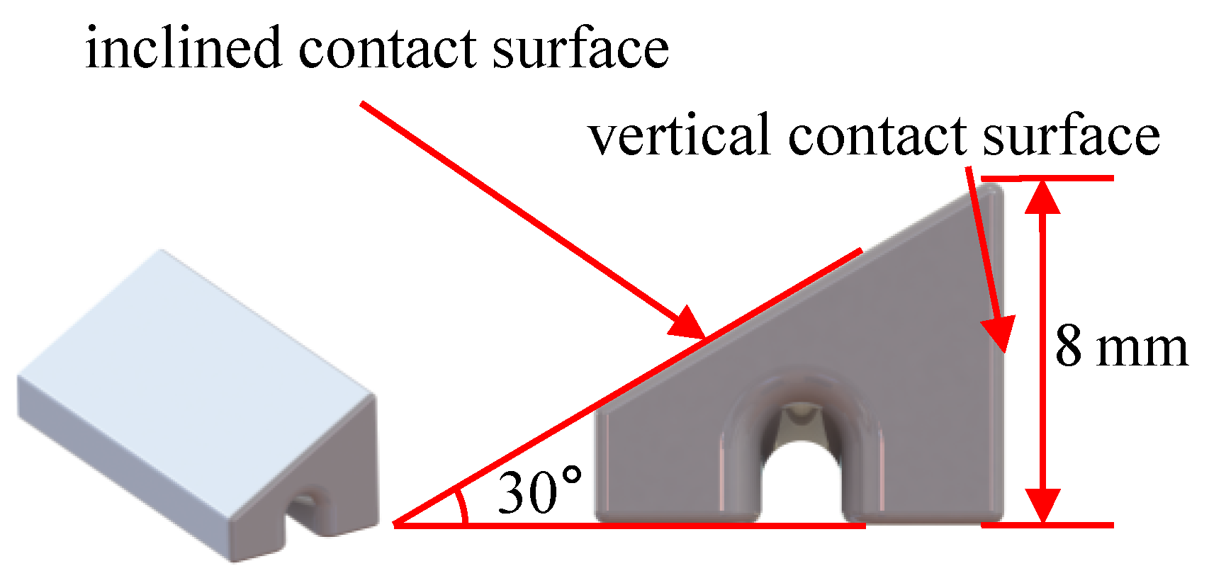
In the operational state of turbo rotor blades, the UPD is firmly pressed against the platform due to centrifugal force. For this experiment, it became essential to apply a force along the radial direction of the blade to accurately simulate the operational state of the damper specimen. The prism damper specimen, as designed in this study and depicted in Figure 2, exhibits stable operation and resistance to self-locking. It boasts two functional surfaces: one being a vertical contact surface, and the other referred to as the inclined contact surface. To simulate centrifugal force, slots have been integrated at the bottom of the damper to enable upward tension via steel wires.
Both the blade specimens and UPDs are fabricated from 45 # steel, a material frequently employed in industrial settings. The material properties of it are depicted in Table 1.
It should be emphasized that the UPD belongs to the category of dry friction damping structures. During rotation, the contact normal pressure is mainly derived from centrifugal force, necessitating additional loading in the experiment to mimic the influence of centrifugal force on the UPD. Under non-rotational conditions, the contact normal pressure can be calculated for the analysis of damping characteristics. Thus, in the validation experiment of dry friction damping, the rotation status of the blade does not alter the fundamental nature of the problem.
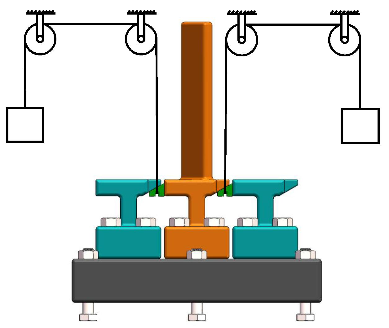
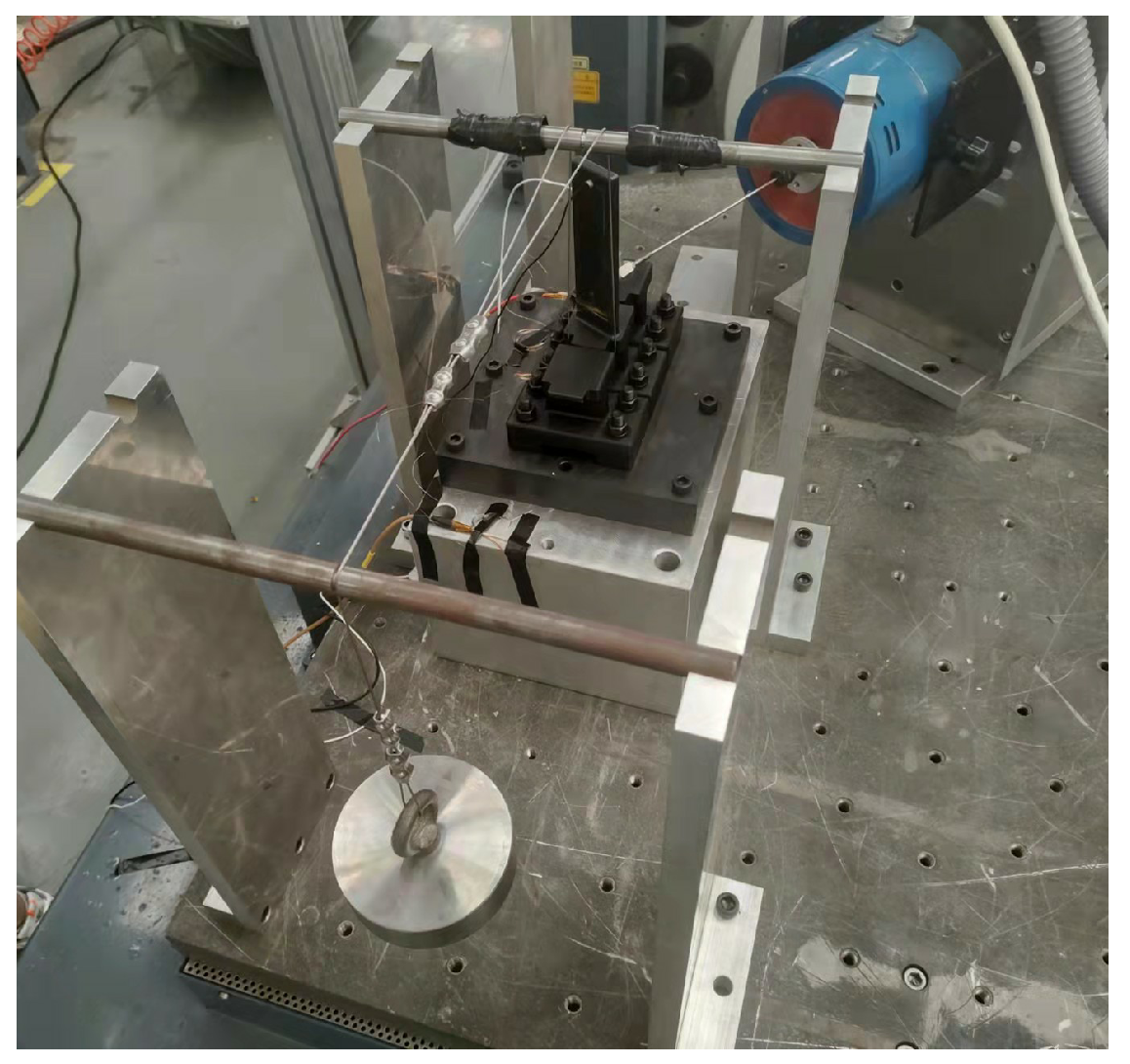
Figure 3 depicts a schematic diagram that shows the relative positioning of the blade and the damper during the experiment, which includes a complete blade specimen, two bladeless specimens, and two dampers. The experimental setup is installed as depicted in Figure 4. One end of a steel wire is threaded through the groove at the bottom of the UPD, securing the damper under the platform, whereas the other end suspended a weight to exert upward tension on the damper, simulating centrifugal loads during operation.
Adjusting the number of weights allows for the simulation of various centrifugal loads. We suppose that the contact surface of the UPDs and the complete blade specimen provides damping for it. The contact between UPDs and bladeless specimens are stuck. Installing a damper on the left side of the blade specimen enables the examination of the vertical contact surface’s damping characteristics, whereas placement on the opposite side facilitates the investigation of the inclined contact surface’s damping characteristics. This arrangement permits the independent analysis of each contact surface’s damping characteristics during the experiment.
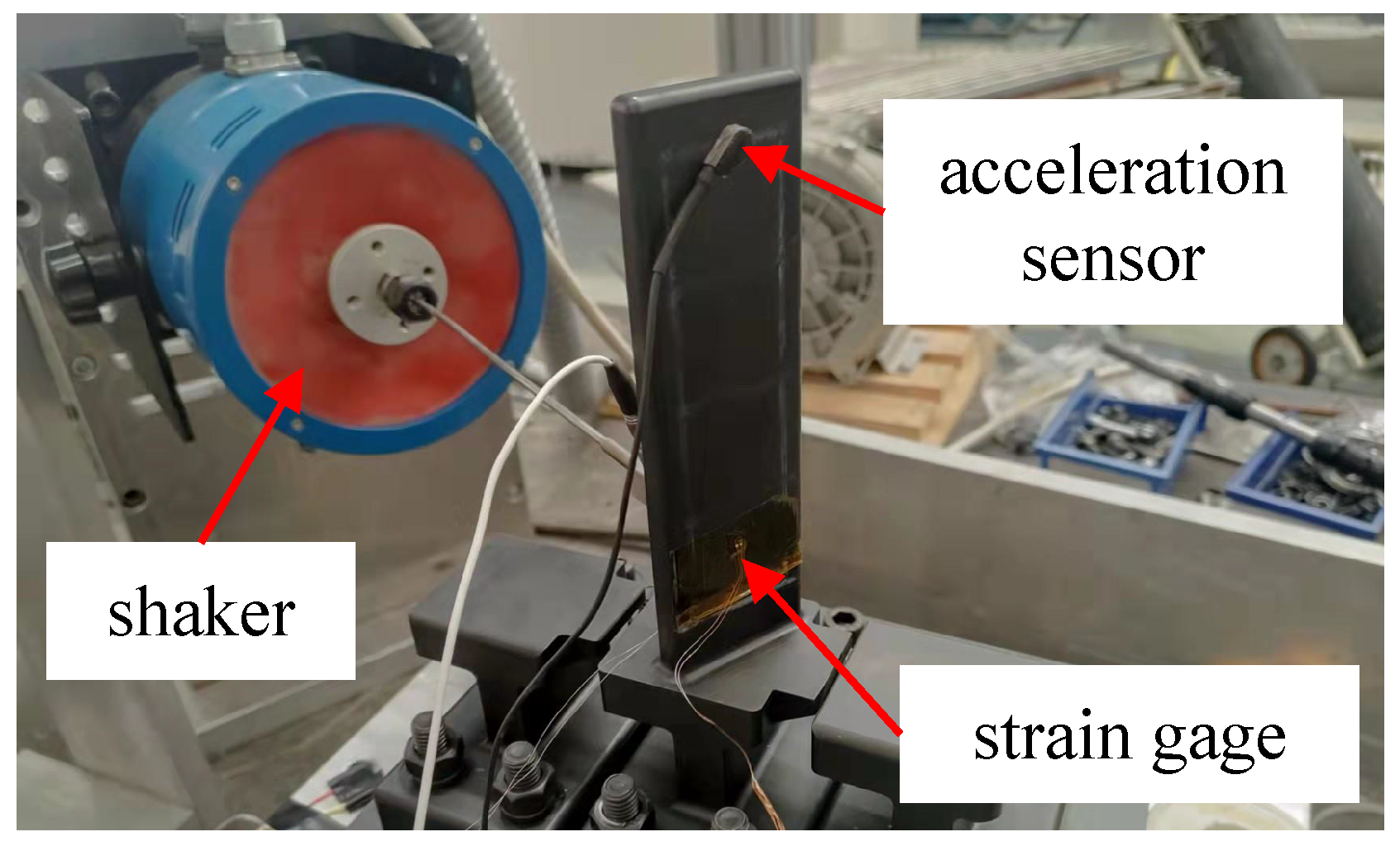
Figure 5 shows the experimental rig for the blade specimen. A shaker was employed to apply force to the blade specimen with controlled amplitude and frequency. To measure the stress of the blade, a strain gage was positioned at its root. Additionally, an acceleration sensor was affixed at the tip of the blade, serving as a means to monitor the acceleration responses.
For a structure with a strong nonlinear effect, some algorithms need to be used to calculate the displacement under certain excitation [34,35]. In this article, typical FRFs are shown in Section 4.2 , showing that the nonlinear effect of the damper is not obvious. So we assume that the test rig is a linear system with nonlinear damping. Such an assumption is used for the “logarithmic decrement method” in Section 2.2.2. In Section 3.1, we consider that the mode remains constant, which is based on this assumption as well.

2.2. Experimental Principles

2.2.1. Exciter Excitation

A sinusoidal vibration excitation at a specific level is applied to induce resonance within a single test specimen at its natural frequency. When the blade undergoes small deformations, the blade exhibits vibration behavior consistent with a linear combination of modes. It was assumed that the ratio of vibrational stresses to displacement responses remains constant (the linear mode does not change) under different amplitudes. With a clearly defined center position for the strain gauges and specified testing directions, the vibration strain response data gathered from any point on the blade specimen’s surface should, in theory, enable the estimation of actual vibration strain responses at various parts of the blade specimen.
Sweeping frequency sinusoidal excitation around the natural frequency was performed on the test rig to capture the FRFs. This procedure assists in identifying the resonance frequency of the blade specimens equipped with damping reduction structures. The resonance stress of the blade specimens at the identified resonance frequency was measured. The damping ratio was calculated by applying the half-power bandwidth method on FRFs. The relationship between the damping ratio and resonance stress were plotted, which is known as the damping ratio characteristic curve.

2.2.2. Damping-Free Vibration

This section concisely introduces the method of deriving damping characteristic curves via damping-free vibration tests. In the context of a damped single degree of freedom system, the general solution for the damping-free vibration response can be expressed as follows:
X ( t ) = A e ζ ω n t sin 1 ζ 2 ω n t + φ 0
where A is the amplitude, ζ is the damping ratio, ω n is the natural frequency of undamped structure, and φ 0 is the initial phase. The curve expressing the peak points of the damping-free vibration response can be represented as
x = A e ζ ω n t
The exponential function component in this expression causes the amplitude of the vibrational system to decrease with time. The system exhibits amplitude-diminishing oscillations. The rate of amplitude decay is quantified by the ratio of amplitudes of successive motion cycles.
The relationship between the absolute values of adjacent peak points (crest or trough values) and the damping ratio is
A k A k + 1 = A e ζ ω n t k A e ζ ω n t k + 1 = e ζ ω n 1 2 T = e ζ π 1 ζ 2 = φ
where A represents the amplitude of acceleration of stress. The proportionality constant in the equation represents the attenuation rate, where φ signifies that the amplitude of damped vibrations decreases geometrically. It is commonly employed to indicate the rate of decrease in amplitude. Introducing the natural logarithm of the attenuation rate can facilitate a more convenient calculation of the damping ratio, as follows:
δ = ln φ = ζ π 1 ζ 2
In the expression, δ is denoted as the logarithmic decrement. It can be utilized to calculate the damping ratio ζ .
ζ = δ π 2 + δ 2
There exists the following mathematical relationship between δ and lg φ :
lg φ = ln φ ln 10 = ln φ lg e = 0.4343 δ
Ultimately, an expression for the damping ratio can be derived, as follows:
ζ = lg φ 1.862 + ( lg φ ) 2
At this juncture, following the acquisition of the time-domain curve of blade vibration, the damping ratio can be determined based on the ratio of adjacent peak points. Simultaneously, through the amplitude of the strain gage measurements, the vibrational stress at the measurement point can be determined. This enabled the establishment of a correlation between the damping ratio and vibrational stress, ultimately resulting in the damping characteristic curve.

2.3. Experimental Method

2.3.1. Modal Testing

We fixed a blade specimen to the test bench and utilized the hammer impact method to determine the specimen’s natural modal frequencies, mode shapes, and modal damping ratios. Multi-point excitation and single-point measurement techniques were employed to assess the modal shapes of the blades. Subsequently, the UPD specimen was mounted. The impact of UPD on the first mode was evaluated through modal testing.

2.3.2. Shaker Excitation

The experiment rig for shaker excitation is detailed in Section 2.1. A frequency sweep near the resonance frequency of the blade specimen was conducted to obtain the FRFs. The half-power bandwidth method was employed to calculate the damping ratio and assess the resonance stress at the resonance frequency. Subsequently, the amplitude of the exciting force was adjusted to determine the structural damping ratio and vibration stress under different excitation conditions.
UPDs were installed on either the vertical contact surface or the inclined contact surface of the blade specimen. Subsequently, the UPDs were loaded by a range of inertial loads, allowing us to probe the influence of inertial loads on the damping characteristics.

2.3.3. Damping-Free Vibration

The damping-free vibration method was employed to derive the damping ratio characteristic curve. We attached an easily shearable thin wire to the blade that was approximately 15 mm away from the blade tip. The opposite end of the wire was suspended outside the test bench, suspending a weight. This configuration intentionally introduced an initial deflection in the blade. To minimize any disturbances caused by the weight impacting the ground after its descent, a soft sponge pad was placed beneath it. The strain gage and acceleration sensor were connected to a dynamic signal test and analysis system to record the vibration response of the blade. When the wire was cut, the blade would undergo a damping-free vibration. Through the recorded time-domain signal of the sensor, the damping ratio can be calculated through the method stated in Section 2.2.2. The process of this experiment is summarized in Figure 6.

3. Numerical Simulation Methods and Results

3.1. Computational Background

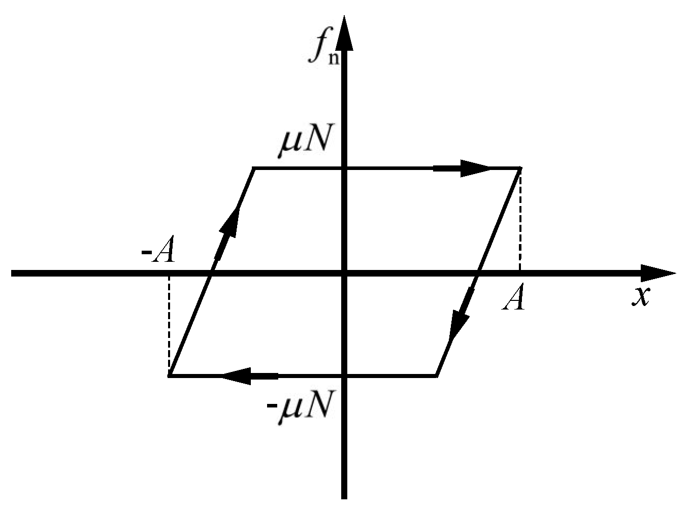
To enhance the analysis of vibrations, transforming the physical model of friction into a mathematical representation is essential. This involves simplifying the characteristics of relative motion between contact surfaces. By conceptualizing the contact surface as a single point exhibiting linear relative motion, a one-dimensional macro-sliding friction model becomes applicable for illustrating the contact behavior. This approach is depicted in Figure 7, showcasing the hysteresis curve of the friction force versus displacement. In this model, once sliding initiates, the magnitude of the friction force stabilizes and remains constant. The mathematical expression for this behavior is presented as follows [31]:
f n = μ N + k t ( x A ) , 0 θ < β μ N , β θ < π μ N + k t ( x + A ) , π θ < β + π μ N , β + π θ < 2 π
β = arccos ( 1 2 A 0 / A )
A 0 = μ N / k t
where μ is the coefficient of friction, N is the normal pressure at the contact surface, and k t is the tangential contact stiffness of the contact surface.
When the hysteresis curve depicting the variation of frictional force is acquired, integrating this curve provides the work performed by the frictional force over one cycle. This work represents the energy dissipated due to friction. Specifically, when the amplitude of relative displacement surpasses the threshold of critical displacement, the area enclosed by the hysteresis loop, which quantifies the energy dissipation, is calculated by the following formula:
W f = f n d x = 4 μ N ( A A 0 )
Once the energy dissipated by friction within one vibration cycle is determined, the damping ratio can be obtained by calculating the ratio of the frictional energy dissipation to the maximum kinetic energy of vibration. Assuming that the excitation force acting on the system follows a harmonic pattern, the vibrational displacement can be expressed as
x = A cos ( ω d t ) = A cos 1 ζ 2 ω n t
where ω d is the vibrational angular frequency, ζ is the damping ratio, and ω n is the natural frequency. The energy dissipated by friction is equal to the work conducted by the damping force within one cycle, specifically
W f = c π ω d A 2
where c is the damping coefficient. The maximum kinetic energy can be expressed as
W max = m ω d 2 A 2 2
where m is the mass of the blade. The ratio of the energy dissipated by friction to the maximum kinetic energy can be represented as
W f W max = 4 π c 2 m ω d 4 π ζ
It should be noticed that this equation only suits the condition that the damping ratio is low, so that ω d ω n . A method based on the circle-fit technique is suitable for a more general condition; the reader can reference [36] for detail. Therefore, with the determined values of the energy dissipated by friction and the maximum kinetic energy, the damping ratio can be approximated as
ζ = 1 4 π W f W max
which is acceptable for the first mode since the overall damping effect is rather low.
Considering that stress is commonly used as an evaluation criterion in high cycle fatigue (HCF), the relationship between damping ratio and vibrational stress needs to be obtained. Through modal analysis, the maximum stress σ ref , relative displacement at contact interfaces x ref , and modal kinetic energy of vibration W ref were obtained. This leads to the characterization of the damping ratio as a function of vibrational stress, known as the damping ratio characteristic curve. As the structure was vibrating in one mode, the ratio of vibrational stress to vibrational displacement remained constant. The actual vibrational stress, vibrational displacement, and vibrational kinetic energy are denoted as σ v , x v , and W v , respectively. The following relationship can be derived:
σ v σ ref = x v x ref = W v W ref

3.2. Results of Simulation

Modal analysis was conducted on the model of the blade specimen shown in Figure 1a using ANSYS. Fixed constraints were imposed on the nodes at bolt holes. The total displacement of the first-order bending mode is depicted in Figure 8.
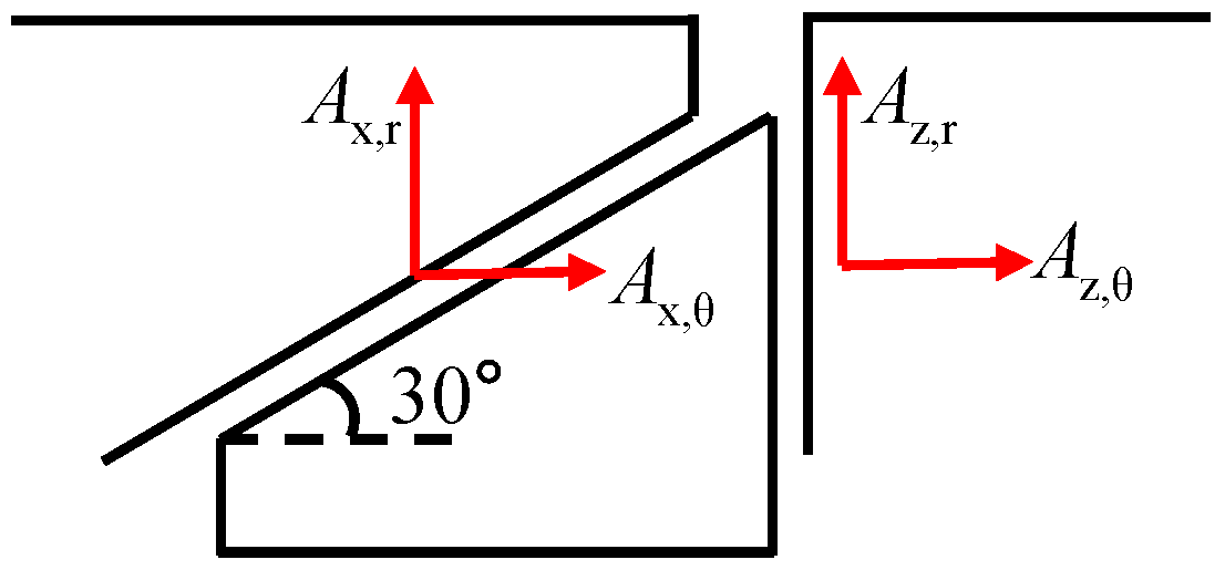
Based on the results of the modal analysis, the parameters required for analyzing the damping characteristics of UPD are provided in Table 2. The directions of the displacement of platforms are defined as Figure 9. We extract the mean radial and tangential modal displacement of each node situated at the two contact surfaces. The point on the blade body where the stress reaches its peak magnitude was selected. Since directly measuring the friction coefficient and tangential contact stiffness of the contact surfaces was challenging, the values provided in the table are estimated based on existing literature pertaining to experimental studies on other UPD vibration reduction devices. During the experimental process, the tangential contact stiffness and friction coefficient of the UPD were adjusted based on the experimental data obtained.
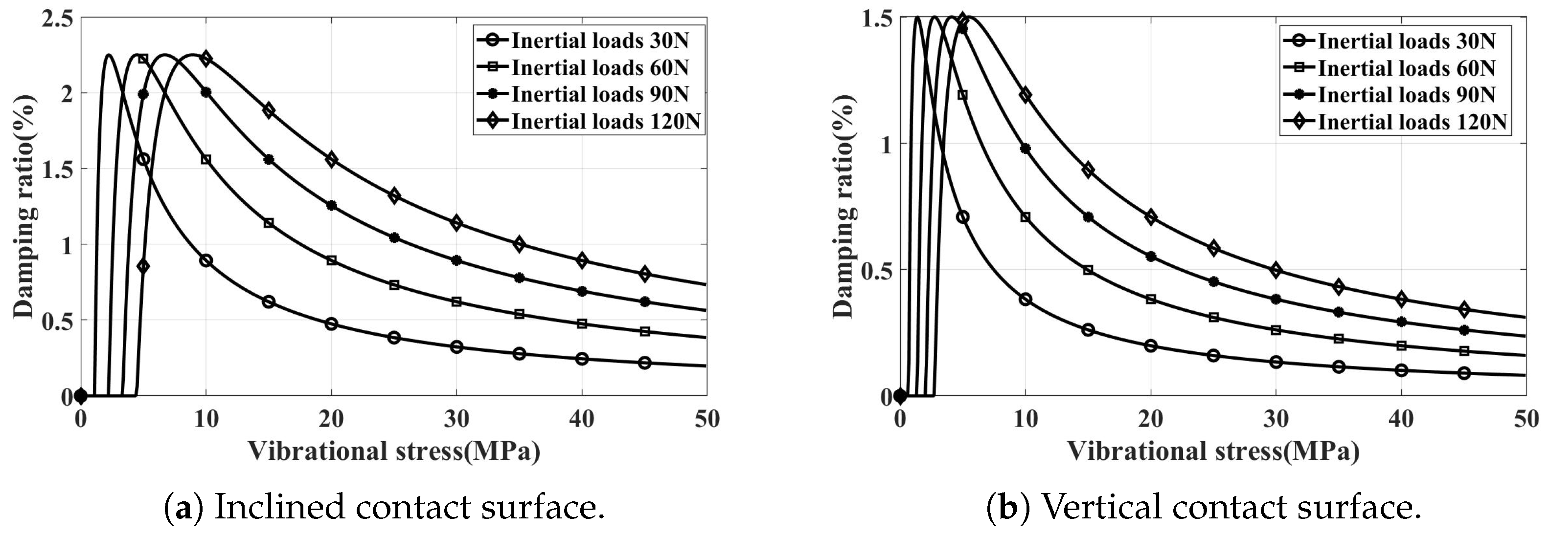
By employing the methods outlined in Section 3.1, we separately predict the damping characteristics under different inertial loads for both inclined and vertical contacted damper installations. The normal pressure on the contact surface, corresponding to various inertial loads, is shown in Table 3. The resulting damping characteristic curves are shown in Figure 10. It is evident that altering the inertial load merely scales the damping characteristic curve along the abscissa, with the peak damping ratio remaining constant.

4. Test Results

4.1. Modal Testing

Modal experimentation was conducted on blade specimens featuring various damper configurations and inertial loads. This involved striking the structure at various measurement points with a force hammer, capturing response signals at accelerometer positions, and analyzing the frequency response functions between different locations. The experiment primarily focused on the first bending mode, determining the first natural frequency of the blade by averaging multiple measurements. The experimental results are summarized in Table 4. A comparison between the experimental results and modal frequency calculations reveals consistency between simulation and experimentation. It was noted that the installation of underneath dampers resulted in a slight increase in the first modal frequency compared to the one without dampers, with minimal impact from varying simulated inertial loads.

4.2. Sweep Frequency Vibration Test

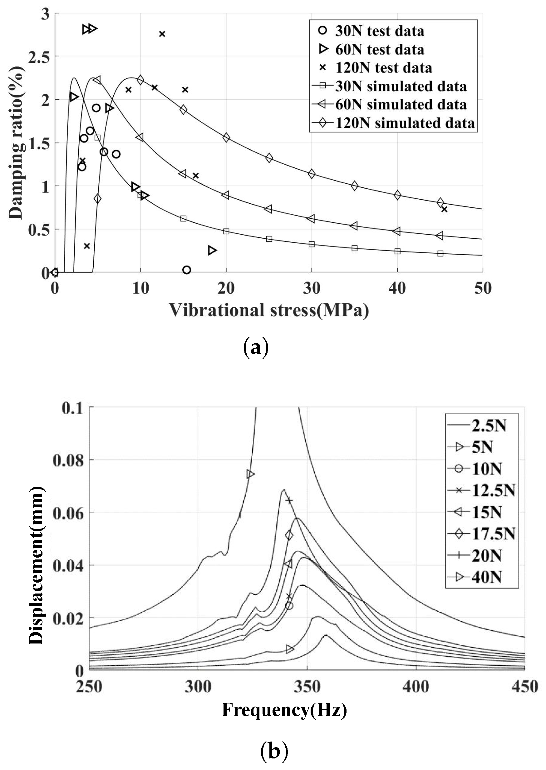
The UPD was installed on inclined contact surfaces with different centrifugal loads. The experimental and simulation results of the damping ratio characteristic curve are summarized in Figure 11.
Upon increasing the centrifugal force increased from 30 N to 60 N, an increase in the peak damping ratio was observed. However, upon further increasing the centrifugal force from 60 N to 120 N, no appreciable change in the damping ratio was detected. This phenomenon can be attributed to the fact that, at relatively low levels of normal contact force, changes in normal contact force cause alterations in the tangential contact stiffness. Consequently, this sensitivity leads to the actual tangential contact stiffness being lower than the predicted value when considering a centrifugal load of 30 N. The difference in contact stiffness caused a rightward bias in the damping curve relative to the predicted value. As the centrifugal load increases to a certain level, variations in tangential contact stiffness become less pronounced. With the increase of centrifugal loads, the critical vibration stress increases, while the peak damping ratio remains relatively constant, effectively reflecting this pattern in the simulation results.
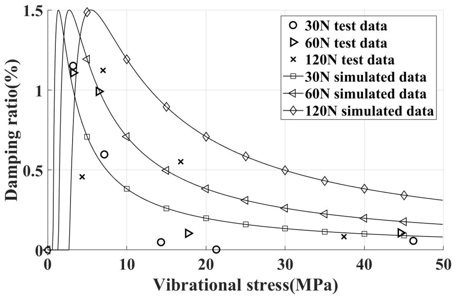
The experimental and simulation values for different centrifugal loads on vertical contact surfaces are summarized in Figure 12, showing that the peak dry friction damping ratio is around 1.5%. Overall, adding dampers significantly enhances the damping effect, achieving the goal of reducing vibration stress. Moreover, as the simulated centrifugal load changes, only the critical vibration stress varies, with the peak damping ratio remaining approximately constant. This consistency aligns with the damping characteristics revealed by simulation analysis.
It should be noticed that the experimental results have an obvious difference from the simulation results, which may be caused by the following results:
  • The inaccuracy of contact stiffness, especially for the experiments with an exciting force of 30 N.
  • Our simulation method only considers the tangential displacement of one direction, and the displacement in the other direction can increase the relative displacement of the UPD and blade, which can make the UPD provide more damping.
  • Only the damping of the contact surface of the complete blade specimen and UPD is considered in the simulation results; however, the contact surface of the bladeless specimen and UPD may provide damping as well, which may cause the maximum experimental damping ratio of the incline contact surface to be higher than the simulation results.

4.3. Free Vibration Test

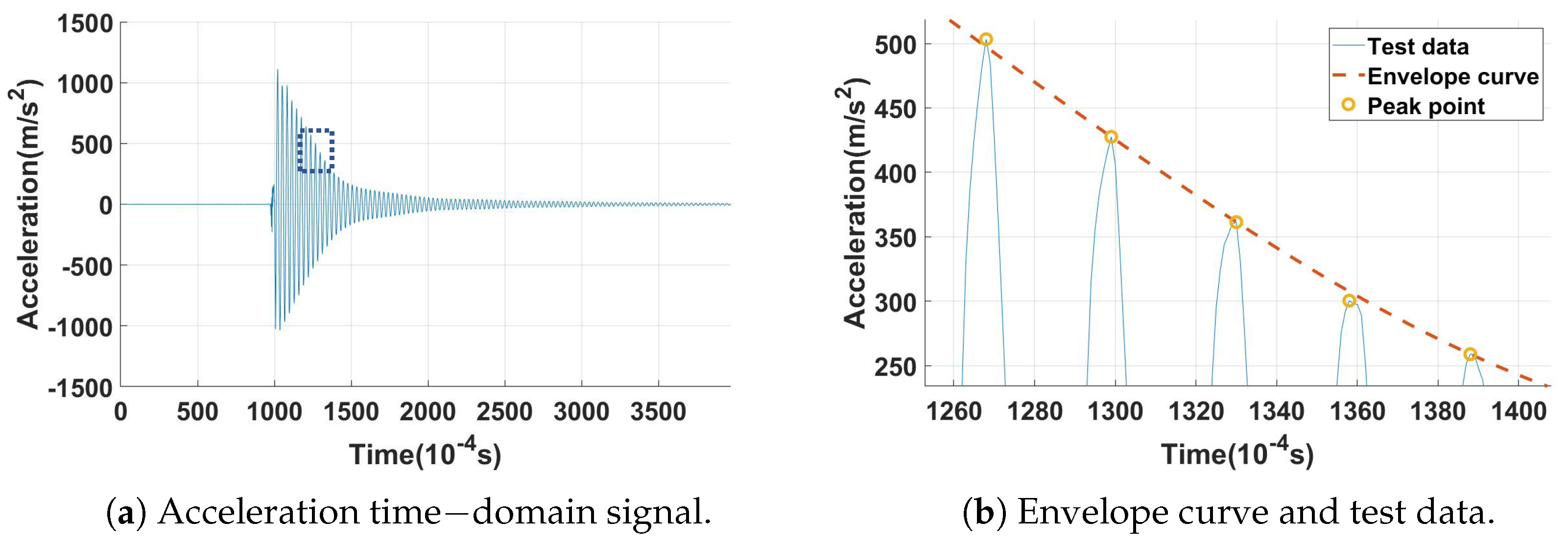
For the damping-free vibration test with 120 N centrifugal load, with a damper installed on the inclined contact surface, the acceleration sensor measurements pertaining to the first-order bending mode of the damping-free vibration are shown in Figure 13a. Upon the release of the applied load, the amplitude of the blade specimen diminished due to the combined effects of material damping and the damper.
Noting that during the process of calculating the damping ratio from the acceleration or strain time-domain curves, the peak data points may not perfectly align with the exponential decay function (Equation (2)), due to limitations imposed by the sampling frequency of the sensing equipment. To mitigate this potential source of error, the envelope curve of the time-domain response was plotted. A zoomed-in view is shown in Figure 13b. These circled peaks serve as the response points for subsequent damping ratio computations.
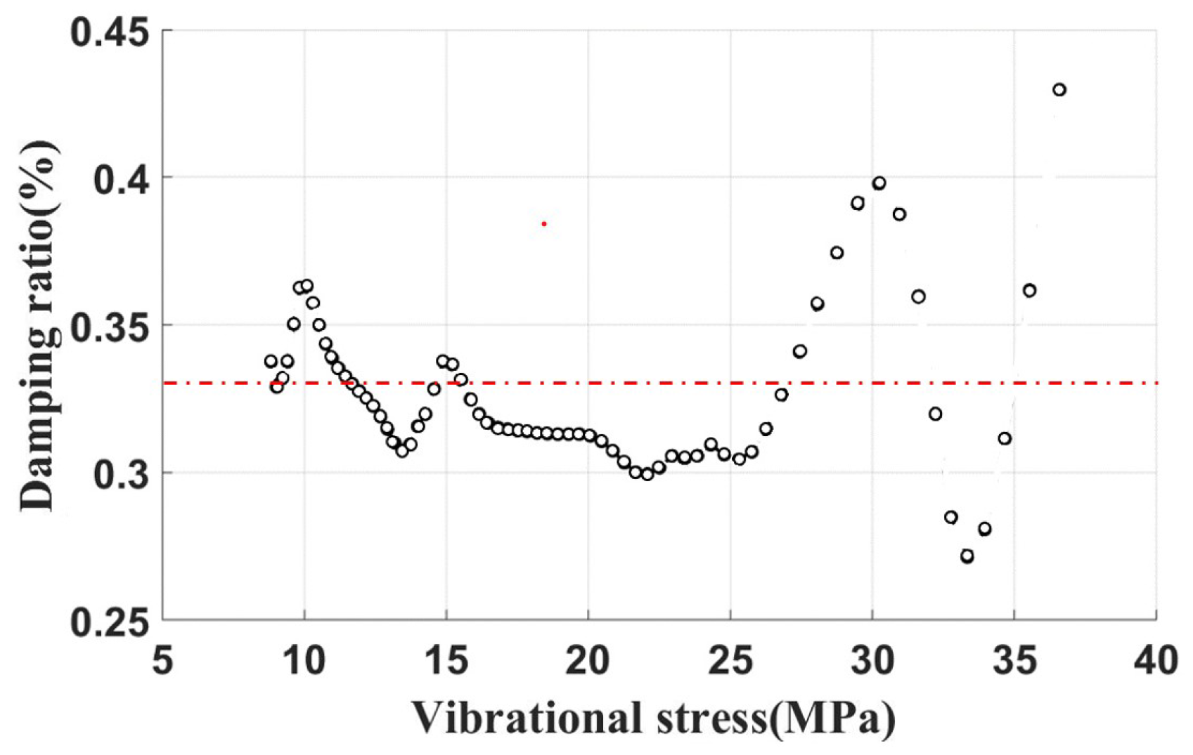
Damping-free vibration tests on the blades without dampers were conducted. An acceleration time-domain signal was acquired. The damping ratio is shown in Figure 14. The average value of the damping ratio is about 0.33% , a value demarcated by a dashed line superimposed on the plot. Therefore, such a damping ratio is attributed to the structural damping ratio of the blade. By subtracting this damping ratio (0.33%) from the experimental data, one can quantitatively isolate and ascertain the damping effect imparted by the UPDs.
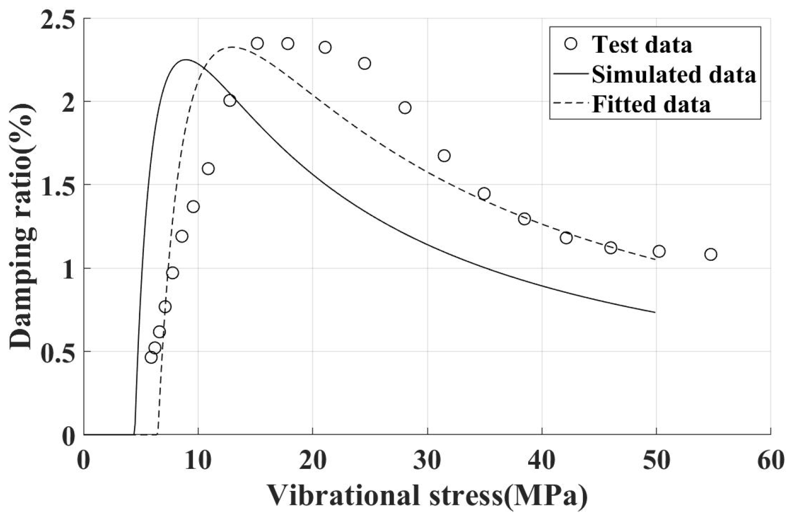
Owing to the complexity of directly measuring physical parameters of UPD, such as tangential stiffness and friction coefficient, parameters that exert a significant influence on the damping ratio, experimental estimates for these parameters were obtained through a process of curve fitting and inversion. The objective of this approach is to derive a reliable damping ratio characteristic curve for the damper. For example, applying a 120 N centrifugal load with the damper installed on an incline contact surface, the fitted damping ratio characteristic curve is shown in Figure 15. The experimental damping ratio characteristic curve of the damper aligns well with the simulation results.
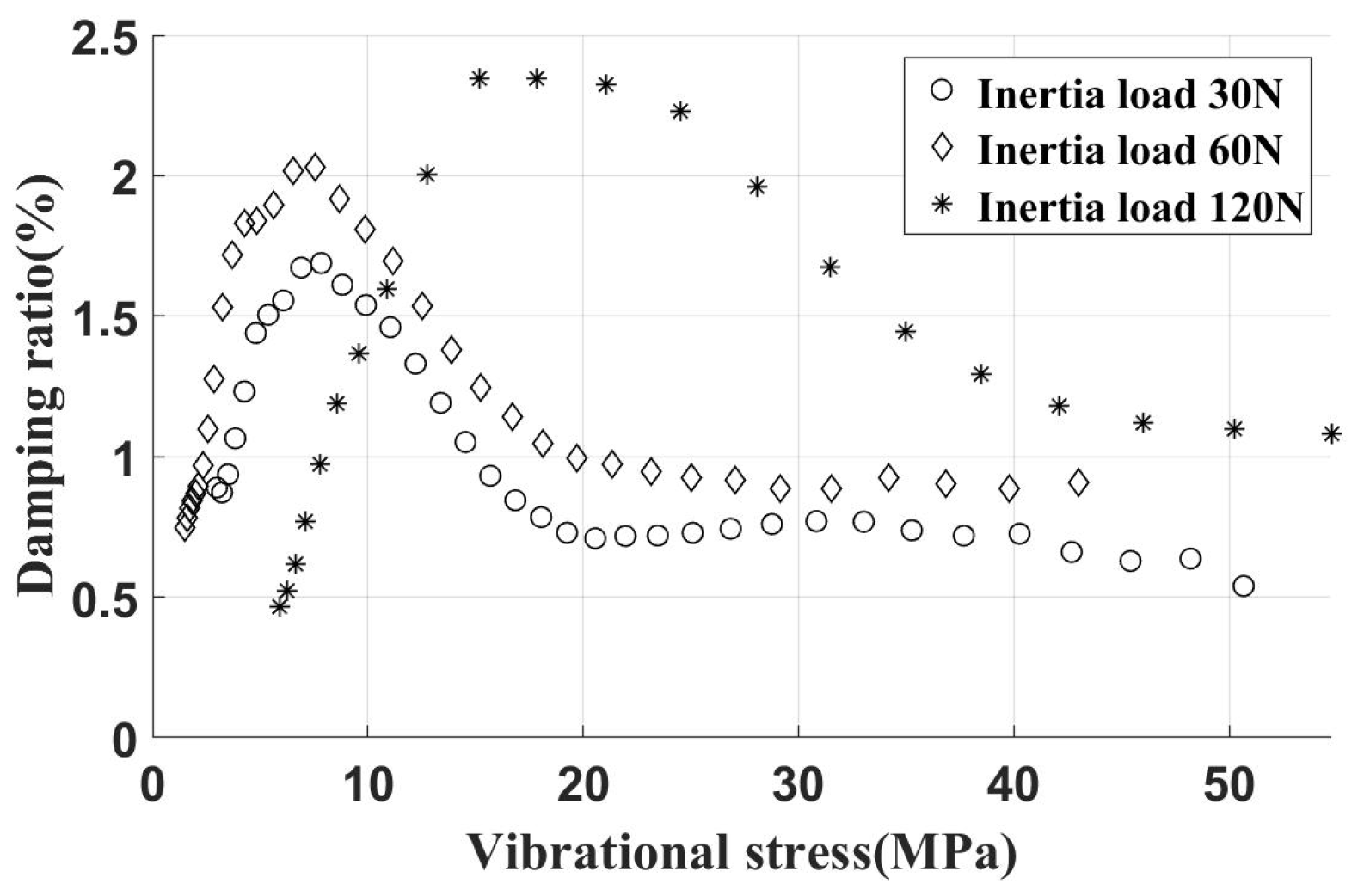
The experimental results for the UPD installed on an inclined contact surface and loaded by varying centrifugal loads are summarized in Figure 16. Observations indicate that with a 30 N inertia load on the damper, the peak damping ratio reaches 1.8%. As the centrifugal load increases further, the peak damping ratio stabilizes at approximately 2.3%, mirroring observations from the frequency sweep test. Beyond a certain inertia load, the tangential contact stiffness shows no significant change. At this stage, only the critical vibration stress increases with the inertia load, while the peak damping ratio remains largely unchanged. This behavior is consistent with simulation results.
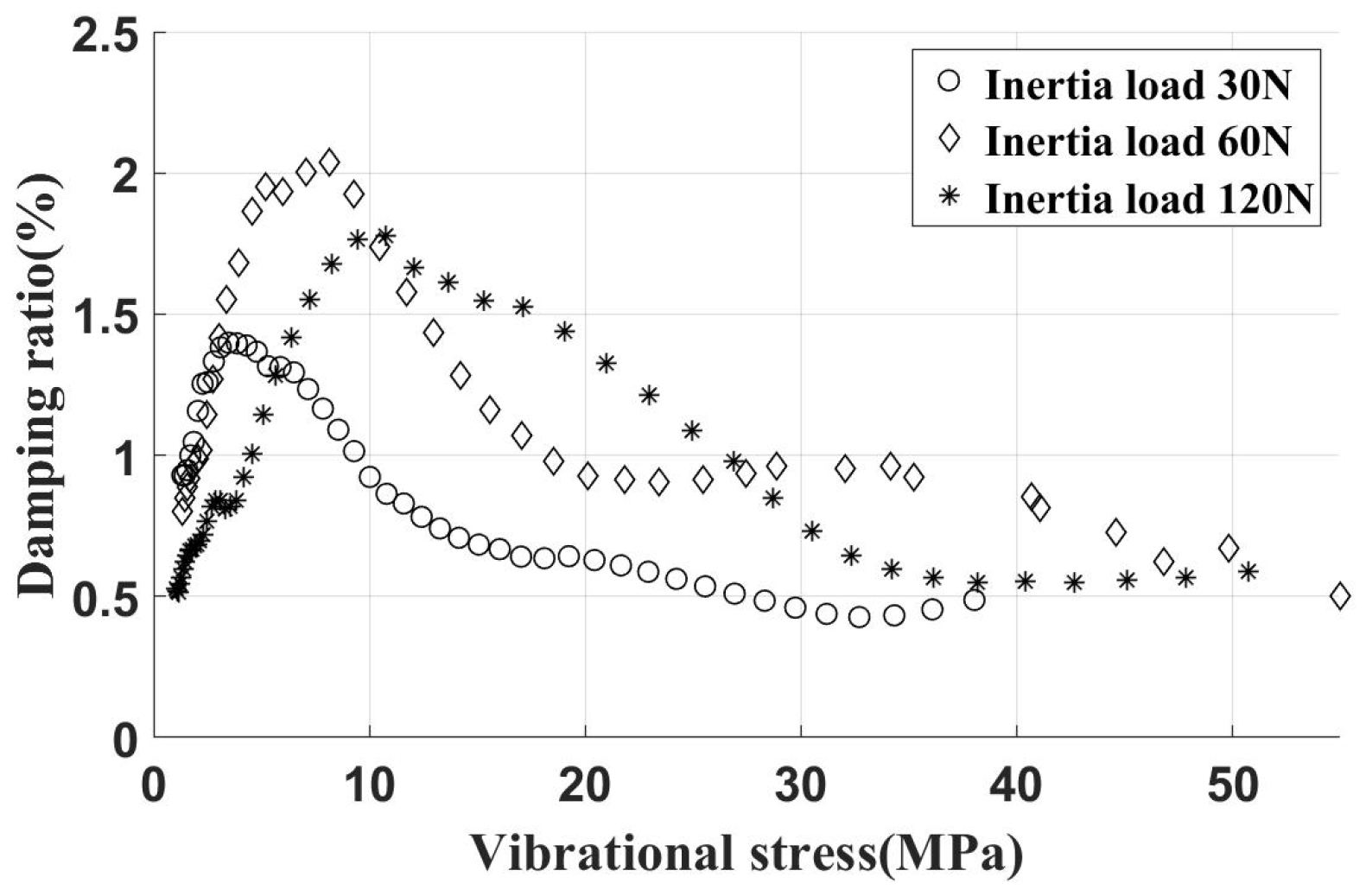
The experimental results of the damper, installed on the vertical contact surface under varied inertia loads, are summarized in Figure 17. After installation, the damper provides a peak dry friction damping ratio of approximately 1.5%. With the damper set at a 30° angle, as shown in Figure 2, the normal contact force on the vertical contact surface was equal to that on the inclined contact surface for the same centrifugal load. Overall, installing the UPD significantly enhances damping effects, effectively reducing vibration stress.
To study the damping characteristics of the UPD, experiments begin with applying normal pressure to the damper on the contact surface, followed by employing a frequency sweep excitation method. This method obtained the FRFs at monitoring points before and after damper installation, evaluating the vibration reduction effect. Each experiment provided a single point on the primary damping ratio characteristic curve of UPD under a specific vibration stress. Obtaining a complete damping ratio curve requires adjusting the excitation force and conducting multiple experiments. This process is time-consuming and inefficient and introduces damping due to the shaker, potentially affecting test outcomes. Conversely, a single damping-free vibration test efficiently yields a damping ratio characteristic curve across a broad range of vibration stress.

4.4. The Influence of Contact Area and Root Extension Length

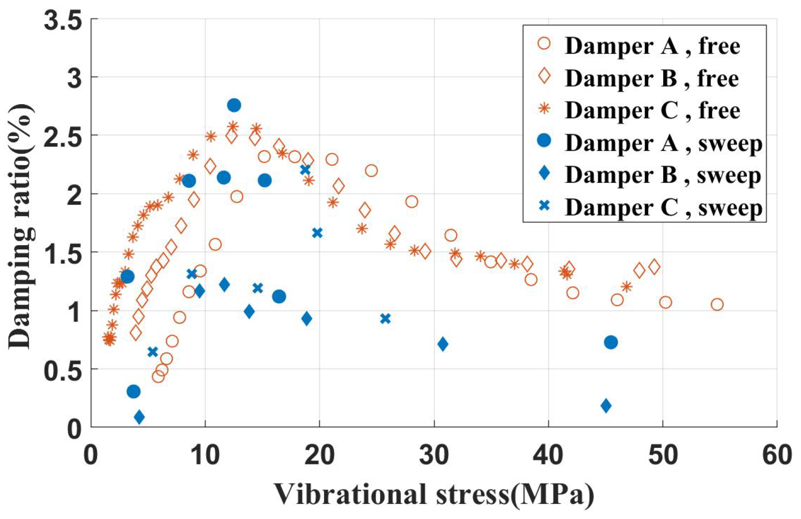
To investigate the effect of the contact area of the UPD on frictional energy dissipation, experimental specimens featuring various contact areas were designed. The key dimensional parameters are listed in Table 5. These specimens, subjected to a 120 N inertial load on inclined contact surfaces, had their resulting test data shown in Figure 18.
Observations reveal that UPDs with varying contact areas on inclined surfaces generally exhibit similar damping ratio characteristics. However, when the contact area is too small (about one-third of the total area), the damping ratio shows significant variations with changing vibration stress, indicating instability in the damper’s damping ratio.
To explore the effect of the root extension length or the modal amplitude of the contact surface on damping characteristics, blade specimens with different shank dimensions were adapted. The dimensions for the shank of each blade specimen are listed in Table 6. Using the same shroud damper with a 120 N inertial load on inclined contact surfaces, the test results are presented in Figure 19.
Comparative analysis clearly shows that the increase of the root extension length enhances the damping ratio characteristics of the damper, resulting in a higher peak damping ratio.
Obvious differences can be found between the results of the free vibration and sweep frequency experiments. This may be related to the following reasons:
  • The initial displacement of the free vibration experiment is not exactly the first bending mode, so the process of vibration is a mix of many modes.
  • During the sweep frequency experiment, both the blade and shaker were vibrating.
  • The exciting force is hard to maintain constant during the vibration.
  • The process of the free vibration experiment is quite short and the wear of the contact surface is ignorable, but the sweep frequency experiments take a long time, so the wear may change the contact parameter.

5. Conclusions

This study conducted resonant vibration tests and damping-free vibration tests on a blade simulation component equipped with UPDs. The analysis of the experiment results yields the following conclusions:
(1) The modal frequency of the first-order bending mode derived from the tests closely aligns with the simulated modal frequency results. Following the installation of UPD devices, the blade modal frequency exhibits a slight increase, with the simulated centrifugal load exerting minimal influence on the frequency.
(2) In the resonant vibration tests conducted without UPD devices, the total damping—comprising material damping of the blade simulation component, blade aerodynamic damping, and interface damping—is estimated to be approximately 1%. However, in the damping-free vibration tests, the damping ratio attributed to the test setup itself is approximately 0.33%. The primary difference between the two can be attributed to the material damping contributed by the resonator connection device (resonator head and force rod) during the resonant vibration tests, as well as the internal structure of the resonator that contributes to damping effects. The peak damping ratio achieved by the inclined contact surface UPD device fluctuates in response to changes in the tangential contact stiffness. Overall, the UPD device markedly enhances the damping effect, thereby significantly reducing vibration stress.
(3) Adjusting the inertial load of the damper primarily affects the critical vibration stress, having minimal impact on the peak damping ratio. The damping ratio characteristics derived from simulation analysis correspond to this pattern. Sensitivity tests on the blade root length reveal that with an increase in the blade root length, the damping effect of the UPD significantly intensifies.
(4) It is crucial to note that although the aforementioned results and patterns were derived under non-rotational conditions, they retain significant implications for the design of practical UPDs. The experimental results presented in this study not only validate the analytical methods developed in previous research but also ensure that the systematic conclusions can be effectively applied and verified in the design of aircraft engines.

Author Contributions

Conceptualization, D.L.; methodology, C.D.; software, C.D.; validation, D.L. and H.L.; formal analysis, C.D.; investigation, D.L.; resources, D.L. and H.L.; writing—original draft preparation, D.L. and C.D.; writing—review and editing, D.L.; visualization, C.D.; supervision, H.L. and G.M.; project administration, H.L. and G.M.; funding measurement, D.L. and G.M. All authors have read and agreed to the published version of the manuscript.

Funding

This work was supported by the National Natural Science Foundation of China (Grant No. U23B6001).

Data Availability Statement

Data are contained within the article.

Conflicts of Interest

Author Di Li was employed by the company Commerical Aircraft Engine Company Limited, Aero Engine (Group) Corporation of China. The remaining authors declare that the research was conducted in the absence of any commercial or financial relationships that could be construed as a potential conflict of interest.

References

  1. Fang, M.; Wang, Y. Efficient numerical prediction of blade forced response under inlet distortion. Aerosp. Sci. Technol. 2023, 142, 108612. [Google Scholar] [CrossRef]
  2. Fang, M.; Wang, Y. Intentional Mistuning Effect on the Blisk Vibration with Aerodynamic Damping. AIAA J. 2022, 60, 3884–3893. [Google Scholar] [CrossRef]
  3. Wu, Y.; Wang, H.; Fan, Y.; Li, L. On the network of synchronized switch damping for blisks. Mech. Syst. Signal Process. 2023, 184, 109695. [Google Scholar] [CrossRef]
  4. Menq, C.H.; Chidamparam, P.; Griffin, J.H. Friction damping of two-dimensional motion and its application in vibration control. J. Sound Vib. 1991, 144, 427–447. [Google Scholar] [CrossRef]
  5. Sanliturk, K.Y.; Ewins, D.J. Modelling Two-Dimensional Friction Ccontact and its Application Using Harmonic Balance Method. J. Sound Vib. 1996, 193, 511–523. [Google Scholar] [CrossRef]
  6. Yang, B.D.; Menq, C.H. Modeling of Friction Contact and Its Application to the Design of Shroud Contact. J. Eng. Gas Turbines Power-Trans. ASME 1997, 119, 958–963. [Google Scholar] [CrossRef]
  7. Siewert, C.; Panning, L.; Wallaschek, J.; Richter, C. Multiharmonic Forced Response Analysis of a Turbine Blading Coupled by Nonlinear Contact Forces. J. Eng. Gas Turbines Power 2010, 132, 082501. [Google Scholar] [CrossRef]
  8. Gao, Q.; Fan, Y.; Wu, Y.; Liu, J.; Wang, J.; Li, L. A novel test apparatus to study the mechanism of harmonic normal force on fretting wear. Tribol. Int. 2024, 191, 109091. [Google Scholar] [CrossRef]
  9. Gao, Q.; Fan, Y.; Wu, Y.; Li, L. A harmonic balance-based method to predict nonlinear forced response and temperature rise of dry friction systems including frictional heat transfer. Nonlinear Dyn. 2023, 111, 14263–14291. [Google Scholar] [CrossRef]
  10. Sun, H.; Zhang, D.; Wu, Y.; Shen, Q.; Hu, D. A semi-analytical multi-harmonic balance method on full-3D contact model for dynamic analysis of dry friction systems. Chin. J. Aeronaut. 2024, 37, 309–329. [Google Scholar] [CrossRef]
  11. Wu, Y.; Li, L.; Fan, Y.; Zucca, S.; Gastaldi, C.; Ma, H. Design of dry friction and piezoelectric hybrid ring dampers for integrally bladed disks based on complex nonlinear modes. Comput. Struct. 2020, 233, 106237. [Google Scholar] [CrossRef]
  12. Wu, Y.; Li, L.; Fan, Y.; Ma, H.; Wang, W.; Christen, J.L.; Ichchou, M. Design of semi-active dry friction dampers for steady-state vibration: Sensitivity analysis and experimental studies. J. Sound Vib. 2019, 459, 114850. [Google Scholar] [CrossRef]
  13. Ferhatoglu, E.; Zucca, S. Determination of periodic response limits among multiple solutions for mechanical systems with wedge dampers. J. Sound Vib. 2021, 494, 115900. [Google Scholar] [CrossRef]
  14. Denimal, E.; Wong, C.; Salles, L.; Pesaresi, L. On the Efficiency of a Conical Underplatform Damper for Turbines. J. Eng. Gas Turbines Power 2021, 143, 021020. [Google Scholar] [CrossRef]
  15. Gastaldi, C.; Berruti, T.M.; Gola, M.M. Best practices for underplatform damper designers. Proc. Inst. Mech. Eng. Part C. J. Mech. Eng. Sci. 2018, 232. [Google Scholar] [CrossRef]
  16. Gastaldi, C.; Berruti, T.M. Direct measurement of the damping and stiffening capabilities of cylindrical underplatform dampers. Mech. Syst. Signal Process. 2020, 139, 106632. [Google Scholar] [CrossRef]
  17. Gastaldi, C.; Berruti, T.M.; Gola, M.M. A novel test rig for friction parameters measurement on underplatform dampers. Int. J. Solids Struct. 2020, 185–186, 170–181. [Google Scholar] [CrossRef]
  18. Panning, L.; Popp, K.; Sextro, W.; Gotting, F.; Kayser, A.; Wolter, I. Asymmetrical Underplatform Dampers in Gas Turbine Bladings: Theory and Application. In Proceedings of the Turbo Expo: Power for Land, Sea, and Air, Vienna, Austria, 14–17 June 2004; Volume 6: Turbo Expo 2004, pp. 269–280. [Google Scholar] [CrossRef]
  19. Cigeroglu, E.; An, N.; Menq, C.H. A microslip friction model with normal load variation induced by normal motion. Nonlinear Dyn. 2007, 50, 609–626. [Google Scholar] [CrossRef]
  20. Salas, M.G.; Bladh, R.; Mårtensson, H.; Petrie-Repar, P.; Fransson, T.; Vogt, D.M. Forced Response Analysis of a Mistuned, Compressor Blisk Comparing Three Different Reduced Order Model Approaches. J. Eng. Gas Turbines Power 2017, 139, 062501. [Google Scholar] [CrossRef]
  21. Mehrdad Pourkiaee, S.; Zucca, S. A Reduced Order Model for Nonlinear Dynamics of Mistuned Bladed Disks with Shroud Friction Contacts. J. Eng. Gas Turbines Power 2018, 141, 011031. [Google Scholar] [CrossRef]
  22. Benfield, W.A.; Hruda, R.F. Vibration Analysis of Structures by Component Mode Substitution. Aiaa J. 1971, 9, 1255–1261. [Google Scholar] [CrossRef]
  23. Gola, M.M. A general geometrical theory of turbine blade underplatform asymmetric dampers. Mech. Syst. Signal Process. 2023, 191, 110167. [Google Scholar] [CrossRef]
  24. Rani, S. Parametric Evaluation and Dynamic Analysis of Turbine Blades–Damper Assembly Using Bond Graph Technique. J. Vib. Eng. Technol. 2023, 12, 681–693. [Google Scholar] [CrossRef]
  25. Pesaresi, L.; Salles, L.; Jones, A.; Green, J.; Schwingshackl, C. Modelling the nonlinear behaviour of an underplatform damper test rig for turbine applications. Mech. Syst. Signal Process. 2017, 85, 662–679. [Google Scholar] [CrossRef]
  26. Pesaresi, L.; Stender, M.; Ruffini, V.; Schwingshackl, C.W. DIC Measurement of the Kinematics of a Friction Damper for Turbine Applications. In Proceedings of the Dynamics of Coupled Structures; Allen, M.S., Mayes, R.L., Rixen, D.J., Eds.; Springer: Cham, Switzerland, 2017; Volume 4, pp. 93–101. [Google Scholar]
  27. Zhang, D.; Gao, B.; Hong, J.; Fu, J.; Ge, X. Experimental investigation on dynamic response of flat blades with underplatform dampers. Chin. J. Aeronaut. 2019, 32, 2667–2678. [Google Scholar] [CrossRef]
  28. Ferhatoglu, E.; Gastaldi, C.; Botto, D.; Zucca, S. An experimental and computational comparison of the dynamic response variability in a turbine blade with under-platform dampers. Mech. Syst. Signal Process. 2022, 172, 108987. [Google Scholar] [CrossRef]
  29. Ferhatoglu, E.; Zucca, S. On the non-uniqueness of friction forces and the systematic computation of dynamic response boundaries for turbine bladed disks with contacts. Mech. Syst. Signal Process. 2021, 160, 107917. [Google Scholar] [CrossRef]
  30. Hoffmann, T.; Panning-von Scheidt, L.; Wallaschek, J. Measured and Simulated Forced Response of a Rotating Turbine Disk With Asymmetric and Cylindrical Underplatform Dampers. J. Eng. Gas Turbines Power 2020, 142, 051002. [Google Scholar] [CrossRef]
  31. Gao, S.; Wang, Y.; Sun, Z. An Energy Method for Assessing the Damping of Turbine Blade Underplatform Damper and Forced Response Verification. In Proceedings of the Turbo Expo: Power for Land, Sea, and Air, Virtual, 21–25 September 2020; Volume 11: Structures and Dynamics: Structural Mechanics, Vibration, and Damping; Supercritical CO2. p. V011T30A010. [Google Scholar] [CrossRef]
  32. Gao, S.; Wang, Y.; Sun, Z.; Chen, S. A Prediction Method with Altering Equivalent Stiffness for Damping Evaluation of Shrouded Bladed Disk Dynamic Systems. Symmetry 2021, 13, 413. [Google Scholar] [CrossRef]
  33. Chen, S.; Wang, Y.; Wei, D.; Luo, Y.; Gao, S. Vibration Analysis and Methods of Dry Friction Damping of Tubed Vortex Reducer. In Proceedings of the Turbo Expo: Power for Land, Sea, and Air, Virtual, 21–25 September 2020; Volume 11: Structures and Dynamics: Structural Mechanics, Vibration, and Damping; Supercritical CO2. p. V011T30A001. [Google Scholar] [CrossRef]
  34. Amabili, M. Nonlinear damping in large-amplitude vibrations: Modelling and experiments. Nonlinear Dyn. 2018, 93, 5–18. [Google Scholar] [CrossRef]
  35. Amabili, M. Derivation of nonlinear damping from viscoelasticity in case of nonlinear vibrations. Nonlinear Dyn. 2019, 97, 1785–1797. [Google Scholar] [CrossRef]
  36. Grosso, P.; Felice, A.D.; Sorrentino, S. A method for the experimental identification of equivalent viscoelastic models from vibration of thin plates. Mech. Syst. Signal Process. 2021, 153, 107527. [Google Scholar] [CrossRef]
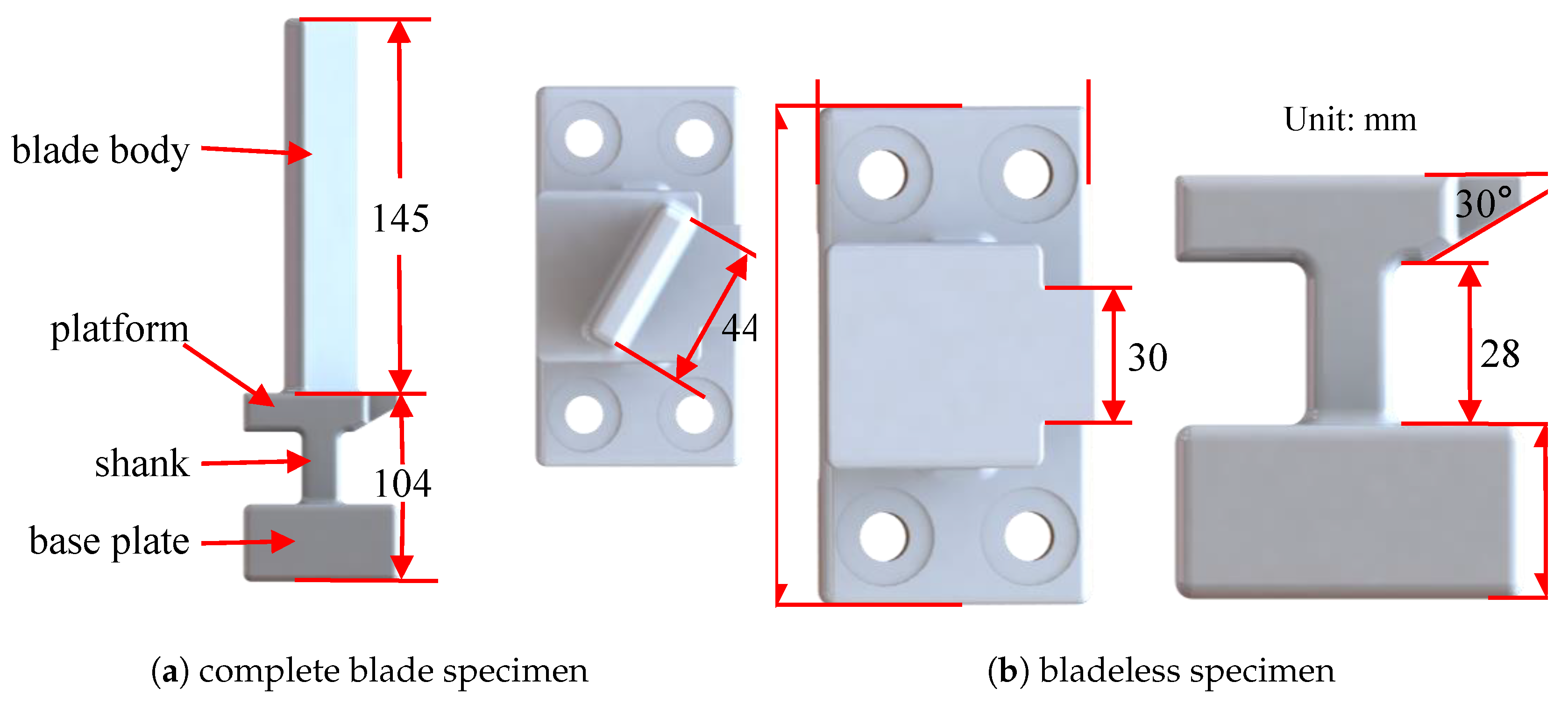
Figure 1. Model of blade specimen.
Machines 12 00461 g001
Figure 2. Model of tri-prism UPD test pieces.
Machines 12 00461 g002
Figure 3. UPD installation diagram.
Machines 12 00461 g003
Figure 4. Vibration test device.
Machines 12 00461 g004
Figure 5. Location of excitation and monitoring points.
Machines 12 00461 g005
Figure 6. The flowchart of damping-free vibration experiment.
Machines 12 00461 g006
Figure 7. Friction hysteresis curve of macro sliding model.
Machines 12 00461 g007
Figure 8. The total displacement of first-order bending mode of the blade specimen.
Machines 12 00461 g008
Figure 9. Schematic diagram illustrating modal displacement extraction.
Machines 12 00461 g009
Figure 10. Damping characteristic curve simulation results.
Machines 12 00461 g010
Figure 11. Experimental and simulation results (damper installed on incline contact surface, different inertial loads). (a) Experimental and simulation damping ratio characteristic curves. (b) FRFs of 120 N inertial loads.
Machines 12 00461 g011
Figure 12. Damping characteristics of blade test piece (damper installed on vertical contact surface, different inertial loads).
Machines 12 00461 g012
Figure 13. Free vibration test data.
Machines 12 00461 g013
Figure 14. Damping characteristic curve of free vibration without underplatform damper.
Machines 12 00461 g014
Figure 15. Damping characteristics of blade test piece (damper installed on incline contact surface, inertial load 120 N).
Machines 12 00461 g015
Figure 16. Free vibration test data (damper installed on incline contact surface, different inertial loads).
Machines 12 00461 g016
Figure 17. Free vibration test data (damper installed on vertical contact surface, different inertial loads).
Machines 12 00461 g017
Figure 18. Damping characteristics of blade specimens (different contact area of UPDs).
Machines 12 00461 g018
Figure 19. Damping characteristics of different blade specimens.
Machines 12 00461 g019
Table 1. Material property of 45 # steel.
Dense ( kg / m 3 )Poisson RatioYoung’s Modulus (GPa)
78100.269201
Table 2. Parameters for vibration reduction in UPDs.
ParametersValues
Frequency f / Hz 328.91
Inclined contact surface radial modal displacement A x , r / mm 116
Inclined contact surface tangential modal displacement A x , θ / mm 97
Vertical contact surface radial modal displacement A z , r / mm −116
Vertical contact surface tangential modal displacement A z , θ / mm 103
Examination of modal equivalent stress at a nodal point σ modal / MPa 4.58 × 10 5
Modal kinetic energy W modal / J 2.14 × 10 6
Frictional coefficient μ 0.3
Tangential contact stiffness k t / ( N / mm ) 30,000
Table 3. The normal pressure on the contact surface corresponding to different inertial loads (unit: MPa).
Inertial LoadNormal Pressure on Inclined Contact SurfaceNormal Pressure on a Direct Contact Surface
3034.6417.32
6069.2834.64
90103.9251.96
120138.5669.28
Table 4. First-order bending vibration frequency of blade test piece (unit: Hz).
ParametersValues
Simulated frequency f s 328.91
Test frequency without dampers f 0 322.57
Test frequency with 30 N inertial load f 30 327.15
Test frequency with 120 N inertial load f 120 327.19
Table 5. Dimension of inclined contact area of underplatform damper test pieces (unit: mm).
Specimen NumberContact LengthContact Width
A3316
B2216
C1116
Table 6. Length of the shank (unit: mm).
Specimen NumberRoot Extension Length
I28
II38
III48
Disclaimer/Publisher’s Note: The statements, opinions and data contained in all publications are solely those of the individual author(s) and contributor(s) and not of MDPI and/or the editor(s). MDPI and/or the editor(s) disclaim responsibility for any injury to people or property resulting from any ideas, methods, instructions or products referred to in the content.