Article

Cloud-Based Remote Real-Time Monitoring and Control System for Spring Fatigue Testing Machine

1
Yanqi Lake (Beijing) Institute of Basic Manufacturing Technology Research, China Academy of Machinery Science and Technology, Beijing 101400, China
2
China Productivity Center for Machinery, China Academy of Machinery Science and Technology, Beijing 100044, China
3
China Nuclear Power Engineering Co., Ltd., Beijing 100048, China
*
Author to whom correspondence should be addressed.
Machines 2024, 12(7), 462; https://doi.org/10.3390/machines12070462
Submission received: 6 April 2024 / Revised: 20 June 2024 / Accepted: 24 June 2024 / Published: 9 July 2024
(This article belongs to the Section Machines Testing and Maintenance)

Abstract

:
In recent years, the utilization of cloud technology has witnessed a surge, particularly in the domains of industrial automation and intelligent scenarios. However, the prevailing spring fatigue testing machine is still in the traditional single-machine working mode. In this mode, there are many problems such as low automation of testing equipment, poor experimental site environment, and the need for experimenters to be on duty for a long time. In order to solve the above problems, this paper builds a cloud-based remote monitoring and control system based on the high-temperature constant-force spring fatigue testing machine. The system is based on Browser/Server architecture, and clients can access it anytime and anywhere using a browser in a public network environment. The server is hosted on a public cloud platform and includes website service, data storage service, WebSocket real-time communication service, and remote video monitoring service. Clients can remotely monitor and control the testing machine in real time through the cloud. After experimental verification, the real-time monitoring and control messages delay is 11 ms, and the video monitoring delay is 291 ms, which can meet the actual needs of remote spring fatigue testing. This remote monitoring and control system improves the automation of the spring fatigue testing machine and improves the working environment of the experimenters. In addition, it can be applied to other reliability testing machines in the laboratory, and can further help build a workshop-level remote monitoring and control platform.

1. Introduction

Springs are an essential component of mechanical systems, playing a significant role in both production and daily life. To ensure that the springs can work safely and stably during their service period, it is necessary to conduct various performance tests before they leave the factory. For high-temperature constant-force springs, common reliability tests include fatigue experiments and creep experiments, which are used to predict the service life of the springs. These experiments are mainly completed by a constant-force spring high-temperature fatigue testing machine [1,2].
However, most of the current high-temperature fatigue testing machines for constant-force springs are traditional single-machine equipment [3,4], which have many problems: the equipment has low automation and requires manual on-site operation; the experimental environment is poor, and there are high temperatures, vibrations, and noises at the testing site, which may have an impact on the health of the experimenter; the experiment lasts for a long time, and the experimental process is monotonous and boring; and the information interconnection is poor, and the alarm information cannot be effectively transmitted, requiring long-term monitoring by the experimenter.
Meanwhile, in recent years, cloud technology has developed vigorously and has played an important role in many fields such as intelligent manufacturing and unmanned factories [5,6,7,8]. Cloud service refers to a place on a network infrastructure where information technology (IT) and computing resources, such as computer hardware, operating systems, networks, storage, databases, and even entire software applications, are available to users instantly on demand. Users can use the cloud as an intermediate bridge, and use cloud resources to store and handle process data, thereby achieving remote equipment management, monitoring, and control more conveniently and quickly.
In summary, considering the problems existing in remote equipment monitoring and control, this paper combines the advantages of cloud technology to design a cloud-based remote monitoring and control system for spring fatigue testing machines. This system is based on the hardware of the constant-force spring fatigue testing machine. The cloud server serves as a bridge to build a remote monitoring and control network, enabling status monitoring and control of remote equipment, storage of experimental data, and monitoring of on-site images. The system has the following main contributions:
1. The system solved the problems of traditional fatigue testing machines such as low informatization, poor experimental environment, and high labor costs.
2. The system uses the cloud as a bridge to realize end-to-end information transmission in a public network environment. At the same time, the cloud also integrates website service, database service, and video monitoring service.
3. Furthermore, the system is not limited to spring fatigue testing machines. Other machines in the testing laboratory can be easily integrated into the system, and a multi-device remote monitoring and control platform can be quickly built.

2. Related Works

Remote monitoring and control technology is mainly concentrated in several fields such as industry, agriculture, education, electricity, mining, transportation, smart home, etc. Many scholars have conducted research on this.
In the field of mechanical manufacturing, in order to optimize the structure of mechanical systems and improve work efficiency, many scholars have introduced cloud technology into existing systems. Riccardo presents a control-loop performance monitoring system, which obtains remote sensor data in JSON format through the MQTT publish–subscribe mechanism, stores the data in the cloud database, and displays them on the web browser after evaluating the loop status. In case of any abnormality, the system will notify the experimenter via email [9]. Md Tahmid built a cloud-based digital twin framework to monitor and control a remote assembly system. The system uses the MQTT protocol to store sensor data in a Google Cloud database and can send simple control instructions such as start and stop to the robot [10]. Liu et al. built a cloud-based digital twin manufacturing system, which also uses MQTT to store sensor data in the cloud database. The difference is that this system is based on a local private cloud system. The web browser communicates with the private cloud through RESTful APIs to monitor and control remote devices. Finally, the system delay is 1.24 s [11]. These systems are mainly for monitoring, and their control capabilities are relatively weak. Remote control requires higher real-time performance of the system, but the remote communication capabilities of these systems have not been tested in detail.
In the field of engineering and science education, due to the uneven distribution and inaccessibility of educational resources, many scholars have carried out remote experimental research. Students can remotely access experimental equipment, conduct experiments, and complete learning tasks. The remote operating system designed by Stefanuto and Vanegas uses the laboratory computer as a cloud server, opens the port to the public network, and uses a publish–subscribe mechanism to communicate between the web application and the robot server, ultimately realizing remote robot control. Control, the remote communication delay is about 500 ms [12,13]. Viswanadh proposed a remote laboratory solution, using Blynk Cloud Service as a communication intermediary, using HTTP(S) GET and POST requests to establish communication transfer with a remote IoT component; the system also used p2p communication to establish WebRTC video live broadcast, with a video delay of about 200–400 ms [14]. However, the monitoring and control system in the education field has high latency and has not been used in engineering practice.
In the field of actual mechanical reliability experiments, Feng et al. developed an ARM-based remote monitoring system for creep testing machines, which consists of an ARM controller, a cloud server, and a client. The ARM controller collects sensor parameters of the creep testing machine through the RS485 bus and uploads them to the database of the cloud server through Ethernet. The database is the bridge between the experimenter and the testing machine. The experimenter can monitor data, configure parameters, and start and stop the remote testing machine by reading and writing the cloud database [15]. Xu et al. developed a wireless remote monitoring and control test system based on ZigBee technology and LabVIEW. The system collects sensor information of equipment through ZigBee wireless, and can realize remote monitoring of the test equipment with the help of local LabVIEW web services, but cannot remotely control it [16]. Yang et al. built a private cloud on the internal LAN and established web services and SQL server database services on the cloud. The experimenter accessed the database through the website on the public network. The website used Ajax controls to refresh the page data once a second to achieve remote monitoring of the test system, but remote control was also not possible [17]. Qi et al. proposed a multi-channel fatigue test IoT remote monitoring system. The system consists of a cloud platform, a client, and a test server. The cloud platform is responsible for information storage and information communication, and the web client is responsible for monitoring and visual display of real-time data. The system realizes the functions of data collection, online monitoring, and information management of fatigue test equipment. The real-time communication of this system is completed through Ajax short polling and WebSocket, with a polling interval of 1.5 s [18]. However, this system mainly focuses on the status monitoring of remote devices, and the software architecture of the system is relatively complex.
The above research shows that cloud technology is increasingly used in the field of traditional machinery, and has produced good results. However, in terms of cloud-based remote monitoring and control, there are still many common problems in the current solutions. For different application scenarios, the architecture of remote monitoring and control systems and the types of technologies used are diverse and have their own characteristics. At present, most remote monitoring and control systems are mainly based on monitoring, and remote control cannot be achieved or can only achieve simple control instructions. Furthermore, these control systems also have problems with high latency and poor real-time performance.
Therefore, this paper introduces the cloud into traditional fatigue detection equipment, and uses the technical advantages of the cloud to propose a system solution for monitoring and control with high real-time performance and stability, and capable of end-to-end remote communication, which solves the existing problems of traditional fatigue equipment.

3. System Architecture

The cloud-based spring fatigue testing machine remote monitoring and control system can be divided into the following three components according to geographical distribution, as shown in Figure 1:
1. Remote facilities: spring fatigue testing machine, which includes PLC, actuators, sensors, heating furnaces, and other auxiliary components; remote host computer and host computer software; surveillance camera.
2. Cloud services: as an intermediate bridge, it provides clients with website service, WebSocket communication service, database service, and video monitoring service.
3. Client: computer and browser application that can access the Internet.
The relationship between each component is shown in Figure 1. Each component coordinates with each other to ensure the integrity of the system. The components of each subsystem, their interconnections, and their mode of operation are further described below.

4. Equipment Parts

4.1. Remote Facilities

4.1.1. High-Temperature Constant-Force Spring Fatigue Testing Machine

The high-temperature constant-force spring fatigue testing machine can test the fatigue performance and creep characteristics of the spring under high-temperature conditions by loading periodic variable loads, and further predict the life of the spring.
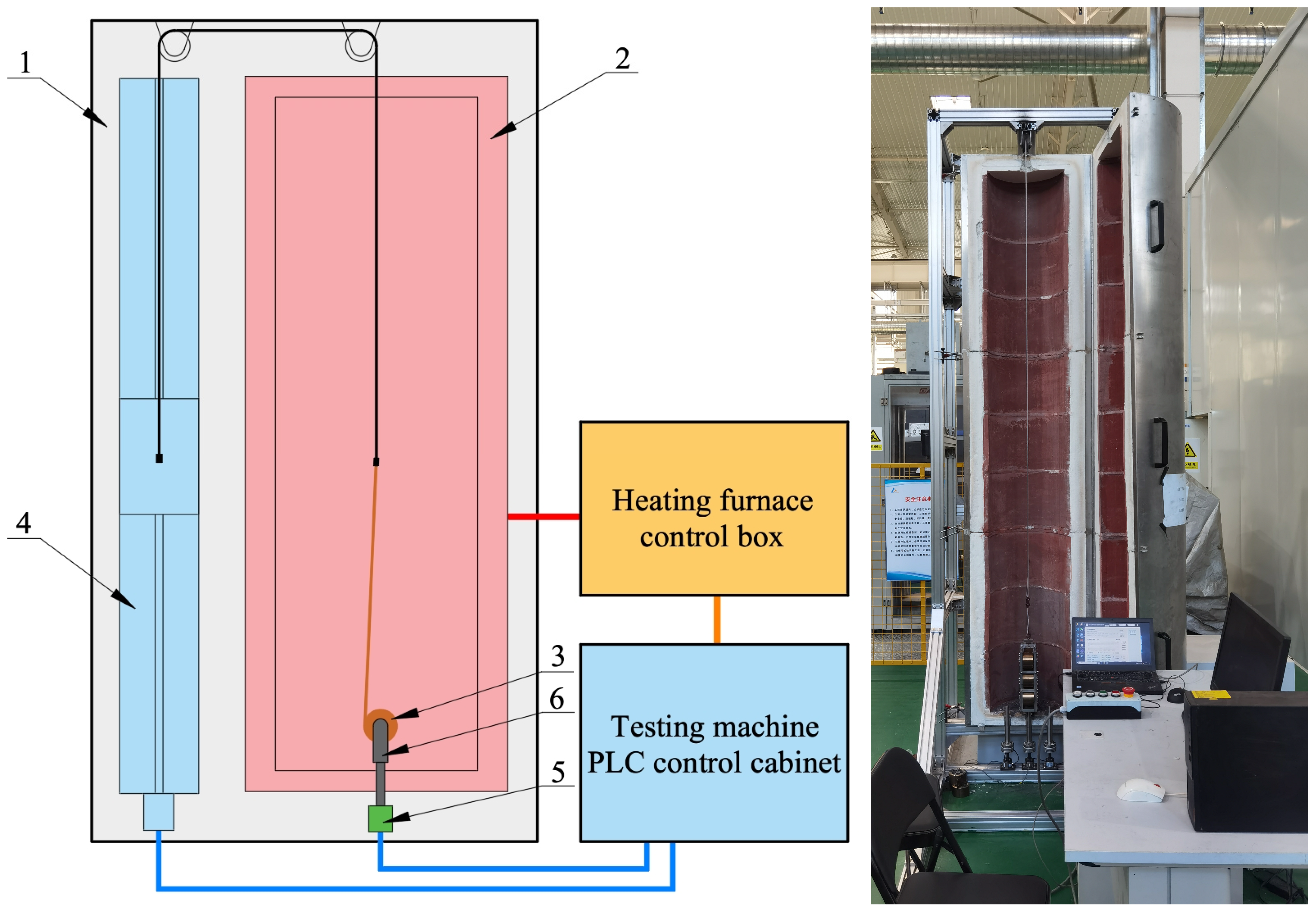
The equipment mainly consists of a testing machine bracket, tubular heating furnace, motion module, spring clamps, tension and pressure sensors, heating furnace temperature control boxes, and testing machine control cabinet, as shown in Figure 2.
  • The test machine bracket is made of standard aluminum profiles with a cross-section of 60 × 60 mm.
  • The tubular furnace is a customized product based on the constant force spring fatigue test conditions, and it comes from Xingyuan Electric Power Appliance Factory, Baoying, China. It has a diameter of 650 mm, a length of 2700 mm, an inner cavity diameter of 350 mm, a length of 2500 mm, and comes with a temperature control cabinet. Its operating temperature is ≤500 °C, the temperature accuracy range is ±2 °C, and the total power is about 25 KW. The tubular heating furnace is installed vertically on the bracket. Due to the high-temperature environment in the heating furnace, the experimental temperature is 300 °C, and the motion module and the tension and pressure sensor are arranged outside the heating furnace to ensure that they can work normally. In order to ensure that the experiment is carried out in a constant temperature environment for the spring, small holes are left above and below the heating furnace. The spring clamp fixes the spring inside the heating furnace through the small holes at the bottom to ensure that the environmental temperature of the spring is constant during the experiment.
  • The motion module comes from Yancheng Gaobo Transmission Technology Co., Ltd., Dongtai, China. The model is GX150 and the motion stroke is 1800 mm. The motion module is fixed on the back side of the heating furnace, and a steel cable is used to pull a constant-force spring through a small hole above the heating furnace for periodic loading, with a movement speed of 0.2 m/s.
  • The tension and pressure sensor is from Changzhou Allison Technology Co., Ltd., Changzhou, China. The model is AR-DN31, with a range of 100 N and 500 N. Its accuracy is 0.1%. The tension and pressure sensor is fixed between the bracket and the spring clamp just below the bottom of the heating furnace to detect the tension data of the constant-force spring during the experiment.
  • The self-designed spring fixture can realize one, two, or three pairs of spring installation forms. The tension of a single spring is 60 N, and the tension of a pair of springs ranges from 120 N to 360 N.
  • Siemens PLC (Siemens, Munich, Germany) centrally connects the heating furnace control cabinet, motion module, and tension and pressure sensor to the control cabinet for data collection and control.

4.1.2. Spring Fatigue Testing Machine Control System

The control system mainly completes the control of the constant-force spring fatigue testing machine and returns equipment status information to the host computer. The control system mainly includes the host computer, Siemens PLC controller, motion module, tension and pressure sensor, proximity sensor, and temperature control box and other parts, as shown in Figure 3.
The servo motor kit used in the motion module comes from Zhejiang Yichuan Motor Co., Ltd., Taizhou, China. The model of the servo drive is A1-SVD15A and the model of the motor is 80st_m04025. The servo drive input power is three-phase AC220V, the output current is 15 A, and the output power is ≤10 KW. The motor has a rated power of 1 KW, a rated torque of 4 NM, a rated speed of 2500 r/min, and is equipped with a 2500-line incremental encoder and a brake. The motion control mode is the position control mode, and the encoder provides the system with accurate displacement and speed information.
The metal induction proximity switch used on the motion module comes from Shenzhen Xingyi Electric Co., Ltd., Shenzhen, China. The model of the proximity switch is SN04-N, the working voltage is DC5-30V, and the sensing distance is 4 mm. The three proximity switch sensors are responsible for marking the upper limit, lower limit, and zero position to ensure the accuracy and safety of the motor movement.
The temperature controller box collects the temperature value in the heating furnace through three probe-type armored thermocouples. The thermocouple sensor comes from China Jiunuotai Automation Technology Co., Ltd., Dongtai, China, model WRN-191, the probe diameter is 3 mm, the length is 250 mm, and the temperature measurement range is 0–800 °C. After collecting the temperature, the temperature controller box sends it to the PLC via RS485.
The SIMATIC S7-1200 series PLC used in the control system includes 3 modules:
1. Central processing unit module (CPU). Its model is CPU1214C DC/DC/DC, which contains 14 inputs and 10 outputs. The output part of this module is mainly responsible for completing motor motion pulse control and signal light output; the input part of this module is mainly responsible for receiving manual control signals, proximity sensor signals, motor encoder pulse signals, and alarm signals; in addition, the module is also responsible for logic control, communicating with the PC host computer, and communicating with the other two modules.
2. Communication module. Its model is CM1241 RS422/485, with RS422 or 485 communication capabilities. This module is mainly responsible for RS485 communication with the temperature control box to realize the temperature acquisition and control of the heating furnace.
3. Analog input module. Its model is SM1231 AI 4×16 bit, which is mainly responsible for acquiring the force values of three tension and pressure sensors.
The host computer communicates with the PLC through Ethernet, the host computer sends control instructions to the PLC, and the PLC returns the device status parameters in real time.

4.1.3. Host Computer Software

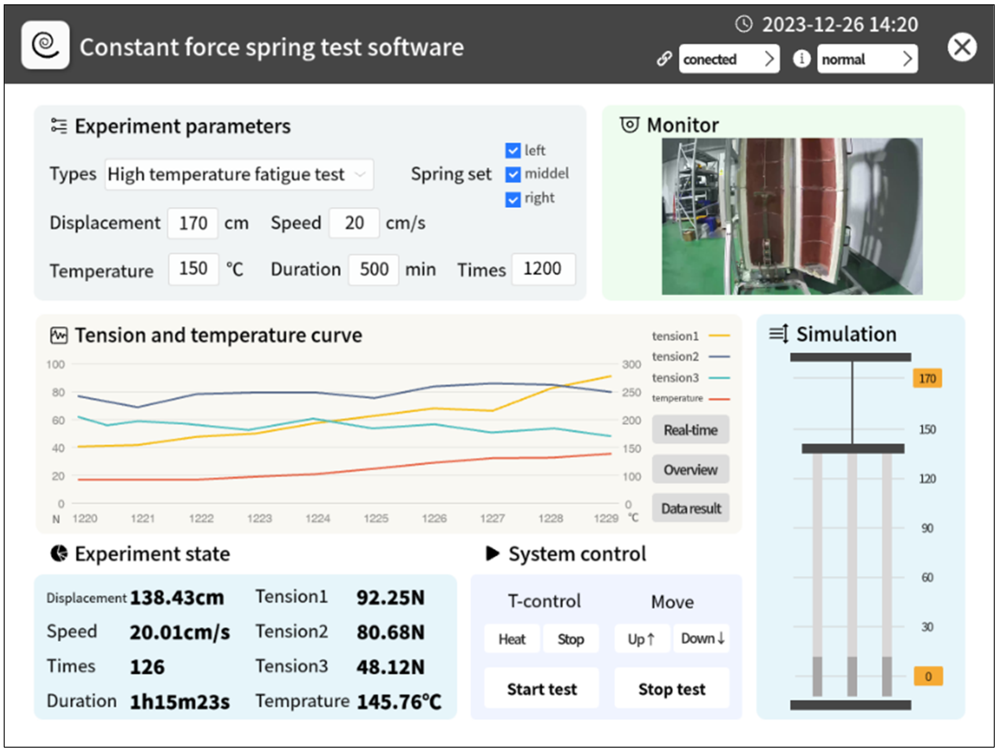
The host computer software is the key for the spring fatigue testing machine to communicate with the outside world. The software is written by Visual Studio 2022, and the development language is C#. The software has functions such as connecting to PLC, setting experimental parameters, displaying and saving experiment data, controlling equipment, connecting to the local database, and connecting to cloud services (database server, WebSocket server, and monitoring server). The software interface is shown in Figure 4 below.
The software’s downward communication with Siemens PLC relies on the S7.net library [19]; it sends the control parameters required for the experiment to the PLC to realize on-site control of the machine. At the same time, it receives the machine data uploaded by the PLC and displays them on the page. In addition, the software also saves the machine test data in the local MySQL database as a safe backup.
The software communicates upwards with the cloud server through Ethernet and mainly includes three parts: first, it can save the experimental data to the cloud database for viewing by the Web client; second, it communicates with the WebSocket server in real time and two-way to realize remote monitoring and control of the testing machine; third, it collects camera footage in real time and pushes the video stream to the video surveillance server to achieve remote video monitoring.

4.2. Cloud Services

The internal network within the laboratory is generally a local area network, but remote access generally requires communication across local area networks to traverse the public network. In this paper, the remote monitoring and control system uses a public cloud server as an intermediary. Both the client and the remote machine communicate with the cloud server. The cloud server serves as an intermediate bridge, providing information storage, information forwarding, and other services, realizing end-to-end remote real-time communication. The cloud server structure is shown in Figure 5.
Currently, cloud service is mainly divided into three models, namely, Infrastructure as a Service (IaaS), Software as a Service (SaaS), and Platform as a Service (PaaS) [20]. Each of the three modes has its own advantages and disadvantages. Among them, under the IAAS cloud service mode, users have a higher degree of freedom, which facilitates subsequent program development and testing, and personalized device connections.
This system selected the ECS (Elastic Compute Service) of Alibaba Cloud Computing Co., Ltd., Hangzhou, China, based on IAAS mode. In order to test the impact of different server addresses on connection performance, based on the test node address provided by Alibaba Cloud, the ping tool was used to test the latency in different regions. The data obtained are shown in Table 1 below.
The test address is located in Beijing, China. After testing, it was found that the latency in North China 2, which is closest to the test address, is as low as 7 ms, while the latency in Shanghai is 29 ms, Tokyo is 75 ms, London is 172 ms, and Dubai is 354 ms. The closer the distance between the user and the server, the faster the relative speed and the lower the latency. Therefore, the final server address was selected as North China 2 (Beijing), which is located in the same area as the company’s location.

4.2.1. MySQL System Database

In order to record and store relevant data generated during the operation of the remote monitoring and control system, a MySQL database was built on the cloud server. The database contains multiple data tables for storing personnel, equipment, experiments, and other data.
The database mainly contains the following information: communication records between the client and remote host computer; online and offline information of the web client and remote machine; experimental records of each; the experimental process data; and machine-side alarm information.
The operation of the system on the database is mainly to add and query data. The number of users in the database is less than ten. According to the test requirements, a single machine uploads 100 pieces of data per second during the test. Since real-time data does not pass through the database, queries only occur when accessing historical data, and the system query frequency is very low. The system has a small number of users, concurrency, and data volume, and can be regarded as a small concurrent system.
As one of the commonly used databases, MySQL is free, easy to use, stable, well supported, and portable [21]. To ensure fast and reliable data reading and response, we used the sysbench tool to test the MySQL database and evaluate the stability and maximum processing capacity of the database under high load.
The MySQL version tested is 5.7, installed on the Alibaba Cloud ECS server, which has 2 cores and 4G memory. The test conditions are 32 tables, 80,000 data in a single table, 1200 maximum connections, 8 threads, and 60 s of test duration. The test results are that sysbench reads 16,852 times and writes 4815 times per second on average. The average response time is 28 ms.
After testing, it was found that the MySQL database can fully meet the actual needs of our system. It should be noted that since the system’s real-time communication uses the WebSocket channel and does not pass through the database, the database read performance will not affect the real-time monitoring and control of the system. The database performance only affects the data storage and historical data query.

4.2.2. WebSocket Communication Server

Currently, web-based two-way real-time communication solutions mainly include traditional polling, Ajax polling, long polling, and HTTP streaming methods. However, they have their own shortcomings, such as large resource consumption, complex implementation process, and low real-time performance. Some specific analyses will be carried out below.
Traditional polling means that the browser repeatedly sends HTTP requests to update the page at fixed intervals. The server will return specified information based on the request sent by the client [22]. The browser will update the entire page after obtaining the data. However, when processing high real-time data, requests need to be sent to the server at a higher frequency, which can easily cause a high network load. At the same time, the continuous establishment and release of connections puts pressure on the server. However, low-frequency requests directly affect the real-time nature of the data.
Ajax short polling is the abbreviation of Asynchronous JavaScript and XML, first proposed by Jesse James Garrett [23]. This technology allows for asynchronous updates by exchanging only a small amount of data with the server. Therefore, using Ajax technology, we can refresh only a specific part without refreshing the entire web page content. Ajax technology avoids the transmission of a large amount of repeated data, saves network resources, and improves user experience. However, it requires the client to send a request before receiving the data returned by the service. In scenarios with high real-time performance, it can only be achieved by improving the client’s request frequency to meet low-latency requirements and cannot meet the real-time data update requirements of rich interactive applications such as instant messaging.
Ajax long polling is an improvement of short polling. After receiving the browser’s request, the server checks whether there are any data that need to be updated. If there is, it immediately returns it to the client and disconnects; otherwise, the request is blocked. The request is maintained for a certain period of time until new data are generated on the server or the connection times out and is disconnected. After each request ends, the next request is immediately initiated [24]. This technology effectively reduces the number of polling request connections, reduces the waste of network resources, and improves overall work performance. But it also has some shortcomings: (1) It is not a true long connection. When the server data are updated frequently, the maintenance time of the long connection is short and cannot achieve complete real time. (2) When server-side connections are dense, server resources are heavily occupied and response performance will decrease. (3) Each disconnection and connection between the client and the server takes time, and there is a certain delay in real-time information.
Different from polling, the connection between the server and the client of HTTP streaming communication can be maintained. When the server generates new data, the data can be returned to the user immediately, ensuring real-time updates to the client [25]. However, this solution has the following problems: current web server products bear greater pressure on such persistent long connections and consume more server processing resources; and transmitting real-time information via HTTP involves not only HTTP header information but also JavaScript function call codes, resulting in high network traffic consumption and low effective utilization of bandwidth.
WebSocket is a new and independent protocol based on the TCP protocol. It is compatible with the HTTP protocol but will not be integrated into the HTTP protocol. It is only a part of HTML5 [26]. Different from the request/response mode of the HTTP protocol, WebSocket will Open Handshake before establishing a connection and Close Handshake before closing the connection. After the connection is established, the browser and the server can conduct full-duplex network communication. The advantages of WebSocket communication are as follows: WebSocket can transfer data in real time between the server and the client, effectively improving the stability and real-time performance of the system; WebSocket supports two-way communication, and the server can push data to the client actively, avoiding frequent polling, and it reduces the pressure on the server and improves performance; WebSocket can establish a long connection between the client and the server, which can avoid the overhead of establishing a connection for each request, thus reducing network traffic.
Based on the above web real-time communication solutions, this paper selects WebSocket communication technology and builds a WebSocket server on the public cloud. It is responsible for recording the online status of the web side and the machine side, and forwarding the communication data between the web side and the machine side in real time.
After the remote machine connects to the WebSocket server, it will send a frame of status information to the server, and the server will record the machine’s online status and current machine parameters. When logging in on the web, clients need to perform identity authentication. After passing the authentication, the browser will initiate a connection to the WebSocket server. After the web side connects to the server successfully, the server will record the online status of the web side. At the same time, if the machine side is online, the server will return the remote machine status and parameters. If the machine is offline, the server returns a frame of empty data.
If the remote machine is online, the web browser can issue control parameters through the browser page, and the server will forward the control parameters to the machine side to achieve real-time control of the remote machine. At the same time, when the machine-side information changes, the latest status information will be sent to the server in real time, and the server will forward it to the web browser. In this way, real-time monitoring and control of remote machines is realized.
When the web side and remote machine side are offline, WebSocket communication will be disconnected, and the server will record its offline status and reset the status parameters.
If multiple web clients log in at the same time, they will all receive machine-side status information forwarded by the WebSocket server, but only the web-side control parameters with the earliest connection time will be forwarded to the machine.
It should be noted that this only considers the remote monitoring and control of a single machine. If other test machines are added later, the server will match and forward the control parameters and machine status parameters according to the client ID and machine ID.

4.2.3. Video Surveillance Services

In order to monitor the remote on-site situation, a video surveillance server based on NGINX was built on the cloud server and the real-time message protocol (RTMP) was used to transmit the video stream.
NGINX is a high-performance reverse proxy server with a variety of built-in load-balancing algorithms that can automatically adjust based on server performance, network latency, etc. This technology can be used to achieve load balancing and ensure the stability of client connections. This system uses NGINX’s streaming media plug-in (RTMP -module) to build a video surveillance server.
RTMP is an audio and video data stream transmission protocol based on TCP. Because it is based on TCP protocol, long-term connections can be established to avoid the consumption caused by multiple handshakes; it has low latency and high-reliability features [27].
The specific solution for video remote transmission is as follows, and the technical roadmap is as shown in Figure 5: firstly, the camera will send the collected on-site video footage to the on-site host computer through the LAN; secondly, the host computer will parse the RTMP video stream collected by the camera and push the RTMP video stream to the NGINX cloud server through the public network; thirdly, after receiving the video frames, the cloud NGINX server will save the backup and perform relay conversion; finally, the web client obtains the surveillance video of the remote site by pulling the stream from the NGINX server.

4.2.4. asp.net Website Server

The remote monitoring and control system adopts a B/S (Browser/Server) structure design, where the web server on the cloud server side collaborates with the client’s browser to achieve remote real-time control of the spring fatigue machine.
The website is the entrance to the remote monitoring and control system. It is designed based on the MVC mode of the asp.net platform. The website server is built and deployed on the cloud server. Users can access the website through the browser web side in a public network environment.
The website adopts a three-layer architecture design, which decouples the user interface layer (UI), business logic layer (BLL), and data access layer (DAL). Each layer is accessed through interfaces. The functions of each layer are relatively independent and the business logic is clear, which is conducive to program development and subsequent maintenance.
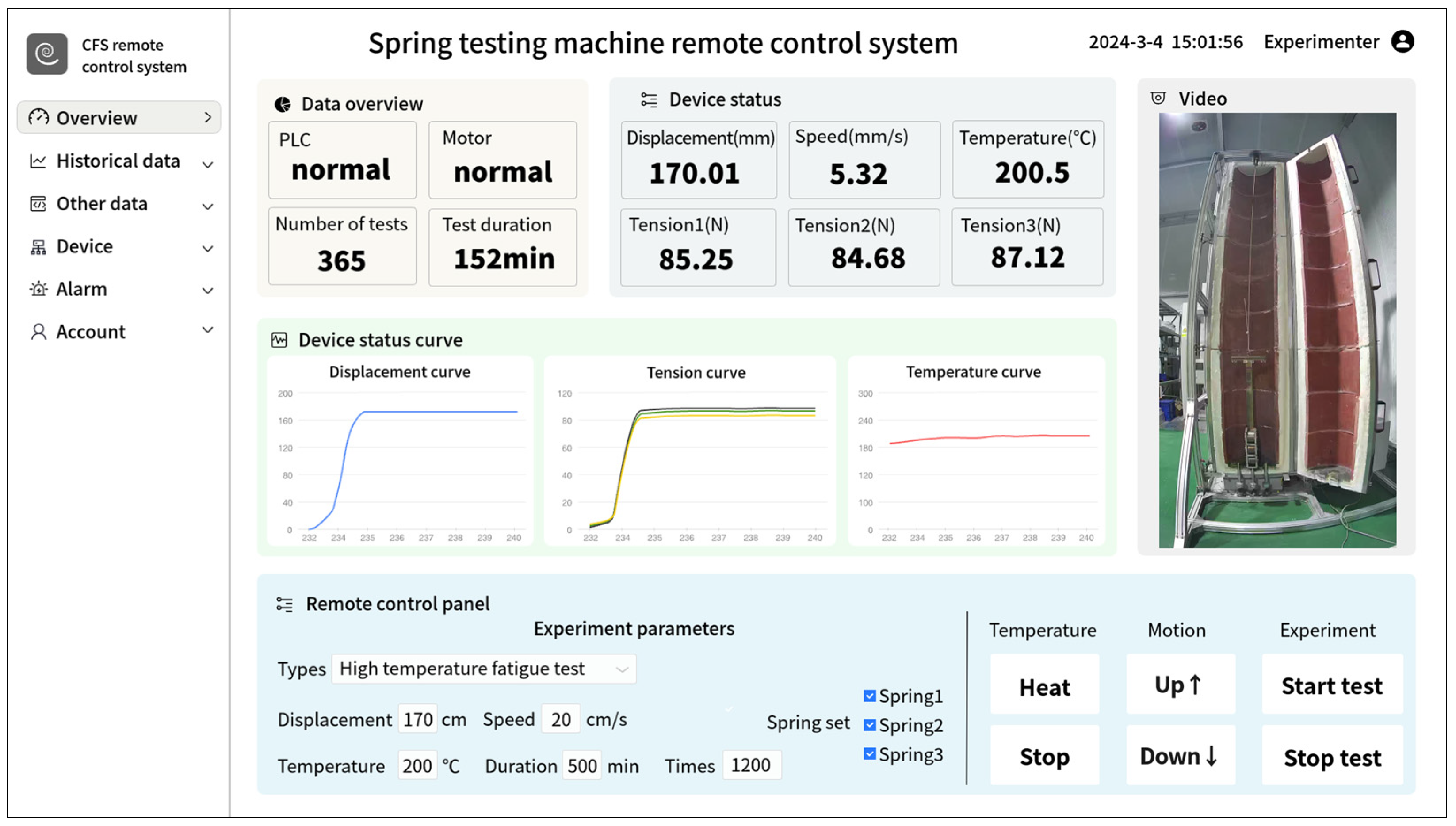
The user interface layer is used to realize user data interaction on the browser side, including displaying dynamic data information transmitted by the business logic layer in a reasonable form, and transmitting user-input data to the business logic layer, and this layer is mainly implemented through HTML, CSS, and JavaScript technologies and the website index page is shown in Figure 6; the business logic layer is the middle layer of the entire architecture, processing and transmitting data according to the actual needs of the user interface layer and data access layer; the data access layer is used to provide original data services for the business logic layer and user interface layer, and this layer is connected to the database service on the cloud server, including addition, deletion, modification and query of the database.

5. Experimental Results

The experimental verification of the remote monitoring and control system was carried out based on the high-temperature constant-force spring fatigue testing machine. The hardware configuration of the host computer, Alibaba Cloud server, and client computer is shown in Table 2 below. The remote host computer collects RTMP video streams through a Hikvision camera (DS-IPC-T13HV3-IA), which from Hangzhou Hikvision Digital Technology Co., Ltd., Hangzhou, China. The video is encoded in H.265 format. The video frame rate is 25 p and the video bit rate is 100 kb/s.

5.1. System Function Verification

The mechanical structure of the spring fatigue testing machine is working normally, and the fatigue test has been carried out normally. The host computer software communicates normally with the PLC, the surveillance camera works normally, and the host computer can collect sensor data in real time and upload them to the cloud server.
The cloud server database backup is normal, WebSocket communication is normal, and video surveillance streaming is normal.
The web client can log in to the website normally; the WebSocket communication is normal, and the status parameters of the remote testing machine can be obtained in real time; the historical experimental data can be read normally; and the remote video monitoring screen can be obtained.

5.2. Network Communication Test

In order to test the network communication quality of the remote monitoring and control system, we tested the delays of WebSocket communication and video surveillance at different time points, as shown in Table 3 below. The communication delay from the web end to the remote machine end is t1, the communication delay from the remote machine end to the web end is t2, and the video surveillance delay is t3. We calculated the average end-to-end delay by averaging collections multiple collections at 0:00, 5:00, 10:00, 13:00, 17:00, and 21:00.
Through actual testing, it was found that the delay of WebSocket two-way real-time communication is very low, only about 11 ms, and the communication delay from the web side to the machine side will be slightly lower than the direction from the machine side to the web side. It should be noted that the delay here is only the difference between the sending time and the receiving time, and does not include the respective processing time of both ends. Since the amount of video monitoring data is much larger than that of WebSocket communication, and there is video encoding and decoding, the delay was 291 ms, which can still meet the real-time monitoring requirements of remote experiments.

6. Conclusions

Traditional reliability testing experimental machines have low automation, poor experimental environment, and require more labor costs to complete the experiment. The remote monitoring and control system based on cloud technology proposed in this paper has greatly improved the automation of these machines. Experimenters can remotely control experimental equipment through the public network in a better office environment. It makes up for the shortcomings of traditional detection and solves the difficulties and pain points of traditional fatigue detection.
Through experimental verification, the cloud-based spring fatigue testing machine remote monitoring and control system proposed in this paper achieves end-to-end remote real-time communication across the local area network. The WebSocket-based communication solution has a delay of only 11 ms, and the RTMP-based video monitoring delay is only 291 ms. The system shows good performance and high stability. It can well meet the needs of remote real-time control.
There is only one machine being monitored and controlled in this system. In the future, more testing machines can be incorporated into the cloud monitoring and control system to build an automated and intelligent testing model and build an intelligent testing laboratory. Since the springs to be tested are characterized by small batches and diversification, manual loading and unloading and replacement of tooling fixtures are currently required. In the future, an automated loading and unloading mechanism will be designed to automate the entire testing process and enable unmanned testing of the experiment.
In the future, artificial intelligence algorithms can be integrated into cloud service systems to achieve intelligent data analysis and fault prediction. At the same time, the security performance of the system will also be upgraded to provide more secure and reliable remote monitoring and control services.
This paper is an exploration of remote monitoring and control technology in reliability testing machines. The research in this paper provides a new technical path and theoretical support for the development of remote real-time monitoring and control technology. The technology in the paper can be easily copied and expanded, and has a certain reference and reference role for similar industrial applications.

Author Contributions

Conceptualization and methodology, G.W. and D.W.; software and validation, G.W.; formal analysis, investigation, resources, and data curation, T.X. and P.C.; writing—original draft preparation and writing—review and editing, G.W.; visualization, C.S.; supervision, T.X. and P.C.; project administration and funding acquisition, F.F. and P.Z. All authors have read and agreed to the published version of the manuscript.

Funding

This research was funded by the National Key Research and Development Plan: Research Project on Basic General International Standards for Equipment Manufacturing, grant number 2021YFF0601702.

Data Availability Statement

The original contributions presented in the study are included in the paper material, and the data and code of the core are available from the corresponding author upon reasonable request.

Acknowledgments

The authors thank the China Productivity Center for Machinery for their financial support and would like to thank the editors and anonymous reviewers for their valuable comments and suggestions.

Conflicts of Interest

Tonghui Xu was employed by the company China Nuclear Power Engineering Co., Ltd. The remaining authors declare that the research was conducted in the absence of any commercial or financial relationships that could be construed as a potential conflict of interest.

References

  1. Ikechukwu, G.A.; Clementina, O.O.; Onyebuchi, C.L. Design and characterization of a fatigue testing machine. In Proceedings of the World Congress on Engineering and Computer Science, San Francisco, CA, USA, 23–25 October 2013. [Google Scholar]
  2. Asyrafa, M.; Ishaka, M.; Razmand, M.; Chandrasekara, M. Fundamentals of creep, testing methods and development of test rig for the full-scale crossarm: A review. Stress 2019, 36, 38. [Google Scholar] [CrossRef]
  3. Hieu, T.V.; Hong, N.T. Mechanical Engineering Excellence: Design and Optimization of Two-Dimensional Fatigue Testing Machines. Q. J. Emerg. Technol. Innov. 2024, 9, 1–14. [Google Scholar]
  4. Lu, P.; Jia, P. Compression Spring Fatigue Tester Design and Development. J. Adv. Artif. Life Robot. 2022, 3, 56–60. [Google Scholar]
  5. Xu, X. From cloud computing to cloud manufacturing. Robot. Comput.-Integr. Manuf. 2012, 28, 75–86. [Google Scholar] [CrossRef]
  6. Wan, J.; Yang, J.; Wang, Z.; Hua, Q. Artificial intelligence for cloud-assisted smart factory. IEEE Access 2018, 6, 55419–55430. [Google Scholar] [CrossRef]
  7. Qu, X.; Wang, H. Emergency task offloading strategy based on cloud-edge-end collaboration for smart factories. Comput. Netw. 2023, 234, 109915. [Google Scholar] [CrossRef]
  8. Gharibvand, V.; Kolamroudi, M.K.; Zeeshan, Q.; Çınar, Z.M.; Sahmani, S.; Asmael, M.; Safaei, B. Cloud based manufacturing: A review of recent developments in architectures, technologies, infrastructures, platforms and associated challenges. Int. J. Adv. Manuf. Technol. 2024, 131, 93–123. [Google Scholar] [CrossRef]
  9. Bacci di Capaci, R.; Scali, C. A cloud-based monitoring system for performance assessment of industrial plants. Ind. Eng. Chem. Res. 2020, 59, 2341–2352. [Google Scholar] [CrossRef]
  10. Touhid, M.T.B.; Marne, M.; Oskroba, T.; Mirahmadi, S.A.; Zhu, E.; Mehrabian, A.; Defersha, F.; Yang, S. Building a cloud-based digital twin for remote monitoring and control of a robotic assembly system. Int. J. Adv. Manuf. Technol. 2023, 129, 4045–4057. [Google Scholar] [CrossRef]
  11. Liu, C.; Jiang, P.; Jiang, W. Web-based digital twin modeling and remote control of cyber-physical production systems. Robot. Comput.-Integr. Manuf. 2020, 64, 101956. [Google Scholar] [CrossRef]
  12. Stefanuto, B.; Piardi, L.; Junior, A.O.; Vallim, M.; Leitão, P. Remote Lab of Robotic Manipulators through an Open Access ROS-based Platform. In Proceedings of the 2023 IEEE 21st International Conference on Industrial Informatics (INDIN), Lemgo, Germany, 18–20 July 2023; pp. 1–6. [Google Scholar]
  13. Vanegas-Guillén, O.; Parra-Rosero, P.; Muñoz-Antón, J.M.; Zumba-Gamboa, J.; Dillon, C. Remote Labs Meet Computational Notebooks: An Architecture for Simplifying the Workflow of Remote Educational Experiments. IEEE Access 2023, 11, 132496–132515. [Google Scholar] [CrossRef]
  14. Viswanadh, K.; Gureja, A.; Walchatwar, N.; Agrawal, R.; Sinha, S.; Chaudhari, S.; Vaidhyanathan, K.; Choppella, V.; Bhimalapuram, P.; Kandath, H. Engineering End-to-End Remote Labs using IoT-based Retrofitting. arXiv 2024, arXiv:2402.05466. [Google Scholar]
  15. Feng, M. Research and Application of Remote Monitoring System for Creep Test Machine Based on ARM. Master’s Thesis, Northern University for Nationalities, Ningxia, China, 2019. (In Chinese). [Google Scholar]
  16. Xu, A. Multi-physical Quantity Remote Measurement and Control Simulation Test System for Machine Tools. Master’s Thesis, Anhui University of Science and Technology, Huainan, China, 2022. (In Chinese). [Google Scholar]
  17. Yang, H.; Yang, J.; Huang, H.; Shi, Y.; Peng, D. Development and application of remote test network monitoring system. Automot. Technol. 2022, 3, 44–50. (In Chinese) [Google Scholar] [CrossRef]
  18. Qi, H.; Zhao, J.; Sun, L.; Cang, T.; Li, Y.; Wang, X. Design of a multi-channel fatigue test monitoring cloud platform based on the Internet of Things. In Proceedings of the 2022 6th International Symposium on Computer Science and Intelligent Control (ISCSIC), Beijing, China, 11–13 November 2022; pp. 112–117. [Google Scholar]
  19. Bartoň, M.; Budjač, R.; Tanuška, P.; Schreiber, P.; Horák, T. Industry Communication Based on TCP/IP Protocol. Res. Pap. Fac. Mater. Sci. Technol. Slovak Univ. Technol. 2021, 29, 59–66. [Google Scholar] [CrossRef]
  20. Manvi, S.S.; Shyam, G.K. Resource management for Infrastructure as a Service (IaaS) in cloud computing: A survey. J. Netw. Comput. Appl. 2014, 41, 424–440. [Google Scholar] [CrossRef]
  21. Zhang, Y.; Pan, F. Design and implementation of a new intelligent warehouse management system based on MySQL database technology. Informatica 2022, 46, 355–364. [Google Scholar] [CrossRef]
  22. Pimentel, V.; Nickerson, B.G. Communicating and displaying real-time data with websocket. IEEE Internet Comput. 2012, 16, 45–53. [Google Scholar] [CrossRef]
  23. Puranik, D.G.; Feiock, D.C.; Hill, J.H. Real-time monitoring using AJAX and WebSockets. In Proceedings of the 2013 20th IEEE International Conference and Workshops on Engineering of Computer Based Systems (ECBS), Scottsdale, AZ, USA, 22–24 April 2013; pp. 110–118. [Google Scholar]
  24. Bozdag, E.; Mesbah, A.; Van Deursen, A. A comparison of push and pull techniques for ajax. In Proceedings of the 2007 9th IEEE International Workshop on web site evolution, Paris, France, 5–6 October 2007; pp. 15–22. [Google Scholar]
  25. Fecheyr-Lippens, A. A review of http live streaming. Internet Cit. 2010, 1–37. Available online: https://issuu.com/andruby/docs/http_live_streaming (accessed on 27 June 2020).
  26. Murley, P.; Ma, Z.; Mason, J.; Bailey, M.; Kharraz, A. Websocket adoption and the landscape of the real-time web. In Proceedings of the Proceedings of the Web Conference, Ljubljana, Slovenia, 19–23 April 2021; pp. 1192–1203. [Google Scholar]
  27. Chen, K.-B.; Chang, H.-Y. Complexity of cloud-based transcoding platform for scalable and effective video streaming services. Multimed. Tools Appl. 2017, 76, 19557–19574. [Google Scholar] [CrossRef]
Figure 1. Remote monitoring and control system architecture.
Machines 12 00462 g001
Figure 2. Structural diagram of the constant-force spring fatigue testing machine (1 testing machine bracket, 2 tubular heating furnace, 3 constant-force spring, 4 motion module, 5 tension and pressure sensor, 6 spring clamp).
Machines 12 00462 g002
Figure 3. Spring fatigue testing machine control system.
Machines 12 00462 g003
Figure 4. Host computer software interface.
Machines 12 00462 g004
Figure 5. Cloud server structure.
Machines 12 00462 g005
Figure 6. Website index page.
Machines 12 00462 g006
Table 1. Regional node delay test.
Regional NodeCityIP AddressDelay
North China 2Beijing59.110.190.697 ms
East China 2Shanghai106.14.228.19429 ms
China Hong KongHong Kong (China)120.77.166.22649 ms
South China 1Shenzhen47.75.18.1349 ms
Asia Pacific Northeast 1Tokyo47.91.8.4275 ms
Middle East 1Dubai47.91.99.127354 ms
Southeast Asia 1Singapore47.74.196.4083 ms
BritainLondon8.208.40.20172 ms
Western America 1Silicon Valley47.88.73.1204 ms
Table 2. Hardware configuration.
Client ComputerCloud ServerHost Computer
Operating systemWindows 11 x64Windows Server 2022 x64Windows 11 x64
ProcessorAMD Ryzen 7 5700X
8-Core 3.4 GHz
Intel Xeon Platinum
2-core 2.5 GHz
Intel i5-8265U
4-core 1.6 GHz
Memory16 G4 G8 G
Bandwidth1000 Mbps100 Mbps1000 Mbps
Table 3. Communication delay test.
Timet1/mst2/mst2/ms
0:001011280
5:001010265
10:001111287
13:001112306
17:001213312
21:001111296
average10.811.3291.0
Disclaimer/Publisher’s Note: The statements, opinions and data contained in all publications are solely those of the individual author(s) and contributor(s) and not of MDPI and/or the editor(s). MDPI and/or the editor(s) disclaim responsibility for any injury to people or property resulting from any ideas, methods, instructions or products referred to in the content.