1. Introduction
Cross-flow fans (CFFs) installed in the semiconductor industry are exposed to harsh environmental conditions due to toxic and corrosive gases and are subject to stringent standards. No wear, friction or contamination, and a rotor inside a hermetically sealed process chamber are crucial and lead to the highest performance requirements for the implemented drives. Bearingless motors enable wear-free, practically maintenance-free, and continuous operation of CFFs under these extreme conditions. In [
1], the authors presented the bearingless high-speed CFF for applications in deep ultraviolet (DUV) excimer laser, which are commonly used as the light source in industrial lithography systems [
2]. The fluid dynamic performance of the CFF is an important factor that limits the gas exchange rate of the lasers in a given, constrained installation space of complex manufacturing devices. Increasing the CFF rotational speed and therefore the fluid performance is a key enabler for improving the laser performance, the scanning speed of lithography systems, and finally, the chip throughput [
3,
4,
5,
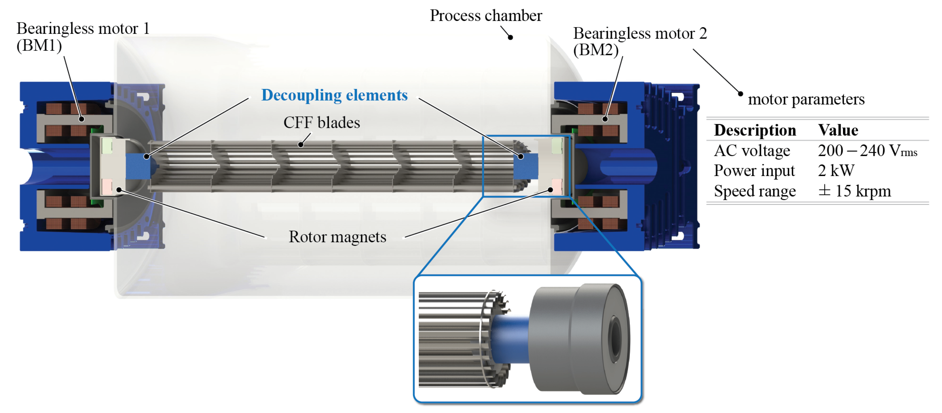
6]. The maximum achievable rotational speed of current bearingless CFFs is restricted by the plastic deformation of the CFF rotor at the critical bending resonance frequency. The operation is therefore limited to subcritical speeds. This paper presents a bearingless CFF rotor, which is operated supercritically to increase the fluid dynamic performance. The CFF rotor features additional mechanical elements with low stiffness (hereafter referred to as “decoupling elements”), which connect the rotor magnets and the CFF blades according to
Figure 1. The influence of the decoupling elements on the rotor dynamic behaviour (vibration modes) is examined by a mass-spring-damper model and the influence on the magnetic bearing is tested with different prototypes. Additionally, the effects on the CFF’s fluid dynamic performance are evaluated.
CFF rotors have a distinctive large length-to-diameter ratio and consist of several thin blades arranged in a circular manner to achieve the optimal fluid dynamic performance [
7,
8,
9]. The long and thin blades result in a low mechanical bending stiffness. Consequently, the CFF rotor plastically deforms under the unbalance forces, which increase quadratically with the rotational speed, at the critical bending resonance frequency. The use of magnetic bearings amplifies this problem due to the rotor magnets on both ends of the CFF rotor, which add significant mass but minimal contribution to the overall rotor bending stiffness. The CFF rotor presented in [
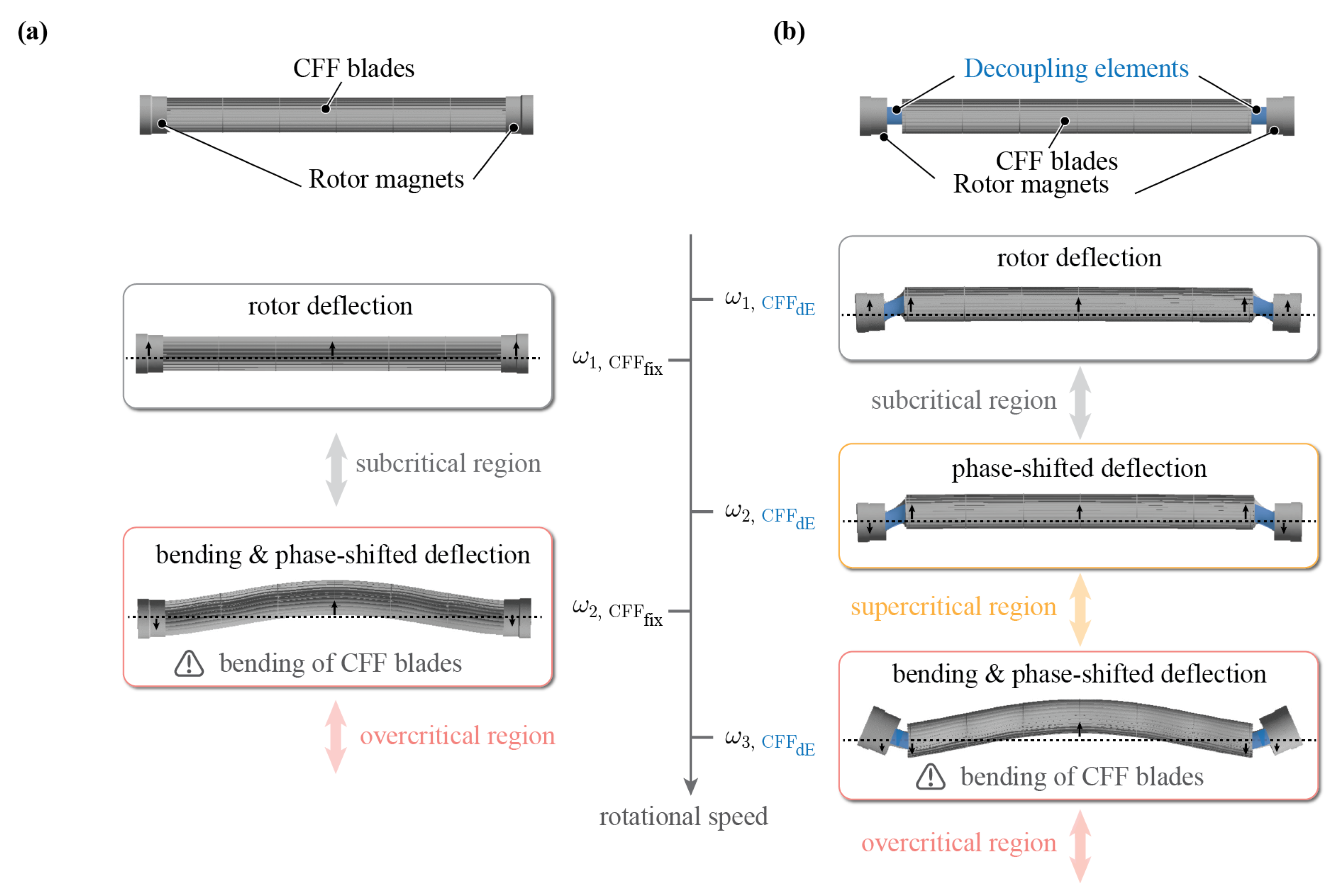
1] consists of two rotor magnets, which are rigidly mounted to the CFF blades as depicted in
Figure 2a. The maximum achievable speed is limited by the bending resonance frequency. The low bending stiffness of the CFF blades causes plastic deformation of the blades near the bending resonance frequency, which prevents its surpassing, as shown in
Figure 2a with
. Thus, the CFF is limited to subcritical operation.
In the literature, different control approaches for the active magnetic bearing system to dampen, pass or eliminate resonance frequencies are proposed [
10,
11,
12,
13,
14,
15,
16,
17,
18,
19,
20,
21,
22,
23]. Complex position control methods are presented to pass the bending resonance frequency of a flexible test rotor. However, these methods consider massive shafts and Jeffcott rotors with mass distributions and bending stiffnesses that are not comparable to the CFF rotor, of which the mechanical design is restricted by the fluid dynamical requirements. Therefore, the proposed control algorithms are not directly applicable to the problem at hand.
In this paper, however, a rotor design approach is explored to shift the CFF’s critical resonance frequencies and rotor bending to higher rotational speeds. Additional mechanical elements with a low stiffness decouple the CFF blades from the rotor magnets. The vibration behaviour is influenced such that an additional, third resonance frequency occurs as visualised in
Figure 2b. The decoupling elements are deformed under the unbalance forces at the first two resonance frequencies
and
, which results in a deflection and small, non-plastic deformation of the CFF blades. The two-mode shapes differ in the phase shift between rotor magnets and the CFF rotor. The region above the first two resonance frequencies is referred to as the supercritical region since the CFF rotor centres itself with respect to the rotational axis [
24,
25]. The third resonance frequency,
, is characterised by the detrimental bending of the CFF blades, similar to the second resonance frequency of the non-decoupled CFF, which again leads to plastic deformation of the CFF blades. However,
is shifted to higher frequencies than
of the non-decoupled rotor. Hence, the new rotational speed limit can be increased.
The design of the multi-component rotor is critical. The decoupling elements must have a low enough mechanical stiffness to enable effective mechanical decoupling and therefore prevent the bending of the blades. But the stiffness cannot be too low such that the fluid dynamic forces acting on the rotor lead to high deflections and instabilities. Furthermore, the magnetic bearing must be able to withstand the forces that result from passing through the resonance frequencies and .
This paper aims to address these challenges by first modelling the bearingless CFF rotor with a mass-spring-damper model in
Section 2, to analyse the influence of the introduced decoupling element. Various decoupling elements are then experimentally tested, to evaluate their influence on the magnetic bearing and compared with the mass-spring-damper model in
Section 3. Finally, the fluid dynamic performance of the CFF rotor with the optimal decoupling element is investigated in
Section 4.
2. Modelling of CFF Resonance Frequencies
The goal of this section is to gain an understanding of the vibration modes of bearingless CFF rotors with and without decoupling elements by means of a mass-spring-damper (mkd)-model.The focus lies on the comparison of the resonance frequencies and mode shapes of CFF rotors with rigidly mounted rotor magnets to the newly introduced, decoupled rotors, particularly to investigate the modes associated with the bending of the CFF blades, since these are speed and performance-limiting. The influence of the decoupling element stiffness is investigated and the effect of shifting the critical bending resonance frequency to higher frequencies explained.
2.1. mkd-Model of Bearingless CFF Rotor
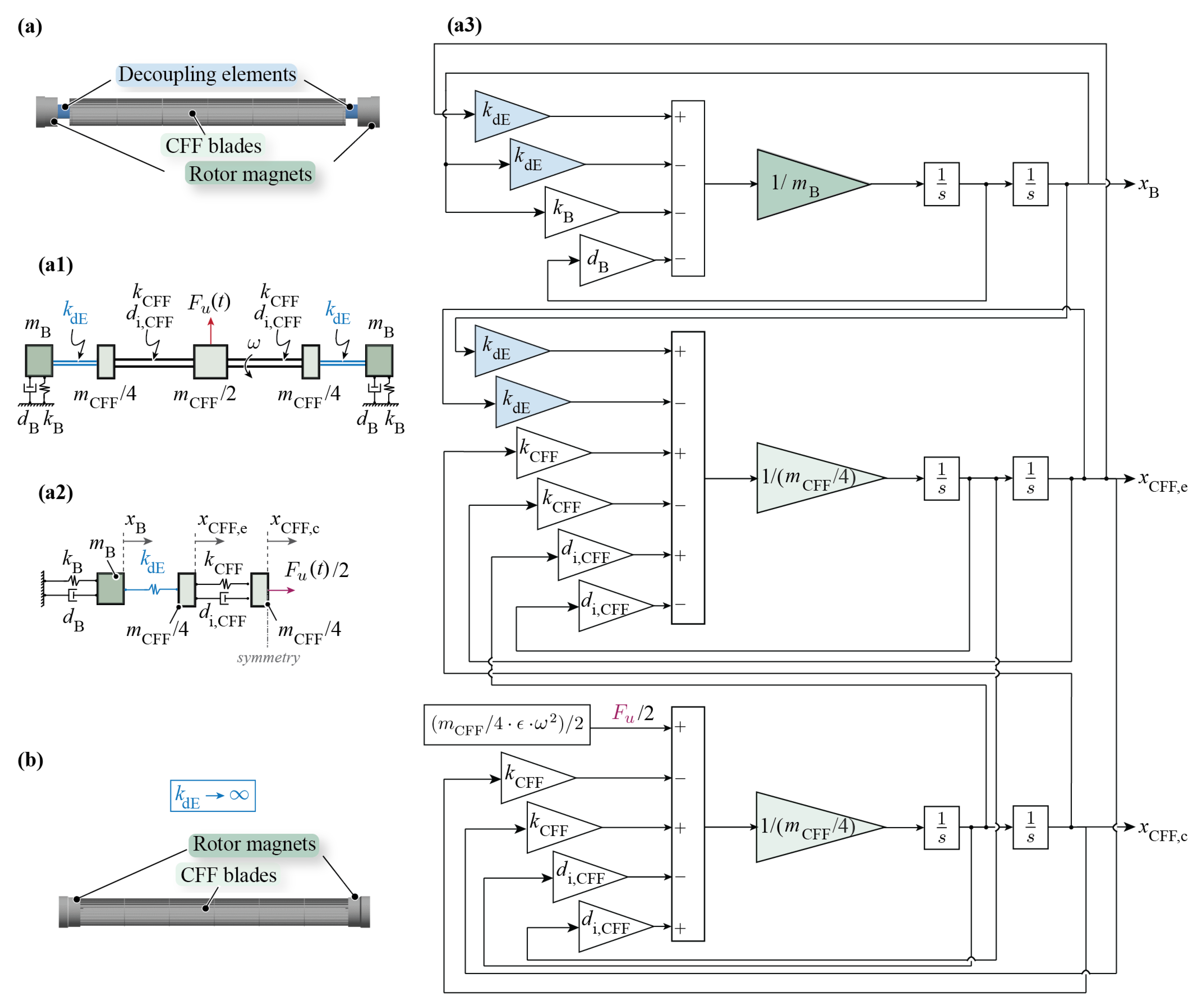
The bearingless CFF rotor is modelled using
mkd-elements as shown in
Figure 3. The rotor is assumed symmetrical; thus, only symmetrical vibration modes are studied. The rotor magnets with mass
are coupled to the fixed reference frame via the magnetic bearing, which is modelled by the stiffness
and damping value
. The parameters
and
can be influenced by the PD position control parameters of the magnetic bearing according to
and
where
P is the position-proportional and
D the velocity-proportional feedback element of the PD control,
the force/current and
the force/displacement constant of the drive [
25]. The CFF blades are represented in a simplified manner with a measured mass
, bending stiffness
and internal damping
, while
. The mass of the CFF blades is modelled using three mass elements to represent the connection between the rotor magnets and blades as well as to clearly characterise vibration modes leading to rotor bending. The decoupling element, connecting the rotor magnets and CFF blades, is modelled as a spring with stiffness
. Its mass and internal damping are assumed to be negligible. The systems’ mass unbalance is modelled such that it is concentrated in the CFF centre mass element and that it is created by the small offset
. It denotes the offset of the mass centre from the axis of rotation, which only influences the resonance amplitude and is set to a finite small value for this analysis.
Thus, the following equations of motion are obtained for the modelled CFF system
This results in the unbalance force excitation
with
being the mass eccentricity rotating at frequency
[
26,
27,
28,
29,
30,
31,
32]. The mass matrix
is defined as
the damping matrix
as
and stiffness matrix
as
To simulate the CFF rotor with rigidly mounted rotor magnets, the spring constant of the decoupling element can be set to . Alternatively, for a decoupled CFF rotor, is set to a finite, variable value. An unbalance force is then applied and the following amplitudes are evaluated: magnetic bearing deflection , the CFF blades’ edge deflection and CFF blades’ centre deflection .
2.2. Unbalance Response of CFF with Rigidly Mounted Rotor Magnets
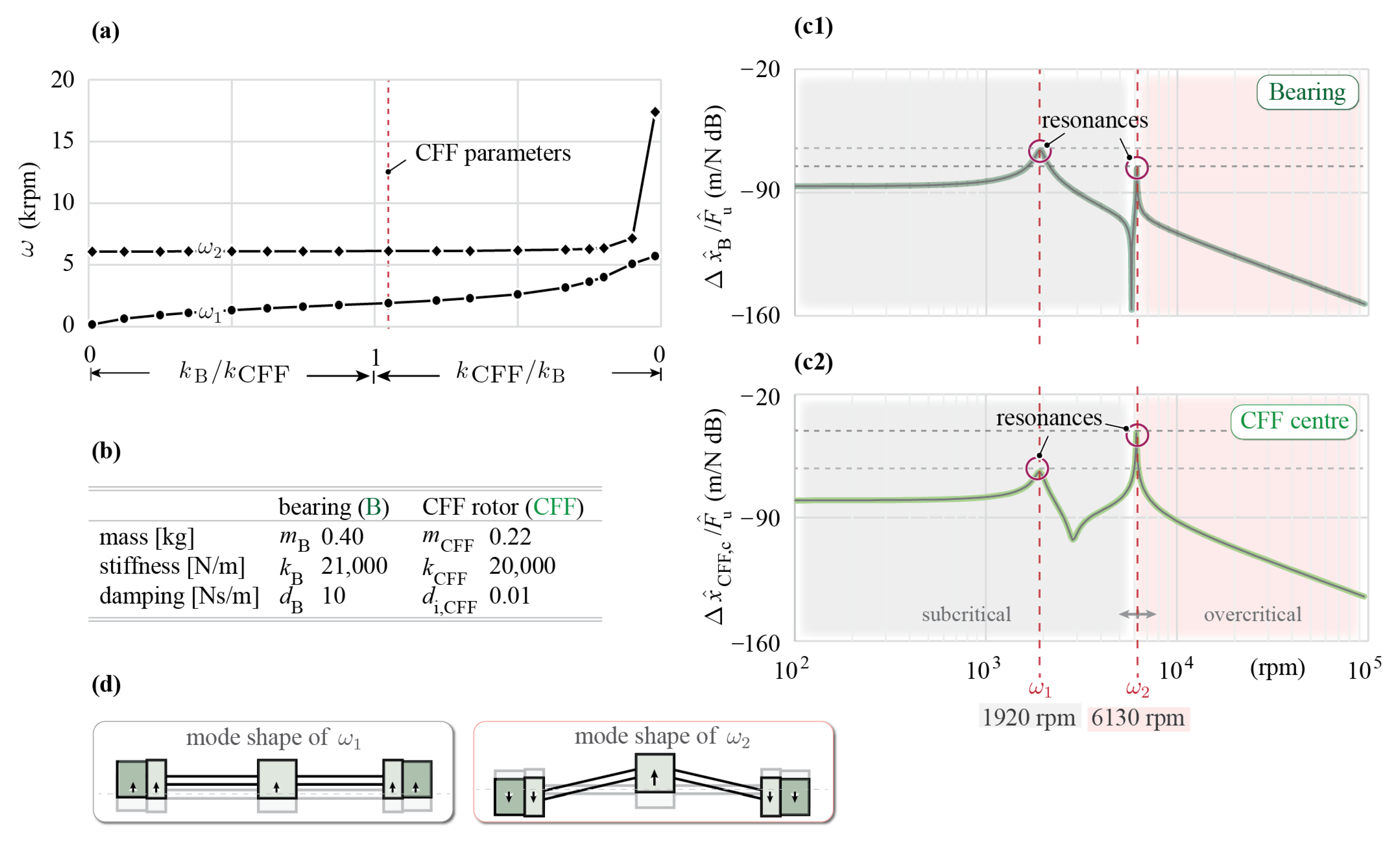
The simulated resonance frequencies are evaluated with respect to the ratio between the magnetic bearing stiffness
and CFF blades stiffness
and the results shown in
Figure 4a. In general, the case
represents a free-free supported rotor (
), with
being the rigid body mode frequency that approaches 0 and
the free-free resonating rotor, i.e., the bending resonance frequency. For the other extreme edge case of
the bearing is assumed to be rigid (
). The bending resonance frequency corresponds to
while
represents the resonance of the rotor magnet masses
on the magnetic bearing, which is virtually uninfluenced by the blades’ stiffness
.
The parameters of the rigid CFF rotor listed in
Figure 4b are applied to the
mkd-model, resulting in the rigid body mode at
and the bending resonance mode at
.
The mode shape of
is illustrated in
Figure 4d, which represents the resonance frequency of the magnetic bearing, i.e., the rigid body mode, where the rotor would deflect from its rotational axis without bending. The rigid body mode does not pose a problem for the operation of the CFF due to the implementation of a force-rejection algorithm in the position controller of the drive, which prevents the unbalance force from exciting this mode [
1].
The mode shape of depicts the bending of the CFF blades. The CFF blades with heavy rotor magnets mounted on each end can lead to displacements big enough to cause plastic deformation of the CFF blades. This results in permanent damage of the rotor, which strictly limits the directly coupled CFF rotor to subcritical use below .
2.3. Unbalance Response of CFF with Decoupled Rotor Magnets
For the CFF rotor with mechanically decoupled rotor magnets, the resonance frequencies are evaluated depending on the ratio between the decoupling element stiffness
and CFF blades stiffness
. For the simulation, the magnetic bearing stiffness
, which according to Equation (
1) depends on the force/current and force/displacement constants, defined by the motor topology, and the variable position control parameter
P, is set to a fixed value, which results in stable motor operation.
The system response is shown in
Figure 5a and the measured CFF rotor parameters are listed in
Figure 5b. The stiffness ratio
represents the case
, which is again the rigidly mounted CFF rotor with
rpm,
rpm and
from
Section 2.2.
To simulate the decoupling between CFF blades and rotor magnets, the stiffness ratio of
is applied to the
mkd-model. The amplitude and phase of deflection of an unbalance excitation to this system are then evaluated at the magnetic bearing
, the CFF blades edge
as well as centre
and result in mode shapes of
Figure 5d.
The simulation results reveal, that the resonance frequencies of
rpm and
rpm shift downwards, compared to the resonance frequencies from the CFF rotor from
Section 2.2.
At , the rotor magnets and CFF blades deflect (in phase) from their initial position, whereby the CFF blades remain almost undeformed throughout their length. The mode shape of differs in the phase-shift between the deflection of the rotor magnets and CFF blades. At these rotational speeds, the unbalance forces cause high elastic deformation of the decoupling elements and much lower elastic deformation of the CFF blades, since the decoupling elements possess a lower mechanical stiffness (). Hence, the critical resonance frequencies and can be passed. The speed range above these frequencies is considered supercritical, since the CFF rotor self-centres and allows a stable operation up to the third resonance frequency.
The third resonance frequency occurs at 8700 rpm and is associated with the detrimental bending of the CFF blades. It is mainly driven by the stiffness , which cannot be further modified than what the fluid dynamic design requirements to the blade geometry allow for. Since plastic deformation only occurs when approaching , the new speed limit is therefore increased by 42% compared to of the rotor with rigidly mounted rotor magnets.
3. Experimental Investigation of Decoupling Elements
The experimental investigation is conducted for different decoupling elements between the CFF blades and the rotor magnets, to examine their influence on the magnetic bearing, which can only compensate for forces and allow displacements to a limited extent. The aim is to determine with which decoupling element the rotor can be operated at the highest rotational speeds. Moreover, the performed rotor dynamic measurements are compared with the simulation results. These measurements are conducted without the influence of any fluid dynamic loads; therefore, the CFF blades are covered. The rotor magnet displacements in the magnetic bearing are measured using built-in sensors in the bearingless motor 1 (BM1) and 2 (BM2). For the CFF blade displacements and , laser-based distance sensors S1, S2, and S3 are employed to verify the expected mode shapes.
3.1. Influence of the Decoupling Elements on Resonance Frequencies
Seven different decoupling elements are characterised and tested, which leads to the parameters and measured resonance frequencies summarised in
Table 1. The respective bending stiffnesses
are determined by a force-displacement measurement. All decoupling elements consist of the same rubber material and solely vary in their diameter and length.
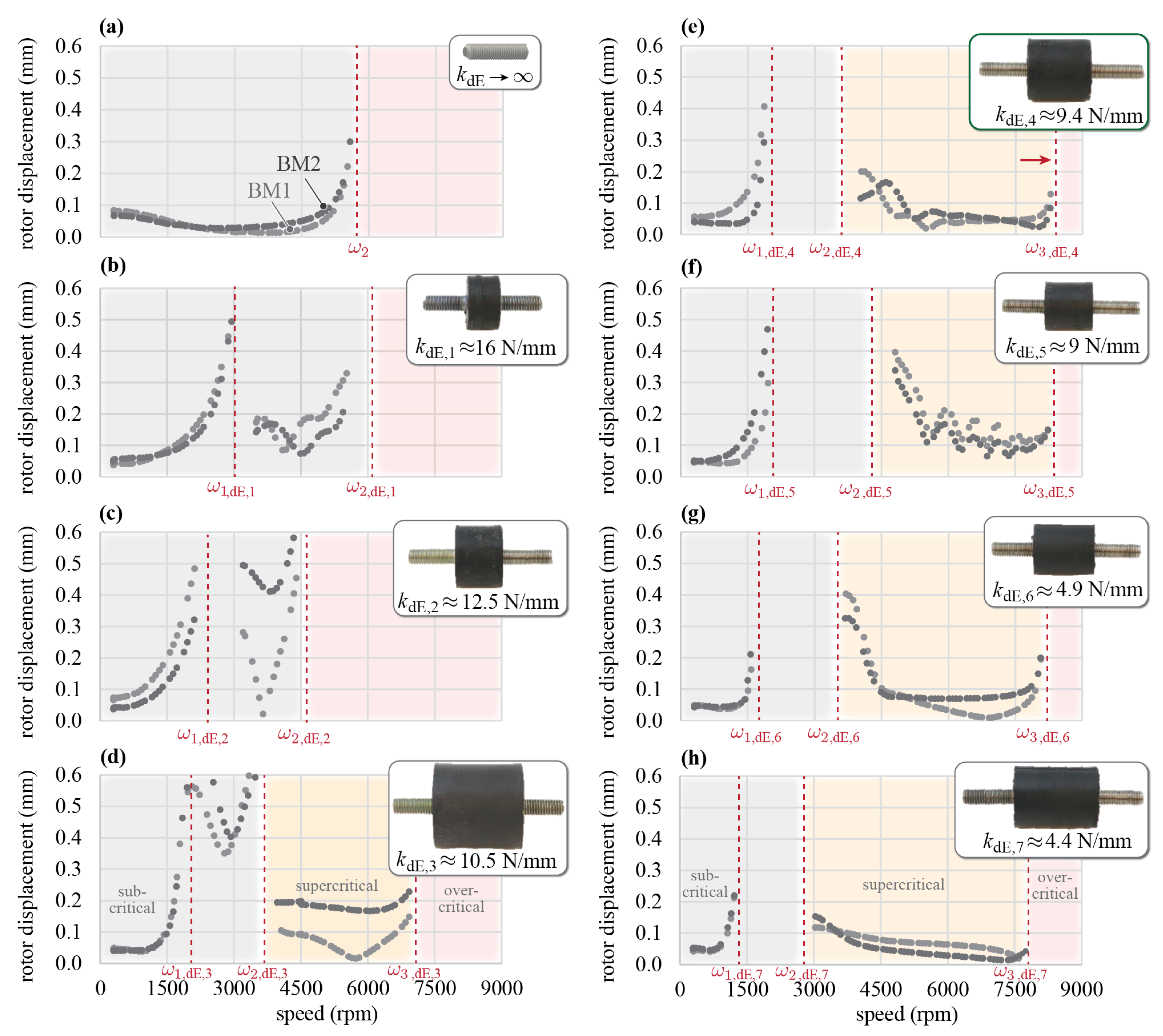
The measured radial rotor displacements in the magnetic bearing for the CFF with rigidly mounted rotor magnets are shown in
Figure 6a and serve as a reference measurement. The rigid body mode does not pose a problem for the magnetic bearing. However, a rapidly increasing radial displacement is measured for BM1 and BM2 when approaching the bending resonance frequency. The unbalance forces lead to a plastic deformation of the CFF blades, therefore it is not possible to pass approximately 5800 rpm.
The rotor dynamic measurements are performed for seven decoupled CFF rotors (
Figure 6b–h). Auxiliary touch-down bearings prevent a possible collision between the CFF blades and the static CFF casing walls when passing the first two resonance frequencies.
The aim is to find the decoupling element with the best trade-off between a low enough stiffness , such that the CFF blades do not plastically bend at the second resonance frequency, but a high enough stiffness to shift to higher frequencies. Additionally, the mass of the decoupling element should be low to prevent extra mass in the rotor, which leads to a reduction in . Furthermore, a high enough is required for the rotor to withstand the fluid dynamic forces created by the CFF blades.
The results from
Figure 6b,c show that with decoupling elements
and
the target of supercritical operation is not achieved, because their stiffnesses
and
are too high. The magnetic bearing is not able to compensate for the forces when approaching the resonance frequencies
and
.
The remaining decoupling elements are successfully operated in the supercritical speed region (
Figure 6d–h). It can be seen that decoupling element
has the lowest resonance frequency
; therefore, it reached the lowest maximum speed. This can be justified by its large mass, which is almost 40% higher compared to the second heaviest supercritically operated element.
The measurements further show that decoupling element reaches the highest rotational speed. It offers the best trade-off between a low enough stiffness to successfully operate in the supercritical region, and at the same time a high enough stiffness and low mass , which leads to the highest frequency of in this study.
3.2. Influence of Decoupling Elements on Mode Shapes
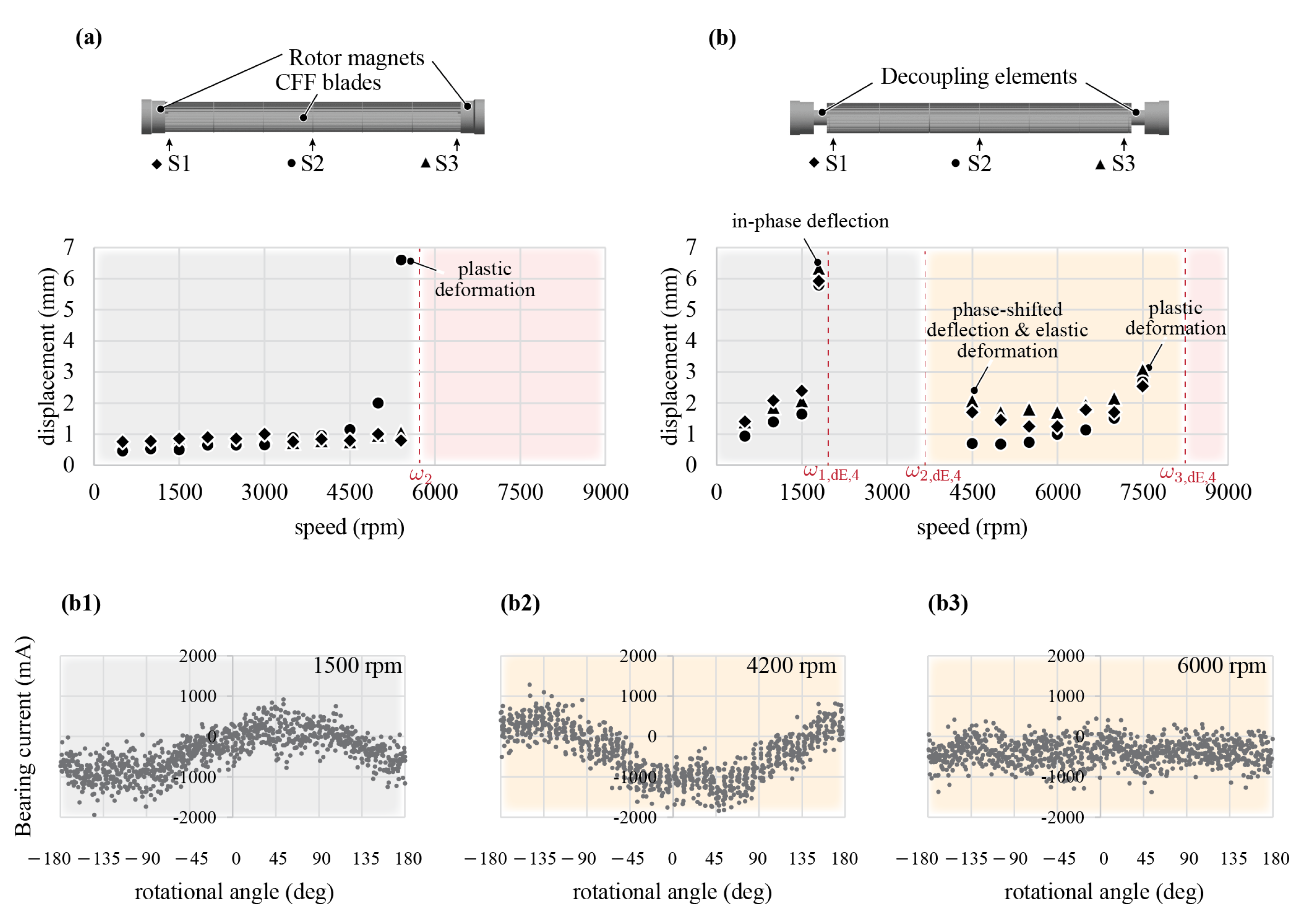
The different mode shapes and the supercritical self-centring effect of the decoupled CFFs are further verified with laser distance measurements on the CFF blades, which are summarised in
Figure 7. The results of the CFF with rigidly mounted rotor magnets confirm that the CFF blades start to bend with increasing speed. In the vicinity of the bending resonance frequency, the low bending stiffness of the CFF blades allows the unbalance forces to cause plastic deformation of the blades up to 6 mm (see
Figure 7a), thus preventing the passing of the resonance frequency.
The displacements of the CFF rotor with decoupling element
are measured with the same sensor setup at different rotational speeds. The CFF blades deflect in-phase and out-of-phase with respect to the rotor magnets close to the first and second resonance frequencies, respectively. Additionally, an elastic deformation is measured after the second resonance is passed. The plastic deformation of the CFF blades occurs towards the third resonance frequency
(see
Figure 7(b1)).
Furthermore, the bearing currents are evaluated at subcritical speeds of 1500 rpm (close to
), at 4200 rpm (shortly after
) and at 6000 rpm (supercritical operation) as seen in
Figure 7(b2). The phase shift of 180° between the bearing currents at 1500 rpm and 4200 rpm demonstrates that the force on the magnetic bearing acts in opposing directions. This confirms the phase-shifted deflections of mode shapes
and
. From the bearing current at 6000 rpm, a stable supercritical speed operation is detected, clearly showing the self-centring effect of the rotor from
onwards.
3.3. Comparison and Verification of the mkd-Model
The measured resonance frequencies of the rotors fitted with decoupling elements
to
are plotted on the simulation results from
Section 2.3 with respect to the stiffness ratio of the decoupling element stiffness and the CFF bending stiffness (
) in
Figure 8a. To eliminate the effect of the decoupling element’s mass, which has been neglected in the
mkd-model, the measured resonance frequencies are plotted with respect to the mass-compensated stiffness ratio
in
Figure 8b. Comparing the experimental data with the simulation results, it can be seen that the resonance frequencies
,
and
increase with increasing decoupling element stiffness
for both the experimental data and the simulation results. The resonance frequency
features the lowest slope. The mass compensation method leads to a better fit between the theory and measurements according to
Figure 8b. The deviation between simulated and measured resonance frequencies is explained by the approximated model parameters, e.g., the stiffness values have been measured by simplified force-displacement measurements. Additionally, the measured resonance frequencies have to be estimated in their vicinity, since the rotor cannot be operated in the resonance itself due to resulting mechanical damages.
In summary, this section demonstrates the validity of the rotor dynamical study for CFF rotors with rigidly mounted rotor magnets as well as the introduced, decoupled rotors. A stiffness ratio between of 0.47, i.e., , leads to the highest achievable rotational speed of the tested decoupling elements. It offers the best trade-off between a “soft” enough decoupling, to be able to penetrate the supercritical region and at the same time a “stiff” enough decoupling element, to shift the third resonance frequency to higher rotational speeds. This leads to an increase in the critical bending resonance frequency from 5800 rpm (rigidly mounted rotor magnets to CFF blades) to 8400 rpm (decoupled rotor with ), which is an increase of 45%. The CFF rotor with decoupling element assures a stable operation with low magnetic bearing currents in the supercritical speed region up to 7000 rpm with a safety margin of 17% from the critical resonance frequency .
4. Pressure-Flow Characteristics of Decoupled CFF-Rotor
The influence of decoupling the CFF rotor on the fluid dynamic performance is presented in this section. Due to the decoupling elements, the rotor can be operated in the supercritical region of rotational speed up to 7000 rpm. Air flow and pressure measurements in this expanded operation range are performed with the decoupled CFF rotor.
Figure 9a shows the image of the decoupled, bearingless CFF system and
Figure 9b the cross-sectional view of the CFF. The rotating CFF blades are surrounded by static casing walls. They are placed close to the rotating fan blades for optimal fluid dynamic performance, but the gap is large enough such that the blades avoid contact with the housing even at the maximum deflection. To prevent a possible collision between the blades and the casing walls when passing the first two resonance frequencies, touch-down bearings are installed in the casing wall on each side of the rotor.
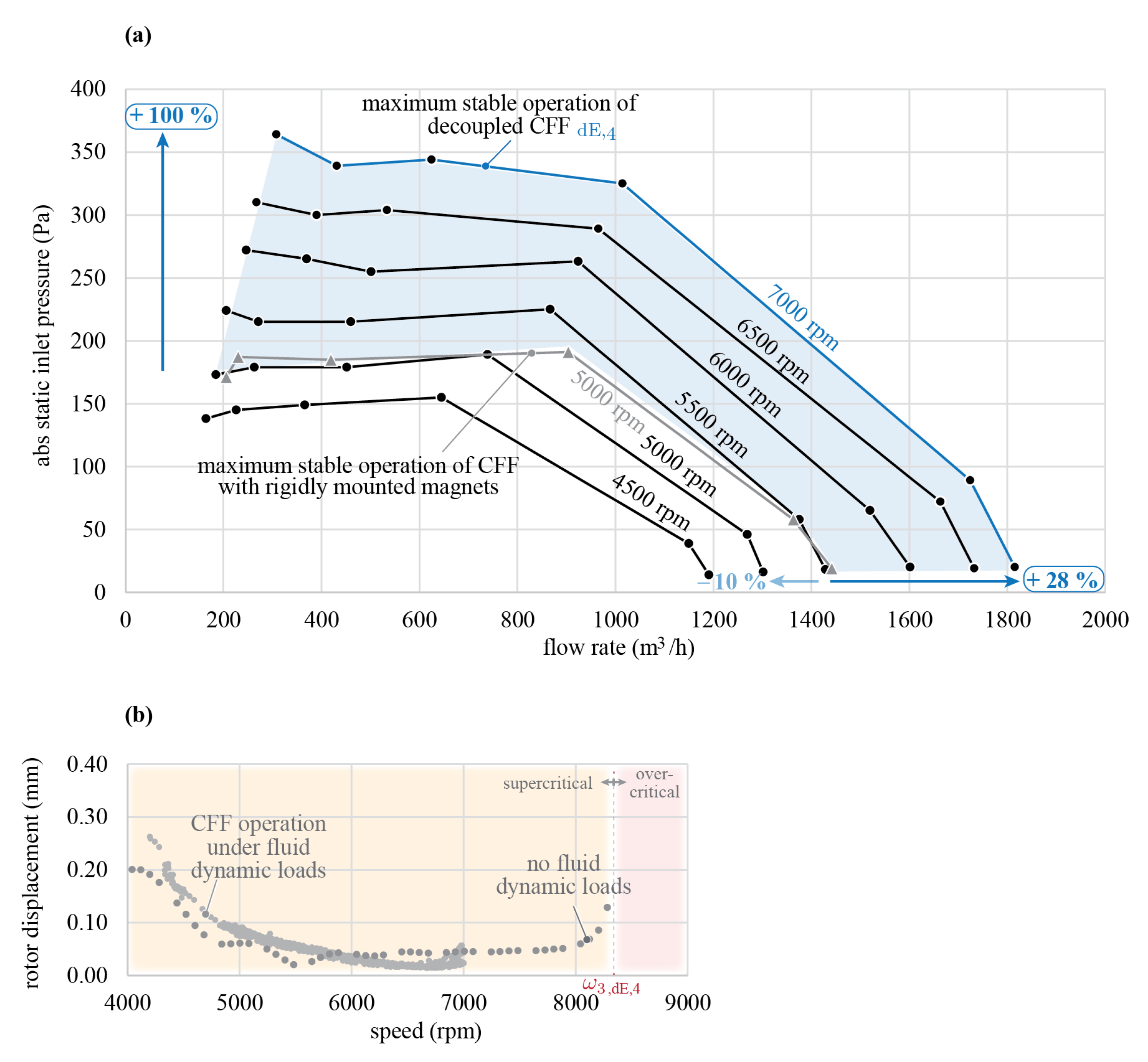
Figure 10a shows the resulting pressure-flow curves of the decoupled, supercritically operated rotor
and the subcritically operated CFF with rigidly mounted rotor magnets, which have been performed on a standardised test setup [
1]. The measurements marked in blue show the performance at the speed maximum of 7000 rpm, 17% below the third resonance frequency expected at 8400 rpm. The previously highest rotational speed of the directly coupled CFF at 5000 rpm is marked in grey, which is 14% below the expected bending resonance frequency of 5800 rpm.
Comparing the performance at 5000 rpm of the directly coupled and decoupled CFF, a decrease in flow rate of 10% is noticed (light blue arrow). This can be justified with a reduced active CFF blade length since for the decoupled CFF, auxiliary touch-down bearings are installed as a safety measure. Therefore, the 40% increase in rotational speed results in an overall increase in fluid flow of 28% and an increase in pressure of 100%.
Analysing the measured radial rotor displacements in the magnetic bearing of the CFF rotor under fluid dynamic loads (
Figure 10b), it can be concluded that a stable operation is possible up to 7000 rpm due to the self-centring effect of supercritical operation and that the fluid dynamic forces only cause small displacements in the magnetic bearing.
5. Discussion and Conclusions
The presented method of decoupling the rotor magnets of bearingless CFFs with mechanical elements of lower bending stiffness compared to the CFF blades, results in an increase in rotational speed and fluid dynamical performance. It is shown, that the blade damaging resonance is shifted to higher frequencies, enabling higher rotational speeds due to the self-centring effect of the rotor. This results in a 40% speed increase and leads to an increase in fluid flow of 28% and an increase in pressure of 100% compared to the previously presented bearingless CFF without decoupling elements.
To achieve a high-speed and high-performance bearingless CFF, the challenge is to increase the rotational speed with measures, that do not negatively impact the fluid dynamic performance.
Methods to increase the rotors’ mechanical stiffness and thus the achievable speed, e.g., through design adaptations such as thicker blades or axial rods for rotor stiffening, mostly result in lower fluid performance. Nevertheless, our approach still allows us to expand the CFF design with measures to increase the CFF blades’ stiffness.
To the authors’ knowledge, there is no comparable control strategy for bearingless motors to pass the bending resonance frequency without the risk of damaging the CFF blades, especially due to their unique mass distribution and bending stiffness. In comparison, the presented approach shifts the blade damaging resonance frequency to higher rotational speeds, hence ensuring that the rotor does not have to be operated in its vicinity or even to pass it.
In summary, the presented method offers a space-saving, simple yet effective mechanical design approach to increase the bearingless’ CFFs fluid dynamic performance.
