Abstract
Torque fluctuations in drivetrains are the result of dynamic excitations and can be unfavorable for the lifetime of the system. Passive ripple suppression methods exist, such as torsional dampers and flywheels, which are often bulky and not always desired. Alternatively, performant active control methods exist; however, their applicability to certain drivetrains is not covered. Therefore, this paper focuses on active control from a mechanical perspective, more specifically, drivetrain dynamics impacting active control effectiveness. A quasi-resonant controller is implemented as an active control method, and its performance and robustness are proven both in simulation on a 3-DOF mechanical model and experimentally at different excitation frequencies. The tests show that active control effectiveness is highly drivetrain-dependent. In particular, the propagation of the torque oscillation is influenced by the elastic filtering properties of the drivetrain, and the speed ripple depends on the inertial attenuation of the drivetrain. High-stiffness, low-inertia drivetrains benefit best from active control for ripple suppression because the inertial attenuation is limited, while high-stiffness elements increase the mechanical bandwidth before dynamic decoupling happens between the inertias of interest. Active control serves as a viable alternative for speed ripple reduction when drivetrain compactness is key, instead of the current passive solutions.
1. Introduction
1.1. Problem Statement and Literature Review
Drivetrains often suffer from unfavorable, hard-to-detect, and potentially problematic torsional ripples. The torsional vibrations, both on the drive and non-drive sides, can be induced by several aspects in and around the drivetrain. For instance, in electric motors, the cogging torque and electromagnetic torque ripple can induce torsional vibrations due to slotting effects and the current harmonics [1]. In piston engines, the pulsating drive torque arises from non-continuous combustion strokes and the reciprocating movement of the pistons [2]. Wind turbine drivetrains may encounter induced vibrations as the result of aerodynamic effects on the wind turbine blades [3]. Similarly, torque oscillations in fluid-based machines result from pressure distribution [4], among other factors.
Cyclic loads cause wear and fatigue of various drivetrain components, e.g., shafts, gears, and couplings, which impact lifetime and result in premature failures. Additionally, the speed oscillations induce noise [5,6], and they might also induce additional power losses due to the continuous acceleration and deceleration of the drivetrain elements.
Three different application-dependent methods can be distinguished to reduce speed oscillations in a drivetrain: (i) Torsional vibrations can be reduced by tackling the issue at its source by improving the design of the machine, e.g., by employing specific design rules for electric motors to limit their cogging torque (e.g., rotor skewing [7], magnet slot improvements [8]) [1]. The same is true for wind turbine drivetrains, where shape-shifting blades are implemented to reduce loads [9]. Although this design approach can be successful, the specific design of some machines can become costly or even impossible due to the working principle of the machine, or in general, a re-design of an existing machine can also be undesirable.
(ii) Additional passive or active dampers can be added to filter out the torsional vibrations, e.g., the friction clutch in a car that filters out the dynamic excitation from the internal combustion engine to the rest of the transmission [10]. Flexible coupling links can be used between drivetrain elements to achieve torsional decoupling. An example of a complex but well-studied type of drivetrain is the hybrid electric vehicle (HEV), which contains multiple vibration sources and several solutions to tackle the noise, vibration, and harshness problems they face [11]. Several implemented solutions include, e.g., increasing the flywheel inertia to filter the oscillations in a HEV [12] or introducing a torsional damper in the drivetrain, like a tuned mass damper. But it only works on one specific frequency [13,14,15].
There is, however, a general tendency to limit the number of drivetrain components to reduce manufacturing costs and obtain a more compact drivetrain. Other potential negative effects cannot be neglected either. Introducing damping elements can affect efficiency and even impact vehicle dynamics in HEVs.
(iii) Active damping control strategies can, therefore, become the most viable option because neither additional drivetrain components nor redesigns are required. Examples are active control of the electric motor in a hybrid vehicle’s powertrain to compensate for the fluctuating drive torque of the internal combustion engine [2,16], clutch control strategies to suppress vibrations in the transmission of vehicles [14,17], and electric machine active damping control methods to suppress the speed ripples [18,19,20,21].
Integrating active damping requires adaptations to the standard control. Currently, speed and current PI-controllers based on field-oriented control (FOC) are well known in electric drive control thanks to their performance in static load conditions. Nevertheless, the limited bandwidth of the PI controllers makes the rejection of dynamic load torque fail at higher frequencies [22,23]. Therefore, more advanced control methods are adopted to tackle dynamic disturbances, e.g., neural networks. However, they introduce additional computational complexity [24]. Alternatively, a look-up table comprising the waveform of the load machine’s dynamic excitation can be used and added as a compensation signal, but it lacks robustness as this dynamic excitation can change with various operating points and/or ambient conditions [25,26]. On the other hand, when dealing with a periodic disturbance, iterative learning control (ILC), repetitive control, and resonant control can be applied [20,21,27,28,29,30]. Regardless, ILC and repetitive control require data storage, and noise buildup has to be addressed during the learning process. A variable sampling frequency for repetitive control results in difficulties in adapting to changing disturbance frequencies [18]. Meanwhile, resonant control merely adds a parallel controller to the PI’s of the already existing control to improve drivetrain dynamics. It is a promising control strategy that has been compared with other active control methods and is seen as a popular approach [31,32], as proven by the various applications where it is applied, e.g., photovoltaic power condition systems [33], electric linear motor harmonic suppression [34], converters for grid applications [35,36], and electrical drives in general [21,37]. Active control (in general) increases dynamic response and is of value for torque and speed ripple reductions, especially in cases where the previously mentioned alternatives do not provide desired results.
1.2. Aim and Scope
Except for the application-oriented studies on active control discussed in the introduction, more often than not, contributions on active control methods are focused on the control aspect, studying performance, stability, robustness, etc., while not considering the feasibility aspect from a mechanical perspective. Therefore, this paper aims to demonstrate that the effectiveness of active control is highly dependent on the mechanical bandwidth of the drivetrain. It introduces a multidisciplinary approach, considering control and the drivetrain dynamics. Based on its performance proven in literature, its ease of implementation, and its popularity, the (quasi-)resonant controller is chosen and implemented as active control. This study identifies two further mechanical factors affecting the effectiveness and performance of active control, thereby indicating which type of drivetrain active control is best suited to achieve torque ripple reduction. The results are validated in an experimental setup where the mechanical filters have a low bandwidth per design.
1.3. Paper Structure
The outline of the paper is structured as follows: Section 2 is about the modeling of the employed control methods, and the drivetrain is modeled using the principles of classical mechanics and electromagnetism. Afterward, in Section 3, the experimental drivetrain is introduced, the adequate active control strategy on the drive motor is studied, and stability is analyzed. Then, its performance to compensate for dynamic load excitations is studied. This is achieved in simulation and validated on an experimental setup. Further interpretation of the mechanical filters, based on the obtained results, is discussed in Section 4. Finally, conclusions about active control and its applicability from a mechanical perspective are formulated in Section 5.
2. Modeling and Control
The complete drivetrain is modeled using the principles of classical mechanics and electromagnetism, following the works of [5,38] for the mechanical and electrical models, respectively.
2.1. Mechanical Drivetrain Model
2.1.1. Rigid Drivetrain
The application of the rotational equivalent to Newton’s second law on a rigid drivetrain gives the following equation:
with the drivetrain’s total polar mass moment of inertia ; the linear friction coefficient , assumed constant; the rotational speed ; the drive and load torque and , respectively; represents time. Converting Equation (1) into the Laplace domain results in the rigid drivetrain’s transfer function , given in Equation (2):
with the mechanical time constant ; stands for the Laplace variable. Hence, a rigid drivetrain can be modeled as a first-order filter between the external torques acting on the drivetrain and the drivetrain’s rotational speed; this filter is further denoted as the inertial mechanical filter.
2.1.2. Elastic Drivetrain
The elastic properties, i.e., the compliance effects of drivetrains, become important when high-frequency dynamic excitations are present. To analyze the drivetrain dynamics in these circumstances, a model is constructed where each drivetrain component is represented by polar inertia connected with torsional springs and damper elements. This results in a high-dimensional model that can often be reduced to a lower-order model. For the sake of clarity, a 3-DOF model is described in this paragraph to discuss the governing equations, as visualized in Figure 1, where the load machine () is driven by a drive motor (), connected to couplings, and a central shaft with relatively high polar inertia (). This high-inertia central shaft represents a lumped set of elements, such as, e.g., a belt drive, couplings, or a gearbox for geared applications.
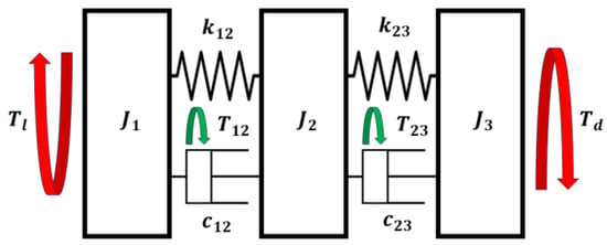
Figure 1.
A 3-DOF reduced mechanical drivetrain model. , , and represent the load machine, central shaft (representing a lumped set of shaft elements), and drive motor, respectively. The spring and damper elements represent couplings that interconnect elements i and j. and represent the drive and load torques, respectively. is the transmitted torque over the couplings. The arrows show in which direction the (positive) torque acts.
The application of the rotational equivalent of Newton’s second law to all inertias can be combined in a matrix equation as follows:
where , , and are the polar inertia, torsional stiffness, and viscous damping matrices, respectively. , , , and represent the external torque, rotational angle, speed, and acceleration vector, respectively. To determine the natural frequencies, a harmonic solution of the following form is introduced:
where is the natural pulsation of the torsional vibrations, belonging to the exponential that contains the temporal information of the vibrations, while the arbitrary contains the amplitude and phase information of these vibrations. The combination of Equations (3) and (4) results in the following:
the well-known frequency-domain representation of a mass–spring–damper system’s dynamics. Such a system has natural frequencies with corresponding resonance mode shapes. To find the natural frequencies and mode shapes, a mathematical eigenproblem must be solved for the undamped and non-driven system (. The solution to the eigenproblem becomes:
where det(.) represents the determinant operator. The solutions of Equation (6) are the eigenfrequencies of the system; introducing them into Equation (5), still assuming an undamped and non-driven system, gives the mode shapes of the system.
The importance of the elastic drivetrain model is that it allows to model the propagation of the excitations from one end of the drivetrain to the other end, which can be damped or amplified depending on the frequency.
In most cases, the inertia and stiffness properties of a drivetrain are known via CAD drawings and/or datasheets or obtained with finite element calculations. The damping terms of the interconnections can be estimated using the following:
where is the damping ratio, is the stiffness of the connection under study, and is the resonance pulsation at which this specific connection is under a large torsion moment. For mechanical parts in a drivetrain, typical values of 1–2% are used for . For elastic couplings with polymer or rubber components, the damping value is much higher and is often stated in the datasheet. The different drivetrain parameters are given in Table A1, Table A2 and Table A3.
2.2. Electrical PMSM Model
The drive motor is a three-phase interior Permanent Magnet Synchronous Motor (iPMSM). The electrical equations are given in the rotor reference dq-frame as follows [39], where and are the d- and q-axis voltages, currents and inductances, respectively; is the flux-linkage in the d-axis due to the permanent magnets in the rotor, is the stator resistance; and is the polepair number. This yields:
The d- and q-axis currents produce an electromagnetic torque that can be calculated as:
2.3. Field-Oriented Control
Field-oriented control (FOC) is an established and well-known electric motor current control method and is most commonly used with PI controllers in the industry [22,39,40,41]. It consists of decoupling the dq-axes by aligning the d-axis with the motor permanent magnet (PM-) flux. Here, FOC is employed as an inner loop current control within the outer loop speed controller. The current control strategy used is the so-called Maximum Torque per Ampere (MTPA) control strategy [42]. All PI controllers are implemented with the following transfer function:
The current PI-controller gains are tuned based on the pole-zero cancellation principle for a first-order system, which eliminates the dominant pole and allows the choice of a cut-off frequency of the closed loop system. Feedforward is implemented to compensate for the back-electromotive force. The current loop cut-off frequencies are set to The speed controller is similarly tuned based on pole-zero cancellation of a first-order transfer function of a rigid drivetrain with the choice of a cut-off frequency . It can be tuned independently of the current control, as the latter can be assumed to have infinitely faster dynamics. The control block diagram is visualized in Figure 2. The rigid drivetrain parameters are given in Table A2. The gains and time constants for all PI controllers are summarized in Table A4 for the drive motor and Table A5 for the load motor. The parameters of the power electronics converter (PEC) employed as drive are given in Table A6.

Figure 2.
Block diagram of the field-oriented control strategy.
2.4. Resonant Control
The bandwidth of the classic PI speed controller is limited as its purpose is to suppress constant speed errors. Fluctuating dynamic excitations are only slightly attenuated. The obtained attenuation gets worse for higher frequencies. For this reason, the resonant controller is implemented to cope with the dynamic component of the load torque and is placed in parallel with the FOC speed controller, as visualized in Figure 3. As mentioned earlier, different options exist to achieve speed and torque oscillation reduction. A resonant controller is chosen based on its proven attenuation capabilities and its easy implementation as an extension of an existing speed controller [18,28,29,43,44].

Figure 3.
Block diagram of the field-oriented control strategy with the addition of a resonant controller in the parallel path of the PI-speed controller.
The basic resonant controller, following the internal model principle (IMP), has the same denominator as the Laplace transform of a sine wave time signal [45,46]:
where and are the gain and resonance pulsation of the resonant controller, respectively. Only the gain is free of choice for the user, as the resonance pulsation should match the frequency of the dynamic excitation that is imposed on the drivetrain. To increase robustness, and since the frequency of the excitation is not always a priori known, a dampening effect can be added to the resonant controller, resulting in the so-called quasi-resonant controller with the following transfer function [47]:
where is the bandwidth of the quasi-resonant controller. The addition of the resonant controller to the regular PI speed controller extends the bandwidth of the control around a frequency level that can be chosen by the user, considering the right damping factor. The latter reduces the gain at that frequency from infinity to a finite value when compared to the resonant controller without a damping term but increases robustness.
3. The Resonant Controller: Simulation and Experimental Validation
In this section, the resonant controller is simulated and validated on an experimental test setup. First, the test setup is described, then the stability of the PI and quasi-resonant controller for the setup is studied, and finally, simulation and experimental results are shown.
3.1. The Experimental Drivetrain
The experimental drivetrain consists of a shaft and two IPMSMs. One acts as a drive motor, the other as a load motor. Both motors are connected to a central shaft with a coupling and a torque transducer. The shaft acts solely as an additional inertia to the drivetrain. The experimental setup is shown in Figure 4. The parameters of the drive and load motors are shown in Table 1.
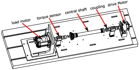
Figure 4.
The drivetrain test setup is used for the experimental validation of the models and associated simulations.

Table 1.
The nominal parameters of the drive and load motors.
The drivetrain can be represented by a 12-Degree of Freedom (DOF) torsional model, as depicted in Figure 5. The required parameters are given in Table A1. However, such high-DOF models are not intuitive to work with and are not required to understand the drivetrain dynamics in the vicinity of the lower resonance frequencies. They also increase the computational burden. Therefore, reduction methods exist where inertia and compliances are lumped together to form a lower-order model. For the present drivetrain, the distribution of the inertias and compliances allows for a reduction to 3-DOF, where the two motors and the central shaft in its housing are the dominant inertias. The main compliance effects are coming from the couplings and torque transducers. This is In line with the elastic model. The reduction is performed with Rivin’s algorithm [48], with the results listed in Table 2 and (repeated in) Table A3.

Figure 5.
The 12-DOF mechanical drivetrain model with inertia–spring–damper elements. The 12-DOF model is only used for determining the mode shapes, where damping elements are not included by definition.

Table 2.
The parameters of the 3-DOF mechanical drivetrain model.
When Equation (6) is solved for the present drivetrain in both the 12- and 3-DOF versions, the mode shapes of Figure 6 are obtained.
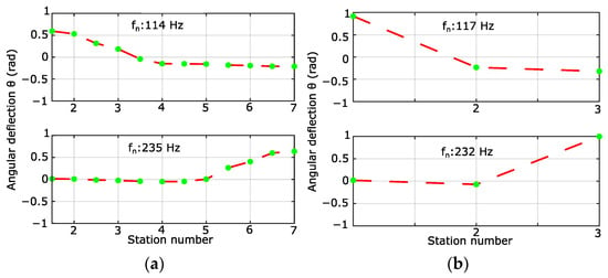
Figure 6.
Mode shapes for the elastic drivetrain model. (a) 12-DOF model, with the first and second resonant frequencies at 114 Hz and 235 Hz, respectively; (b) reduced 3-DOF model, with the first and second resonant frequencies at 117 Hz and 232 Hz, respectively.
The reduction in the model to a 3-DOF model has only a small impact on the location of the resonance frequencies. Moreover, the mode shapes of the 3-DOF model show a clear decoupling of the torsional resonances. At the first resonance frequency, the load (Station number 1) oscillates out of phase with respect to the central shaft and the motor together. While at the second resonance, the motor (Station number 3) oscillates out of phase with respect to the other two inertia’s, the same is also visible on the 12-DOF system. Therefore, it can be said that the load and the motor are decoupled at their respective torsional resonance frequencies, as the oscillations are not transmitted further, as visualized with the mode shapes.
The drivetrain torsional model represents the real drivetrain quite well up until at least the second resonant frequency. This is confirmed by the color plots in Figure 7. To obtain Figure 7, torsional vibration analysis is performed with an LMS data-acquisition module on the drivetrain to validate the simulated observations regarding the torsional resonances and introduce the notion of dynamic decoupling. This analysis consists of measuring the signals from the two torque transducers at the drive and load sides during a sweep over the rotational speed of the drivetrain. The obtained data from the torque transducers are then put under a Fourier decomposition, resulting in the color plots.

Figure 7.
Color plots were obtained through torsional vibration analysis, visualizing the Fourier amplitude spectrum of the measured torque signal for various rotational speeds of the drivetrain. (a) Load-side torque transducer. (b) Drive-side torque transducer.
The torsional resonance frequencies are independent of the rotational speed of the drivetrain; these frequencies can, therefore, be identified as vertical lines of increased torque levels triggered by the different orders of the operating speed during the sweep-up. With this reasoning, Figure 7 shows, in the given frequency range, two torsional resonances at 115 and 233 Hz, closely corresponding to the ones found theoretically, as shown in both plots of Figure 6.
As can be seen, the torsional resonances are not as pronounced in both plots since the load-side torque transducer experiences a higher torque level at the first resonance compared to the torque transducer on the drive side. The opposite applies in the vicinity of the second torsional resonance. This color plot behavior was predicted by the model mode shapes visualized in Figure 6. The mode shape at 115 Hz shows that there is no significant twist between the inertia and inertia , which is confirmed by the experimental test since the drive-side torque transducer does not show a significant torque level at 115 Hz. Vice versa, the same is true for the mode shape at 233 Hz. No significant twist is present between the inertia and inertia , and no significant torque level is measured at the load-side torque transducer. This shows that both mode shapes are decoupled from each other.
3.2. Controller Stability and Design
To prove the stability of the speed control loop on the experimental setup and obtain insight into the control parameter design, the open-loop speed control bode diagrams are studied. The control system includes the reduced 3-DOF mechanical model with friction and the resonant controller in parallel with the PI-speed controller (as in Figure 3). The PI-speed controller has fixed parameters since the quasi-resonant controller is added to an existing stable speed control loop. The current controller dynamics are an order of magnitude faster; therefore, their influence is neglected for the speed control loop. All poles of the open loop system contain negative real parts, resulting in bounded input bounded output stability of the open loop system.
The resonant controller has three parameters to be defined: the resonant controller gain , the bandwidth pulsation and the resonant pulsation . The influence of each parameter is depicted in Figure 8. In order to evaluate the sensitivity, only one parameter has been adapted per subfigure. Assuming the load torque frequency is known, the resonant pulsation is fixed accordingly. The reference values of the different controller parameters are , , and . The presence of the quasi-resonant controller is clearly visible with the peak at the resonant pulsation . The peaks at 117 Hz and 232 Hz are the torsional resonance frequencies of the mechanical 3-DOF system.
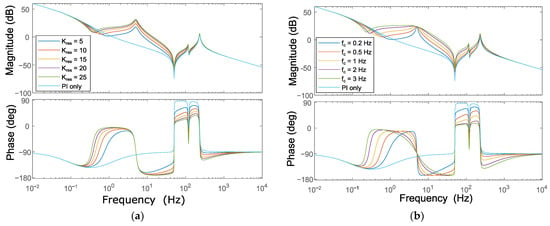
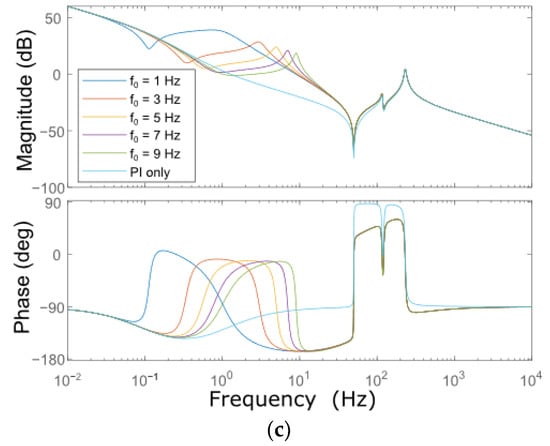
Figure 8.
Bode Diagrams of the open loop control system. The reference values of the resonant controller used are , and . (a) Sensitivity of , (b) sensitivity of , and (c) sensitivity of .
The influence of shows a clear magnitude increase around the resonance pulsation in Figure 8a. This means the steady state remaining speed ripple will lower for higher . Regarding the stability of the closed-loop system, changing will lower the phase margin, which might compromise stability. has a dampening effect around the resonant frequency of the quasi-resonant controller, as shown in Figure 8b. A higher value can be set when the load torque frequency is not known a priori. Increasing results in a peak shift of the resonance frequency and a lower amplitude at this peak. Furthermore, it shows a decreased dampening effect for a constant . To keep the same dampening effect, changing proportionally with is required, as was conducted in [49].
The set values of the quasi-resonant controller parameters for the following simulations and experiments are in Table 3. The value of was chosen together with based on transient response to avoid overloading the drive motor. Also, the goal was to reach a steady state ripple of only a few percentages of the nominal speed. could stay relatively low since the load torque frequency is known a priori during the tests, thereby improving the speed oscillation rejection at the quasi-resonant resonance frequency. The resulting gain and phase margin, and , respectively, are shown in Figure 9a and prove closed-loop stability.

Table 3.
Quasi-resonant controller parameters.
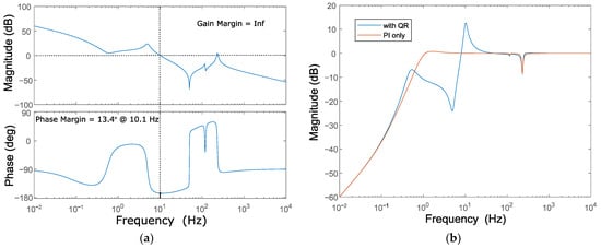
Figure 9.
Bode diagrams of the studied system with resonant control parameters: , and . (a) Open-loop bode diagram with gain and phase margins; (b) disturbance rejection closed-loop bode diagram.
The corresponding closed-loop speed disturbance rejection bode diagram is depicted in Figure 9b for . It shows, indeed, a strong attenuation of the speed ripple at the resonance frequency of the quasi-resonant controller while increasing the ripple further when the load torque frequency is too high with respect to the quasi-resonant controller rejection frequency . This could be attenuated again with an increased dampening effect.
3.3. Simulation Results
To show the performance of the resonant controller, a simulation model is set up based on the experimental drivetrain. The drivetrain is modeled as a 3-DOF mechanical model. The load torque is applied directly to the load inertia station, while the drive-side machine is controlled by FOC and a quasi-resonant filter to suppress the speed oscillations measured at the drive side. As mentioned, the quasi-resonant controller requires an approximate knowledge of the torque perturbation frequency to work optimally. In the following simulations, it is assumed that the controller and the torque perturbation frequency match.
In the simulations, a sinewave load torque is applied with an amplitude of 3 Nm and an offset of 3 Nm at multiple frequencies (3, 5, and 15 Hz); the reference speed is 1000 rpm. The quasi-resonant control is switched on at 5 s. Figure 10 shows the resulting speed of the drive-side machine. The quasi-resonant control works well once a steady state is reached since the original speed ripple almost disappears completely, although the remaining ripple is slightly larger for higher frequencies, which is related to the active control performance. However, before the quasi-resonant controller is on, a speed ripple attenuation is already visible as the speed oscillation amplitude decreases with increasing frequency. This is due to the relatively high inertia of the central shaft, which works as a flywheel, thereby passively attenuating the speed ripple.
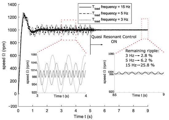
Figure 10.
Simulated speed of the drive motor is subject to a load torque of multiple frequencies (3, 5, and 15 Hz). The load torque is 3 Nm, with an additional sinewave ripple of 3 Nm. A quasi-resonant controller is switched on at 5 s. Two enlarged figures are provided: one to show the decreasing ripple for increasing frequencies before the use of the quasi-resonant control (3–4 s) and another to show the (relative) effect of the quasi-resonant control (8.5–9 s).
The effects of the oscillating load and control on the shaft torques are shown in Figure 11 for a load torque frequency of 1 and 5 Hz in Figure 11a,b, respectively, together with a torque offset to overcome the friction torque. For the lower frequency, in Figure 11a, the PI control, without the resonant control, results in a slight phase-shifted torque ripple on the gear-drive shaft with respect to the torque ripple on the load-gear shaft. For the higher ripple frequency, in Figure 11b, the phase shift is higher while the amplitude is lower (1.2 Nm with respect to 8.2 Nm). This difference is due to the bandwidth of the PI controller. The purpose of a PI controller is to compensate for constant errors, and it cannot handle ripples properly. Having a more aggressive PI controller will handle oscillations better and up to a higher frequency, but an aggressive PI controller lowers robustness. Using a parallel-placed quasi-resonant controller solves this issue; more precisely, the phase shifts disappear completely, and the amplitude of the drive motor torque matches the load torque amplitude of 6 Nm.
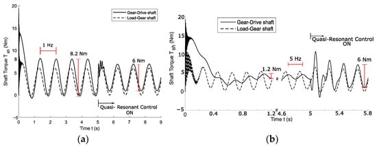
Figure 11.
Simulated shaft torques of the 3-DOF model of the drivetrain, where the load torque is 3 Nm with an additional sinewave ripple of 3 Nm. The quasi-resonant controller is switched on at 5 s. The sinewave load torque ripple is (a) 1 Hz and (b) 5 Hz.
In relative numbers, for the three frequencies, 3 Hz, 5 Hz, and 15 Hz, the remaining speed fluctuation is 2.8%, 6.2%, and 25.8% of the original fluctuation, respectively. This decrease in relative effectiveness is due to the lower initial speed ripple, which is caused by the high inertia present in the drivetrain, acting as an inertial attenuator. Although the resonant filter seems less effective at higher ripple frequencies due to the inertial attenuation, it actively lowers the speed ripple to a maximum of 8 rpm pk–pk regardless of the ripple frequency. This clearly shows that the performance of the active controller is highly affected by the mechanical bandwidth of the drivetrain. Consequently, it also shows that active control is especially interesting for relatively low (with respect to the torque oscillation levels) inertia drivetrains, with a higher mechanical bandwidth and a speed attenuation that is less pronounced, resulting in a higher speed ripple for the same torque oscillation amplitude. The inertial filter is explained in more detail in Section 4.1.
3.4. Experimental Results
The active control with the quasi-resonant controller proves to be effective and robust in the experimental setup described earlier. AdSPACE MicroLabBox II with software version 2021.B is used for data acquisition and rapid control prototyping. The experimental test is depicted in Figure 12.
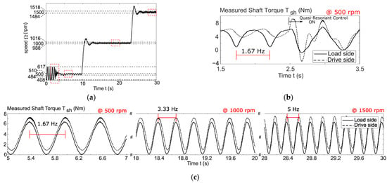
Figure 12.
Experimental results. The reference sinewave load torque has an offset of 3 Nm and an amplitude of 3 Nm, and the frequency is speed-dependent and set to of the actual speed. The quasi-resonant controller is set to mitigate the speed ripple at 1000 rpm and turned on at 2.5 s. The speed reference goes in steps from 500 to 1000 to 1500 rpm, while the load torque frequencies go from 1.67 to 3.33 to 5 Hz, respectively. (a) The measured speed; (b) the measured shaft torques when the quasi-resonant controller is turned on; (c) the measured shaft torques in a steady state at different speeds.
During the whole test, the reference sinewave load torque had an offset of 3 Nm and an amplitude of 3 Nm. The torque ripple frequency is speed-dependent and set to one-fifth of the reference speed to cover different ripple frequencies. The quasi-resonant controller is turned on at 2.5 s. The speed reference goes in steps from 500 to 1000 to 1500 rpm, while the load torque oscillating frequencies go from 1.67 to 3.33 to 5 Hz, respectively. Initially, the speed ripple is 200 rpm pk–pk at 500 rpm without the quasi-resonant control active. The initial speed ripple without active control would decrease for higher torque oscillating frequencies due to the inertial filter. However, this is not shown in Figure 12, since once the active control is activated, it is not turned off again.
The measured speed is shown in Figure 12a; the initial speed ripple of 200 rpm pk–pk is reduced to about 30 rpm pk–pk at the three different speeds. The test shows that, like in the simulations, the quasi-resonant controller can reduce the oscillations to the same level, regardless of the excitation frequency. Additionally, the resonant controller parameters are not altered during the whole test and kept at the ideal parameters for a ripple frequency of 3.33 Hz, while in simulation they were altered to stay ideal with the changing ripple frequency. This proves the robustness of the quasi-resonant controller, as the speed ripple is still diminished to 30 rpm pk–pk for the deviating ripple frequencies.
The shaft torques are visible in Figure 12b,c. The load-side torque shows the load torque at the shaft between the load machine and the gear, while the drive-side torque is measured at the shaft between the gear and the drive motor. It, therefore, reflects the torque reference of the PI and resonant speed controllers. In Figure 12b, it is visible that the PI controller alone cannot counteract the speed and torque oscillations properly; more precisely, there is a phase shift present, and the amplitudes do not match between the load and drive-side shaft torques. Once the resonant controller is turned on and the steady state is reached at different speeds, the phase shift disappears almost completely; the remaining offset is present to compensate for the friction present on the drivetrain. Figure 13 compares the simulation and experimental drive and load-side torques at a 5 Hz load torque ripple frequency. Properly identifying mechanical and electrical parameters to create a reliable model can be tedious. The experimental results closely resemble the simulation results, with the same friction offset and similar amplitudes of the torques, which validates the simulation model. The only difference is the phase shift of about between load and drive-side torques for the simulation and about for the experiment. This increased phase shift explains the higher remaining speed ripple for the experiments.
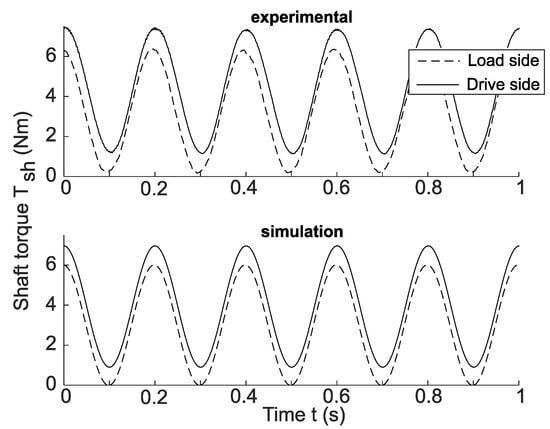
Figure 13.
Comparison between simulation and experimental load- and drive-side torques of the quasi-resonant controller at 5 Hz load torque ripple frequency.
4. The Inherent Drivetrain Factors Affecting Active Control
There are two types of drivetrain-specific factors that affect the effectiveness of active control. These factors are seldom mentioned in active control papers, as these discuss mainly the control aspects: performance, stability, robustness, etc. Therefore, this section covers these limits. A first factor was already encountered in the simulation results, where the speed ripple decreased for higher frequencies before turning on the resonant controller. This limit is related to the inertia present in the drivetrain. Also, the dynamic decoupling of the load and drive sides of the setup by the torsional resonances affects active control.
4.1. The Inertial Attenuation
The speed ripple finds its cause in a torque ripple of a certain amplitude, which comes, for example, from the load. The relationship between torque and speed is described by Newton’s second law. Considering a rigid drivetrain, Newton’s second law becomes Equation (1), and its transfer function, Equation (2), is repeated here for convenience:
where the time constant contains the drivetrain total inertia , and the friction coefficient . The bode plot of such a transfer function is depicted in Figure 14 This figure shows the decreasing amplitude of the speed ripple with an increasing frequency of the torque ripple. The attenuation gets less pronounced when the drivetrain inertia decreases. Since the graph with the central shaft in Figure 14 represents the experimental test setup, it explains why, in the experimental setup at hand, it is only possible to show the resonant control performance at relatively low ripple frequencies. It was already visible in the simulations in Figure 10 that at higher frequencies (15 Hz), the ripple disappears even without employing the resonant controller. This is due to the presence of the central shaft, which has a relatively high contribution to the drivetrain inertia in comparison to the torque ripple amplitude. In Figure 14, the smallest inertia shows the case where the central shaft high inertia component is removed from the drivetrain. An increase of 12 dB is obtained, which would result in a speed ripple four times higher. In actual applications, higher inertias usually go hand in hand with higher torque ripple amplitudes, thereby maintaining an important speed ripple anyway. The inertial attenuation with the central shaft explains why the initial ripple amplitude rapidly lowers with increasing ripple frequencies in the simulation and experiments.
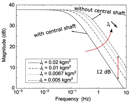
Figure 14.
Bode plot of a rigid drivetrain for decreasing total inertias. The biggest inertia ( is the actual experimental setup inertia, the smallest inertia () represents the setup inertia without the gear present.
This inertial attenuation is already well known and can be exploited for passive ripple attenuation by adding a big flywheel to the drivetrain, e.g., piston engines. The gear in the experimental setup takes on the role of a flywheel. Adding a flywheel for ripple attenuation is, however, a more costly solution, and it is less compact. Therefore, if adding a flywheel is unwanted or not possible, active control is a viable option for rigid drivetrains, as shown by the simulations and experimental results. More precisely, the control attenuated the speed ripple to 8 rpm pk–pk independently of the ripple frequency, proving the drivetrain-dependent effectiveness of the active control.
4.2. The Elastic Filter
Active control acts on the speed error between actual speed and reference speed, which is usually constant. To attenuate the speed ripple to acceptable levels, the control must first be able to observe the speed ripple and then be able to counteract its source. Considering the elasticity of the drivetrain, however, this is only possible in the frequency range beneath the relevant torsional resonance frequency of the drivetrain that dynamically decouples the drive motor and the torque ripple source (load) from each other. To understand the role of the elastic filter and the propagation of an applied torque through the drivetrain, a forced response torque analysis is required.
A forced torque response torsional analysis is shown in Figure 15a. As a forced torque oscillation, 1 Nm is applied to the drive motor inertia. Figure 15a clearly shows the resonance frequencies at both the load and drive sides of the drivetrain and reveals how a forced torque oscillation of 1 Nm propagates through this specific drivetrain from the drive side to the load side. The first resonance frequency is clearly visible in the load-side torque measurement, while it has almost no impact on the drive-side torque, which is in accordance with the first mode shape. For frequencies below this first resonance frequency, about 0.2 Nm remains at the load side. Above the first resonance frequency, the propagated torque from the drive to the load side is much lower, which is due to the presence of the second mode shape, where the drive motor has much less impact on the load-side torque. This is clearly visible at the second resonance frequency: 1 Nm of applied torque is amplified to 23 Nm at the drive side, while only 1.8 Nm remains at the load side. Therefore, torque oscillations coming from the drive motor’s active control will be effective beneath the first resonant frequency while being less effective above due to the lower propagation torque ratio from the drive to the load side. Figure 15b shows the ratio between the drive-side and load-side torques, and this shows that, indeed, above the first resonance frequency, active control will be ineffective, as almost no torque propagates through the drivetrain anymore.
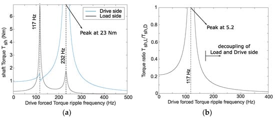
Figure 15.
Forced response torsional analysis of the 3-DOF model of the drivetrain. The forced torque of 1 Nm is applied by the drive motor. (a) The absolute shaft torques both at the drive and load side and (b) the ratio between drive- and load-side torques.
To reveal the drivetrain and direction dependency of the torque propagation for active control, the load inertia is now considered the counteracting torque oscillation source, and the forced response torsional analysis is given in Figure 16. The analysis, and especially Figure 16b, shows that torque propagation from the load to the drive side is lower than in the analysis where propagation is considered from the drive to the load side (Figure 15). This is due to the higher inertia of the load motor with respect to the drive motor. Therefore, active control will already be less effective. However, even though the propagation ratio is lower, the resonance frequencies are visible. At the first resonance frequency (117 Hz), the applied (load side) torque of 1 Nm is amplified to 20 Nm and propagated to the drive side, where 1.6 Nm remains. This is because the load-side torque is strongly amplified, as shown by the first mode shape. At the second resonance frequency, even a low torque at the load side is amplified to a higher torque level, which is in accordance with the second mode shape, where it mostly impacts the oscillations of the drive side. The torque ratio (drive-side torque overload-side torque), shown in Figure 16b, reveals that, indeed, torque propagation is already lower than in Figure 15b but completely disappears after the second resonance frequency.
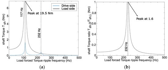
Figure 16.
Forced response torsional analysis of the 3-DOF model of the drivetrain. The forced torque of 1 Nm is applied by the load-side motor. (a) The absolute shaft torques both at the drive and load sides and (b) the ratio between load- and drive-side torques.
The relatively low resonance frequency is a result of the presence of flexible couplings weakly linking different parts of the drivetrain, which lowers the resonance frequency considerably and dynamically decouples certain drivetrain elements early on. As mentioned, the inertia of the drivetrain has an impact on the torque propagation too. Under the resonance frequency, higher inertia in the drivetrain results in a lower propagation ratio. Consequently, the mechanical bandwidth and impact of the active control are limited by the inertial attenuation and the elastic filter. Therefore, it is concluded that active control is most effective in stiff, direct-drive drivetrains with high resonance frequencies.
To prove the benefit of direct-drive drivetrains for active control, a simulation is run with a 2-DOF model, where the central shaft with high inertia is virtually removed from the experimental setup. It results in only the load inertia being attached with a flexible coupling to the drive motor. Drivetrains with higher stiffness and less flexible couplings result in increased compactness where the torque ripples from the load will reach the drive motor less attenuated and vice versa, while also the first resonance frequency lies higher, which means the dynamic decoupling of both sides happens at higher frequencies. The decreased inertia of the drivetrain also results in a lower inertial attenuation of speed ripple.
The simulation results are shown in Figure 17 and Figure 18. Due to the strongly decreased drivetrain inertia, the propagation torque ratio, shown in Figure 17, lies higher (the graph of Figure 15b has been included as a comparison). Additionally, the increased torque ripple will result in an even higher speed ripple (due to the 12 dB difference shown in Figure 14). The performance of the active control for the stiffer 2-DOF model is illustrated in Figure 18 at three different load torque frequencies, namely, 15, 25, and 50 Hz. The load torque is a sinewave and has an offset of 3 Nm and an amplitude of 6 Nm pk–pk. The reference speed is 1000 rpm, and the quasi-resonant controller gains remain unchanged. The 15 Hz load torque simulation proves the higher initial speed ripple of the 2-DOF model with respect to the 3-DOF model, from 14 rpm to 65 rpm, proving the dB mentioned. After 5 s, the active controller is turned on. When a steady state is reached, the remaining speed ripple is 16 rpm pk–pk for both 15 and 25 Hz, while it is slightly higher for the 50 Hz load torque with 24 rpm pk–pk. This simulation shows again that, in absolute terms, regardless of the initial speed ripple, the quasi-resonant controller can consistently reach (almost) the same speed ripple, thereby proving the performance of the active control. For the stiffer 2-DOF model, however, a much higher initial speed ripple is present with respect to the 3-DOF model because of the decreased inertia and, therefore, decreased inertial attenuation. As postulated, when compared to the 3-DOF model, this shows that the performance of the active controller is highly dependent on the drivetrain’s mechanical bandwidth, which is limited by the inertial attenuation and the elastic filter.
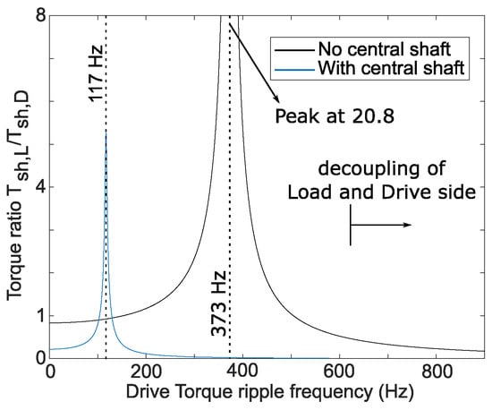
Figure 17.
Ratio between load-side and drive-side shaft torque for a forced response with a torque ripple applied on the drive motor. In blue, with the central shaft, as in Figure 15, is the 3-DOF model representing the experimental setup. In black, without a central shaft, for the direct-drive version of the experimental test setup modeled with a 2-DOF system.
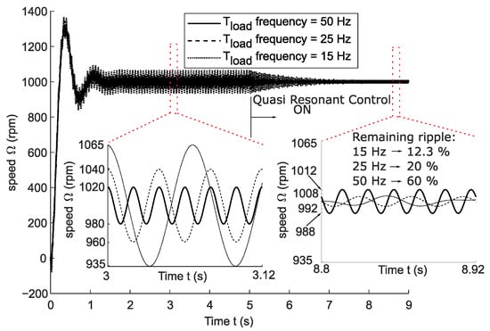
Figure 18.
Simulated speed of the drive motor in the stiff drivetrain, subject to a load torque of multiple frequencies (15, 25, and 50 Hz). The load torque is 3 Nm, with an additional sinewave ripple amplitude of 3 Nm. A quasi-resonant controller is switched on at 5 s. Two enlarged figures are provided: one to show the decreasing ripple for increasing frequencies before the use of the quasi-resonant control (3–3.12 s) and another to show the (relative) effect of the quasi-resonant control (8.8–8.92 s).
This simulation shows again that active control is an interesting alternative for speed ripple rejection instead of the intentional decrease in the drivetrain’s mechanical bandwidth caused by the addition of flexible couplings and big flywheels. This is because active control favors a more compact direct-drive drivetrain, as its performance benefits from the higher stiffness and compactness while also being less costly if the required hardware is nonetheless present.
5. Conclusions
In this paper, the quasi-resonant controller is implemented as an active control to suppress speed ripples by introducing a counteracting torque ripple. Its easy implementation complements the regular PI controller found in most drives by increasing the control bandwidth around a set frequency. The stability of the controller was proven, and simulation and experiments show the performance and robustness of the resonant controller against torque disturbance variations. The experiments on the test setup show a constant, remaining ripple of 15 rpm pk–pk for all the tested speed levels, independent of the torque ripple frequency.
The results have proven that the implemented active control’s performance is highly dependent on the mechanical bandwidth of the drivetrain. The drivetrain’s bandwidth, and thereby the active control’s performance, is from a mechanical perspective determined by two phenomena, more specifically, the inertial attenuation and the elastic filter. The high inertias present in a drivetrain act as an inertial flywheel, passively filtering out the speed ripple, while the presence of flexible elements in the drivetrain lowers the resonance frequencies and acts as a mechanical elastic filter by dynamically decoupling drivetrain elements from each other. Therefore, both factors impact the useful bandwidth of the quasi-resonant controller, regardless of the active controller’s bandwidth itself, as the controller remained unchanged in this study.
Stiff and compact direct-drive drivetrains have higher resonance frequencies and lower inertia, resulting in a higher bandwidth for active control and better performance. Therefore, this study also shows that active control is an interesting solution, instead of the addition of flexible couplings and big flywheels, for speed ripple issues, resulting in stiffer and more compact direct-drive drivetrains. This is in favor of the trend towards direct-drive drivetrains.
Author Contributions
J.C. and A.L.J.D. conducted the research and simulations; J.C., A.L.J.D. and J.B. conducted the experimental research; A.L.J.D., B.V. and J.C. conducted the mechanical modeling; B.V., J.B., W.D. and O.H. reviewed the paper; B.V., W.D. and O.H. supervised the research and contributed to the funding acquisition. All authors have read and agreed to the published version of the manuscript.
Funding
This research was funded by Flanders Innovation & Entrepreneurship (VLAIO), grant number HBC.2022.0155.
Data Availability Statement
Data are contained within the article.
Conflicts of Interest
The authors declare no conflicts of interest.
Appendix A
This appendix is devoted to the mechanical and electrical drivetrain models. Different tables with different parameters used throughout this study are given.
Inertia values come from the CAD models of each drivetrain element, and shaft stiffness values too. For the couplings and torque transducers, the datasheet values were used, and the couplings and damping coefficients were estimated based on Equation (7).

Table A1.
The parameters of the 12-DOF mechanical drivetrain model.
Table A1.
The parameters of the 12-DOF mechanical drivetrain model.
| Station | Inertia of … | ) | Connection | |
|---|---|---|---|---|
| 1 | Load Motor | 3749 | 1–2 | 18.4 |
| 2 | Coupling | 160 | 2–3 | 5.5 |
| 3 | Transducer | 280 | 3–4 | 17.1 |
| 4 | Coupling | 167 | 4–5 | 5.5 |
| 5 | Coupling | 160 | 5–6 | 11.7 |
| 6 | Gear | 7216 | 6–7 | 261.9 |
| 7 | Rotor | 7060 | 7–8 | 27.6 |
| 8 | Coupling | 160 | 8–9 | 5.5 |
| 9 | Coupling | 167 | 9–10 | 17.1 |
| 10 | Transducer | 280 | 10–11 | 5.5 |
| 11 | Coupling | 160 | 11–12 | 24.6 |
| 12 | Drive Motor | 632 |

Table A2.
Rigid drivetrain parameters.
Table A2.
Rigid drivetrain parameters.
| Parameter | |
|---|---|
| 0.013 | |
| 0.02 | |
| 1.55 |

Table A3.
The parameters of the 3-DOF mechanical drivetrain model.
Table A3.
The parameters of the 3-DOF mechanical drivetrain model.
| Station | ) | Connection | ||
|---|---|---|---|---|
| 1 | 4160 | 1–2 | 1.78 | 99 |
| 2 | 15,013 | 2–3 | 2.01 | 55 |
| 3 | 1019 |

Table A4.
FOC’s PI-controller parameters for the drive motor.
Table A4.
FOC’s PI-controller parameters for the drive motor.
| Parameter | |||
|---|---|---|---|
| Cut-off frequency (Hz) | 200 | 200 | 10 |
| Time constant (ms) | 8.48 | 11.21 | 1.55 |
| Gain | 3.36 | 4.44 | 1.27 |

Table A5.
FOC’s PI-controller parameters for the load motor.
Table A5.
FOC’s PI-controller parameters for the load motor.
| Parameter | ||
|---|---|---|
| Cut-off frequency (Hz) | 200 | 200 |
| (ms) | 15.13 | 39.87 |
| 2.89 | 7.62 |

Table A6.
PEC parameters.
Table A6.
PEC parameters.
| Parameter | Drive Motor | Load Motor |
|---|---|---|
| Switching frequency (kHz) | 4 | 4 |
| Sampling frequency (kHz) | 20 | 20 |
| Inverter time constant (ms) | 0.3 | 0.3 |
References
- Islam, M.S.; Mir, S.; Sebastian, T.; Underwood, S. Design considerations of sinusoidally excited permanent magnet machines for low torque ripple applications. In Proceedings of the Conference Record of the 2004 IEEE Industry Applications Conference, 39th IAS Annual Meeting, Seattle, WA, USA, 3–7 October 2004. [Google Scholar]
- Davis, R.I.; Lorenz, R.D. Engine torque ripple cancellation with an integrated starter alternator in a hybrid electric vehicle: Implementation and control. IEEE Trans. Ind. Appl. 2003, 39, 1765–1774. [Google Scholar] [CrossRef]
- Fateh, F.; White, W.N.; Gruenbacher, D. Torsional vibrations mitigation in the drivetrain of DFIG-based grid-connected wind turbine. IEEE Trans. Ind. Appl. 2017, 53, 5760–5767. [Google Scholar] [CrossRef]
- Salts, N.; Ziviani, D.; Groll, E.A. Application of a generalized compressor modeling framework for simulating an oil-injected twin-screw compressor. In IOP Conference Series: Materials Science and Engineering; IOP Publishing: Bristol, UK, 2019; Volume 604, p. 012009. [Google Scholar]
- Wachel, J.; Szenasi, F.R. Analysis of torsional vibrations in rotating machinery. In Proceedings of the 22nd Turbomachinery Symposium, Houston, Texas; Texas A&M University, Turbomachinery Laboratories: College Station, TX, USA, 1993. [Google Scholar]
- Corbo, M.A.; Melanoski, S.B. Practical Design Against Torsional Vibration. In Proceedings of the 25th Turbomachinery Symposium; Texas A&M University, Turbomachinery Laboratories: College Station, TX, USA, 1996. [Google Scholar]
- Gan, C.; Wu, J.; Shen, M.; Yang, S.; Hu, Y.; Cao, W. Investigation of skewing effects on the vibration reduction of three-phase switched reluctance motors. IEEE Trans. Magn. 2015, 51, 1–9. [Google Scholar] [CrossRef]
- Jung, J.-W.; Lee, S.-H.; Lee, G.-H.; Hong, J.-P.; Lee, D.-H.; Kim, K.-N. Reduction design of vibration and noise in IPMSM type integrated starter and generator for HEV. IEEE Trans. Magn. 2010, 46, 2454–2457. [Google Scholar] [CrossRef]
- Das, S.; Sajeer, M.M.; Chakraborty, A. Vibration control of horizontal axis offshore wind turbine blade using SMA stiffener. Smart Mater. Struct. 2019, 28, 095025. [Google Scholar] [CrossRef]
- Li, L.; Lu, Z.; Liu, X.-L.; Sun, T.; Jing, X.; Shangguan, W.-B. Modeling and analysis of friction clutch at a driveline for suppressing car starting judder. J. Sound Vib. 2018, 424, 335–351. [Google Scholar] [CrossRef]
- Qin, Y.; Tang, X.; Jia, T.; Duan, Z.; Zhang, J.; Li, Y.; Zheng, L. Noise and vibration suppression in hybrid electric vehicles: State of the art and challenges. Renew. Sustain. Energy Rev. 2020, 124, 109782. [Google Scholar] [CrossRef]
- Morandin, M.; Bolognani, S.; Pevere, A.; Calligaro, S.; Petrella, R. Active torque ripple damping in direct drive range extender applications: A comparison and an original proposal. In Proceedings of the 2015 IEEE Vehicle Power and Propulsion Conference (VPPC), Montreal, QC, Canada, 19–22 October 2015. [Google Scholar]
- Tang, X.; Hu, X.; Yang, W.; Yu, H. Novel torsional vibration modeling and assessment of a power-split hybrid electric vehicle equipped with a dual-mass flywheel. IEEE Trans. Veh. Technol. 2017, 67, 1990–2000. [Google Scholar] [CrossRef]
- Minh, V.T.; Pumwa, J. Fuzzy logic and slip controller of clutch and vibration for hybrid vehicle. Int. J. Control Autom. Syst. 2013, 11, 526–532. [Google Scholar] [CrossRef]
- Mall, P.; Fidlin, A.; Krüger, A.; Groß, H. Simulation based optimization of torsional vibration dampers in automotive powertrains. Mech. Mach. Theory 2017, 115, 244–266. [Google Scholar] [CrossRef]
- Cauet, S.; Etien, E.; Rambault, L. Mechanical sensorless LPV torque ripple control of hybrid electric vehicle. IET Control Theory Appl. 2017, 11, 2761–2771. [Google Scholar] [CrossRef]
- Walker, P.D.; Zhang, N. Active damping of transient vibration in dual clutch transmission equipped powertrains: A comparison of conventional and hybrid electric vehicles. Mech. Mach. Theory 2014, 77, 1–12. [Google Scholar] [CrossRef]
- Zhang, Q.; Guo, H.; Guo, C.; Liu, Y.; Wang, D.; Lu, K.; Zhang, Z.; Zhuang, X.; Chen, D. An adaptive proportional-integral-resonant controller for speed ripple suppression of PMSM drive due to current measurement error. Int. J. Electr. Power Energy Syst. 2021, 129, 106866. [Google Scholar] [CrossRef]
- Liu, J.; Li, H.; Deng, Y. Torque ripple minimization of PMSM based on robust ILC via adaptive sliding mode control. IEEE Trans. Power Electron. 2017, 33, 3655–3671. [Google Scholar] [CrossRef]
- Rafaq, M.S.; Midgley, W.; Steffen, T. A Review of the State of the Art of Torque Ripple Minimization Techniques for Permanent Magnet Synchronous Motors. IEEE Trans. Ind. Inform. 2024, 20, 1019–1031. [Google Scholar] [CrossRef]
- Chuan, H.; Fazeli, S.M.; Wu, Z.; Burke, R. Mitigating the Torque Ripple in Electric Traction Using Proportional Integral Resonant Controller. IEEE Trans. Veh. Technol. 2020, 69, 10820–10831. [Google Scholar] [CrossRef]
- Bida, V.M.; Samokhvalov, D.V.; Al-Mahturi, F.S. PMSM vector control techniques—A survey. In Proceedings of the 2018 IEEE Conference of Russian Young Researchers in Electrical and Electronic Engineering (EIConRus), Moscow and St. Petersburg, Russia, 29 January–1 February 2018; IEEE: Piscataway, NJ, USA, 2018; pp. 577–581. [Google Scholar]
- Hadla, H.; Santos, F. Performance comparison of field-oriented control, direct torque control, and model-predictive control for SynRMs. Chin. J. Electr. Eng. 2022, 8, 24–37. [Google Scholar] [CrossRef]
- Flieller, D.; Nguyen, N.K.; Wira, P.; Sturtzer, G.; Abdeslam, D.O.; Mercklé, J. A self-learning solution for torque ripple reduction for nonsinusoidal permanent-magnet motor drives based on artificial neural networks. IEEE Trans. Ind. Electron. 2013, 61, 655–666. [Google Scholar] [CrossRef]
- Zhang, M.; Li, Y.; Zhao, T.; Liu, Z.; Huang, L. A speed fluctuation reduction method for sensorless PMSM-compressor system. In Proceedings of the 31st Annual Conference of IEEE Industrial Electronics Society, 2005. IECON 2005, Raleigh, NC, USA, 6–10 November 2005; IEEE: Piscataway, NJ, USA, 2005; p. 5. [Google Scholar]
- Sun, K.; Liu, K.; Huang, L. Control strategy of PMSM drive in high speed operation for air-condition compressor. In Proceedings of the 2008 34th Annual Conference of IEEE Industrial Electronics, Orlando, FL, USA, 10–13 November 2008; IEEE: Piscataway, NJ, USA, 2008; pp. 1137–1142. [Google Scholar]
- Qian, W.; Panda, S.; Xu, J.-X. Speed ripple minimization in PM synchronous motor using iterative learning control. IEEE Trans. Energy Convers. 2005, 20, 53–61. [Google Scholar] [CrossRef]
- Costa-Castelló, R.; Nebot, J.; Grinó, R. Demonstration of the internal model principle by digital repetitive control of an educational laboratory plant. IEEE Trans. Educ. 2005, 48, 73–80. [Google Scholar] [CrossRef]
- Tomizuka, M.; Tsao, T.-C.; Chew, K.-K. Discrete-time domain analysis and synthesis of repetitive controllers. In Proceedings of the 1988 American Control Conference, Atlanta, GA, USA, 15–17 June 1988; IEEE: Piscataway, NJ, USA, 1988; pp. 860–866. [Google Scholar]
- Mattavelli, P.; Tubiana, L.; Zigliotto, M. Torque-ripple reduction in PM synchronous motor drives using repetitive current control. IEEE Trans. Power Electron. 2005, 20, 1423–1431. [Google Scholar] [CrossRef]
- Steffen, T.; Rafaq, M.S.; Midgley, W. Comparing Different Resonant Control Approaches for Torque Ripple Minimisation in Electric Machines. Actuators 2022, 11, 349. [Google Scholar] [CrossRef]
- Deraes, A.L.J. Active Compensation of Dynamic Load Torque for Interior Permanent Magnet Synchronous Machines. Master’s Thesis, ETEC, Vrije Universiteit Brussel (VUB), Brussels, Belgium, 2023. [Google Scholar]
- Cha, H.; Vu, T.-K.; Kim, J.-E. Design and control of Proportional-Resonant controller based Photovoltaic power conditioning system. In Proceedings of the 2009 IEEE Energy Conversion Congress and Exposition, San Jose, CA, USA, 20–24 September 2009; IEEE: Piscataway, NJ, USA, 2009; pp. 2198–2205. [Google Scholar]
- Pan, Z.; Dong, F.; Zhao, J.; Wang, L.; Wang, H.; Feng, Y. Combined resonant controller and two-degree-of-freedom PID controller for PMSLM current harmonics suppression. IEEE Trans. Ind. Electron. 2018, 65, 7558–7568. [Google Scholar] [CrossRef]
- Rashed, M.; Klumpner, C.; Asher, G. Repetitive and resonant control for a single-phase grid-connected hybrid cascaded multilevel converter. IEEE Trans. Power Electron. 2012, 28, 2224–2234. [Google Scholar] [CrossRef]
- Oruganti, H.; Dash, S.; Nallaperumal, C.; Ramasamy, S. A Proportional Resonant Controller for Suppressing Resonance in Grid Tied Multilevel Inverter. Energies 2018, 11, 1024. [Google Scholar] [CrossRef]
- Xia, C.; Ji, B.; Yan, Y. Smooth speed control for low-speed high-torque permanent-magnet synchronous motor using proportional–integral–resonant controller. IEEE Trans. Ind. Electron. 2014, 62, 2123–2134. [Google Scholar] [CrossRef]
- Pillay, P.; Krishnan, R. Modeling, simulation, and analysis of permanent-magnet motor drives. I. The permanent-magnet synchronous motor drive. IEEE Trans. Ind. Appl. 1989, 25, 265–273. [Google Scholar] [CrossRef]
- Terorde, G. Electrical Drives and Control Techniques; ACCO: Belgium, Belgium, 2004. [Google Scholar]
- Gabriel, R.; Leonhard, W.; Nordby, C.J. Field-oriented control of a standard ac motor using microprocessors. IEEE Trans. Ind. Appl. 1980, 2, 186–192. [Google Scholar] [CrossRef]
- Ton, T.-D.; Hsieh, M.-F.; Chen, P.-H. A novel robust sensorless technique for field-oriented control drive of permanent magnet synchronous motor. IEEE Access 2021, 9, 100882–100894. [Google Scholar] [CrossRef]
- Pan, C.-T.; Sue, S.-M. A linear maximum torque per ampere control for IPMSM drives over full-speed range. IEEE Trans. Energy Convers. 2005, 20, 359–366. [Google Scholar] [CrossRef]
- Zhang, Q.; Guo, H.; Liu, Y.; Guo, C.; Lu, K.; Wang, D.; Zhang, Z.; Sun, J. Robust plug-in repetitive control for speed smoothness of cascaded-PI PMSM drive. Mech. Syst. Signal Process. 2022, 163, 108090. [Google Scholar] [CrossRef]
- Yamamoto, Y. An overview on repetitive control—What are the issues and where does it lead to? In IFAC Workshop on Periodic Control Systems, Cernobbio-Como, I; Citeseer, Dept. AACDS, Grad. School of Informatics: Kyoto, Japan, 2001. [Google Scholar]
- Jung, S.-M.; Lee, J.-H.; Choi, J.-W. Reduction of Periodic Speed Ripple of Electric Machines Using Resonant Controller and Repetitive Controller. Trans. Korean Inst. Electr. Eng. 2018, 67, 1434–1446. [Google Scholar]
- Wang, X.; Jiang, C.; Zhuang, F.; Lee, C.H.; Chan, C. A harmonic injection method equivalent to the resonant controller for speed ripple reduction of PMSM. IEEE Trans. Ind. Electron. 2021, 69, 9793–9803. [Google Scholar] [CrossRef]
- An, Q.; Zhang, J.; An, Q.; Shamekov, A. Quasi-proportional-resonant controller based adaptive position observer for sensorless control of PMSM drives under low carrier ratio. IEEE Trans. Ind. Electron. 2019, 67, 2564–2573. [Google Scholar] [CrossRef]
- Meeus, H.; Verrelst, B.; Moens, D.; Guillaume, P.; Lefeber, D. Experimental study of the shaft penetration factor on the torsional dynamic response of a drive train. Machines 2018, 6, 31. [Google Scholar] [CrossRef]
- Ye, T.; Dai, N.; Lam, C.-S.; Wong, M.-C.; Guerrero, J.M. Analysis, design, and implementation of a quasi-proportional-resonant controller for a multifunctional capacitive-coupling grid-connected inverter. IEEE Trans. Ind. Appl. 2016, 52, 4269–4280. [Google Scholar] [CrossRef]
Disclaimer/Publisher’s Note: The statements, opinions and data contained in all publications are solely those of the individual author(s) and contributor(s) and not of MDPI and/or the editor(s). MDPI and/or the editor(s) disclaim responsibility for any injury to people or property resulting from any ideas, methods, instructions or products referred to in the content. |
© 2024 by the authors. Licensee MDPI, Basel, Switzerland. This article is an open access article distributed under the terms and conditions of the Creative Commons Attribution (CC BY) license (https://creativecommons.org/licenses/by/4.0/).