Article

Design, Control, and Analysis of a 3-Degree-of-Freedom Kinematic–Biologically Matched Hip Joint Structure for Lower Limb Exoskeleton †

1
Graduate School of Information, Production and Systems, Waseda University, Fukuoka 808-0135, Japan
2
Department of Mechanical Engineering, Faculty of Engineering, Kyushu University, Fukuoka 819-0395, Japan
3
Graduate School of Biomedical and Health Sciences, Hiroshima University, Hiroshima 734-8553, Japan
*
Author to whom correspondence should be addressed.
This is an extended version of our paper: Wang, Y.; Wu, X.; Fang, Y.; Osawa, K.; Nakagawa, K.; Yamasaki, S.; Eiichiro, T. Mechanical Design of a 3-DOF Kinematic-Biological matched Hip Joint Structure for Lower Limb Exoskeleton, Mechanism Design for Robotics. In MEDER 2024. Mechanisms and Machine Science; Springer: Cham, Switzerland, 2024; Volume 166. https://doi.org/10.1007/978-3-031-67383-2_24.
Machines 2024, 12(12), 924; https://doi.org/10.3390/machines12120924
Submission received: 4 November 2024 / Revised: 6 December 2024 / Accepted: 11 December 2024 / Published: 17 December 2024

Abstract

The increasing demand for rehabilitation and walking assistive devices driven by aging populations has promoted the development of a novel hip joint structure. This design aims to enhance the functionality of lower limb exoskeletons by eliminating the kinematic mismatch with the human’s biological hip. The design utilizes three 1-DOF (Degree of Freedom) rotational joints to replicate natural hip movement. By integrating IMU data, motor compensation is dynamically made to facilitate a more natural gait. Experimental results indicate improved hip joint angles and enhanced user comfort, presenting a promising solution for better walking assistance for elderly individuals.

1. Introduction

The growing demand for rehabilitation and walking assistive devices, driven by the aging population, has led to the need for improved solutions. The elderly can easily break their bones, especially osteoporotic hip fractures. Currently, lower limb exoskeletons are popular in rehabilitation; however, they (including our laboratory’s device) often lead to additional stress on the hip joint due to a mismatch between kinematic and biological hip structure.
Many researchers have developed various whole-leg assistance devices. Hybrid Assistive Limb (HAL) [1], ReWalk [2], and some other devices [3,4,5] are developed to assist people in walking. However, most of their hip joint structures are kinematic and biologically mismatched. There are also some hip joint exoskeletons, and rehabilitation devices are developed. NREL-Exo [6], HipBot [7], Honda’s walking assist device [8], and some other rehabilitation exoskeletons [9,10,11] are developed for the elderly and patients to assist in their daily lives or rehabilitation. Some exoskeletons (HAL [1], ReWalk [2], Honda’s walking assist device [8]) are kinematic and biologically mismatched, causing unwanted stress to the hip joint; some other exoskeletons (NREL-Exo [6], HipBot [7], 3-RRR spherical parallel manipulator [9]) even though have kinematic and biologically matched (or partially matched) structure, they have the problem of bulky structure and expensive price. The technical problem is that a kind of compact, simple, kinematic, and biologically matched structure is needed. The solution idea is to use a spherical serial link mechanism to achieve the match between kinematic and biological hip with a slightly larger size and reasonable expense.
In our team, a whole-leg assistance device was developed by using a spatial parallel link mechanism [10]. The cerebral activity during walking with this device was evaluated [11]. Furthermore, the stability during walking on stairs was considered by using zero-moment control [12] and the automatic pattern transformation method [13]. This device can output over 30 [Nm] for each joint; however, it is bulky and heavy (32 [kg]), a little dangerous for the elderly or patients. To diminish the size instead of diminish the output power, and for safety, we proposed a new whole-leg assistance device by using a stepper motor [14]. According to the user’s intention, a suitable control method can be selected [15].
The goal is to develop a hip joint structure for lower limb exoskeletons that better aligns with the human hip’s movement. The new design incorporates three 1-DOF (Degree of Freedom) rotational joints to mimic a natural hip joint (3-DOF ball joint). To mitigate this, a novel hip joint structure is proposed [16,17,18]. The designed hip joint structure will replace the original hip joint of our designed robot [14] to enable the robot to have a kinematic and biologically matched hip structure. Based on this previous research [16], during the process of building the prototype, we found out that the strength of the structure was not enough, so we performed the force analysis to achieve a better link design. Also, we have performed the kinematics calculation and compiled the controlling program. After building the prototype, we conducted experiments to verify the effectiveness of the proposed device.
The mismatch problem between the robot hip and the human hip can be understood using the hip joint structure of our lab’s previously developed exoskeleton [13] as an example, as shown in Figure 1. The yellow color is used to mark out the human’s hip joint axes, and the red color is used to mark out the robot’s joint axes. It clearly shows that the human’s and robot’s joint y and z axes are not coincident, which is kinematic and biologically mismatched. In this structure, only the x-axis is the same as human. As the y and z axes are not the same as human, when the leg is moved, either the robot joint or the human joint cannot keep the original posture as shown in Figure 2, causing the interference between the human body and the robot. The incorrect motion of the robot will limit the motion of the human’s hip and finally lead to a smaller abduction/adduction angle. By using the proposed kinematic–biologically matched hip joint structure, the abduction/adduction are not limited by the mismatched structure, so the angles are expected to increase. In addition, the mismatch problem can also be found in other researchers’ studies [1,7], as shown in Figure 3a,b. Usually, the x-axis of the robot can match the human’s hip joint axes while the y- and z-axes are not. This is because, in most designs, the y- and z-axes of the robots are usually parallel (or near parallel) and have an offset with the y- and z-axes of a human’s hip joint. In other studies [5], as shown in Figure 3c, even though the x- and y-axes of the robot are matched with the human’s hip joint axes, the hip joint internal/external rotation around the z-axis is still being restricted. Therefore, aligning the robot’s hip joint axes with the human’s hip joint center in a new way has the potential to solve the mismatch problem.
The designed hip joint structure’s link is a critical part that receives various forces and will work in a complex condition. Hence, it is necessary to conduct the force analysis of the links to ensure the durability of the structure while avoiding the waste of material. Five models with different thicknesses are generated and simulated under certain load conditions that are close to reality, and by combining the consideration of the Range of Motion (ROM), one model was selected and built.
The lower limb exoskeleton with the kinematic–biologically matched device is expected to enable the user to have a more natural gait, which means during walking the user’s hip joint abduction/adduction angles are expected to increase. Experimental results show that the hip joint abduction/adduction angles are increased during walking by utilizing the newly designed structure, and the user’s comfort has been enhanced. The proposed design underwent simulations, manufacturing, and refinement for optimal function and range of motion. Ultimately, this innovation eliminates the mismatch between the kinematic and biological hip and provides a safer walking assistance solution for the elderly.

2. Materials and Methods

2.1. Mechanical Design

2.1.1. 3-DOF Hip Joint Structure for Lower Limb Exoskeleton

The purpose of this research is to design a kinematic and biologically matched hip joint structure for our current lower limb exoskeleton. The design goals of this device include being lightweight, having a compact size, satisfying required ROM (range of motion), and being able to adjust to fit people with different heights.
The hip joint is a highly complex and important synovial joint that connects the pelvis and the femur. It plays a crucial role in providing stability, mobility, and weight-bearing capacity to the human body. The hip joint consists of two main bones: the acetabulum (part of the pelvis) and the head of the femur. The acetabulum and the femoral head together form a ball joint, enabling the hip to have 3 DOFs, which are hip flexion/extension, internal/external rotation, and adduction/abduction. We can consider there are three rotation axes for the hip joint; the difficulty of the hip joint exoskeleton design is to provide 3 DOFs while keeping the kinematic and biological hip matched.
To prevent the mismatch between the kinematic and biological hip, a hip structure for the lower limb exoskeleton with tilt axes is designed, as is shown in Figure 4. All three rotation axes of the hip exoskeleton are coincident at one point, which is the center of the human’s hip. The joints’ centers are located on a cuboid’s vertexes and middle points of the edges, as is shown in Figure 5. Where p1, p2, and p3 are joint 1 to joint 3’s position, p0 and ph are the hip joint and tip’s position, and c1, c2, and c3 are the rotation axes of each joint 1, 2, and 3. By locating the joints and their axes in this manner, the movement of the ball joint can be replicated. Considering that joint 1 is rotating, the trajectory of joint 2 will be a circle on a spherical surface in which the center is the hip center. Similarly, if joint 2 is rotating, the trajectory of joint 3 will also be on a circle on a spherical surface in which the center is the hip center. By combining the previous two motions, when joint 1 and joint 2 are rotating simultaneously, the trajectory of joint 3 will also be a part of a spherical surface with the center of the hip joint. Then, since joint 3’s rotation center is also the hip joint’s center, the tip of the exoskeleton that connects to the human thigh can keep a constant relative position to the human thigh. Hence, the kinematic and biological match can be achieved.
It is very important to make sure the rotation center of the robot is coincident with the rotation center of the human hip. The position in the z-axis of the hip joint structure can be adjusted by loosening the mounting screw and shifting the base link. For the x-axis, we can use a washer to adjust the position. For the y-axis, the position can be adjusted by the waist support. After adjusting, the device can be checked by rotating the thigh in different directions and observing if there are any inadequate movements of the robot links.

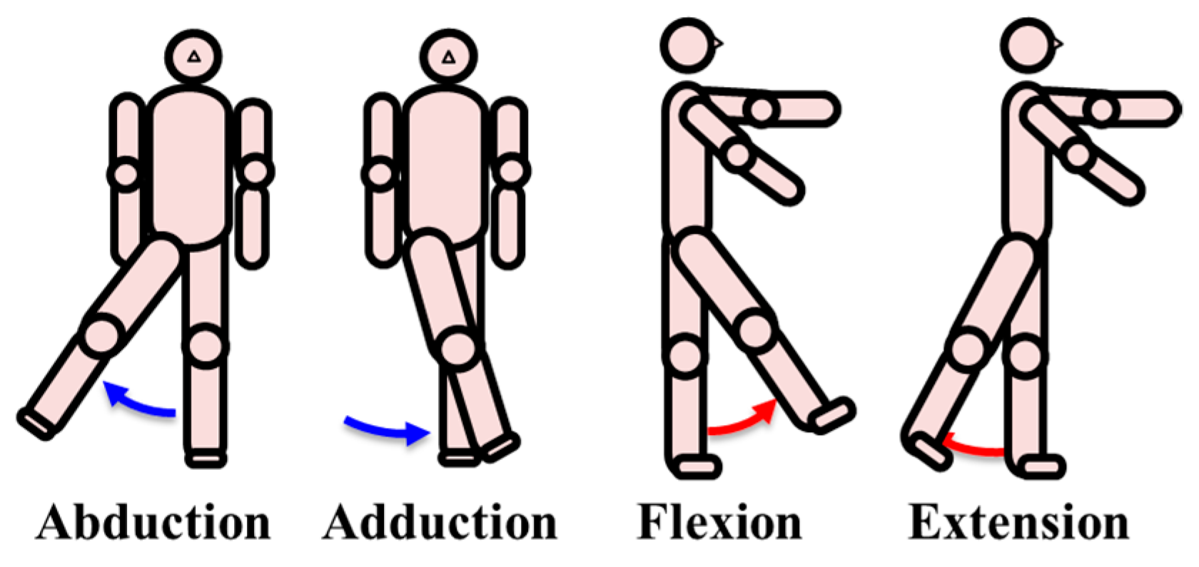
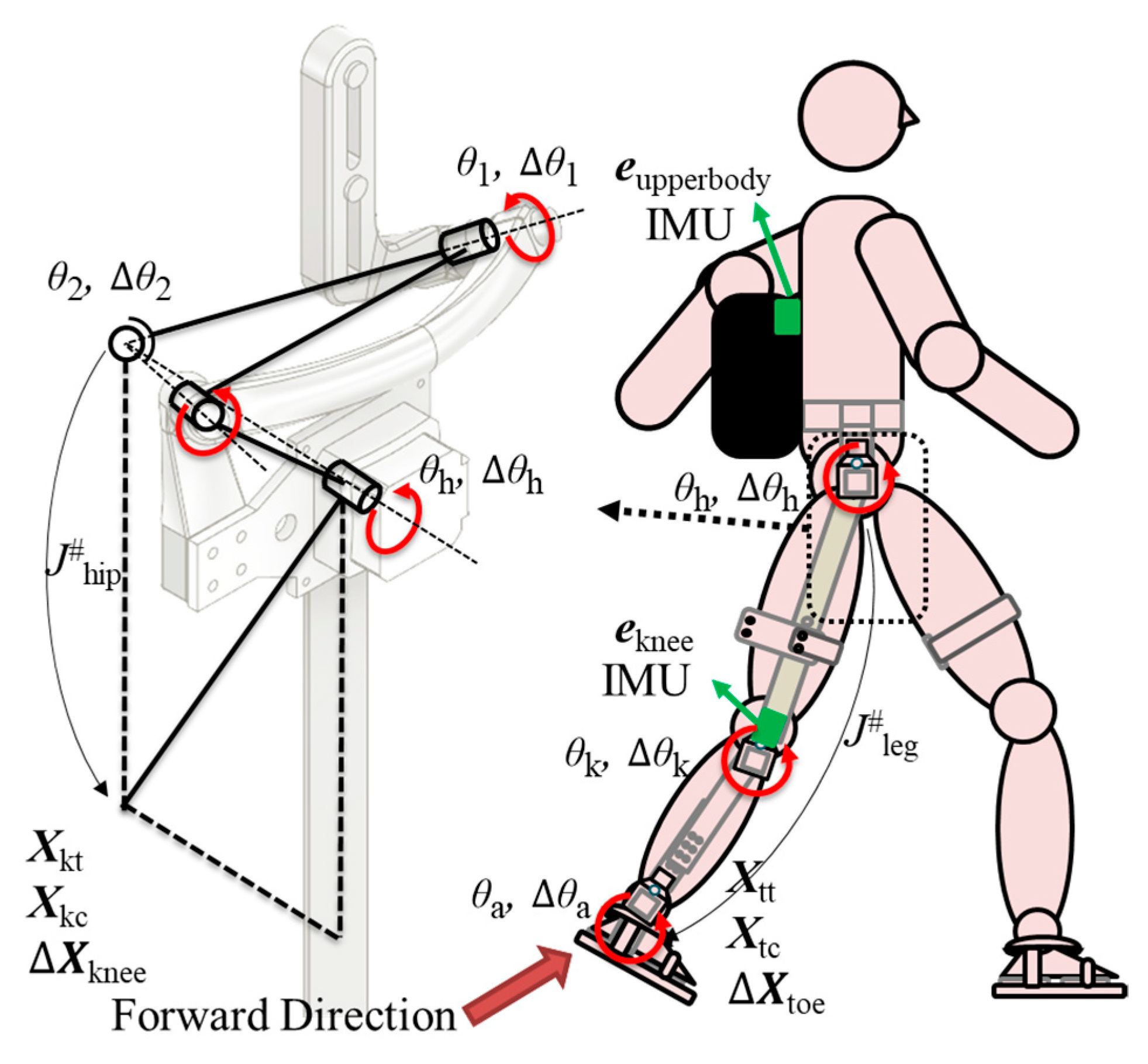
2.1.2. Kinematics of the Structure

To calculate the direct kinematics, firstly a model needs to be set up. The model is shown in Figure 6. Where C0, C1, C2, C3, and Ch are coordinate systems attached to the base, joints 1, 2, 3, and the tip; c1, c2, and c3 are rotation axes of joints 1, 2, and 3; θ1, θ2, and θh are joint 1, 2, and 3’s rotation angles; l01 is the distance between O0 and O1; l12 is the distance between O1 and O2; l23 is the distance between O2 and O3; l3h is the distance between O3 and Oh.
By calculating the linear transform matrix A C h C 0 from the base to the tip as is shown in Equation (1), the posture and the position of the tip can be obtained, which will be used for controlling the robot. To calculate the linear transformation matrix from the base to the tip, firstly the matrix between the neighboring joints needs to be calculated. Then, by multiplying one by one to connect them, the linear transformation matrix from the base to the tip can be derived.
A C h C 0 = A C 1 C 0 A C 2 C 1 A C 3 C 2 A C h C 3 R 4 × 4 ,
where A C h C 0 , A C 1 C 0 , A C 2 C 1 , A C 3 C 2 , and A C h C 3 are the linear transformation matrices from the coordinate system C0 to Ch, C0 to C1, C1 to C2, C2 to C3, and C3 to Ch, respectively, as expressed in Equations (2)–(5).
A C 1 C 0 = [ R ( c 1 , θ 1 ) p C 1 C 0 0 0 0 1 ] R 4 × 4 ,
A C 2 C 1 = [ R ( c 2 , θ 2 ) p C 2 C 1 0 0 0 1 ] R 4 × 4 ,
A C 3 C 2 = [ R ( y 3 , θ h ) p C 3 C 2 0 0 0 1 ] R 4 × 4 ,
A C h C 3 = [ I p C h C 3 0 0 0 1 ] R 4 × 4 ,
where R(c1, θ1) and R(c2, θ2) are the rotation matrices around the joint’s rotation axis c1 and c2 (considered as arbitrary axes), R(y3, θh) is the rotation matrix around the joint’s rotation axis c3 (c3 is coincident with y3), and p C 1 C 0 , p C 2 C 1 , p C 3 C 2 , and p C h C 3 are position vectors from C0 to C1, C1 to C2, C2 to C3, and C3 to Ch, respectively. The position vectors can be easily derived as the geometrical parameters of the structure are defined, and the rotation matrices can be expressed as Equations (6)–(8).
R ( c 1 , θ 1 ) = I cos θ 1 + ( 1 cos θ 1 ) c 1 c 1 T + sin θ 1 S ( c 1 ) R 3 × 3 ,
R ( c 2 , θ 2 ) = I cos θ 2 + ( 1 cos θ 2 ) c 2 c 2 T + sin θ 2 S ( c 2 ) R 3 × 3 ,
R ( y 3 , θ h ) = [ cos θ h 0 sin θ h 0 1 0 sin θ h 0 cos θ h ] R 3 × 3 ,
where S(c) is skew symmetric matrix, as is shown in Equation (9).
S ( c ) = [ 0 c z c y c z 0 c x c y c x 0 ] R 3 × 3
Then, the linear transform matrix A C h C 0 from the base to the tip is shown in Equation (10).
A C h C 0 = [ R C h C 0 p C h C 0 0 0 0 1 ] R 4 × 4
The posture of the tip can be expressed by R C h C 0 , and the position of the tip can be expressed by p C h C 0 , and they can be obtained from Equation (10). By inputting each joint’s angle and using Equation (10), the posture and the position of the tip can be calculated, which is utilized and explained in detail in Section 3.

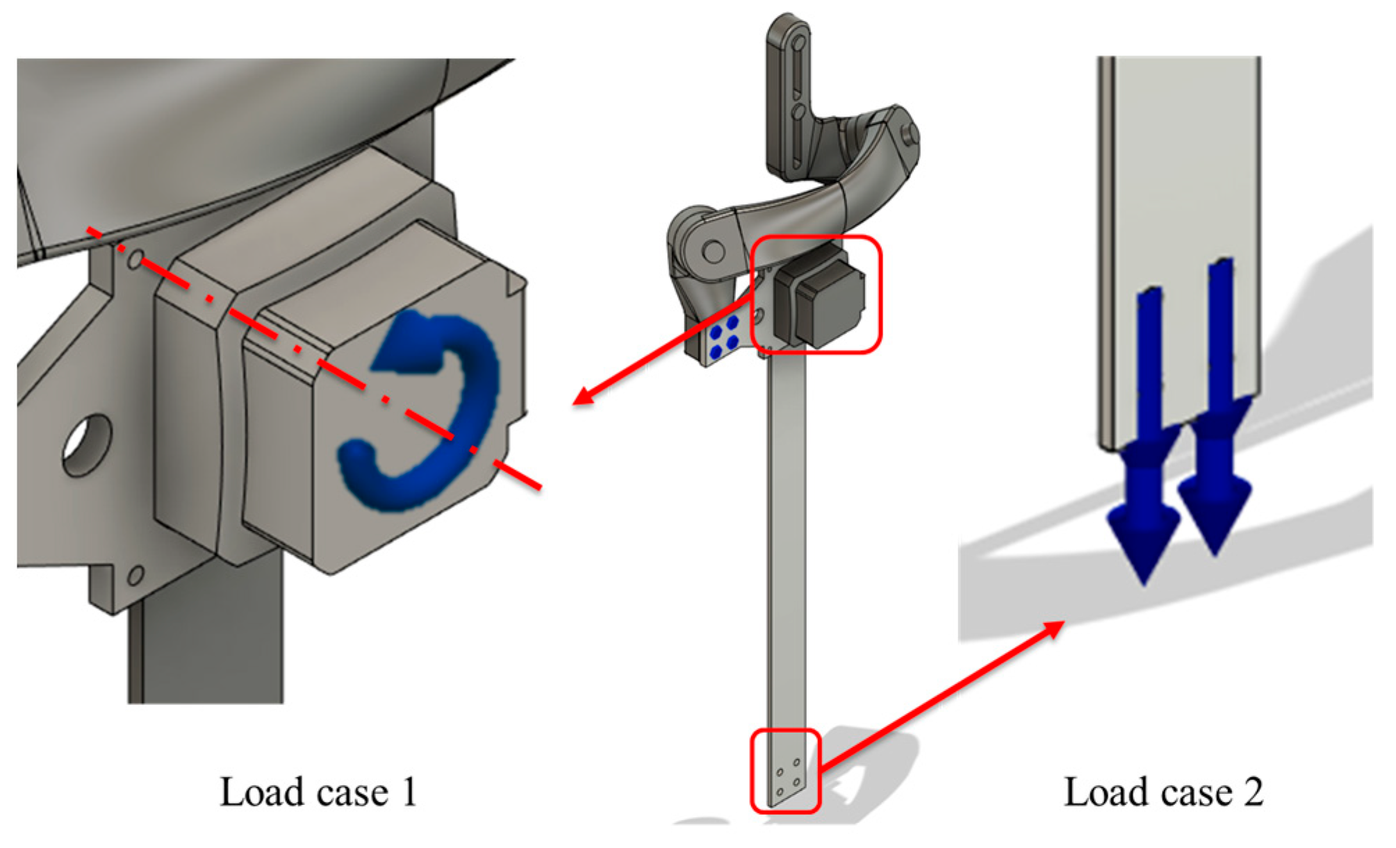
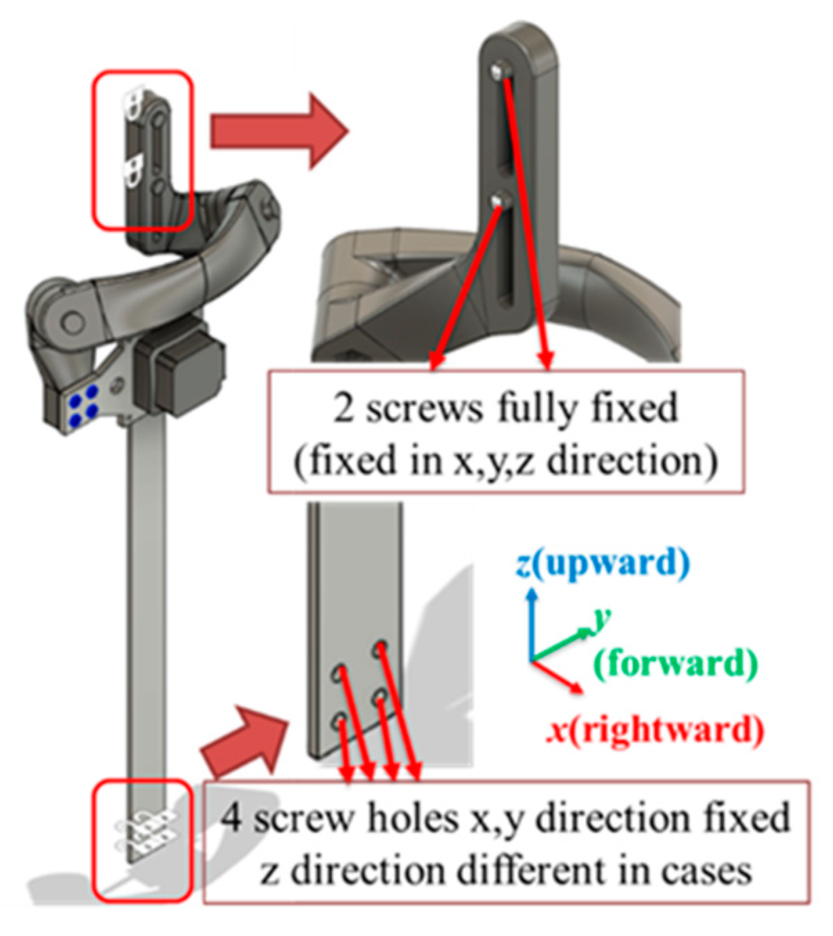
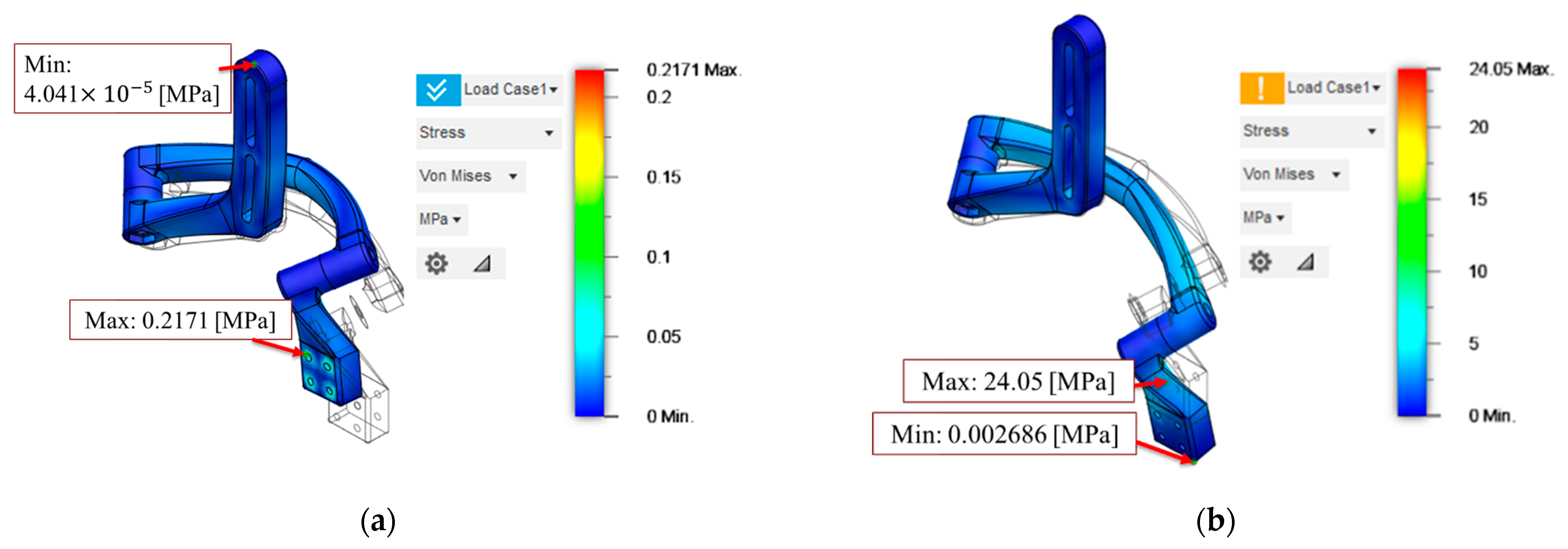
2.1.3. Simulation and Shape Design

After the structure is designed, before prototyping, it is important to ensure the structure is safe under certain load conditions. In this research, FEA (finite element analysis) is used to simulate the structure’s behavior under specific load conditions. Fusion 360 (2.0.18477 x86_64) is used, which is software from the Autodesk Company.
A 3D model of the structure that needs to be analyzed is created. As is shown in Figure 7, five models with different joint outer diameters from 20 [mm] to 40 [mm] have been prepared for the simulation.
In this simulation, two kinds of loads are specified, which are ‘force’ and ‘moment’, and there are two load cases (as shown in Figure 8) that consider force and moment, respectively. Study 1 (load case 1) is the simulation about when the motor generates power, and the structure that is connected to the motor receives force and reaction force. The study 2 (load case 2) is the simulation about when the lower part of the design is being pulled, which might be caused by the device’s gravity or the force generated by the user.
The magnitude of the moment is 19 [Nm], the same as the real case. The maximum moment of the hip joint in different motions is 95 [Nm] in walking [19], 34 [Nm] in standing up and sitting down [20], and 90 [Nm] in going up and down stairs [21]. In our lab experience, setting the assist ratio as 10% is already enough. Consequently, the maximum assist ratio is set as 20%, considering the safety factor. By calculating the highest maximum moment (walking) with the assist ratio as 20%, the required moment for the motor is 19 [Nm], and this number is used as the magnitude of the moment in study 1. The magnitude of the force is 400 [N] in study 2, which is about half of the gravity that an adult will receive (assuming the body weight of an adult is 80 [kg]).
The constraints of the model are set as shown in Figure 9. For both study 1 and study 2, the upper part of the structure that connects to the human body is set as fully fixed. The lower part of the structure that connects to the human’s thigh is set differently in different studies. For study 1 it is set as fully fixed; however, since study 2 will cause a displacement in the z direction, the constraint on the lower part in case 2 is set fixed in the x and y directions and free in the z direction in order to allow the displacement in the z direction to happen.
The simulation result is summarized in Table 1, and Figure 10 shows the contour map of the stress result for studies 1 and 2, respectively, as an example. The material stress limits are represented as the material yield strength or ultimate tensile strength. By choosing yield strength as the maximum strength of the material (46.53 [MPa] for 3D-printed PLA [22]) and Von Mises stress as the actual stress, the safety factor can be calculated. Since the simulated structure’s working condition is relatively complex and might receive heavier loads, 5 is chosen as the minimum safety factor in this research. Hence, considering the safety factor obtained from study 2, the model with 35 [mm] and 40 [mm] joint diameter can satisfy the requirements, and the other models are not strong enough for the requirements. The ROM of the model is obtained by collision checking. The moveable range of the structure and human are listed in Table 2. The mainly considered moveable range is hip joint abduction/adduction and flexion/extension, which is shown in Figure 11. The abduction angles of the 35 [mm] type and 40 [mm] type are 12.14 [deg] and 10.94 [deg], respectively. Since the 40 [mm] type cannot satisfy the ROM of abduction (which requires 12 [deg] [23]), the 35 [mm] type is chosen to be the final selected model.
The real prototype was made by a 3D printer. The 3D printer we used is the MF-2500EPⅡ by Mutoh company from Japan, and the filament we used is PolyMaxTMPC by Polymaker company from Japan. We currently use 3D printing and do not use metal because the metal is too heavy compared to the 3D-printed material. Also, the design’s shape is relatively complex, which might cause high production and maintenance costs. In the future, we will consider cost-effective manufacturing methods like injection modeling to lose weight while keeping the manufacturing price reasonable.

2.2. Control Method

As the new hip joint structure is attached, the rotation speed of the hip joint motor needs to be compensated. This is because the hip joint abduction/adduction and internal/external rotation are now included in this new structure, which requires the rotation of the hip joint motor. The key point of the compensation is to know the relative position between the upper body and the lower limb, which can be accomplished by using an IMU (inertial measurement unit). The basic procedure is to obtain the knee’s trajectory by analyzing IMUs’ data, then use the inverse kinematics to calculate how many angles the motor needs to rotate.
Before introducing the details of the controlling method, the parameters need to be clearly defined. Figure 12 shows the parameters used in the controlling process. Where Xtt is the toe’s target trajectory, Xtc is the toe’s current trajectory, Xkt is the knee’s target trajectory, and Xkc is the knee’s current trajectory. ΔXtoe and ΔXknee are derivations of trajectory, which is also the speed of the tip. θleg and Δθleg are the hip/knee/ankle joint’s rotation angle and speed. θhip and Δθhip are the hip structure joint’s rotation angle and speed. Eupperbody and eknee are Euler angles read by upper and lower IMUs. The IMU is attached to the knee joint and the control box, as shown in Figure 12; the green block represents the IMU.
To make the definition clearer to understand, Table 3 shows the size and contents of each vector.

2.2.1. Process of IMUs’ Data

The target of using IMU is to obtain the knee’s trajectory viewed from the user’s upper body. By reading IMU’s provided Euler angles, eupperbody and eknee, the rotation matrix from the upper body and knee to the world frame can be calculated as Equations (11) and (12).
R u w = R ( z ,   Ψ u )   R ( y ,   ϴ u )   R ( x ,   Φ u ) R 3 × 3 ,
R k w = R ( z ,   Ψ k )   R ( y ,   ϴ k )   R ( x ,   Φ k ) R 3 × 3 ,
where wRu is the rotation matrix from the world frame to the upper body, wRk is the rotation matrix from the world frame to the knee, Rx is the rotation matrix that rotates around the x-axis, Ry is the rotation matrix that rotates around the y-axis, Rz is the rotation matrix that rotates around the z-axis, Ψu, ϴu, and Φu are the pitch, yaw, and roll angles of the IMU on the upper body, and Ψk, ϴk, and Φk is the pitch, yaw, and roll angles of the IMU on the knee.
Then, the rotation matrix from the upper body to the knee, uRk can be calculated as Equations (13) and (14).
R u w R k u = R k w R 3 × 3 .
R k u = R u 1 w R k w R 3 × 3 .
Then, the knee’s position can be calculated by Equation (15).
p k u = R k u p 0 R 3 × 1 .
Then, the knee’s trajectory can be expressed by the linear transformation matrix uAk (from upper body to knee), as is shown in Equation (16).
A k u = [ R k u p k u 0 0 0 1 ] R 4 × 4 .

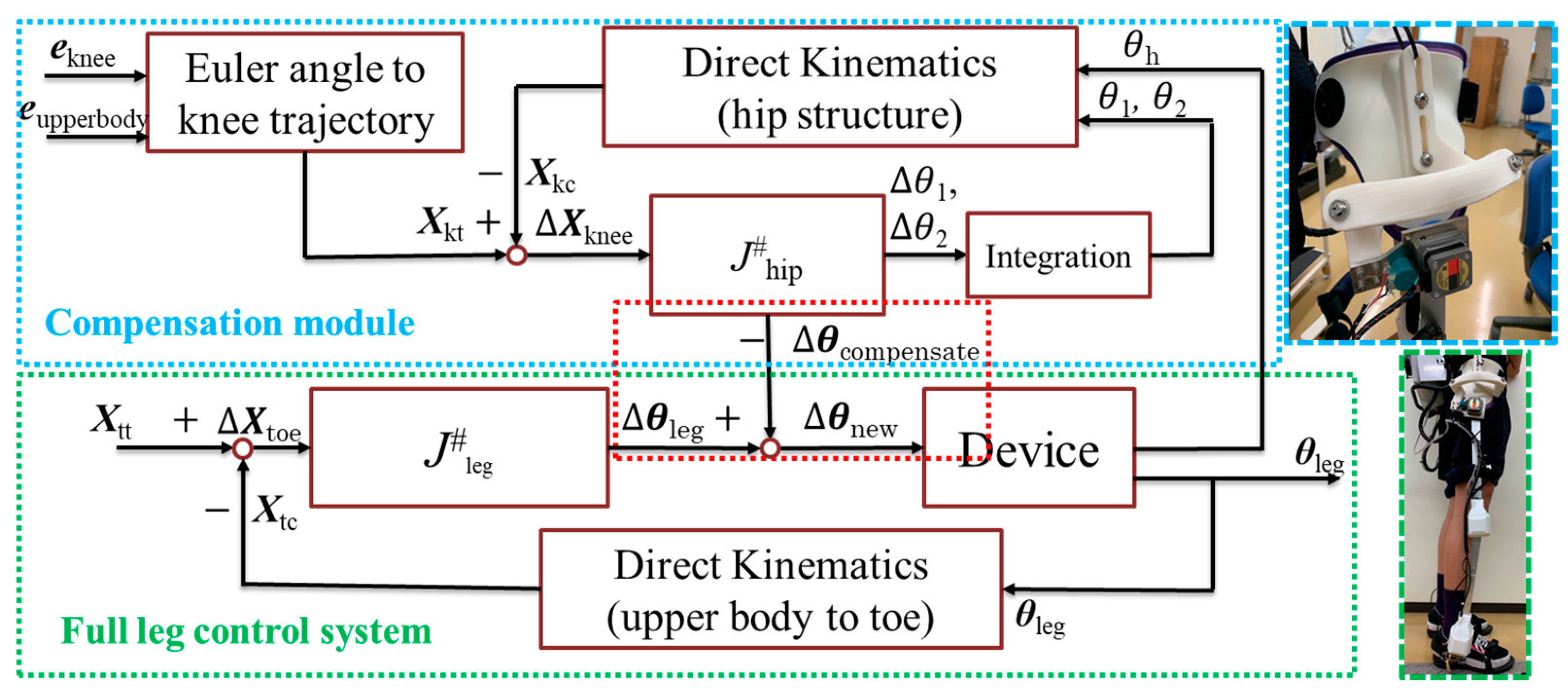
2.2.2. Control Method of Walking Assistance

Figure 13 shows the block diagram of the control system. The parts in the green rectangle are the full leg control system, and the parts in the blue rectangle are the compensation module.
The full leg control system is controlled by inputting the walking trajectory of the toe [13]. The preset toe’s trajectory during a walking cycle is used as the target trajectory as an input and to compare with the current toe’s trajectory. Without considering the newly proposed hip joint structure, in the green rectangle, the motor’s speed Δθleg is calculated by using the derivation of the toe’s trajectory ΔXtoe that obtained by comparing the current and target toe trajectory Xtc and Xtt, as is shown in Equations (17) and (18).
Δ X toe = X tt X tc ,
Δ θ leg = J leg # Δ X toe ,
where J leg # ∈ R6×3 is the general inverse of the Jacobian matrix (right inverse) of the whole leg structure (from hip to toe), and it can be obtained using Equation (19).
J leg # = J leg T ( J leg J leg T ) 1 ,
where J leg is the Jacobian matrix of the whole leg structure, as is shown in Equation (20).
J leg = [ x 3 × p C t C 3 x knee × p C t C k x ankle × p C t C a x 3 x knee x ankle ] R 6 × 3 ,
where x3 is the rotation axis of the motor attached to the hip joint, as is shown in Figure 6, Ck, Ca, and Ct are coordinate systems attached to the knee joint, ankle joint, and toe, respectively, and xknee and xankle are the rotation axes of the motors attached to the knee joint and ankle joint, respectively (Ck, Ca, Ct, xknee, and xankle are not shown in the figure).
By commanding the motor with its target speed, the motor will rotate to arrive at the target position. Up to now, the device can be controlled without considering the influence of introducing the new hip joint structure.
Since we have introduced the new hip joint structure into the system, we need to compensate the hip joint’s rotation angle to react to the extra motions (hip joint abduction/adduction and flexion/extension, as is shown in Figure 11) that come along with the new structure, and this is accomplished by using the compensation module.
In the blue rectangle (compensation module), firstly, by reading the IMUs’ data, the target trajectory of knee Xkt can be obtained. By comparing to the current knee trajectory Xkc as is shown in Equation (21), the derivation value of the knee’s trajectory ΔXknee can be obtained.
ΔXknee = XktXkc.
Then, by using the derivation value of the knee’s trajectory, the hip structure’s joint speed Δθhip can be obtained, as is shown in Equation (22).
Δ θ knee = J hip # Δ X knee ,
where J hip # is the general inverse of the Jacobian matrix (right inverse) of the hip structure, and it can be obtained using Equation (23).
J hip # = J hip T ( J hip J hip T ) 1 ,
where J hip is the Jacobian matrix of the hip structure, as is shown in Equation (24).
J hip = [ c 1 × p C h C 1 c 2 × p C h C 2 x 3 × p C h C 3 c 1 c 2 x 3 ] R 6 × 3
By building a compensation vector Δθcompensate = { θ h 0 0 } T and using the relationship shown in Equation (25), the hip joint’s motor’s rotation speed can be compensated.
Δ θ new = Δ θ leg Δ θ compensate
Then, after controlling the device and integrating the derivation value of the joint speed, the hip joint structure’s joint angle θhip can be obtained, and through direct kinematics as is shown in Equation (10), the new current trajectory of the knee Xkc can be calculated using the rotational matrix R C h C 0 and position vector p C h C 0 in the linear transformation matrix A C h C 0 and compared with the target trajectory again.
After compensation, the new target speed of each motor, Δθnew, is transferred to the motor driver to drive the motor. After the motor rotated, by reading the potentiometer’s value, the new current angle of each motor can be obtained, and through direct kinematics, the current toe trajectory can be calculated and compared with the target again.

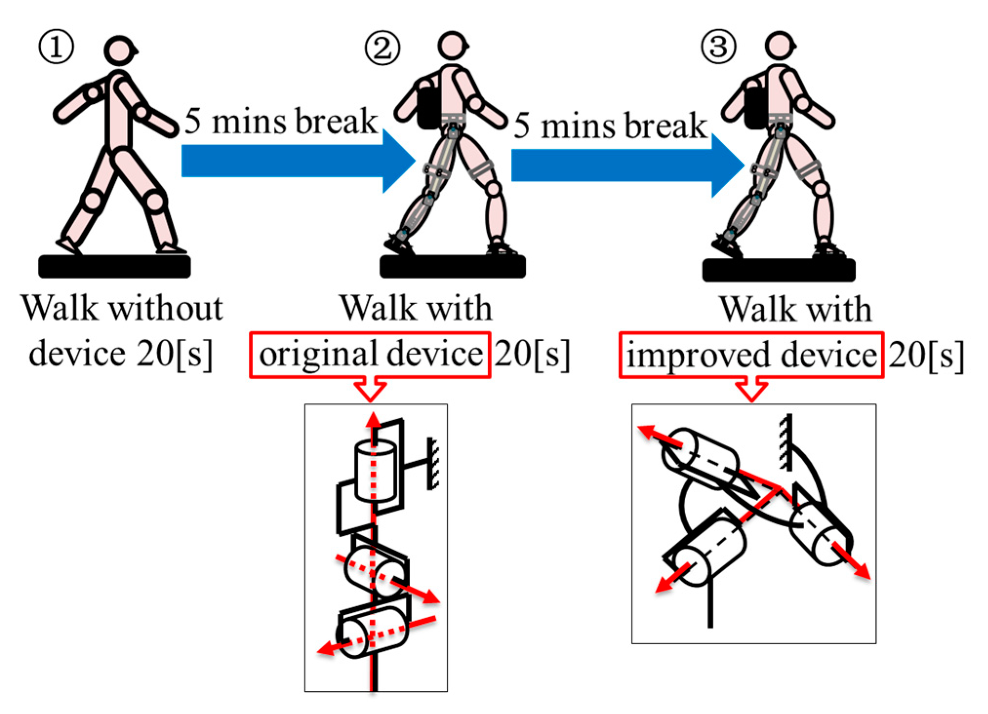
2.3. Experiment Method

Motion capture is a technique used to record the movement of joints during various actions such as walking, standing up, and sitting down. The motion capture system utilized is called ‘Kinema Tracer Motion Capture’. The system described is an advanced 3D motion analysis system specifically designed for professional use. It operates as a marker-type motion capture system, utilizing CCD cameras to record images and identify colored markers placed on the body’s joints. This enables the system to capture and analyze the three-dimensional movement of the human body accurately. The recording frequency is 30 frames in 1 s. The resulting data consists of the trajectory points in XYZ coordinates for each frame of a video.
A total of 6 participants joined the experiment, and their weight and height data are shown in Table 4. Even though this research’s target is to support the elderly in their daily lives and rehabilitation process, as a first step to check the restriction caused by the mismatched hip joint structure, young people have a bigger motion range compared to the elderly, which allows the result to be more obvious. The restriction mentioned above would affect all participants and is not related to the age of participants. In the future, real elderly participants will be invited to join our experiments to obtain further data closer to the real using condition.
Participants are required to walk on the treadmill for 20 s for 3 times, in which the first time is walking without device, the second time is walking with the original device, and the third time is walking with the improved device. The experiment’s procedure and utilized devices were shown in Figure 14. All 6 participants’ experiment orders are the same (firstly testing without a device, then with the original device, and lastly with an improved device). We arrange the experiment order targeting achieving non-influenced results. To diminish the influence of the order, all participants were trained on how to walk with the device, and during each experiment, participants took a long rest (15 min) to make sure their muscles could be fully or almost fully recovered. To make sure the recorded data are stable, we required the participants to start walking earlier and stop later than we start and stop recording (10 s earlier and 5 s later). Even though the participant’s muscle tiredness is influencing the experiment result, such order arrangement can make the influence the smallest. Without the device, experiments are performed first as a standard and reference for the other two groups. The original device experiments are performed before the improved device experiments for more convincing results because if we do the contrary, the restriction of the original device to the moving angles can be doubted (the restricted angle might not be because of the device but due to the tiredness). The original device is the lower limb exoskeleton developed by our team, as shown in Figure 1, which has the kinematic and biologically mismatched hip joint structure. The improved device is the original device equipped with a newly developed hip joint structure, as is shown in Figure 4. A metronome is used to help the participants to keep a stable cadence. A treadmill is set at the same speed (1.8 [km/h]) for all 6 participants. By controlling the variables, the result can show the influence of the device. The cadence of participants 1, 2, 3, 4, 5, and 6 is 63, 70, 50, 70, 60, and 64.
During the walking cycle, the movement of the hip is not simply rotating around only 1 axis. The hip will have extension/flexion, adduction/abduction, and internal/external rotation. In this experiment, hip joint flexion/extension and adduction/abduction (these two motions are as shown in Figure 11) are measured. During walking, the internal/external rotation is also needed. Compared to other angles, the internal/external rotation angle is relatively small during straight walking and bigger in turning. At the beginning, we prepared the experiments for only walking straight, so we check the extension/flexion and adduction/abduction angles first. At the beginning of one walking cycle, when the foot contacts the ground, the biggest hip joint flexion occurs. In the late stance of the stance phase, the foot is about to leave the ground, and this is when the biggest hip joint extension occurs. After that, at the end of the swinging phase, when the foot contacts the ground again, the hip joint flexion will be at its maximum value again.

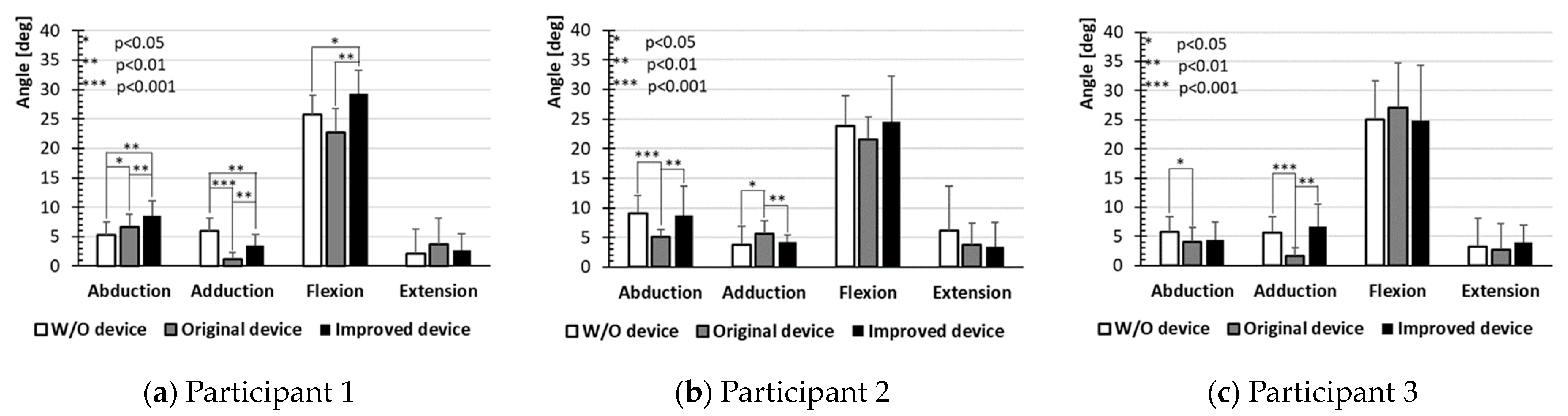
3. Results and Discussion

For each participant’s data, the mean values of the maximum abduction, adduction, flexion, and extension angles of each walking cycle are shown in Figure 15. The results include the joint angle data without the device, with the original device, and with the improved device. The result that is without a device is for reference. Because of the original device’s misalignment of the kinematic and biological joints, the hip joint abduction/adduction is restricted. By changing to the improved device, this kind of restriction will no longer occur, which will allow the device to provide more natural gait guidance. By comparing the joint’s mean value of abduction/adduction’s max value in each walking cycle, the effectiveness of the device can be evaluated. By performing the T-test, the result shows a relatively strong constraint of the tendency. For the hip joint flexion/extension, because the device is helping the participants to walk, it is theoretically expected to have a slight increase. The motion angle of the participants has a possibility to expand because if the participants’ motion were instructed by a robot, their motion would be activated unconsciously. This can be found in the previous research. Also, since the original device’s hip joint structure has restrictions to the hip joint adduction/abduction and internal/external rotation, when these two motions are restricted, the hip joint flexion/extension might also be influenced to some degree. Since the walking speed is set the same for all 6 participants (1.8 [km/h] set on the treadmill), and the cadence is set the same by using a metronome, theoretically the motion should also be the same. However, since the device will make an influence on the participants’ motion, it is impossible to keep the exact same cadence for each participant (when walking speed is set and secured by using a treadmill). This indicates that the metronome performs the role of a guide for keeping the cadence, but there would be slight differences for each participant’s cadence for sure. By recording and comparing each motion’s angle difference, the effects of the devices can be studied. Also, by hearing the comments from the participants, the device is more comfortable to use.
The analysis of Figure 15 is as follows: In most cases, the improved device shows a slightly higher or comparable abduction angle compared to the original device. Participants 1, 2, and 5 show statistically significant increases in abduction angle with the improved device compared to the original device condition. Across participants, there is generally less improvement in adduction angle with the improved device, and differences between conditions are less pronounced than in abduction. For some participants, such as participants 1 and 3, the adduction angle is increased with the improved device, but if also considering other participants, this increase is minor compared to abduction and flexion. Flexion shows an increase with the improved device across participants. For instance, participants 1, 4, and 6 demonstrate significant improvements in hip flexion angle when using the improved device compared to the original device conditions. For most participants, extension angles remain relatively low across all conditions.
The experiment result can also be analyzed by considering the combination of the movements and setting groups as the abduction/adduction group and flexion/extension group. By adding the data in each group together, we can consider abduction angle plus adduction angle as group 1 and flexion angle plus extension angle as group 2, as shown in Equations (26) and (27). And the ratio can be considered as the percentage of a certain movement angle in a certain group. The ratio can reflect the change tendency of the participants.
Group 1 = abduction angle + adduction angle.
Group 2 = flexion angle + extension angle.
Figure 16 shows the result of the combined group. In Group 1, most participants show a significant increase in the range of abduction/adduction when using the improved device compared to the original device, as seen in participants 1, 3, 4, and 6, which suggests that the improved device better accommodates lateral movements. In Group 2, the range of flexion/extension is significantly higher with the improved device compared to the original device across all participants. This is especially obvious for participants 1 and 4 with statistical significance. Overall, the improved device significantly enhances both Group 1 (abduction/adduction) and Group 2 (flexion/extension) angles. The improved abduction/adduction range in Group 1 indicates additional stability benefits, which provides users with a more natural and stable walking experience. These results show the benefits of the kinematic–biologically structured exoskeleton, which allows the exoskeleton to better match natural hip biomechanics.
By summarizing the mean value of all participants (age from 23 to 25 [years old], height from 170 to 180 [cm], weight from 58 to 100 [kg], cadence from 50 to 70, under the speed of 1.8 [km/h]), and calculating the change rate compared to without device data of abduction/adduction and flexion/extension angle, Figure 17 can be obtained. In which, Figure 17a,c can be understood as a summary of Figure 15 and Figure 17b,d can be considered as a summary of Figure 16. Comparing to Figure 15 and Figure 16, after summarizing all 6 participants’ data, the tendency of the data is clearer to be observed. From the figure, it is clear to see that compared to the original device, the angle with each motion with the improved device is 23.0%, 24.8%, 8.7%, and 12.5% larger than compared with the original device, respectively. Since the normal range of the abduction/adduction angle is not a significant number, the change in the number is also not so big, and this is the reason why we also choose the percentage data to express the experiment result. Similarly, it is clear to see that group 1 (abduction + adduction) and group 2 (flexion + extension) are 23.6% and 9.3% larger than compared with the original device. The positive result shows the improved device can diminish the mismatch problem. The abduction and adduction angles are increased because the restriction of the robot’s and human’s hip joint rotational axes misalignment has been significantly improved.
These results show that the newly designed hip joint structure allows the hip to move freely and improves the hip joint’s posture during walking by eliminating the mismatch between the robot and human hip.

4. Conclusions

This research aims to develop a new kinematic–biologically matched hip joint structure for a full-leg exoskeleton. The human hip joint has 3 DOFs, allowing movements such as flexion/extension, adduction/abduction, and internal/external rotation. To provide the exoskeleton’s hip joint with 3 DOFs in a kinematic–biologically matched condition, a novel hip structure with tilt axes is proposed.
Before building the prototype, force analysis is performed to select the suitable shape (outer diameter of the joint) of the links. The safety factor and ROM are considered, and finally, a model is chosen and built. Once the new hip joint structure is integrated, a crucial aspect is the real-time adjustment of the motor’s output to match the hip joint’s posture. This adjustment is achieved through the use of IMUs to measure the user’s hip posture, allowing for the calculation of the motor’s output angle using inverse kinematics.
To evaluate the effectiveness of the device, motion capture experiments were conducted involving 6 participants walking on a treadmill under three conditions: without the device, with the original device, and with the improved device. By comparing the angles of hip joint movement across these conditions, the study substantiates the effectiveness of the improved exoskeleton device in improving hip joint mobility and function (increasing the abduction and adduction angle by 23.0% and 24.8%). Since in our experiments, all the participants are young adults, we will invite real elderly to join our experiment as a future work.

Author Contributions

Conceptualization, E.T. and Y.W.; kinematics, E.T. and Y.W.; simulation, S.Y.; hardware, Y.W., Y.F. and X.W.; validation, K.O., K.N. and E.T.; All authors have read and agreed to the published version of the manuscript.

Funding

This research was funded by JSPS KAKENHI (Grant Number JP23K25251) and the China Scholarship Council (grant number 202308050133).

Data Availability Statement

The original contributions presented in the study are included in the article, further inquiries can be directed to the corresponding authors upon reasonable request.

Conflicts of Interest

The authors declare no conflicts of interest.

References

  1. Wall, A.; Borg, J.; Vreede, K.; Palmcrantz, S. A randomized controlled study incorporating an electromechanical gait machine, the Hybrid Assistive Limb, in gait training of patients with severe limitations in walking in the subacute phase after stroke. PLoS ONE 2020, 15, e0229707. [Google Scholar] [CrossRef] [PubMed]
  2. Esquenazi, A.; Talaty, M.; Packel, A.; Saulino, M. The Rewalk powered exoskeleton to restore ambulatory function to individuals with thoracic-level motor-complete spinal cord injury. Am. J. Phys. Med. Rehabil. 2012, 91, 911–921. [Google Scholar] [CrossRef]
  3. Wu, J.; Gao, J.; Song, R.; Li, R.; Li, Y.; Jiang, L. The design and control of a 3DOF lower limb rehabilitation robot. Mechatronics 2016, 33, 13–22. [Google Scholar] [CrossRef]
  4. Rose, L.; Bazzocchi, M.C.F.; de Souza, C.; Vaughan-Graham, J.; Patterson, K.; Nejat, G. A framework for mapping and controlling exoskeleton gait patterns in both simulation and real-world. In Proceedings of the 2020 Design of Medical Devices Conference, (DMD2020), DMD2020-9009, Minneapolis, MN, USA, 6–9 April 2020. [Google Scholar]
  5. Sarajchi, M.; Sirlantzis, K. Pediatric Robotic Lower-Limb Exoskeleton: An Innovative Design and Kinematic Analysis. IEEE Access 2023, 11, 115219–115230. [Google Scholar] [CrossRef]
  6. Zhang, T.; Tran, M.; Huang, H.H. NREL-Exo: A 4-DoFs wearable hip exoskeleton for walking and balance assistance in locomotion. In Proceedings of the IEEE International Conference on Intelligent Robots and Systems (IROS2017), Vancouver, BC, Canada, 24–28 September 2017; pp. 508–513. [Google Scholar]
  7. Guzmán-Valdivia, C.H.; Blanco-Ortega, A.; Oliver-Salazar, M.A.; Gómez-Becerra, F.A.; Carrera-Escobedo, J.L. HipBot—The design, development and control of a therapeutic robot for hip rehabilitation. Mechatronics 2015, 30, 55–64. [Google Scholar] [CrossRef]
  8. Yasuhara, K.; Shimada, K.; Koyama, T.; Ido, T.; Kikuchi, K.; Endo, Y. Walking Assist Device with Stride Management System. Honda R&D Tech. Rev. 2009, 21, 57–66. [Google Scholar]
  9. Sadeqi, S.; Bourgeois, S.P.; Park, E.J.; Arzanpour, S. Design and performance analysis of a 3-RRR spherical parallel manipulator for hip exoskeleton applications. J. Rehabil. Assist. Technol. Eng. 2017, 4, 1–11. [Google Scholar] [CrossRef]
  10. Yusa, H.; Tanaka, E.; Ikehara, T.; Ito, K.; Saegusa, S.; Hashimoto, K.; Sato, Y.; Yuge, L. Development of a walking assistance apparatus using a spatial parallel link mechanism and evaluation of muscle activity. In Proceedings of the 19th IEEE International Symposium in Robot and Human Interactive Communication (IEEE Ro-Man 2010), Viareggio, Italy, 13–15 September 2010; pp. 151–158. [Google Scholar]
  11. Tanaka, E.; Saegusa, S.; Yuge, L. Development of a Whole Body Motion Support Type Mobile Suit and Evaluation of Cerebral Activity Corresponding to the Cortical Motor Areas. J. Adv. Mech. Des. Syst. Manuf. 2013, 7, 82–94. [Google Scholar] [CrossRef]
  12. Yang, B.R.; Lee, H.H.; Tanaka, E. Posture compensation of a walking assistive device using zero-moment point to stabilize motions on stairs. J. Adv. Mech. Des. Syst. Manuf. 2020, 14, 1–18. [Google Scholar] [CrossRef]
  13. Yang, B.R.; Zhang, Y.C.; Wang, H.T.; Yu, S.H.; Lee, H.H.; Tanaka, E. Automatic walking pattern transformation method of an assistive device during stair-ground transition. J. Adv. Mech. Des. Syst. Manuf. 2021, 15, 1–20. [Google Scholar] [CrossRef]
  14. Fang, Y.; Hou, B.; Wu, X.; Wang, Y.; Osawa, K.; Tanaka, E. A Stepper Motor-Powered Lower Limb Exoskeleton with Multiple Assistance Functions for Daily Use by the Elderly. J. Robot. Mechatron. 2023, 35, 601–611. [Google Scholar] [CrossRef]
  15. Tanaka, E.; Suzuki, T.; Saegusa, S.; Yuge, L. Walking assistance apparatus able to select the control method according to the purpose of the user. In Proceedings of the World Automation Congress, Waikoloa, HI, USA, 3–7 August 2014; pp. 537–542. [Google Scholar]
  16. Wang, Y.; Fang, Y.; Wu, X.; Osawa, K.; Tanaka, E. Development of a 3-DOF Kinematic-Biological Matched Hip Joint Structure for Lower Limb Exoskeleton. In Proceedings of the ICMDT2023, ThE1-1, Jeju Island, Republic of Korea, 8–11 March 2023; p. 65. [Google Scholar]
  17. Wang, Y.; Wu, X.; Fang, Y.; Osawa, K.; Nakagawa, K.; Yamasaki, S.; Eiichiro, T. Mechanical Design of a 3-DOF Kinematic-Biological matched Hip Joint Structure for Lower Limb Exoskeleton, Mechanism Design for Robotics. In MEDER 2024. Mechanisms and Machine Science; Springer: Cham, Switzerland, 2024; Volume 166. [Google Scholar]
  18. Wang, Y.; Wu, X.; Fang, Y.; Osawa, K.; Nakagawa, K.; Tanaka, E. Development of the Control Method of a 3-DOF KinematicBiological Matched Hip Joint Structure for Lower Limb Exoskeleton. In Proceedings of the ICARM 2024, Tokyo, Japan, 6–8 July 2024; pp. 13–18. [Google Scholar]
  19. Ehara, Y.; Yamamoto, S. Introduction to Body-Dynamics—Analysis of Gait and Gait Initiation; Ishiyaku Publishers, Inc.: Tokyo, Japan, 2002; p. 137. (In Japanese) [Google Scholar]
  20. Ehara, Y. Introduction to Body-Dynamics—Analysis of Standing up Movement; Ishiyaku Publishers, Inc.: Tokyo, Japan, 2001; p. 67. (In Japanese) [Google Scholar]
  21. Nakamura, R.; Saito, H.; Nagasaki, H. Fundamental Kinesiology; Ishiyaku Publishers, Inc.: Tokyo, Japan, 2003; pp. 403–405. (In Japanese) [Google Scholar]
  22. Rodríguez-Panes, A.; Claver, J.; Camacho, A.M. The influence of manufacturing parameters on the mechanical behavior of PLA and ABS pieces manufactured by FDM: A comparative analysis. Materials 2018, 11, 1333. [Google Scholar] [CrossRef] [PubMed]
  23. Hamill, J.; Knutzen, K.M.; Derrick, T.R. Biomechanical Basis of Human Movement, 5th ed.; Wolters Kluwer: Alphen aan den Rijn, The Netherlands, 2022; p. 184. [Google Scholar]
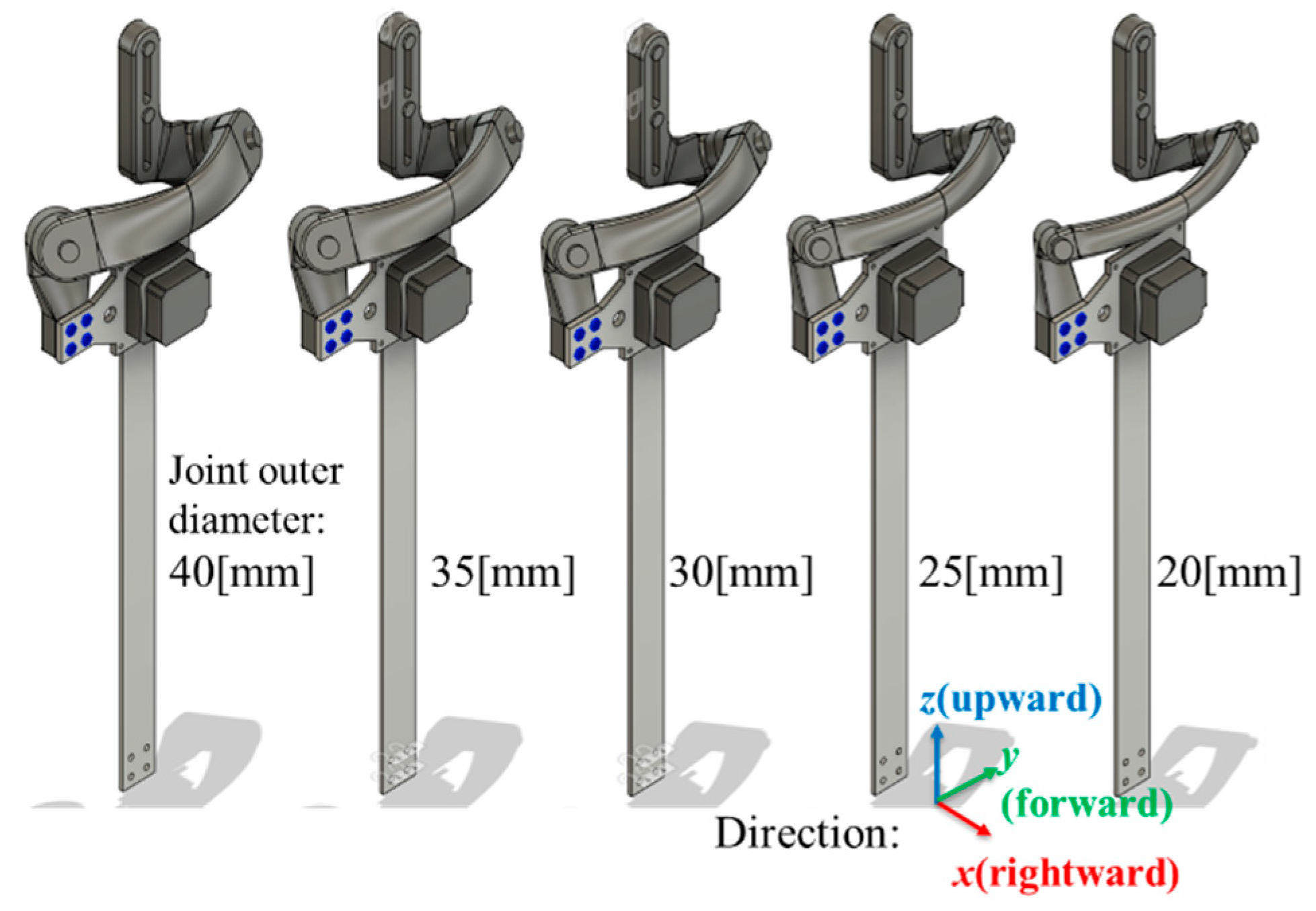
Figure 1. Previous research of our lab [13]: (a) signal flow and basic structure of the robot; (b) kinematic and biological mismatch of hip (for the right leg).
Machines 12 00924 g001
Figure 2. Example of kinematic and biological mismatch of hip (for the right leg).
Machines 12 00924 g002
Figure 3. Right leg hip joint structure of other studies (y-axis always points forward): (a) HAL [1]; (b) Honda’s device [7]; and (c) pediatric robotic lower limb exoskeleton [5].
Machines 12 00924 g003
Figure 4. Newly proposed hip joint structure (for the right leg).
Machines 12 00924 g004
Figure 5. 3 views of the structure (for the right leg).
Machines 12 00924 g005
Figure 6. Kinematic model of the structure (for the right leg).
Machines 12 00924 g006
Figure 7. Five models with different outer diameters (for the right leg).
Machines 12 00924 g007
Figure 8. 2 load cases (for the right leg).
Machines 12 00924 g008
Figure 9. Setting the suitable constraints (for the right leg).
Machines 12 00924 g009
Figure 10. Simulation results: (a) stress result of study 1 (20 [mm] type model as an example); (b) stress result of study 2 (20 [mm] type model as an example).
Machines 12 00924 g010
Figure 11. Hip joint abduction/adduction and flexion/extension.
Machines 12 00924 g011
Figure 12. Defining parameters that are used in calculation.
Machines 12 00924 g012
Figure 13. Control system of the hip joint structure and the whole leg.
Machines 12 00924 g013
Figure 14. Experiment procedure.
Machines 12 00924 g014
Figure 15. Participants’ mean value of the maximum abduction, adduction, flexion, and extension angles of each walking cycle: (a) Results of participant 1; (b) results of participant 2; (c) results of participant 3; (d) results of participant 4; (e) results of participant 5; and (f) results of participant 6.
Machines 12 00924 g015aMachines 12 00924 g015b
Figure 16. Participants’ mean value of the maximum abduction + adduction (group 1) and flexion + extension (group 2) angles of each walking cycle: (a) Results of participant 1; (b) results of participant 2; (c) results of participant 3; (d) results of participant 4; (e) results of participant 5; and (f) results of participant 6.
Machines 12 00924 g016aMachines 12 00924 g016b
Figure 17. Summarized results of all participants: (a) 6 participants’ mean value of the maximum abduction, adduction, flexion, and extension angles of each walking cycle; (b) 6 participants’ mean value of the maximum abduction + adduction and flexion + extension angles of each walking cycle; (c) 6 participants’ average each angle change rate based on without a device; (d) 6 participants’ average abduction + adduction (group 1) and flexion + extension (group 2) change rate based on without a device.
Machines 12 00924 g017aMachines 12 00924 g017b
Table 1. Simulation results.
Diameter20 [mm]25 [mm]30 [mm]35 [mm]40 [mm]
Study 1Max stress 0.217
[MPa]
0.205
[MPa]
0.192
[MPa]
0.110
[MPa]
0.105
[MPa]
Safety factor>10>10>10>10>10
Study 2Max stress24.05
[MPa]
13.32
[MPa]
12.89
[MPa]
8.99
[MPa]
8.762
[MPa]
Safety factor1.933.493.615.185.31
Table 2. Range of motion (ROM) of each model.
Range of Motion [deg]
Flexion/
Extension
Abduction/
Adduction
Diameter
[mm]
20+115.06/−60.07+14.55/−54.16
25+113.83/−60.07+13.74/−54.16
30+112.28/−60.07+12.88/−54.16
35+109.86/−60.07+12.14/−54.16
40+108.08/−60.07+10.94/−54.16
Human walking [23]+40/−15+12/−12
Table 3. Details of each vector.
VectorElementsMeaning
Xtt{xtt ytt ztt θxtt θytt θztt}Ttoe’s target trajectory
Xtc{xtc ytc ztc θxtc θytc θztc}Ttoe’s current trajectory
Xkt{xkt ykt zkt θxkt θykt θzkt}Tknee’s target trajectory
Xkc{xkc ykc zkc θxkc θykc θzkc}Tknee’s current trajectory
ΔXtoextoe Δytoe Δztoe Δθxtoe Δθytoe Δθztoe}Tderivation of toe’s trajectory
ΔXkneexknee Δyknee Δzknee Δθxknee Δθyknee Δθzknee}Tderivation of knee’s trajectory
θleg{θh θk θa}Thip/knee/ankle joint’s rotation angle
Δθlegθh Δθk Δθa}Thip/knee/ankle joint’s rotation speed
θhip{θ1 θ2 θh}Thip structure joint’s rotation angle
Δθhipθ1 Δθ2 Δθh}Thip structure joint’s rotation speed
eupperbody{Ψu ϴu Φu}TEuler angle read by upper IMU
eknee{Ψk ϴk Φk}TEuler angle read by lower IMU
Table 4. Participants’ physical data.
Participant123456
Height [cm]173170177180180178
Weight [kg]5860776310070
Age [years]252524242323
Body conditionAble-bodiedAble-bodiedAble-bodiedAble-bodiedAble-bodiedAble-bodied
Disclaimer/Publisher’s Note: The statements, opinions and data contained in all publications are solely those of the individual author(s) and contributor(s) and not of MDPI and/or the editor(s). MDPI and/or the editor(s) disclaim responsibility for any injury to people or property resulting from any ideas, methods, instructions or products referred to in the content.

