Article

Kinematic Analysis of a Cam-Follower-Type Transplanting Mechanism for a 1.54 kW Biodegradable Potted Cabbage Transplanter

1
Department of Agricultural Machinery Engineering, Graduate School, Chungnam National University, Daejeon 34134, Republic of Korea
2
Department of Smart Agricultural Systems, Graduate School, Chungnam National University, Daejeon 34134, Republic of Korea
3
HSM Co., Ltd., Cheonan 31246, Republic of Korea
*
Author to whom correspondence should be addressed.
Machines 2024, 12(12), 925; https://doi.org/10.3390/machines12120925
Submission received: 25 November 2024 / Revised: 13 December 2024 / Accepted: 14 December 2024 / Published: 17 December 2024
(This article belongs to the Section Machine Design and Theory)

Abstract

Widespread use of plastic seedling pots has been attributed to their light weight and durable characteristics. However, these pots have limitations in facilitating efficient root establishment. Recent studies indicate that biodegradable seedling pots not only enhance seedling resilience but are also environmentally sustainable through natural decomposition. This study presents a kinematic analysis of a cabbage transplanting mechanism specifically under development for biodegradable seedling pots, focusing on position, velocity, acceleration, and power. The optimization of link combinations within the transplanting mechanism was analyzed to enhance the transplantation process, focusing on achieving precise depth and spacing for potted seedlings. A kinematic model of the mechanism was developed and simulated using commercial mechanical design and simulation software, followed by validation through performance tests. The proposed transplanter comprised a four-bar-linkage mechanism consisting of a driving link, a driven link, a connecting link, and a guide bar. Simulation trials were conducted by varying the main arm link length while keeping machine forward speed and mechanism driving speed fixed. Results indicated that the optimal mechanism parameters included a driving link of 50 mm, a connecting arm of 120 mm, a guide bar of 120 mm, and an end-effector link of 220 mm. A dibbling hopper length of 153 mm was identified as the most effective for operation. With these recommended link lengths, validated velocities of the end hopper in the ‘X’ and ‘Y’ directions were 284 mm/s and 1379 mm/s, respectively, while corresponding accelerations were measured at 1241 mm/s2 and 8664 mm/s2. The driving power requirement was calculated to be 17.4 W. These findings suggest that the developed mechanism provides effective planting performance, evidenced by a high degree of seedling uprightness and minimal soil disturbance. This study supports the use of biodegradable pots in mechanized transplanting as a viable alternative to conventional plastic pots, with potential benefits for both agricultural efficiency and environmental sustainability.

1. Introduction

Cabbage (Brassica rapa L. ssp. Pekinensis) is grown extensively as a staple vegetable crop across many Asian countries, particularly in Korea and China, driven by the high demand for Kimchi, a staple of Korean cuisine [1]. In Korea, the autumn cabbage cultivation area declined by 5.7% from 13,953 ha in 2022 to 13,152 ha in 2023 [2]. As of 2022, approximately 63.3% upland farmland in Korea was managed with agricultural machinery [3]. During peak agricultural seasons, labor shortages commonly cause delays in the transplantation process, leading to elevated seedling mortality rates and lower overall crop yields [4,5]. To meet the rising global food demand, modern agriculture heavily relies on the extensive use of plastic products [6,7]. While plastic offers notable advantages in agricultural practices, studies have highlighted its adverse effects on soil fertility [8] and soil invertebrates [9,10]. Moreover, certain plastic materials may persist in the environment for up to 32 years [11]. In contrast, biodegradable materials decompose in soil [12], while pots protect roots and promote robust seedling growth for direct field transplantation [13].
For mechanized transplantation, two primary methods for seedling production include cultivation in plug trays [14] and biodegradable paper pots [15,16]. Transplanting from plastic trays can damage roots [17], while biodegradable trays allow intact transplantation, preserving root structure and enhancing growth [18].
In the international market, most potted vegetable transplanting machines use integrated mechanical, electrical, and hydraulic systems, handling the tasks of seedling picking and feeding, either manually or through an auxiliary mechanism, while the machine completes soil covering and compaction. These machines typically achieve a working efficiency of 30–60 plants/min/row [19,20,21]. The Ferris-type transplanting mechanism, developed by Nambu et al. [22] for biodegradable pot trays aligned in a single row, utilizes planting fingers on the transplanting device to grip each cell. The fingers rotate in a Ferris-wheel motion, releasing each cell into the soil. Performance evaluations showed that this Ferris-type mechanism achieved a transplanting efficiency of 1 00 cells/minute [23]. Kumar et al. [24] introduced a transplanter capable of handling biodegradable pot trays in multiple rows and columns. This system uses circular blades with lateral motion to divide the biodegradable tray into individual cells, which are then deposited into the soil through a seedling drop tube. A study by Lee et al. [25] aimed at enhancing transplanting speed has demonstrated a method to cut and extract cells from biodegradable trays in less than one second, improving efficiency for high-speed mechanized transplanting.
To eliminate the need for complex clamping mechanisms and the separation of seedlings with plug cells from plug trays, a biodegradable plug-tray cutting mechanism (SPCM) was developed by Paudel et al. [26]. Additionally, a single-row automatic transplanting device for potted vegetable seedlings was designed by Jin et al. [27], using mechatronics technology, integrating functions such as tray transport, automatic seedling extraction, and mechanical planting. This device supports high-speed transplanting, achieving a transplanting frequency between 60 and 90 plants/min. Further advancements include the development of an automated metering mechanism for vegetable transplanters, which incorporates a three-degree-of-freedom (3–DOF) serial robotic arm and an automatic feeding conveyor by Paradkar et al. [28]. This robotic arm was specifically designed to handle tomato seedlings cultivated in biodegradable paper pots, achieving a picking and placing rate of 20 seedlings/min. Chen et al. [29] emphasized the essential function of the drive cam in managing the rotation of the seedling plate, with the profile sections enabling precise positioning. Similarly, Du et al. [30] demonstrated a double-cam structure which allows for adjustment of both the needle pitch and the end-effector penetration angle, supporting the collection of plug seedlings of various sizes. Dihingia et al. [31] highlighted the importance of hopper-type planting device design, particularly the slide length, which imparts the necessary velocity and rotation for seedlings to fall upright, thereby enhancing planting efficiency. Iqbal et al. [32] optimized critical design parameters of a hopper-type dibbling mechanism through kinematic analysis to ensure accurate planting intervals and depths. Additionally, Markumningsih et al. [33] pointed out the economic benefits of a four-bar-link mechanism, focusing on the low power requirement, despite the higher skill needed to manually control planting distance.
Robotic transplanters, though effective in performance, have not been widely adopted by farmers in developing countries due to their structural complexity and the need for skilled operators [27]. These machines are also economically unviable for most of these regions because of high manufacturing costs and limited maintenance facilities [34].
Given these insights, there is a pressing need to develop a transplanter that combines structural simplicity, functional accuracy, economic feasibility, and low maintenance requirements. Such a transplanter should ideally facilitate the outdoor transplantation of biodegradable pot seedlings while ensuring robustness, reliability, and affordability for medium-scale farmers. Therefore, the objectives of this study were to optimize a cam-follower hopper-type transplanting mechanism designed for biodegradable potted cabbage seedlings through comprehensive kinematic analysis, evaluating key parameters such as position, velocity, acceleration, and power to ensure precise seedling placement, consistent transplantation depth, and appropriate spacing, and validated through performance tests to identify the optimal mechanism design.

2. Materials and Methods

2.1. Selection of Biodegradable Pot Seedling and Properties

Cylindrical biodegradable paper pots, measuring 25 mm in diameter and 40 mm in height, with a total volume of 20,000 mm3, were selected for the study as shown in Figure 1. These pots were manufactured from recycled paper and filled with commercial substrate, and mixed substrates with peat moss and perlite, providing optimal conditions for cabbage seedling growth. A single cabbage seed was sown in each pot, and the seedlings were nurtured for 30 days under controlled conditions (temperature: 25 °C, relative humidity (RH): 65%, light intensity: 250 µmol·m⁻2·s⁻1 (fluorescence light), photoperiod: 14 h of daylight and 10 h of night, CO₂: 600 ppm, and pH: 6.5) with regular watering to ensure uniform growth.
At the time of transplanting, the weight of the paper pots, including the potting mix at different moisture contents, was recorded. The moisture levels were adjusted to 6 ± 2%, 9 ± 2%, and 12 ± 2% (dry basis), corresponding to average weights of 20.0 ± 2.0 g, 21.0 ± 2.0 g, and 22.0 ± 2.0 g, respectively. These measurements ensured the seedlings were adequately prepared and suitable for testing the transplanting mechanism. Table 1 shows the morphological parameters of potted seedlings used for this study.

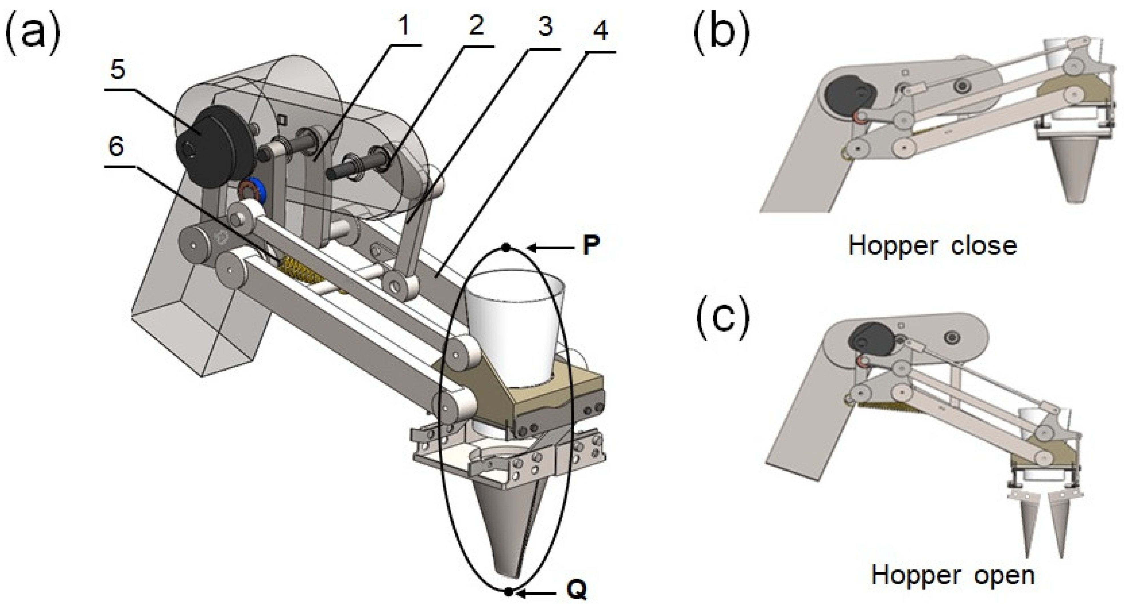
2.2. Design and Operational Mechanism of the Prototype Cabbage Transplanter

In Korea, cabbage seedlings are transplanted on ridges in single or double rows, with 600 mm row spacing and 400 mm planting distance [35]. Cylindrical biodegradable paper pots (40 × 40 mm) are more effective than plug trays for producing vigorous seedlings well-suited for transplantation [36]. After a 30-day growth period, seedlings reach optimal maturity for mechanical transplantation, requiring placement in the soil to the depth of the seedling pot [37]. Figure 2 shows a semi-automatic (seedling feeding and metering are performed manually [38]), one-row walking-type (the operator walks behind the machine, guiding through the field) cabbage transplanter currently in development. Similarly to other vegetable transplanters, a cabbage transplanter is composed of three key mechanisms: an extraction mechanism for selecting seedlings, a conveyor mechanism for transferring them, and a planting mechanism for placing the seedlings into the soil [39].
The transplanting process involves one operator manually transferring seedlings from the tray to the conveying hopper, while a second operator manages the operation of the transplanter. Seedlings are transferred sequentially from the conveying hopper to the planting hopper for transplantation. As illustrated in Figure 3, the rotary planting mechanism comprises the following components: the driving link (2), the connecting link (3), the driven link (4), the supporting link (5), and the planting hopper (6). The driving link operates as a crank-rocker mechanism, while the supporting link (1) connects the driven link to the ground. An extended lever link acts as a connection between the subsequent link and the planting hopper, integrating the cam and follower assembly that governs the opening and closing of the hopper jaws during seedling transfer and planting operations. At position P, the planting hopper receives seedlings while the cam nose remains disengaged from the follower, ensuring the hopper jaws remain closed during the transfer process. As the hopper moves to position Q, the cam nose engages with the follower, triggering the opening of the hopper jaws. This continuous operation ensures efficient transplantation. Successful transplantation relies on two critical operations: lifting the seedling and positioning it into the soil at the appropriate depth while maintaining an upright orientation. During continuous operation, power is delivered to the crank (or driving link) via a chain-sprocket system, ensuring counterclockwise rotation. This motion enables the hopper to move between positions P and Q, following a specific trajectory pathway, allowing one seedling to be transplanted with each complete rotation cycle of the transplanter.

2.3. Design Requirements

To ensure optimal seedling orientation during mechanized planting, a duck-billed planter of the transplanting mechanism positioned seedlings upright on the ridge surface at the point of deposition. During retraction from the planting hole, it was essential to maintain the planter perpendicular to the ridge. As the planter withdrew, seedlings would tilt slightly in the direction of the forward motion of the mechanism before fully detaching from the planter. To maintain seedling stability and prevent toppling, the angle between the seedlings and the ridge surface was maintained near 90°, with the angle between the planter and the ridge surface kept at a minimum of 80° [39]. The motion trajectories of the planter endpoint are illustrated in Figure 4. To ensure optimal performance of the transplanter, agronomic parameters must be maintained within specific ranges. These include a planting depth of 40–50 mm, a planting interval of 300–500 mm, and a soil moisture content of 15–25%, enabling effective operation at forward speeds of 150–350 mm/s [35]. To ensure compliance with these agronomic requirements, the absolute trajectory of the planter was required to satisfy the following conditions: (1) the vertical distance (h1) between the lowest point of the trajectory and the ridge surface should be maintained at 40–50 mm; (2) the angle (α1) between the planter and the ridge surface at the lowest trajectory point must be at least 80°; (3) the angle (α₂) between the planter and the ridge surface at the onset of withdrawal should not be less than 80°; (4) the angle (β1) between the absolute trajectory and the ridge surface during planter withdrawal must be at least 80°; and (5) the intersection distance (l) between the absolute trajectory and the ridge surface during a single cycle should be minimized [40].

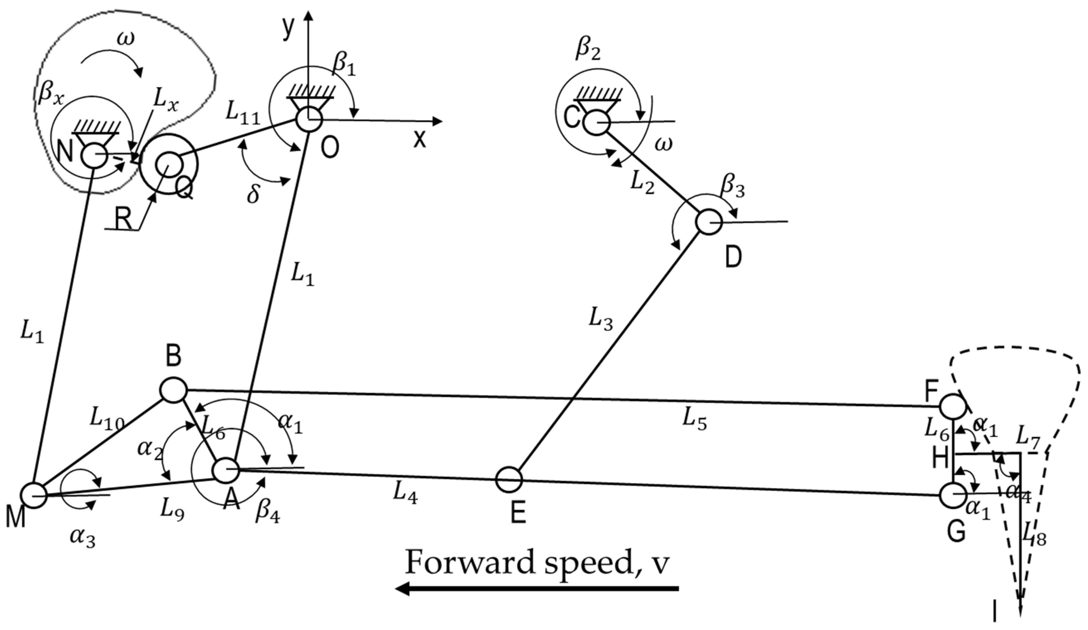
2.4. Kinematic Model of the Transplanting Mechanism

The Cartesian coordinate system for the cam–rocker-type pot seedling planting mechanism is illustrated in Figure 5. This planting mechanism consisted of a cam–rocker double-parallel four-bar system, with the cam and crank as the primary moving components. The transmission ratio between the two sprockets is 1, ensuring a constant rate relationship. The parameters and corresponding meanings of the mechanism are summarized in Table 1. Both the cam (N) and crank (CD) rotate clockwise at a constant angular velocity (ω). Through the combined action of the cam–rocker mechanism (NQOA) and the crank-connecting rod mechanism (CDE), the planting rod (HJI), which is fixed to the connecting rod (FG), is moved.
As illustrated in Figure 5, a Cartesian coordinate system is defined with point O serving as the origin. The horizontal direction is defined as the X-axis and is oriented in the positive direction corresponding to the forward movement of the mechanism. The vertical direction is designated as the Y-axis. The parameters relevant to the mathematical modeling of the mechanism are listed in Table 2.

2.4.1. Position Models

The kinematic behavior of the mechanism can be thoroughly analyzed by forming a vector loop that represents the geometric configuration. In this study, the vector loop OAEDC is used, as illustrated in Figure 5, to capture the positional relationships and interdependencies among the components of the mechanism. The mathematical formulation of this vector loop is expressed in Equation (1), enabling the calculation of position, velocity, and acceleration as follows [40,41,42]:
L OA + L AE = L OC + L CD + L DE
Displacement of points A, D, and E, are expressed as Equations (2)–(7) as follows:
X A = L 1 cos β 1
  Y A   = L 1 sin β 1
X D = L 2 cos β 2 + X C
Y D = L 2 sin β 2 + Y C
X E = X A + L 4 cos β 4 = X D + L 3 cos β 3
Y E = Y A + L 4 sin β 4 = Y D + L 3 sin β 3
By solving Equations (6) and (7), Equations (8)–(10) can be obtained as follows:
X A X D + L 4 cos β 4 = L 3 cos β 3
( Y A Y D ) + L 4 sin β 4 = L 3 sin β 3
acos β 3 + bsin β 4 c = 0
where a = 2 X D X A L 4 , b = 2 Y D Y A L 4 , and c = L 4 2 L 3 2 + X D X A 2 + Y D Y A 2 .
This yields β 4 = 2 arctan = b a 2 + b 2 c 2 a + c
Displacement of points G, H, and I is expressed as Equations (11)–(16) as follows:
X G = X A + L 5 cos β 4
Y G   = Y A + L 5 sin β 4
X H = X G + μ L 6 cos α 1
Y H   = Y G + μ L 6 sin α 1
X I = X A + L 5 cos β 4 + μ L 6 cos α 1 + L 7 vt
Y I   = Y A + L 5 sin β 4 + μ L 6 sin α 1 L 8
where v represents the forward speed of the mechanism, and μ denotes the ratio of the length of connecting rods GH and GF.

2.4.2. Velocity and Acceleration Models

The displacement equations with respect to time provide velocity and, by taking derivatives, yield acceleration. The velocity and acceleration of point I are represented in Equations (17)–(20) as follows:
X ˙ I = X ˙ A L 5 β ˙ 4 sin β 4   v
Y ˙ I = Y ˙ A L 5 β ˙ 4 cos β 4
X ¨ I = X ¨ A L 5 β ¨ 4 sin β 4 β ˙ 4 2 L 5 cos β 4
Y ¨ I = Y ¨ A L 5 β ¨ 4 cos β 4 β ˙ 4 2 L 5 sin β 4
The magnitudes of velocity and acceleration for the planting hopper are detailed in Equation (21) and Equation (22), respectively, as follows:
v m = v x 2 + v y 2
a m = a x 2 + a y 2
The power requirement (P) for operating the planting mechanism is determined as a function of velocity (vₘ), acceleration (aₘ), and mass (m). The mathematical expression for calculating the power needed by the mechanism is presented in Equation (23) as follows:
P = ma m v m
To analyze the motion trajectory characteristics of the planting hopper, five trial combinations were simulated with varying lengths for the main links. The crank length ranged from 45 to 65 mm, increasing by 5 mm increments with each step. Likewise, the lengths of the coupler, follower, end effector, and fixed bar were adjusted in increments to explore the influence on motion trajectory. Specifically, the coupler length varied from 130 to 170 mm, increasing by 10 mm per step; the follower length ranged from 115 to 135 mm, increasing by 5 mm per step. The end-effector length spanned from 210 to 250 mm, increasing by 10 mm per step; the fixed bar length varied from 110 to 150 mm, also increasing by 10 mm per step. The variations in length were used in Equations (15) and (16) to compute and visualize the motion trajectory corresponding to each trial combination. Table 3 provides a comprehensive summary of the parameters associated with each main arm length configuration evaluated during the planting hopper simulations.

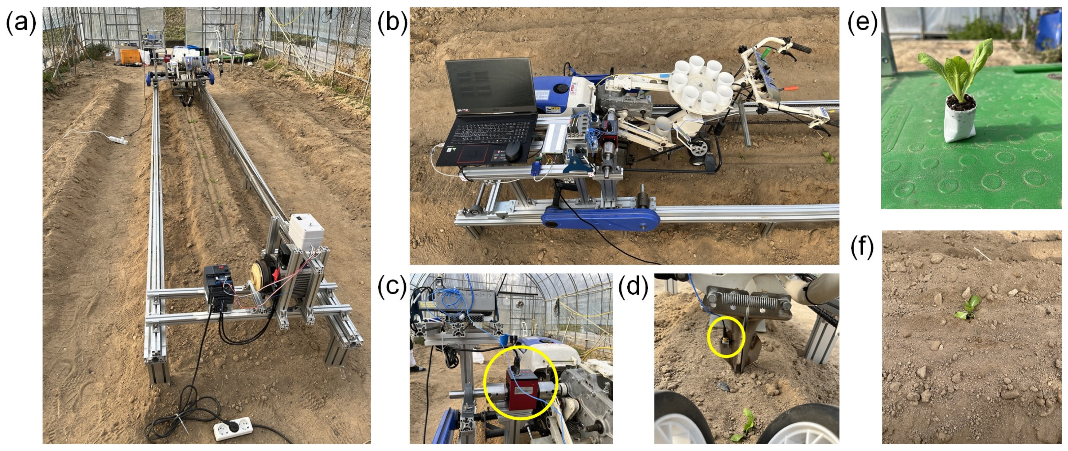
2.4.3. Simulation and Validation Procedures of the Planting Mechanism

The planting mechanism serves as a major component of the device, where an optimized design is fundamental for ensuring effective seedling transplantation. A three-dimensional (3D) model was developed of the rotary planting mechanism, and the operational dynamics were animated and analyzed using commercial simulation software (SOLID WORKS 2018, Dassault Systems SolidWorks Corp., Waltham, MA, USA). The parameters considered for simulating the rotary planting mechanism are provided in Table 4.
To verify the computational findings, a physical prototype of the dibbling mechanism was developed, and transplantation experiments were carried out using a test bench constructed from a 40 mm × 80 mm aluminum profile frame, as shown in Figure 6a. The test bench was driven by a three-phase electric motor (model: EON10248, Xinming Electronics Co., Ltd., Yantai, China) coupled with a chain-sprocket system to attain the required operational speeds [33]. A 1.54 kW gasoline engine powered the dibbling mechanism, with motor speeds controlled through individual inverters as shown in Figure 6b. A torque sensor (model: DYN-200, Shanghai Qiyi Co., Ltd., Shanghai, China) was integrated into the power transmission line between the motor and the dibbling mechanism, as illustrated in Figure 6c, to monitor power consumption during operation, with sensor data collected using a data acquisition device. To assess acceleration, a tri-axial acceleration sensor (model: 356A15, PCB Piezotronics, Inc., Depew, NY, USA) (Figure 6d) was attached to the dibbling hopper, with acceleration signals recorded using a four-channel data logger (model: NI cDAQ-9178, National Instruments, Austin, TX, USA) and a four-channel module (model: NI 9234, National Instruments, Austin, TX, USA). Torque and acceleration data were subsequently acquired using a python based program for each sensor, respectively and analyzed the data using a commercial software (MATLAB R2020b; The MathWorks, Natick, MA, USA). Figure 6e illustrates the cabbage seedling with the biodegradable (paper) pot used during the test, while Figure 6f shows the seedling after transplantation into the soil.
Torque data obtained from the sensor were processed using a 20-point symmetric moving average technique to ensure smoothness and accuracy [43]. Fast Fourier transform (FFT) and inverse fast Fourier transform (IFFT) techniques were applied to minimize noise in the acceleration signals obtained from the acceleration sensors. The velocity of dibbling hopper was subsequently determined from the refined acceleration data over time. Furthermore, an open-source, video-based tracking software was used to analyze the working trajectory of the dibbling mechanism. A smartphone recorded slow-motion video at 1080-pixel resolution and 30 frames per second (FPS) for this analysis. The dibbling mechanism was initially tested at a speed of 60 rpm without soil contact to measure power consumption and acceleration, with results compared to simulation outputs. Thirty-day-old cabbage seedlings were transplanted into ridges using the dibbling mechanism, which operated at a rotational speed of 60 rpm and a forward speed of 300 mm/s. During the process, power consumption was measured and recorded. Transplantation trials were conducted five times on a test bed measuring 6000 mm × 350 mm × 200 mm. The experiments were performed in a plastic greenhouse at Agricultural Research Area, Chungnam National University, Daejeon, Republic of Korea, on a soil bed, classified as sandy loam [28]. To provide a comprehensive characterization of the test site, key soil properties were evaluated, including moisture content, temperature, electrical conductivity (EC), texture, bulk density, and cone index (CI). These parameters were assessed due to their significant influence on soil–machine interaction dynamics. The CI was measured to a depth of 150 mm using a handheld penetrometer (model: DIK-5590, Daiki Rika Kogyo Co., Ltd., Saitama, Japan), while soil moisture, temperature, and electrical conductivity (EC) were measured using a soil water content sensor (model: WT1000B, Mirae Sensor, Seoul, Republic of Korea). The bulk density of the soil was determined through the oven-dry method.

3. Results

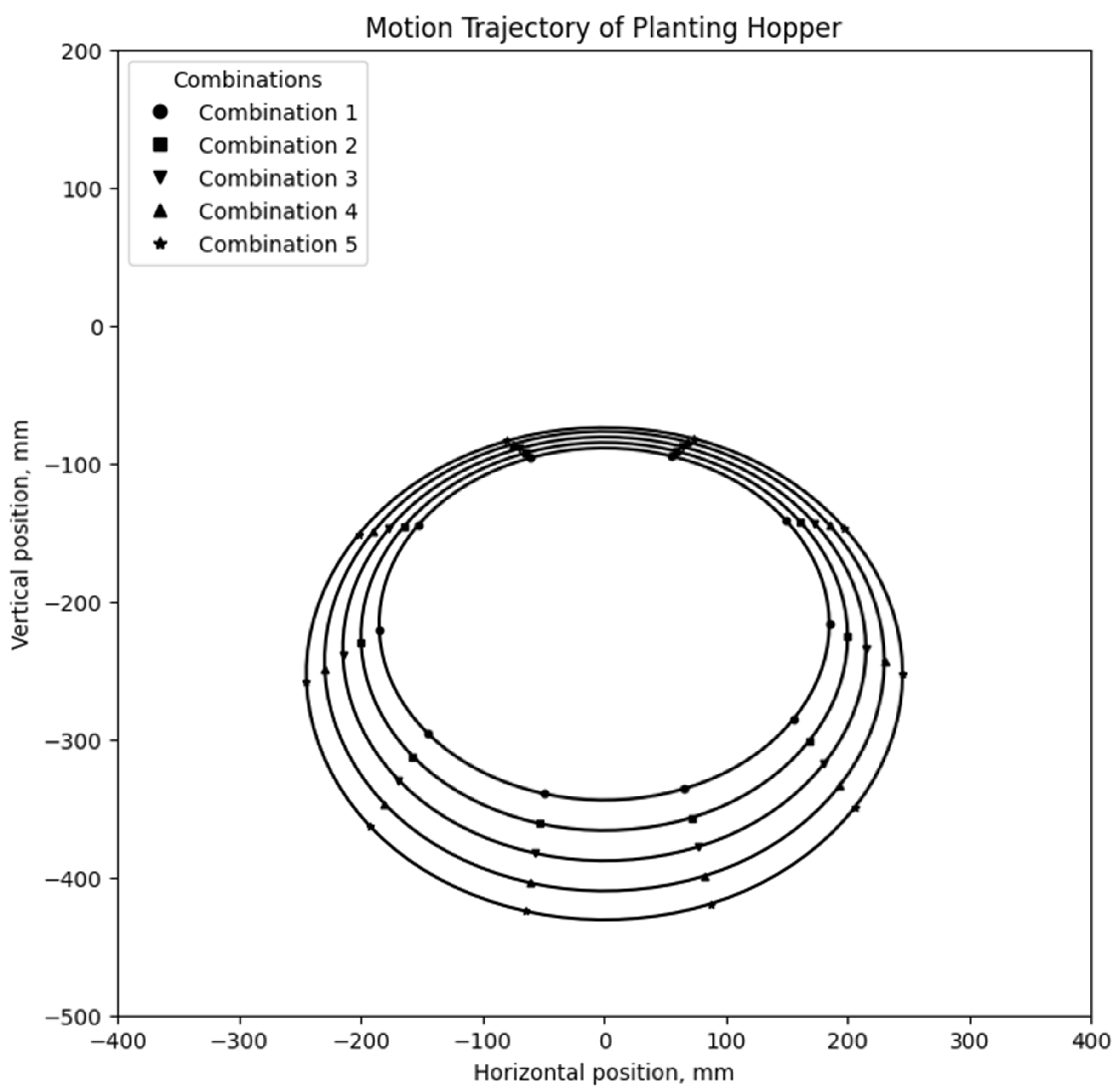
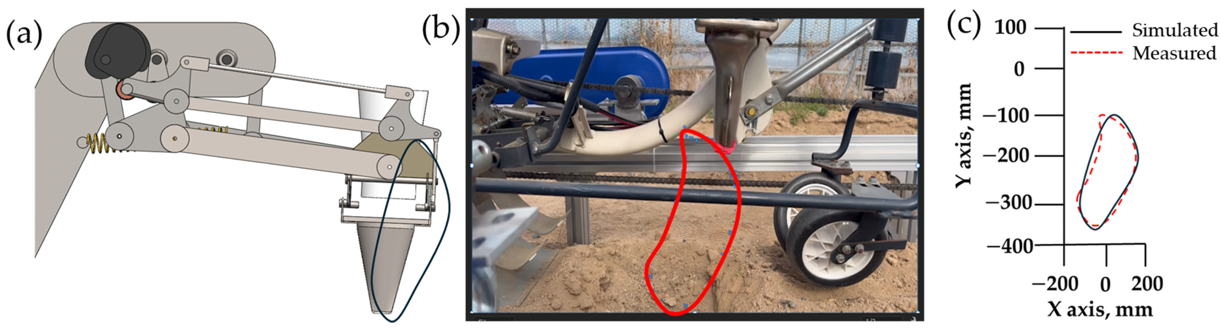
3.1. Motion Path Analysis of the Dibbling Hopper

Five trial parameter combinations were formulated in accordance with the defined design criteria for the trajectory and operational posture of the cam-follower transplanting mechanism. The driving link length was varied from 45 mm to 65 mm, the connecting arm from 130 mm to 170 mm, the guide bar from 115 mm to 135 mm, and the end-effector link from 210 mm to 250 mm. The dibbling hopper length was consistently maintained at 153 mm across all configurations, as this dimension was found optimal for transplanting pot seedlings [33]. Each parameter combination produced the intended oval-shaped trajectory over time, as presented in Figure 7. Horizontally, the dibbling hopper exhibited motion within a range of ±385 mm to ±445 mm across all five configurations. Vertically, the planting hopper displayed upward and downward movement within the following ranges for each trial: −89 to −344 mm; −85 to −366 mm; −81 to −388 mm; −77 to −410 mm; and −74 to −431 mm.
The elliptical motion path was derived from the trajectories generated at various rotational speeds, with the results validated through simulation. During cabbage planting operations, the trajectory at 60 rpm demonstrated greater stability compared to other speeds, exhibiting minimal vibration. Consequently, 60 rpm was determined to be the optimal rotational speed for this planting mechanism. Figure 8 presents a comparison of the motion path trajectory for the cam-follower transplanting mechanism, highlighting the alignment between simulated data and experimental validation.

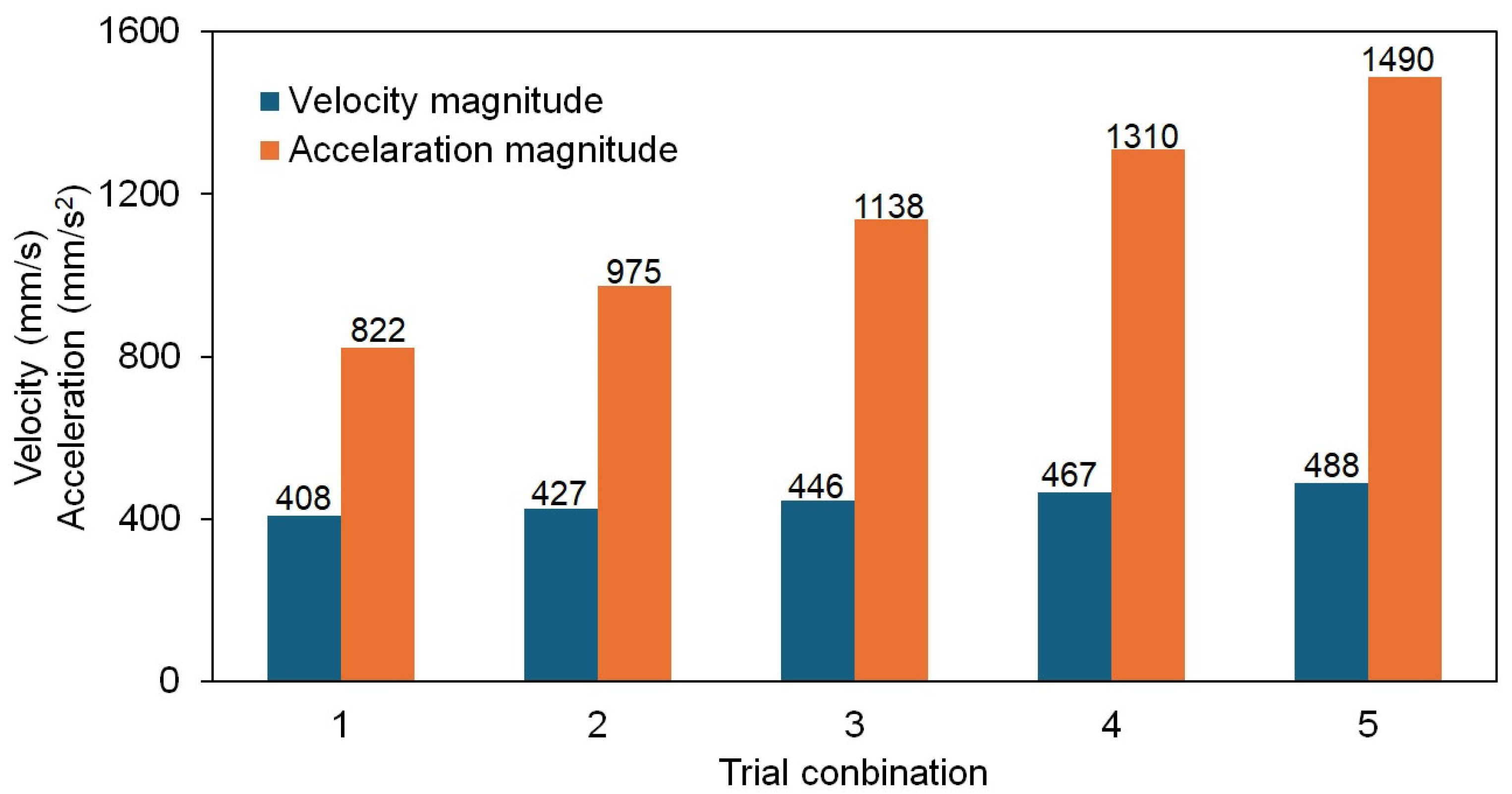
3.2. Analysis of Dibbling Hopper Velocity and Acceleration

At a rotational speed of 60 rpm, increases in velocity, acceleration, and power consumption were observed for the dibbling mechanism, as shown in Figure 9, with variations in the lengths of the crank, coupler, and connecting arms. However, increasing the dimensions of these components necessitated the use of additional material, resulting in a higher overall mass for the mechanism. Given the interdependence of velocity, acceleration, and mass with power consumption, these changes directly contributed to elevated energy requirements [33]. The analysis across the tested parameter combinations revealed maximum velocity, acceleration, and power consumption ranges of 408–488 mm/s, 822–1490 mm/s2, and 5–50 W, respectively. To enhance cost-efficiency and minimize energy usage, reducing the dimensions of the crank, coupler, and connecting arms is recommended, provided that the adjustments satisfy the design requirements and maintain operational effectiveness.
To optimize the design and motion trajectory of the transplanting mechanism, arm lengths were identified as critical variables due to their substantial impact on planting trajectory. Figure 10 presents the evaluated planting trajectories corresponding to various arm length configurations. Point D indicates the intersection of the planting and return paths within the dibbling hopper trajectory, while points E and F represent the trajectory intersections with the ground, marking the planting and return paths, respectively. Each trajectory illustrates a unique set of parameter combinations. Although points E and F do not align vertically across all configurations, only in combination 2, points E and F are almost directly over point D, resulting in the smallest planting hole among all the design parameters. Additionally, combination 2 minimized transplant damage on mulched beds. In combination 1, seedlings tended to be dragged forward, while in combinations 3 to 5, they lagged behind. Consequently, only combination 2 achieved upright seedling orientation during planting, which is essential for optimal growth and yield for the cabbage.
The velocities obtained from both simulations and experimental measurements were evaluated for the mechanism operating at a rotational speed of 60 rpm, corresponding to a planting cycle duration of one second. For velocity validation of the proposed planting mechanism, a crank length of 50 mm and a follower length of 120 mm were selected, as specified in trial 2 (Table 3). Table 5 compares the simulated and experimental velocities and accelerations for the X- and Y-components. No velocity was observed in the Z-axis during simulation. The duration for conducting acceleration measurements, both experimentally and through simulation, matched the duration used for velocity analysis. Figure 11 illustrates the maximum acceleration values obtained from both simulations and experimental tests in the X- and Y-axes. The maximum simulated accelerations were ±972.45 mm/s2 along the X-axis and ±6847.57 mm/s2 along the Y-axis. Comparatively, the maximum experimental accelerations ranged from +990.56 mm/s2 to −1241.46 mm/s2 in the X-direction and from +8751.27 mm/s2 to −8664.38 mm/s2 in the Y-direction.
The experimental findings indicated that the maximum velocity and acceleration values exceeded those predicted by simulations. This difference likely derived from the real-time conditions of the experimental setup, where factors such as vibration, speed fluctuations, and external disturbances (e.g., minor operational errors) introduced variability. As illustrated in Figure 11, the actual motion trajectories deviated slightly from the elliptical patterns observed in the simulations. Despite these variations, the measured levels of vibration and acceleration were within acceptable tolerances for the design specifications of the planting mechanism. Further research is recommended to evaluate the impact of vibration, speed fluctuations, and external forces on the overall performance of the mechanism.
Numerous studies have reported similar findings in motion analysis for transplanting mechanisms. For instance, research on a pepper transplanter mechanism [40] observed velocity and acceleration ranges of 400 to 1100 mm/s and 500 to 2200 mm/s in the X- and Y-directions, with acceleration values ranging from 1330 to 23,740 mm/s2 and 2420 to 6140 mm/s2, respectively. Similarly, a study on a tomato seedling picking device (Han et al., 2015) [14] identified maximum velocities and accelerations of 1200 to 2100 mm/s and 103,800 to 86,900 mm/s2 along the X- and Y-axes, respectively. In comparison, this study achieved an optimal velocity range with lower acceleration values than those reported in previous studies. A slightly reduced velocity can contribute to improved seedling transfer rates [14], while excessive velocities and accelerations may risk damaging seedlings due to the rapid transfer of energy and force during operation [43]. Additionally, high peak velocities and accelerations increase the likelihood of missing or dropping seedlings [44]. Therefore, monitoring and controlling velocity and acceleration are essential in developing a planting prototype that meets performance and design requirements.

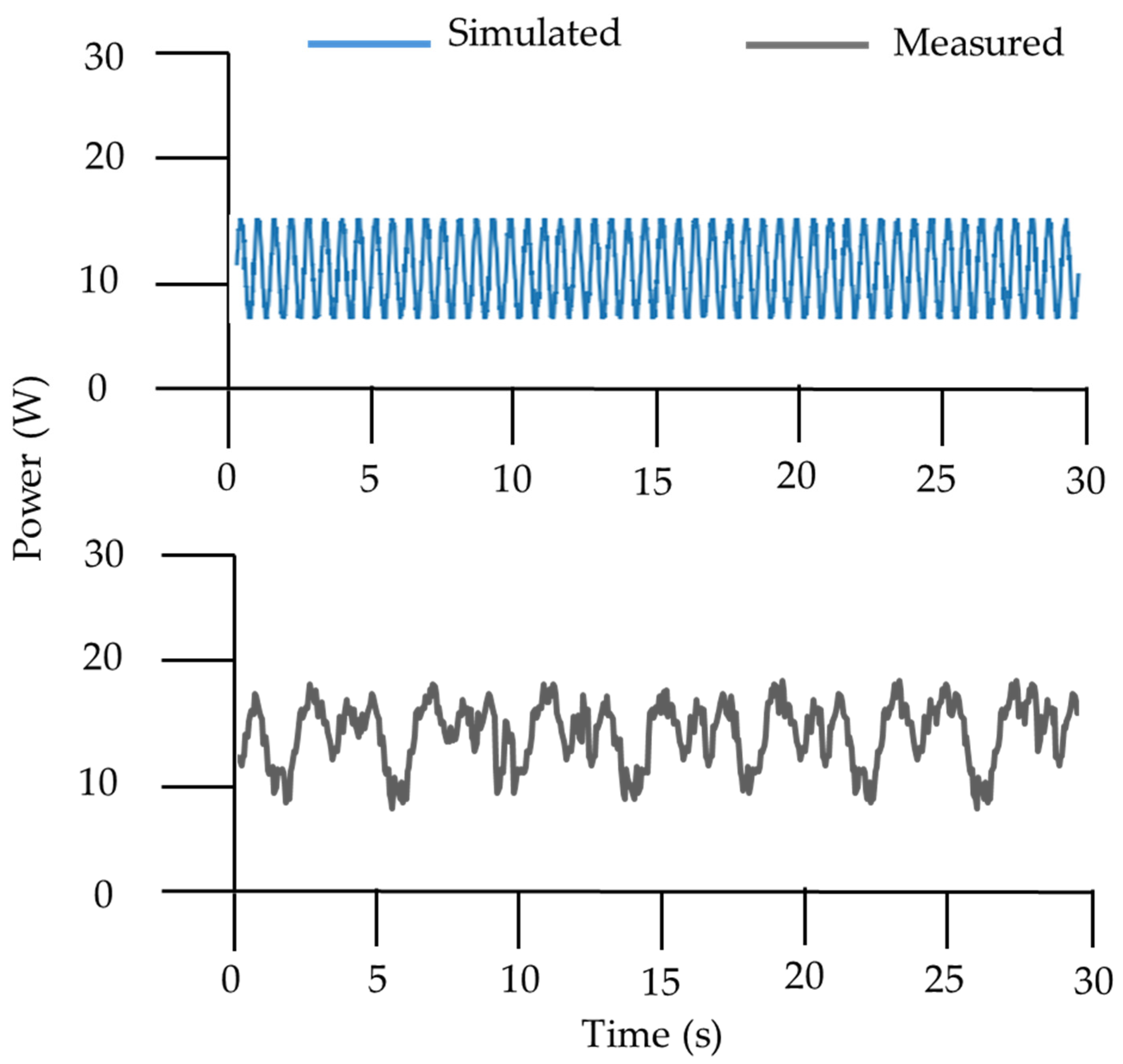
3.3. Power Requirements for Transplanting Mechanism

The power consumption of the planting mechanism was evaluated for both the simulated model and the physical prototype, with tests performed at a rotational speed of 60 rpm to determine power requirements. Figure 12 displays the results of simulated and experimental power consumption. The maximum power requirements for the planting mechanism were 15.8 W in the simulation and 17.4 W in the experimental measurement, both values measured in the absence of soil contact. The experimental power consumption was approximately 10.13% higher than the simulated value. This variation in power demand is likely due to the gear-driven nature of the mechanism, where the transmission efficiency typically falls within a range of 94% to 99.5% [33]. Additionally, factors such as frictional resistance in the rotating shaft and vibrations generated by the test bench may have contributed to reduced power transfer efficiency, resulting in the observed discrepancy. The power demand also exhibited variability and noise, with sudden fluctuations (Figure 12) potentially causing strain on mechanical components and reducing the operational lifespan of the machine. This emphasizes the importance of monitoring vibration levels during both the design phase and field testing of the prototype. Any sudden or significant increase in vibration may indicate increased forces, loss of structural integrity, or gear wear [45]. Minimizing power fluctuations is crucial prior to commercialization and large-scale production of the planting mechanism.

4. Discussion

The study tested a bar-type planting mechanism for a biodegradable pot cabbage transplanter, focusing on kinematic analysis to optimize path trajectory, enhance working speed, and improve transplanting success rates. The optimized mechanism, constructed and validated using a test bench system, demonstrated close alignment between theoretical calculations and actual measurements, confirming the accuracy of the design. The optimal lengths for the driving link, connecting arm, guide bar, and end-effector link were found to be 50, 140, 120, and 220 mm, respectively, with the planting hopper length held constant at 150 mm throughout the kinematic analysis. The maximum required power for the planting mechanism during validation tests was 17.4 W. Tests on the transplanting system confirmed that the mechanism achieved the desired planting depth and spacing, with seedling uprightness and soil disturbance remaining within agronomic requirements.
Studying the working trajectory of transplanting mechanisms is essential for achieving accuracy, stability, and efficiency in agricultural mechanical planting applications. This study evaluated a cam-follower transplanting mechanism, focusing on optimizing the trajectory and working posture to enhance planting performance. By developing and testing five parameter combinations and analyzing the elliptical motion path with varying main arm link lengths, 60 rpm was identified as the optimal speed for maintaining consistent trajectory alignment. The findings of this study align with those of Reza et al. [46], where 60 rpm was identified as the optimal speed for onion transplanting, with power consumption of 35.4 W and transplanting rates of 60 and 120 seedlings/min for single and double rows, respectively. Unlike the gear-driven dibbling mechanism used by the study, this study employed a cam-follower double-parallel hopper-type transplanter, offering smoother seedling delivery, precise positioning, and reduced mechanical stress. The advanced design enhances efficiency and reliability, particularly under varied field conditions, highlighting the evolution of transplanting technologies to meet diverse agricultural needs.
These findings also align with Zhu et al. [47], who demonstrated the utility of high-speed photography in improving trajectory accuracy for seedling pick-up mechanisms, achieving a success rate of 94.2% and an efficiency of 60 plants per minute per row. In a related study, Xu et al. [40] developed a geared five-bar transplanting mechanism for Salvia miltiorrhiza and validated its trajectory using high-speed photography, showing close alignment between the actual and theoretical trajectories. This method demonstrates the effectiveness of kinematic modeling and orthogonal experimental design in optimizing trajectory parameters. Consistent with these findings, the results of this study emphasize the importance of trajectory stability and minimal vibration in transplanting applications, confirming that the cam-follower mechanism operating at 60 rpm provides stable and accurate seedling placement. Further studies on rotary planting mechanisms with various link lengths and three-gear configurations identified an oval motion path, with vertical movement covering twice the horizontal distance.
Additionally, different commercial simulation software verified that a “boat-bottom” trajectory enhanced planting efficiency and stability for sweet potato transplanters [48]. For challenging terrain, Shao et al. [48] designed a planetary five-bar mechanism that produced a “spindle” trajectory, minimizing planting cavity diameter and enhancing seedling uprightness. This study analyzed the velocity and acceleration of a dibbling mechanism operating at a rotational speed of 60 rpm to assess how variations in crank, coupler, and connecting arm lengths influence performance. Results indicated that increasing the lengths of these components led to higher velocity, acceleration, and power consumption, with maximum ranges recorded at 408–488 mm/s and 822–1490 mm/s2, respectively. Experimental measurements showed peak values exceeding those in simulations, likely due to real-world factors such as vibration, speed variability, and external disturbances that introduced minor discrepancies in measurements [47]. These findings suggest that, although larger components can enhance movement speed, they may also increase energy demands and structural mass, impacting overall efficiency. Similar studies support these observations. For instance, Iqbal et al. [32] reported minor deviations between measured and calculated velocities along the X- and Y-axes due to motor friction and other practical influences. Additionally, Jiaodi et al. [49] observed that acceleration in the x-direction increased as velocity decreased, thereby optimizing planting efficiency. These insights indicate that carefully adjusting component dimensions can improve stability and reduce power consumption, supporting more cost-effective and reliable transplanting operations in applied agricultural settings.
Power consumption is an essential factor in evaluating the operational efficiency of planting mechanisms. In this study, both a simulated model and a physical prototype of the planting mechanism were analyzed at a rotational speed of 60 rpm to assess power requirements. The maximum power consumption for the simulated model was recorded at 15.8 W, while the physical prototype required 17.4 W, with approximately 10.54% higher than the simulated estimates. This differences can be attributed to the gear-driven design, where transmission efficiency ranged between 94% and 99.5%. However, factors such as frictional losses from the rotating shaft and vibrations from the test bench contributed to a reduction in actual power transfer efficiency, resulting in lower-than-expected values [50]. Supporting studies corroborate these findings. For example, Iqbal et al. [32] reported an 11.04% increase in measured power consumption over simulated values, also attributed to frictional and vibrational losses. Additionally, Rahul et al. [51] investigated the power requirements of a robotic arm used for handling paper pot seedlings, noting that power consumption was affected by the number of joints, link weight, and payload (such as pot seedlings). Under a constant 12 V DC supply, the robotic arm consumed a maximum current of 1.33 A, corresponding to a power requirement of 16 W. These results showed the importance of accounting for real-world inefficiencies in power consumption analysis.
Future research trends in transplanting mechanisms are likely to focus on enhancing energy efficiency, precision, and adaptability to diverse crop types and terrains. With advancements in kinematic modeling, simulation accuracy, and material science, future designs may incorporate lightweight, durable materials to reduce power consumption and improve durability in challenging environments. Additionally, integrating smart sensors and machine learning algorithms can optimize component adjustments in real time, adapting the mechanism’s speed and motion path based on crop type, soil conditions, and terrain. Exploring alternative power sources, such as renewable energy systems, may also contribute to more sustainable agricultural practices by reducing dependency on conventional power sources. Finally, further examination of multi-functional mechanisms capable of handling various planting tasks could streamline agricultural processes, enhancing overall productivity and efficiency.

5. Conclusions

In this study, a bar-type planting mechanism was developed for a biodegradable pot cabbage transplanter. Kinematic analysis was conducted to determine suitable link combinations and assess the ability of the mechanism to optimize path trajectory, enhancing working speed and transplanting success rate. Based on the optimal parameter combination, a test bench system for the transplanting mechanism was constructed. Using mechanical design software, the actual trajectory of the prototype was analyzed. The test bench results showed close alignment between the actual measurements and theoretical calculations, confirming the accuracy of the optimization of the mechanism.
Key parameters, including optimal link dimensions and power requirements (17.4 W), were identified, ensuring precise planting depth and spacing while maintaining agronomic standards for seedling uprightness and minimal soil disturbance. The cam-follower transplanting mechanism operating at 60 rpm was identified as a reliable solution for achieving trajectory stability and consistent seedling placement, offering advantages such as reduced mechanical stress and enhanced efficiency over conventional gear-driven systems. Findings from related studies reinforced the importance of trajectory accuracy, power efficiency, and stability in improving agricultural planting performance. Further investigation is recommended to analyze the dynamic behavior of the planting mechanism. The findings from this study may support the adoption of mechanized transplanting processes for biodegradable pot seedlings.

Author Contributions

Conceptualization, M.R.A. and S.-O.C.; methodology, M.R.A., M.N.R. and S.-O.C.; software, M.R.A.; validation, M.R.A., M.N.R., S., E.H., M.A.H. and B.-S.K.; formal analysis, M.R.A., M.N.R., S., E.H. and M.A.H.; investigation, B.-S.K. and S.-O.C.; resources, S.-O.C.; data curation, M.R.A., M.N.R., S., E.H., M.A.H. and B.-S.K.; writing—original draft preparation, M.R.A.; writing—review and editing, M.N.R., E.H., B.-S.K. and S.-O.C.; visualization, M.R.A., M.N.R., S., E.H. and M.A.H.; supervision, S.-O.C.; project administration, S.-O.C.; funding acquisition, S.-O.C. All authors have read and agreed to the published version of the manuscript.

Funding

This work was supported by Korea Institute of Planning and Evaluation for Technology in Food, Agriculture and Forestry (IPET), through Machinery Mechanization Technology Development Program for Field Farming, funded by Ministry of Agriculture, Food and Rural Affairs (MAFRA) (Project No. RS-2023-00236991), Republic of Korea.

Data Availability Statement

The data are contained within the article.

Conflicts of Interest

Author Beom-Sun Kang was employed by the company HSM Co., Ltd. The remaining authors declare that the research was conducted in the absence of any commercial or financial relationships that could be construed as a potential conflict of interest.

References

  1. Jang, D.J.; Chung, K.R.; Yang, H.J.; Kim, K.S.; Kwon, D.Y. Discussion on the origin of kimchi, representative of Korean unique fermented vegetables. J. Ethn. Foods 2015, 2, 126–136. [Google Scholar] [CrossRef]
  2. KOSTAT. Production of Autumn Cabbages, Autumn Radishes, Beans, Apples and Pears in 2023. Available online: https://sri.kostat.go.kr/board.es?mid=a20102010000&bid=11712&tag=&act=view&list_no=429198&ref_bid= (accessed on 26 September 2024).
  3. Habineza, E.; Ali, M.; Reza, M.N.; Woo, J.K.; Chung, S.O.; Hou, Y. Vegetable transplanters and kinematic analysis of major mechanisms: A review. Korean J. Agric. Sci. 2023, 50, 113–129. [Google Scholar] [CrossRef]
  4. Ali, M.R.; Ali, M.; Reza, M.N.; Jang, G.H.; Kang, B.S.; Choi, I.J.; Koo, J.M. Trends of vegetable transplanting mechanism for biodegradable seedling pots: A review. Precis. Agric. Sci. Technol. 2024, 6, 179–194. [Google Scholar]
  5. Khadatkar, S.M.; Mathur, M.; Gaikwad, B.B. Automation in transplanting: A smart way of vegetable cultivation. Curr. Sci. 2018, 115, 1884–1892. [Google Scholar] [CrossRef]
  6. Brodhagen, M.; Goldberger, J.R.; Hayes, D.G.; Inglis, D.A.; Marsh, T.L.; Miles, C. Policy considerations for limiting unin-tended residual plastic in agricultural soils. Environ. Sci. Pol. 2017, 69, 81–84. [Google Scholar] [CrossRef]
  7. Zumstein, M.T.; Schintlmeister, A.; Nelson, T.F.; Baumgartner, R.; Woebken, D.; Wagner, M.; Kohler, H.P.E.; McNeill, K.; Sander, M. Biodegradation of synthetic polymers in soils: Tracking carbon into CO2 and microbial biomass. Sci. Adv. 2018, 4, eaas9024. [Google Scholar] [CrossRef] [PubMed]
  8. Liu, E.K.; He, W.Q.; Yan, C.R. ‘White revolution’ to ‘white pollution’—Agricultural plastic film mulch in China. Environ. Res. Lett. 2014, 9, 091001. [Google Scholar] [CrossRef]
  9. Gaylor, M.O.; Harvey, E.; Hale, R.C. Polybrominated diphenyl ether (PBDE) accumulation by earthworms (Eisenia fetida) exposed to biosolids-, polyurethane foam microparticle-, and penta-BDE-amended soils. Environ. Sci. Technol. 2013, 47, 13831–13839. [Google Scholar] [CrossRef]
  10. Huerta Lwanga, E.; Gertsen, H.; Gooren, H.; Peters, P.; Salanki, T.; van der Ploeg, M.; Besseling, E.; Koelmans, A.A.; Geissen, V. Incorporation of microplastics from litter into burrows of Lumbricus terrestris. Environ. Pollut. 2017, 220, 523–531. [Google Scholar] [CrossRef] [PubMed]
  11. Meng, Y.; Guo, Z.; Yao, H.; Yeung, K.W.; Thiyagarajan, V. Calcium carbonate unit realignment under acidification: A potential compensatory mechanism in an edible estuarine oyster. Mar. Pollut. Bull. 2019, 139, 141–149. [Google Scholar] [CrossRef] [PubMed]
  12. Tomadoni, B.; Merino, D.; Alvarez, V.A. Biodegradable materials for planting pots. In Advanced Applications of Bio-Degradable Green Composites; Materials Research Forum LLC: Millersville PA, USA, 2020; Volume 68, p. 85. [Google Scholar]
  13. Juanga-Labayen, J.P.; Labayen, I.V.; Yuan, Q. A review on textile recycling practices and challenges. Textiles 2022, 2, 174–188. [Google Scholar] [CrossRef]
  14. Han, L.; Mao, H.; Kumi, F.; Hu, J. Development of a Multi-Task Robotic Transplanting Workcell for Greenhouse Seedlings. Appl. Eng. Agric. 2018, 34, 335–342. [Google Scholar] [CrossRef]
  15. Prasanna Kumar, G.V.; Raheman, H. Volume of vermicompost-based potting mix for vegetable transplants determined using fuzzy biomass growth index. Int. J. Veg. Sci. 2010, 16, 335–350. [Google Scholar] [CrossRef]
  16. Nandede, B.M.; Raheman, H.; Kumar, G.P. Standardization of potting mix and pot volume for the production of vegetable seedlings in paper pot. J. Plant Nutr. 2014, 37, 1214–1226. [Google Scholar] [CrossRef]
  17. Jang, Y.N.; An, S.W.; Chun, H.; Lee, H.J.; Wi, S.H. The growth of cucumber seedlings grown in paper pot trays affected by nutrient management during seedling period, seedling age, and night temperature after transplanting. J. Bio-Environ. Control. 2019, 28, 396–403. [Google Scholar] [CrossRef]
  18. Park, J.H.; Lee, G.H.; Lee, H.M.; Madhavi, B.G.K.; Arulmozhi, E.; Bhujel, A.; Moon, B.E.; Kim, H.T. Physical properties and plant growth according to the content of additives in the biodegradable pot for mechanical transplanter. JALS 2022, 56, 129–134. [Google Scholar] [CrossRef]
  19. Wang, X.D.; Feng, J. State and development of transplanting mechanization with mulch film at home and abroad. Chin. Agric. Mech. 2005, 3, 25–28. [Google Scholar]
  20. Prasanna Kumar, G.V.; Raheman, H. Vegetable transplanters for use in developing countries—A review. Int. J. Veg. Sci. 2008, 14, 232–255. [Google Scholar] [CrossRef]
  21. Yu, X.T.; Hu, L.L.; Hu, Z.C. Development trend and general situation of nonirrigated farmland transplanting mechanization in China. J. Anhui Agric. Sci. 2012, 40, 614–616. [Google Scholar]
  22. Nambu, T.; Tanimura, M. Development of automatic transplanter using chain pot for vegetable crops. Int. Symp. Transpl. Prod. Syst. 1992, 319, 541–546. [Google Scholar] [CrossRef]
  23. Suggs, C.W.; Thomas, T.N.; Eddington, D.L.; Peel, H.B.; Seaboch, T.R.; Gore, J.W. Self-feeding transplanter for tobacco and vegetable crops. Appl. Eng. Agric. 1987, 3, 148–152. [Google Scholar] [CrossRef]
  24. Kumar, G.V.P.; Raheman, H. Development of a walk-behind type hand tractor-powered vegetable transplanter for paper pot seedlings. Biosyst. Eng. 2011, 110, 189–197. [Google Scholar] [CrossRef]
  25. Lee, M.H.; Moon, B.E.; Jo, J.M.; Choi, T.H.; Kim, H.T. Development of automatic type transplanter for biodegradable seed-ling pot. Proc. Conf. Korean Soc. Agric. 2017, 22, 136. [Google Scholar]
  26. Paudel, B.; Basak, J.K.; Jeon, S.W.; Deb, N.C.; Karki, S.; Kim, H.T. Development and field testing of biodegradable seedling plug-tray cutting mechanism for automated vegetable transplanter. J. Agric. Eng. 2024, 55. [Google Scholar] [CrossRef]
  27. Jin, X.; Li, D.Y.; Ma, H.; Ji, J.T.; Zhao, K.X.; Pang, J. Development of single row automatic transplanting device for potted vegetable seedlings. Int. J. Agric. Biol. Eng. 2018, 11, 67–75. [Google Scholar] [CrossRef]
  28. Paradkar, V.; Raheman, H.; Rahul, K. Development of a metering mechanism with serial robotic arm for handling paper pot seedlings in a vegetable transplanter. Artif. Intell. Agric. 2021, 5, 52–63. [Google Scholar] [CrossRef]
  29. Chen, B.; Hu, G.; Sun, S.; Xiao, M.; Sun, C. Design and experimental study of intermittent automatic grouping dropping plug seedling mechanism of fixed seedling cups. Appl. Sci. 2022, 12, 11125. [Google Scholar] [CrossRef]
  30. Du, X.; Yun, Z.; Jin, X.; Li, P.; Gao, K. Design and experiment of automatic adjustable transplanting end-effector based on double-Cam. Agriculture 2023, 13, 987. [Google Scholar] [CrossRef]
  31. Dihingia, P.C.; Prasanna Kumar, G.V.; Sarma, P.K. Development of a hopper-type planting device for a walk-behind hand-tractor-powered vegetable transplanter. J. Biosyst. Eng. 2016, 41, 21–33. [Google Scholar] [CrossRef]
  32. Iqbal, M.Z.; Islam, M.N.; Chowdhury, M.; Islam, S.; Park, T.; Kim, Y.J.; Chung, S.O. Working speed analysis of the gear-driven dibbling mechanism of a 2.6 kW walking-type automatic pepper transplanter. Machines 2021, 9, 6. [Google Scholar] [CrossRef]
  33. Markumningsih, S.; Hwang, S.J.; Kim, J.H.; Jang, M.K.; Shin, C.S.; Nam, J.S. Comparison of consumed power and safety of two types of semi-automatic vegetable transplanter: Cam and four-bar link. Agriculture 2023, 13, 588. [Google Scholar] [CrossRef]
  34. Choi, W.C.; Kim, D.C.; Ryu, I.H.; Kim, K.U. Development of a seedling pick-up device for vegetable transplanters. Trans. Am. Soc. Agric. Biol. Eng. 2002, 45, 13–19. [Google Scholar]
  35. Kim, S.; Rho, H.Y.; Kim, S. The effects of climate change on heading type Chinese cabbage (Brassica rapa L. ssp. pekinensis) economic production in South Korea. Agronomy 2022, 12, 3172. [Google Scholar] [CrossRef]
  36. Seo, T.C.; An, S.W.; Kim, S.M.; Nam, C.W.; Chun, H.; Kim, Y.C.; Kang, T.K.; Woo, S.K.; Jeon, S.G.; Jang, K.S. Effect of the seedlings difference in cylindrical paper pot trays on initial root growth and yield of pepper. J. Bio-Environ. Control. 2017, 26, 368–377. [Google Scholar] [CrossRef]
  37. Kim, H.C.; Cho, Y.H.; Ku, Y.G.; Bae, J.H. Seedling qualities of hot pepper according to seedling growth periods and growth and yield after planting. Korean J. Hortic. Sci. Technol. 2015, 33, 839–844. [Google Scholar] [CrossRef]
  38. Sharma, A.; Khar, S. Design and development of a vegetable plug seedling transplanting mechanism for a semi-automatic transplanter. Sci. Hortic. 2024, 326, 112773. [Google Scholar] [CrossRef]
  39. Islam, M.N.; Iqbal, M.Z.; Ali, M.; Chowdhury, M.; Kabir, M.S.N.; Park, T.; Kim, Y.J.; Chung, S.O. Kinematic analysis of a clamp-type picking device for an automatic pepper transplanter. Agriculture 2020, 10, 627. [Google Scholar] [CrossRef]
  40. Xu, G.; Fang, H.; Song, Y.; Du, W.; Wang, N. Performance improvement of a geared five-bar transplanting mechanism for Salvia miltiorrhiza by orthogonal design based on an interactive human–computer auxiliary interface. Sustainability 2023, 15, 2219. [Google Scholar] [CrossRef]
  41. Zhao, X.; Guo, J.; Li, K.; Dai, L.; Chen, J. Optimal design and experiment of 2-DoF five-bar mechanism for flower seedling transplanting. Comput. Electron. Agric. 2020, 178, 105746. [Google Scholar] [CrossRef]
  42. He, Y.; Li, S.; Yang, X.; Yan, H.; Wang, W. Kinematic analysis and performance experiment of cam-swing link planting mechanism. Trans. Chin. Soc. Agric. Eng. 2016, 32, 34–41. [Google Scholar]
  43. Rohrer, R.A.; Luck, J.D.; Pitla, S.K.; Hoy, R. Evaluation of the accuracy of machine-reported CAN data for engine torque and speed. Trans. ASAE 2018, 61, 1547–1557. [Google Scholar] [CrossRef]
  44. Paraforos, D.S.; Griepentrog, H.W.; Vougioukas, S.G. Methodology for designing accelerated structural durability tests on agricultural machinery. Biosyst. Eng. 2016, 149, 24–37. [Google Scholar] [CrossRef]
  45. Rasool, K.; Ali, M.; Chowdhury, M.; Kwon, H.; Swe, K.M.; Chung, S.O. Theoretical analysis of velocity, acceleration, and torque calculation of a five-bar onion transplanting mechanism. In IOP Conference Series: Earth and Environmental Science, Proceedings of the International Conference on Green Agro-Industry and Bioeconomy, Malang, Indonesia, 25 August 2020; IOP Publishing: Bristol, UK, 2021; p. 012019. [Google Scholar]
  46. Reza, M.N.; Islam, M.N.; Chowdhury, M.; Ali, M.; Islam, S.; Kiraga, S.; Lim, S.J.; Choi, I.S.; Chung, S.O. Kinematic analysis of a gear-driven rotary planting mechanism for a six-row self-propelled onion transplanter. Machines 2021, 9, 183. [Google Scholar] [CrossRef]
  47. Zhu, Z.; Wu, G.; Ye, B.; Zhang, Y. Reverse design and tests of vegetable plug seedling pick-up mechanism of planetary gear train with non-circular gears. Int. J. Agric. Biol. Eng. 2023, 16, 96–102. [Google Scholar] [CrossRef]
  48. Shao, Y.; Zhang, H.; Xuan, G.; Zhang, T.; Guan, X.; Wang, F. Simulation and experiment of a transplanting mechanism for sweet potato seedlings with ‘boat-bottom’ transplanting trajectory. Int. J. Agric. Biol. Eng. 2023, 16, 96–101. [Google Scholar] [CrossRef]
  49. Jiaodi, L.; Weibin, C.; Dongyang, T.; Haiyang, T.; Hongzheng, Z. Kinematic analysis and experiment of planetary five-bar planting mechanism for zero-speed transplanting on mulch film. Int. J. Agric. Biol. Eng. 2016, 9, 84–91. [Google Scholar]
  50. Reza, M.N.; Ali, M.; Habineza, E.; Kabir, M.S.; Kabir, M.S.N.; Lim, S.J.; Choi, I.S.; Chung, S.O. Analysis of operating speed and power consumption of a gear-driven rotary planting mechanism for a 12-kW six-row self-propelled onion transplanter. Span. J. Agric. Res. 2023, 21, e0207. [Google Scholar] [CrossRef]
  51. Rahul, K.; Raheman, H.; Paradkar, V. Design and development of a 5R 2DOF parallel robot arm for handling paper pot seedlings in a vegetable transplanter. Comput. Electron. Agric. 2019, 166, 105014. [Google Scholar] [CrossRef]
Figure 1. Biodegradable paper pot cabbage seedling.
Machines 12 00925 g001
Figure 2. Schematic representation of the semi-automatic walking-type cabbage transplanter under development: (a) conveying mechanism, and (b) planting mechanism.
Machines 12 00925 g002
Figure 3. Structural and functional trajectory of the transplanting mechanism: (a) (1) driving link, (2) connecting link, (3) driven link, (4) supporting link, (5) cam, and (6) control spring for movement regulation, (b) hopper closing, and (c) hopper opening.
Machines 12 00925 g003
Figure 4. Diagram illustrating the trajectory analysis of the planter: h1 denotes the vertical distance between the trajectory’s lowest point and ridge surface, α1 represents developed angle between the planter and ridge surface at lowest point, α2 is the angle as the planter initiates retraction, β1 indicates the angle between the ridge surface and trajectory during retraction, l₁ is the intersection distance of a single cycle trajectory, and V represents the forward speed of the transplanting mechanism.
Machines 12 00925 g004
Figure 5. Graphical model of the proposed transplanting mechanism. Points C, N, and O serve as fixed hinge points, while A, B, D, E, F, G, M, and Q are designated as active hinge points. H represent welding joints, and I marks the planting point.
Machines 12 00925 g005
Figure 6. Cabbage seedling transplantation with the test bench using the dibbling mechanism: (a) test bench, (b) dibbling mechanism for planting biodegradable pot seedling, (c) position of torque sensor, (d) acceleration sensor attached to the machine, (e) biodegradable (paper) pot seedling, and (f) transplanted seeding.
Machines 12 00925 g006
Figure 7. Path trajectories of the planting hopper under different main link configurations.
Machines 12 00925 g007
Figure 8. Motion path trajectory of the hopper at 60 rpm: (a) simulated trajectory, (b) experimental trajectory, and (c) observation between the simulated and experimental trajectory results.
Machines 12 00925 g008
Figure 9. Maximum simulated velocities and accelerations of the dibbling hopper across various trial configurations, showing consistent increases with longer arm lengths.
Machines 12 00925 g009
Figure 10. Trajectory paths of the transplanting mechanism for various arm length combinations.
Machines 12 00925 g010
Figure 11. Velocity and acceleration curves for both simulated and experimental results along the X- and Y-axes.
Machines 12 00925 g011
Figure 12. Comparison of simulated and experimental power consumption over time at 60 rpm.
Machines 12 00925 g012
Table 1. Morphological parameters of selected potted seedlings.
ParameterNumerical ValueUnit
Plant height85mm
Seedling leaf width32mm
Seedling weight20g
Seedling age30day
Number of leaves4–5leaf
Table 2. Definitions, notations, and measurement units for the variables used in the mathematical kinematic modeling of the transplanting mechanism.
NotationDefinition and Measurement Unit
L1Linear distance between points O and A (mm)
L2Linear distance between points C and D (mm)
L3Linear distance between points D and E (mm)
L4Linear distance between points A and E (mm)
L5Linear distance between points A and G (mm)
L6Linear distance between points F and G (mm)
L7Linear distance between points H and J (mm)
L8Linear distance between points J and I (mm)
L9Linear distance between points A and M (mm)
L10Linear distance between points B and M (mm)
L11Linear distance between points O and Q (mm)
LXInstantaneous radius of the cam profile (mm)
RRoller radius Q (mm)
ωAngular motion of the cam (degree/s)
β 1Initial phase angle of OA (degree)
β 2Initial phase angle of CD (degree)
β 3Angular motion of DE (degree)
β 4Angular motion of AEG (degree)
β XInitial phase angle of the cam (degree)
α 1Initial phase angle of AB (degree)
α 2Angle between AB and AM (degree)
α 3Angle between AM and X-axis (degree)
α 4Angle between HJ and JI (degree)
δ Angle between QO and OA (degree)
Table 3. Trail combinations of the main arms of the transplanting mechanism.
Number of TrialsCrank Length (mm)Coupler Length (mm)Follower Length (mm)End-Effector Length (mm)Fixed Bar Length (mm)Velocity in X-Axis (mm/s)Velocity in Y-Axis (mm/s)Acceleration in X-Axis (mm/s2)Acceleration in Y-Axis (mm/s2)
1451301152101104084718221818
2501401202201204275329752091
35515012523013044659411382379
46016013024014046765713102683
56517013525015048872014903000
Table 4. Parameters utilized in the simulation of the planting mechanism.
Fixed ParametersVariables
Forward speedMain arm lengths
Planting intervalRotating speed of the mechanism
Planting depth-
Table 5. Simulated and experimental comparison of velocity and acceleration for X- and Y-components.
ParametersVelocityAcceleration
DirectionSimulation (mm/s)Experiment (mm/s)Simulation (mm/s2)Experiment (mm/s2)
X-component±256.15+276.56 to −284.34±972.45+990.56.87 to −1241.46
Y-component±1243.18+1296.25 to −1379.17±6847.57+8751.27 to −8664.38
Disclaimer/Publisher’s Note: The statements, opinions and data contained in all publications are solely those of the individual author(s) and contributor(s) and not of MDPI and/or the editor(s). MDPI and/or the editor(s) disclaim responsibility for any injury to people or property resulting from any ideas, methods, instructions or products referred to in the content.

