Article

Research on the Principle and Suppression Method of Micro-Vibration Generation in a Spatial Optoelectronic Mechanism

1
Xi’an Institute of Optics and Precision Mechanics, CAS, NO. 17 Xinxi Road, New Industrial Park, Xi’an Hi-Tech Industrial Development Zone, Xi’an 710119, China
2
University of Chinese Academy of Sciences, No. 1 Yanqihu East Rd, Huairou District, Beijing 101408, China
3
Xi’an Key Laboratory of Spacecraft Optical Imaging and Measurement Technology, NO. 17 Xinxi Road, New Industrial Park, Xi’an Hi-Tech Industrial Development Zone, Xi’an 710119, China
*
Author to whom correspondence should be addressed.
Machines 2024, 12(12), 857; https://doi.org/10.3390/machines12120857
Submission received: 19 September 2024 / Revised: 11 November 2024 / Accepted: 11 November 2024 / Published: 27 November 2024
(This article belongs to the Section Machine Design and Theory)

Abstract

:
This paper designs a spatial photoelectric scanning mechanism that utilizes the large transmission ratio and reverses the self-locking performance of worm gears and gears. The institution uses a stepper motor to drive the worm gear component, thereby driving the worm gear to drive the alarm camera for spatial alarm imaging work. The stepper motor provides the driving force for motion, and, simultaneously, the alarm camera image can be compared with the star map to achieve position feedback. Therefore, this mechanism can achieve closed-loop control without angle measuring devices, achieving the lightweight design of the photoelectric scanning mechanism. Although this driving mechanism has many advantages, due to the micro-vibration formed by the gear backlash between teeth during the operation of the worm gear and worm, micro-vibrations are generated in the system, which can interfere with satellites with high precision requirements and affect their normal operation. This paper analyzes and experimentally verifies the principle of micro-vibrations in the worm gear and worm movement mechanism, and takes a certain photoelectric scanning turntable as an example to suppress micro-vibrations. The micro-vibration momentum level has been reduced from 7 N (at its peak) to 3.5 N (at its peak), with the number of targets increased by 50%, resulting in an effective suppression effect.

1. Introduction

The performance of modern satellites is constantly developing, especially various remote sensing observation satellites, with increasingly high requirements for observation resolution, pointing stability, and other aspects. However, due to the micro-vibrations generated by the moving parts of the satellite itself, they can have an impact on the observation of the satellite. Therefore, reducing the impact of micro-vibrations on the satellite body is one of the most important issues in the overall design of a satellite. Currently, the most commonly used methods to suppress micro-vibrations are interference source suppression, changing the propagation path, and installing isolation devices.
The two-dimensional pointing mechanism driven by worm gear and worm mentioned in this article is installed at a specific position on the satellite body, which requires the first-order fundamental frequency of the load to be no less than 50 Hz. If an isolator is added, the fundamental frequency of the load will inevitably be reduced, which may cause resonance at the installation position. At the same time, the suppression process of micro-vibrations cannot change the structure of the satellite body, so the effect of reducing micro-vibrations can only be achieved by suppressing them at the interference source. Therefore, the problem is transformed into how to reduce the micro-vibration of the worm gear mechanism.
Professor Šmeringaiová studied a performance analysis method [1,2,3,4]. By building a worm gear and worm vibration testing platform, she was able to quickly analyze performance data. From the results of experiments and analysis, it can be seen that the precision of worm gear and worm machining technology, the type of lubricant, and the magnitude of external loads can all have an impact on the vibration of the gearbox.
Sushmita Kamble believes that the vibration signal analysis of the worm gear and worm can serve as a method for determining operational faults [5,6,7,8]. Therefore, a vibration analysis of the transmission box composed of the worm gear and worm is conducted. By testing the vibration performance of the gearbox under loads of 0 kg, 3 kg, and 6 kg at 1425 rpm, an FFT analyzer was simultaneously used to measure the frequency of motion loads on components such as the worm and worm gear. It is found that each component inside the transmission box has a unique vibration frequency. If the transmission box is damaged, its vibration frequency will change.
Professor Benabid established a CAI model of a non-standard worm gear and worm by using reverse engineering technology and conducted dynamic analysis research on the worm gear and worm [9,10,11,12]. At the same time, the physical characteristics of the worm gear and worm were considered, and the changes in design parameters of the worm gear and worm gear caused by the elastic deflection of the teeth and transmission error changes were also included. Based on dynamic analysis, a vibration diagnosis test bench was developed to capture vibration signals using accelerometers and identify the different operating states of the worm and worm gear from these signals.
Ma Jing and others from North Central University conducted finite element simulation analysis on the vibration of the torpedo servo worm gear mechanism [13,14,15,16]. The analysis results showed that there were gaps in the meshing of the worm gear and worm gear. Under the influence of external vibration, the worm and worm gear will vibrate, with the vibration magnitude being highest at the meshing point.
Tang Juan from China Shipbuilding Heavy Industry Group designed a worm gear and worm pitch mechanism for underwater robots [17,18] and studied the backlash of worm gear and worm movement. The backlash affects the control accuracy of the pitch angle, and for equipment with non-spherical shapes, the backlash can affect the overall posture of underwater robots. The formation of clearances includes theoretical design errors, inherent clearances of transmission systems, machining errors, and assembly errors, mainly accumulated from the clearances of worm gear and worm gear transmissions, gear transmissions, and standard component connections. The inherent clearance of worm gear and gear transmission cannot be eliminated, and the only requirement is to ensure that the transmission does not become stuck while minimizing the side clearance as much as possible. In addition to the inherent circumferential clearance, the clearance caused by the axial movement of the worm gear and worm gear transmission can also be eliminated by designing adjusting shims. Therefore, during design, the number of transmission stages should be minimized as much as possible to minimize the accumulation of clearances. The fewer stages of transmission also means that fewer connectors are used, which invisibly eliminates some of the gaps caused by connectors.
Li Mei from the University of Electronic Science and Technology of China conducted simulation research on the meshing force of the spiral elevator worm gear transmission mechanism [19,20,21]. According to Hertz’s elastic impact theory, a collision force is applied between the worm gears and worm to achieve meshing. Research on the meshing force of the worm gear transmission mechanism reveals that the periodic fluctuation of the meshing force is the main cause of fatigue failure. It also proposes measures to extend the working life and improve the accuracy of the worm gear transmission mechanism by reducing the fluctuation amplitude of the meshing force. Meanwhile, research has shown that the magnitude of the meshing force of the worm gear transmission mechanism increases with the increase in stiffness coefficient and worm speed, and the fluctuation amplitude continues to intensify.
Although domestic and foreign experts have analyzed and studied the vibration of worm gear and worm gear operation, the analysis results unanimously agree that vibration belongs to its inherent attribute and is inevitable. Measuring the abnormal vibration data can be used as a method to diagnose whether the mechanism is operating normally. At the same time, a double worm gear and worm gear transmission system can be designed to reduce the operating vibration of the mechanism. However, domestic and foreign experts often consider the worm gear and worm gear as a deceleration device, rather than studying its micro-vibration suppression methods as a low-speed drive and reverse self-locking device suitable for space scanning mechanisms. Therefore, this article analyzes the micro-vibration generation principle of a space scanning mechanism worm gear and worm gear mechanism and optimizes the design and experimental verification of the structural system to achieve good suppression effects from the source of vibration.

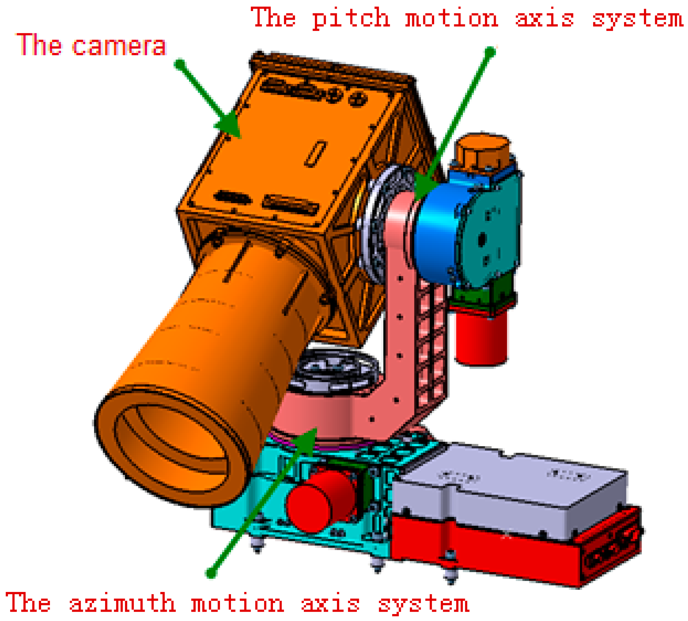
2. Design of Spatial Optoelectronic Scanning Mechanism

As shown in Figure 1, The spatial optoelectronic scanning mechanism mainly consists of a two-dimensional optoelectronic turntable and a camera. The worm and worm gear motion mechanism in this paper is applied to the space optoelectronic scanning turntable, which is mainly composed of a pitch motion axis system, an azimuth motion axis system, and a camera. The driving mechanisms of the pitch motion axis system and the azimuth motion axis system are both worm and worm gear motion mechanisms. The pitch axis system drives the camera to rotate along the pitch axis, while the azimuth axis system drives the camera to rotate along the azimuth axis. This article takes the pitch axis system as an example for analysis and research. Figure 1 shows the composition diagram of the photoelectric scanning turntable, with the pitch axis system at the −20° position. Figure 2 is a diagram of the pitch axis system motion. Communication cables 1, 2, 3, and 4 are installed between the camera and the two-dimensional pointing mechanism bracket, and the installation form of the cables is shown in Figure 3.
The worm and worm gear movement mechanism, as illustrated in Figure 4, mainly consists of the worm, worm gear, angular contact bearings, magnetic steel, magnetic steel seat, stepper motor, and additional components. The stepper motor is connected to the spring through the motor connection seat, and the spring is connected to the worm through the worm gear connection seat, achieving a flexible connection of the stepper motor shaft and protecting the motor. Angular contact bearings are installed at both ends of the worm, which helps stabilize the worm’s rotation and also has a certain limiting effect on its radial and axial jumps.
In order to adapt to the special spatial environment, different metal materials are selected for the worm and worm gear. The worm is made of 2A12-T4 aluminum, and the worm gear is made of 9Cr18 steel. At the same time, the worm is treated with molybdenum disulfide solid lubrication spray coating, and the worm gear is treated with molybdenum disulfide sputtering to increase operational lubrication while avoiding cold welding.
By analyzing the process of worm and worm gear rotation, the stepper motor drives the worm gear to rotate, and the worm gear drives the worm to rotate, thereby driving the camera to rotate. The meshing process of worm and worm gear requires motion clearance. If the clearance is reserved small, there is a risk of jamming. If the clearance is large, it will affect the overall stiffness. In this paper, the initial design of the center distance of the worm gear and worm gear is 0.03–0.06 mm, which can meet both the motion clearance and the overall stiffness requirements.

3. Analysis of the Principle of Micro-Vibration Generation

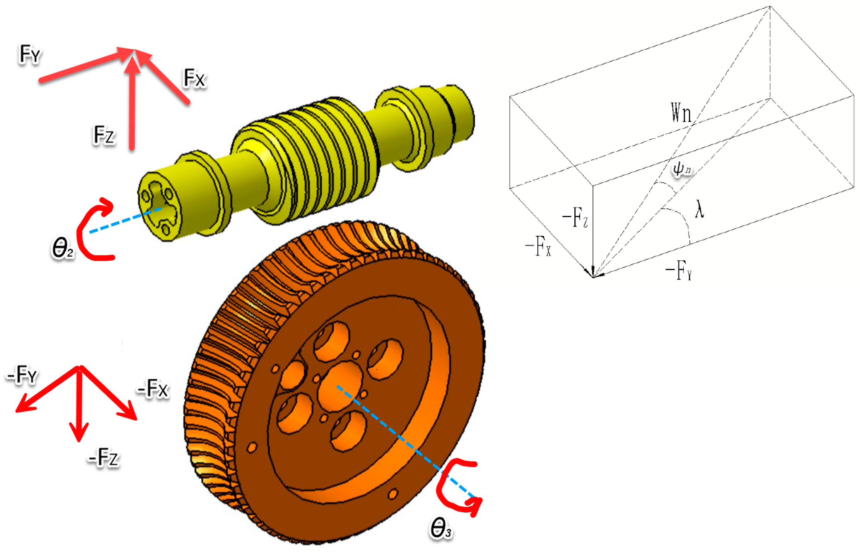
3.1. Dynamic Modeling of Worm and Worm Gear

In order to establish the dynamic model of worm gear, some physical characteristics must be considered. First of all, the parametric excitation due to the meshing stiffness fluctuation and transmission error variations, caused by the tooth elastic deflections, must be included in the model.
The influence of the number of degrees of freedom is significant and cannot be neglected. However, considering profile defects and profile faults should be approached differently. Thus, it is necessary to make a compromise between the simplicity and accuracy of the model. However, the objective of the developed model is to be fast and adaptable to many situations. The authors also compare the amplitudes of the angular acceleration obtained by the models in six and eight degrees of freedom with experimental data obtained by Parey. This validation shows a greater correlation with the results in six degrees of freedom [7,8,22,23].
Comparing with our case (wheel and worm system), we see that the only difference is that in the developed models, the teeth, either the wheel or the pinion, are right, which is to say the angle of inclination is equal to zero, so the contact force on the plane is perpendicular to the axis of rotation. But in the case where the teeth are inclined at an angle (cylindrical worm wheel), the contact force is in the space, which is to say it has three components (following x, y, and z), as is shown in Figure 5 The three components of the contact force (force engagement) will create three translations along x, y, and z (three degrees of freedom) for the worm and three for the wheel. In total, there are eight degrees of freedom. This is the model that will be used for our study, as shown in Figure 5.
To obtain this information, the selected model will be based on a system with a minimum of eight degrees of freedom. The models including a number of degrees of freedom than eight require them to know about details of the frame, the motor, and the load. These data are sometimes difficult to know and model effectively. This is so that the model is not needlessly overloaded.
The model of Figure 6 can be modeled in the form of eight equations, each corresponding to one degree of freedom:
J v θ v ¨ + C t v θ v ˙ + k t v θ v = T m W n [ cos φ n sin λ + u c o s ( λ ) ] R v
J r θ r ¨ + C t r θ r ˙ + k t r θ r   =   W n cos φ n cos λ + u s i n λ R r T c
M v X v ¨ + C v x X ˙ v + k v X X v = F X
M v Y v ¨ + C v Y Y v ˙ + k v Y Y v = F Y
M v Z v ¨ + C v Z Z v ˙ + k v Z Z v = F Z
M r X r ¨ + C r X X ˙ r + k r X X r = F X
M r Y r ¨ + C r Y Y ˙ r + k r Y Y r = F Y
M r Z r ¨ + C r Z Z ˙ r + k r Z Z r = F Z
For instance,
F X = W n cos ( φ n ) sin λ + W f cos λ
F Y = W n cos ( φ n ) cos λ W f sin λ
F Z = W n sin φ n
W f = u W n
Thereafter, writing the equations in the matrix system, we obtain a system of coupled equations where q is the generalized displacement degrees of freedom:
M × q ¨ + C × q ˙ + [ K ] × q = F o r c e ( q , q ˙ )
Thus, by returning to the left, the terms for the variables in Equation (13), we obtain a new system whose force is constant:
M C × q ¨ + C C × q ˙ + [ K C ] × q = F o r c e
The matrices [MC], [CC], and [KC] presented below are the mass matrices, damping, and rigidity of the system, respectively, and indeed show the coupling between the various degrees of freedom. These matrices depend on the following values:
μ : The friction coefficient.
λ : The inclination angle.
φ : The pressure angle of the gear.
J υ and J r : The inertia of the wheel and the worm.
M υ and M r : The weight matrices for the wheel and the worm.
C υ X C υ Y and C υ Z : Damping of the support of the worm following x, y, and z.
C r Y and C r Z : Damping of the support of the wheel following x, y, and z.
K υ X , K υ Y and K υ Z : The rigidities of the supporting worm according to x, y, and z.
K r X ,   K r Y and K r Z : The rigidities of the supporting wheel according to x, y, and z.
The development test bed for vibro-acoustic analysis is based on the dynamic model with 8 DOF and the results of the simulation.

3.2. Micro-Vibration Dynamics Analysis of Worm and Worm Gear Motion Mechanism

A conduct force analysis on the worm and worm gear movement mechanism is performed, selecting four key positions during the movement process and the pitch +90° position, XX° position, YY° position, and −20° position for analysis. The cable deformation and the winding torque are maximum near the +90° and −20° positions, and the direction is opposite. The winding torque is 0 between the XX° and YY° positions. Therefore, a conduct force analysis on the micro-vibration of the worm gear and worm movement in four working conditions is performed (Figure 7).

3.2.1. Camera Runs from+90° to XX°

M(t) is the winding torque, which is a non-linear change over time t. When the pitch reaches XX°, the winding torque is 0; θ is the backlash angle caused by the meshing clearance between the worm and worm gear.
When the camera is in the +90° position, due to the presence of M(t), the meshing relationship between the worm and the worm gear is shown in Figure 8, and the lower end face of the worm teeth contacts the worm gear. At this point, if the driving worm gear is running, the worm is in an upward rotation state. After the contact surface between the worm and the worm gear teeth is separated, due to the presence of the wire winding M(t), the lower end face of the worm teeth will continue to approach the worm gear, causing a collision.
The camera is balanced under wireless cable torque, and during the operation of the camera from +90° to XX°, M(t) is a non-linear change over time t. Due to the rigid connection between the camera and the worm through bearings, the meshing point between the worm and the worm gear also bears M(t) in the same direction. Under the action of M(t), the worm will generate angular acceleration α(t).
M(t)= Jα(t)
θ = α ( t ) t d t
K i n e t i c   e n e r g y : E = 1 2 J ω 2 ( t )
ω ( t ) = d θ d t
K i n e t i c   e n e r g y : E = 1 2 J ω 2 t = 1 2 J ( d θ d t ) 2
ω t = α t d t =   M ( t ) J d t
K i n e t i c   e n e r g y : E = 1 2 J ω 2 t = 1 2 J ( M ( t ) J d t ) 2 =   1 2 J ( M ( t ) d t ) 2
From Formula (15), it can be seen that the camera inertia J is a known parameter, so the larger the line winding M(t), the greater the worm angular acceleration α(t);
From Formula (16), it can be seen that the larger the return angle θ , the greater the angular velocity ω t at time t when M(t) is determined;
According to the kinetic energy formula in Formula (17), the larger the angular velocity ω t , the greater the impact energy at time t;
According to the kinetic energy formula in Formula (19), it can be concluded that under the condition of a constant line around M(t), the larger the return angle of the worm gear θ , the greater the impact energy.
According to the kinetic energy formula in Formula (21), it can be concluded that under a constant return angle, the larger the winding torque M(t), the greater the impact energy.

3.2.2. Camera Runs from XX° to +90°

When the load is at XX° position, due to the presence of M(t), the meshing relationship between the worm and the worm gear is shown in Figure 9, and the lower end face of the worm teeth contacts the worm gear. At this point, if the driving worm gear is running, the worm gear is in a downward rotation state, and the contact surface between the worm and the worm gear teeth cannot be separated. Due to the presence of wire winding M(t), there will be no violent collision.

3.2.3. Camera Runs from −20° to YY°

When the camera is at the −20° position, due to the presence of M(t), the meshing relationship between the worm and the worm gear is shown in Figure 10, and the upper end face of the worm teeth contacts the worm gear. At this point, if the driving worm gear is running, the worm gear is in a downward rotation state. After the contact surface between the worm and the worm gear teeth is separated, due to the presence of the wire winding M(t), the upper end face of the worm teeth will continue to approach the worm gear, causing a severe collision.

3.2.4. Camera Runs from YY° to −20°

When the camera is at the −20° position, due to the presence of M(t), the meshing relationship between the worm and the worm gear is shown in Figure 11, and the upper end face of the worm teeth contacts the worm gear. At this point, if the driving worm gear is running, the worm gear is in an upward rotation state, and the contact surface between the worm and the worm gear teeth cannot be separated. Due to the presence of wire winding M(t), there will be no violent collision.

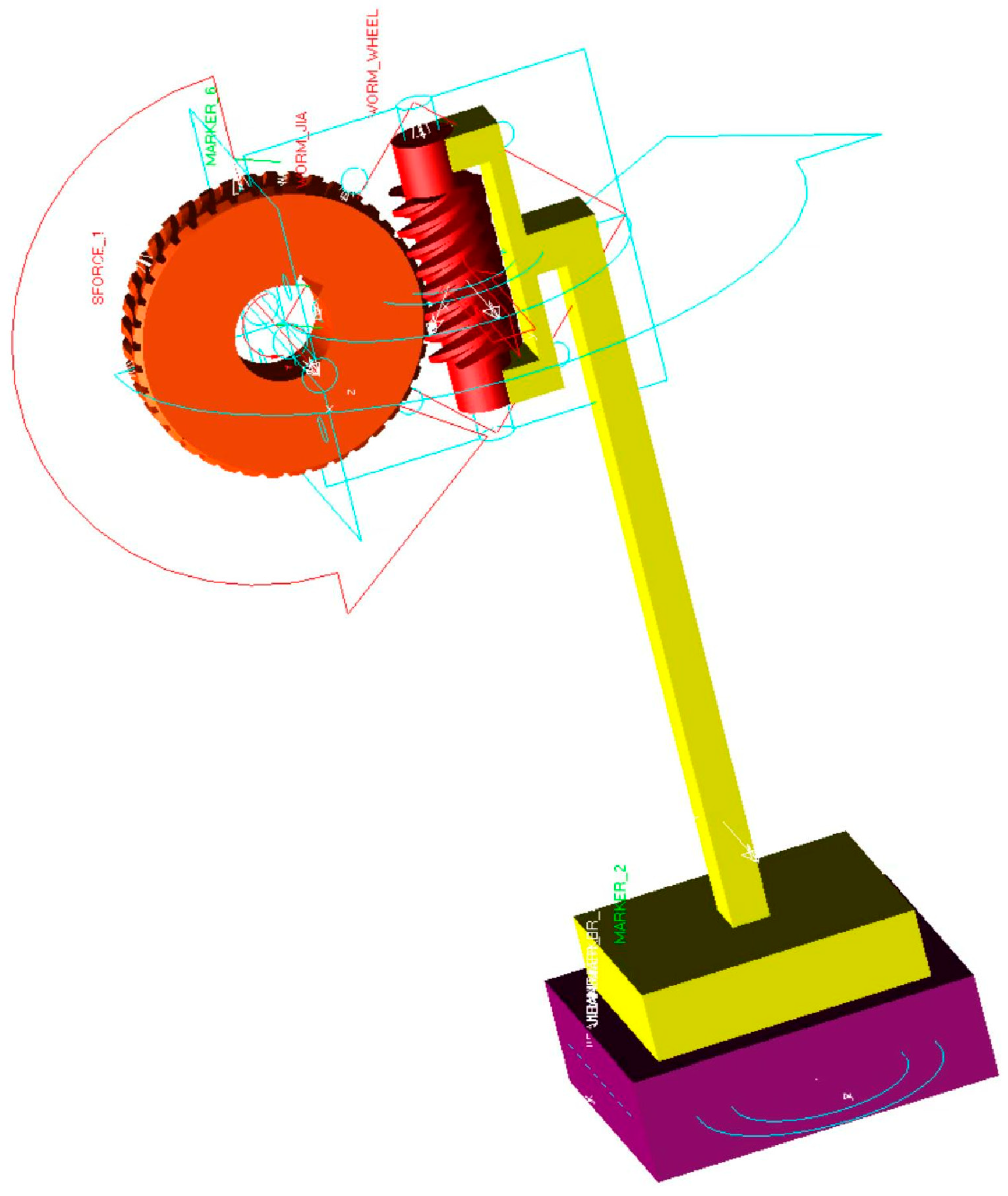
3.3. ADAMS Simulation Analysis of Micro-Vibration in Worm Gear Mechanism Motion

Using Adams 2020 to simulate and analyze the worm gear motion mechanism, the model is first simplified. The simplified model is shown in Figure 12, which mainly consists of the worm gear, worm gear mounting bracket, and base. The force monitoring point is set on the surface of the base to simulate and analyze the two influencing factors of meshing clearance and unbalanced torque, and record the force situation of the monitoring point under different working conditions.
Setting the clearance between the worm gear and worm to 0.1 mm, the worm gear rotation speed to 6°/s, the worm gear transmission ratio to 60, and the simulation time to 5 s, the analysis is performed under two conditions: no interference torque on the worm gear, and the presence of interference torque (0.75 Nm, in the same direction as the motion). The data at the monitoring points are shown in Figure 13. From the simulation results, it can be seen that the worm gear rotated 5 times within 5 s, with 5 peak values, which are the forces generated by the impact during worm gear and worm gear meshing. When there is an interference force, the impact force of the worm gear is about 4 N greater than that without an interference force. The simulation results indicate that an external interference force will increase the vibration force.
Setting the clearance between the worm gear and worm to 0.1 mm and 0.5 mm, the worm gear rotation speed to 6°/s, the worm gear transmission ratio to 60, and the simulation time to 5 s, analyze the condition of no interference torque on the worm gear. The data at the monitoring point is shown in Figure 14. From the simulation results, the worm gear rotates five times within 5 s, producing five peak values, which correspond to the forces generated by the impact during the meshing of the worm and worm gear. The simulation results also indicate that an increase in the clearance between the worm gear and worm gear will lead to an increase in the vibration force.
Through simulation analysis, it has been verified that the clearance between the worm gear and the external unbalanced force (wire-winding torque) is the fundamental cause of micro-vibration.

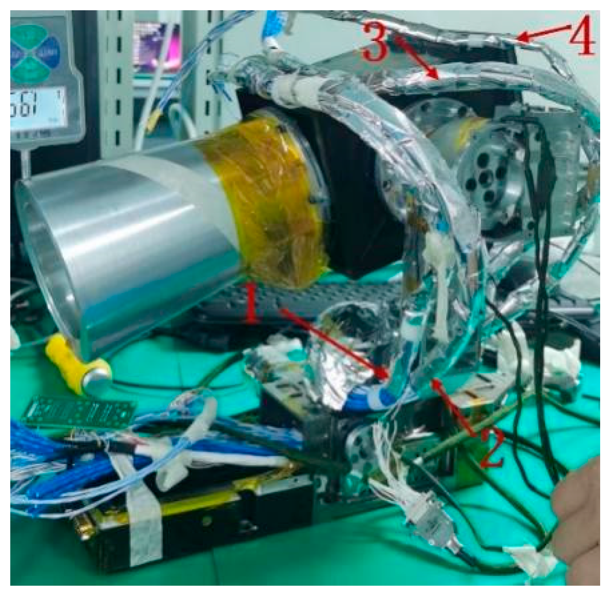
4. Experimental Verification of the Principle of Micro-Vibration Generation

Through the analysis in Section 3, it is found that the excessive meshing clearance of the worm gear and the unbalanced force of the winding are the fundamental causes of micro-vibration. Therefore, this section mainly conducts experimental verification of the above analysis results. The photoelectric scanning turntable is rigidly connected to the turntable micro-vibration testing table for subsequent testing. The micro-vibration testing platform is shown in Figure 15.

4.1. The Influence of Wire-Winding Torque on Micro-Vibration

The meshing clearance of the worm gear is fixed at 0.03 mm. Adjust the installation positions of cables 1, 2, 3, and 4, measure the wire-winding force of the cables under different installation configurations using a tension meter, and record the micro-vibration data under different wire-winding torques using a micro-vibration test bench.
Condition 1: The maximum wire-winding force near the pitch +90° position is 5.38 N, and the maximum near the −20° position is 4.18 N. Driven by a motor, the pitch runs from −20° to +90° and then reverses to−20° to stop. The micro-vibration data of the turntable is tested, and the maximum micro-vibration is 14.2 N, located near the 90° position. The test result is shown in Figure 16.
Condition 2: The maximum wire-winding force is 3.12 N at the pitch +90° position and 2 N at the−20° position. According to the testing method of Condition 1, the maximum micro-vibration is 9.8 N, located at around 90° position. The test result is shown in Figure 17.
Condition 3: The maximum wire-winding force at the +90° position is 1.21 N, and the maximum force at the −20° position is 1.3 N. According to the testing method of Condition 1, the maximum micro-vibration is 7 N, located at the −20° position. The test result is shown in Figure 18.
Condition 4: The cable is removed from the camera, thereby canceling the unbalanced force caused by the wire-winding torque. According to Condition 1, the maximum micro-vibration is 2.5 N, located at the +80° position with the head lowered. The test result is shown in Figure 19.

4.2. The Influence of Worm Gear and Worm Meshing Gap on Micro-Vibration

Set the unbalanced force of the wire winding to a fixed value: a maximum of 3.1 N at the pitch +90° position and 2 N at the −20° position.
Condition 5: When replacing the worm gear and adjusting the meshing clearance to 0.01 mm, it was found that the drive mechanism was not running smoothly. In this case, a micro-vibration test was conducted, and it was found that the micro-vibration data reached about 12 N in the range of 90°~80°, slightly increasing compared to the clearance of 0.03 mm. The test results are shown in Figure 20.
Condition 6: The micro-vibration test data when the meshing clearance is 0.03 mm is shown in Figure 21.
Condition 7: The micro-vibration test data when the meshing clearance is 0.05 mm is shown in Figure 22.

4.3. Experimental Summary

The experimental results are shown in Table 1, under a certain meshing clearance, the larger the wire-winding unbalanced force, the more obvious the micro-vibration. When the unbalanced force of the online winding is fixed and the meshing clearance meets normal operation, the larger the clearance, the more obvious the micro-vibration.

5. Optimization Design of Optoelectronic Scanning Mechanism Structure

Through the above theoretical analysis and experimental verification, it can be concluded that there are two factors that affect the magnitude of micro-vibration: one is the meshing clearance of the worm and worm gear, and the other is the unbalanced torque of the winding. Due to the consideration of the smoothness of worm and worm gear operation, its meshing clearance cannot be infinitely reduced. Through thermodynamic experiments, it has been verified that when the meshing clearance is 0.03 mm, it can ensure smooth operation without jamming. Therefore, only by optimizing the structural form of the photoelectric scanning mechanism can the winding torque during operation be reduced, thereby reducing micro-vibration.
In this article, a dual inner stator shaft system structure is designed, which fixes the inner ring of the bearing and rotates the outer ring of the bearing. While enhancing the strength of the shaft system, it also increases the space for cable threading. After threading the cable that is originally thrown outside the camera, the winding torque will be significantly reduced. Figure 23a shows the structure of the inner rotor, with an inner hole size of 8 mm in the shaft system. Figure 23b shows the structure of the inner stator, with an inner hole size of 30 mm in the shaft system. Both the azimuth axis system and the elevation axis system are designed in the form of internal stator structures, so that cables can pass through the holes of the elevation axis system and then through the holes of the azimuth axis system (shown in Figure 24) and be transmitted to the connectors at the base position.
Taking the pitch axis system as an example, we measure the wire-winding torque after passing through the axis. The maximum wire-winding force measured at the −20° and +90° positions is 6 N, with a force arm of 0.015 m, resulting in a torque of 0.09 Nm. Compared to the original braided cable structure, the wire-winding torque is reduced by 53.8%. The whole machine then undergoes micro-vibration testing. The test results are shown in Figure 25. When the pitch axis runs from −20° to +90° and from +90° to −20°, the highest point of micro-vibration does not exceed 3.5 N. Compared to the 7 N of the braided cable structure, the micro-vibration suppression effect is significant, showing a reduction of 50%.

6. Summary

This article analyzes the principle of micro-vibration generated by a worm gear mechanism and verifies the micro-vibration process through physical verification. The verification results indicate that the micro-vibration amplitude in the worm gear motion mechanism is directly related to the meshing clearance of the worm gear and the magnitude of the external winding torque. To ensure the smooth operation of the worm gear mechanism, the meshing clearance is set to 0.03 mm, and the unbalanced torque of the control wire winding is within 1.5 N. The micro-vibration level can be reduced from 14.5 N (highest point) to 7 N (highest value), achieving a good suppression effect. In addition, by designing a dual inner stator structure, the installation of cables through the shaft can be achieved, and the winding torque can be reduced to 0.9 Nm, thereby reducing micro-vibrations to 3.5 N and producing better suppression effects. This design method has high reference significance for micro-vibration suppression of similar devices in the later stage.

7. Patents

The worm gear and worm meshing relationship measuring device and high-precision control method of the turntable are under patent number ZL 202410375733.7.

Author Contributions

Conceptualization, B.G. and H.Y.; methodology, W.C.; formal analysis, H.W.; investigation, Z.Q. and Y.L.; resources, B.G.; data curation, B.G.; writing—original draft preparation, B.G.; writing—review and editing, B.G. All authors have read and agreed to the published version of the manuscript.

Funding

This research was funded by Light of the West Talent Training Plan of the Chinese Academy of Sciences [No. XAB2021YN14].

Data Availability Statement

The original contributions presented in the study are included in the article, further inquiries can be directed to the corresponding author.

Conflicts of Interest

The authors declare no conflict of interest.

References

  1. Jiao, X.; Zhang, J.; Li, W.; Wang, Y.; Ma, W.; Zhao, Y. Advances in spacecraft micro-vibration suppression methods. Prog. Aerosp. Sci. 2023, 138, 100898. [Google Scholar] [CrossRef]
  2. Li, L.; Wang, L.; Yuan, L.; Zheng, R.; Wu, Y.; Sui, J.; Zhong, J. Micro-vibration suppression methods and key technologies for high-precision space optical instruments. Acta Astronaut. 2020, 180, 417–428. [Google Scholar] [CrossRef]
  3. Addari, D.; Aglietti, G.S.; Remedia, M. Investigating micro-vibration sources modelling. In Proceedings of the 13th European Conference on Spacecraft Structures, Materials & Environmental Testing (ECSSMET), Braunschweig, Germany, 1–4 April 2014. [Google Scholar]
  4. Qian, Y.; Xie, Y.; Jia, J.; Zhang, L. Development of active micro-vibration isolation system for precision space payload. Appl. Sci. 2022, 12, 4548. [Google Scholar] [CrossRef]
  5. Elasha, F.; Ruiz-Cárcel, C.; Mba, D.; Kiat, G.; Nze, I.; Yebra, G. Pitting detection in worm gearboxes with vibration analysis volume. Eng. Fail. Anal. 2015, 42, 366–376. [Google Scholar] [CrossRef]
  6. Vikram, A. A Review on Fault Detection of Gearbox by using Vibration Analysis. Int. J. Innov. Res. Sci. Eng. Technol. 2017, 6, 14627–14633. [Google Scholar]
  7. Ebrahim, E.; Payam, J.; Nasrolah, A.; Majid, H.; Mojtaba, B.; Mohammad Hadi, J.; Ali, Z. Developing an intelligent fault diagnosis of MF285 tractor gearbox using genetic algorithm and vibration signals. Mod. Mech. Eng. 2013, 3, 152–160. [Google Scholar] [CrossRef]
  8. Elforjani, M.; Mba, D.; Muhammad, A.; Sire, A. Condition monitoring of worm gears. Appl. Acoust. 2012, 73, 859–863. [Google Scholar] [CrossRef]
  9. Vähäoja, P.; Lahdelma, S.; Leinonen, J. On the condition monitoring of worm gears Engineering Asset Management. In Proceedings of the 1st World Congress on Engineering Asset Management; Springer: London, UK, 2006; pp. 332–343. [Google Scholar]
  10. Yeh, T.J.; Wu, F.K. Modeling and robust control of worm-gear driven systems. Simul. Model. Pract. Theory 2009, 17, 767–777. [Google Scholar] [CrossRef]
  11. Ma, J. Research on Dynamics Simulation and Vibration Characteristics of Deceleration Mechanism of Steering Gear. Fire Control Command Control 2023, 48, 72–77. [Google Scholar]
  12. Cui, Q.; Wang, Y.Q.; Xia, Y.Z. Modal analysis of worm gear based on ANSYS workbench. J. Jiamusi Univ. 2017, 35, 246–249. [Google Scholar]
  13. Yang, Y.M. Modal analysis of worm gear transmission performance based on finite element method. Electron. Sci. Technol. China 2016, 29, 82–84. [Google Scholar]
  14. Liu, Y.C.; Tian, C.L.; Liu, T.; Kong, F. Modal analysis of prestressed worm gear. Ind. Technol. Innov. 2015, 2, 3–7. [Google Scholar]
  15. Kahraman, A.; Singh, R. Non-linear dynamics of a spur gear pair. J. Sound Vib. 1990, 142, 49–57. [Google Scholar] [CrossRef]
  16. Li, M.; Yang, P.; Zhao, C. Research on Meshing Force Simulation of Worm Transmission Mechanism for Screw Jack Mechanism. Modul. Mach. Tool Autom. Manuf. Tech. 2016, 2, 13–15. [Google Scholar]
  17. Kahraman, K. Planetary Gear Train Dynamics. J. Mech. Des. 1994, 116, 712–720. [Google Scholar] [CrossRef]
  18. Huang, Z.; Ma, J.; Wu, D. Simulation study on contact stress of gear tooth. J. Mech. Transm. 2007, 31, 26–28. [Google Scholar]
  19. Baek, J.H.; Kwak, Y.K.; Kim, S.H. On the frequency bandwidth change of a servo system with a gear reducer due to backlash and motor input woltage. Arch. Appl. Mech. 2003, 73, 367–376. [Google Scholar] [CrossRef]
  20. Liu, R.; Zhang, G.; Gong, L.; Huang, Q. Variable inertial damper and its application in zero-drive gear hobbing machine. Chin. J. Mech. Eng. 2006, 19, 439–441. [Google Scholar] [CrossRef]
  21. Hong, L.; Dhupia, J.S. A time-domain fault detection method based on an electrical machine stator current measurement for planetary gear-sets. In Proceedings of the 2013 IEEE/ASME international Conference on Advanced inteligent Mechatronics, Wollongong, NSW, Australia, 9–12 July 2013; pp. 1631–1636. [Google Scholar]
  22. Benabid, Y.; Mansouri, S. Dynamics study and diagnostics with vibration analysis from worm gear manufactured by reverse engineering techniques. J. Vibroeng. 2016, 18, 4458–4471. [Google Scholar] [CrossRef]
  23. Chung, M.Y.; Shaw, D. Parametric study of dynamics of worm and worm-gear set under suddenly applied rotating angle. J. Sound Vib. 2007, 304, 246–262. [Google Scholar] [CrossRef]
Figure 1. Composition diagram of spatial photoelectric scanning turntable.
Machines 12 00857 g001
Figure 2. Diagram of pitch axis system motion.
Machines 12 00857 g002
Figure 3. Cable installation diagram.
Machines 12 00857 g003
Figure 4. Composition diagram of worm gear and worm motion mechanism. 1—magnetic steel seat, 2—magnetic steel, 3—Hall switch, 4—worm gear end angular contact bearing 1, 5—worm; 6—worm gear end angular contact bearing, 7—spring, 8—motor connection seat, 9—stepper motor, 10—worm gear connection seat, 11—worm gear.
Machines 12 00857 g004
Figure 5. Modeling the contact force in the wheel and worm [22].
Machines 12 00857 g005
Figure 6. Modeling with eight degrees of freedom [22].
Machines 12 00857 g006
Figure 7. Schematic diagram of motion force.
Machines 12 00857 g007
Figure 8. The meshing relationship of worm and worm gear when the pitch axis system is located at +90° position.
Machines 12 00857 g008
Figure 9. The meshing relationship of worm and worm gear when the pitch axis system is located at XX° position.
Machines 12 00857 g009
Figure 10. The meshing relationship of worm and worm gear when the pitch axis system is located at −20°position.
Machines 12 00857 g010
Figure 11. The meshing relationship of worm and worm gear when the pitch axis system is located at YY° position.
Machines 12 00857 g011
Figure 12. Simplified model diagram.
Machines 12 00857 g012
Figure 13. Simulation analysis diagram of unbalanced torque impact.
Machines 12 00857 g013
Figure 14. Simulation analysis diagram of meshing clearance impact.
Machines 12 00857 g014
Figure 15. Outline diagram of micro-vibration testing platform.
Machines 12 00857 g015
Figure 16. Diagram 1 of cable torque influence.
Machines 12 00857 g016
Figure 17. Diagram 2 of cable torque influence.
Machines 12 00857 g017
Figure 18. Diagram 3 of cable torque influence.
Machines 12 00857 g018
Figure 19. Diagram without cable torque.
Machines 12 00857 g019
Figure 20. Test diagram of worm and worm gear mesh clearance 0.01 mm.
Machines 12 00857 g020
Figure 21. Test diagram of worm and worm gear mesh clearance 0.03 mm.
Machines 12 00857 g021
Figure 22. Test diagram of worm and worm gear mesh clearance 0.05 mm.
Machines 12 00857 g022
Figure 23. Diagram of double inner stator structure and cable threading axis. (a) The front sectional view; (b) The reverse sectional view.
Machines 12 00857 g023
Figure 24. Diagram of double inner stator structure.
Machines 12 00857 g024
Figure 25. Micro-vibration test diagram of double inner stator structure.
Machines 12 00857 g025
Table 1. Comparison of test results.
Serial NumberBacklashUnbalanced Force of Wire Winding (N)Micro-Vibration Data (N)
10.03 mm5.4 (+90°), 4.18 (−20°)14.5
20.03 mm3.12 (+90°), 2 (−20°)9.8
30.03 mm1.21 (+90°), 1.3 (−20°)7
40.03 mm03.2
50.01 mm3.12 (+90°), 2 (−20°)12
60.03 mm3.12 (+90°), 2 (−20°)9.8
70.05 mm3.12 (+90°), 2 (−20°)18
Disclaimer/Publisher’s Note: The statements, opinions and data contained in all publications are solely those of the individual author(s) and contributor(s) and not of MDPI and/or the editor(s). MDPI and/or the editor(s) disclaim responsibility for any injury to people or property resulting from any ideas, methods, instructions or products referred to in the content.

