Article

Research on Velocity Feedforward Control and Precise Damping Technology of a Hydraulic Support Face Guard System Based on Displacement Feedback

1
College of Mechanical and Electronic Engineering, Shandong University of Science and Technology, Qingdao 266590, China
2
State Key Laboratory of Mining Disaster Prevention and Control Cofounded by Shandong Province and the Ministry of Science and Technology, Shandong University of Science and Technology, Qingdao 266590, China
3
College of Energy and Mining Engineering, Shandong University of Science and Technology, Qingdao 266590, China
*
Author to whom correspondence should be addressed.
Machines 2024, 12(10), 676; https://doi.org/10.3390/machines12100676
Submission received: 26 August 2024 / Revised: 24 September 2024 / Accepted: 25 September 2024 / Published: 27 September 2024
(This article belongs to the Special Issue Key Technologies in Intelligent Mining Equipment)

Abstract

:
The hydraulic support face guard system is essential for supporting the exposed coal wall at the working face. However, the hydraulic support face guard system approaching the coal wall may cause impact disturbances, reducing the load-bearing capacity of coal walls. Particularly, the hydraulic support face guard system is characterized by a large turning radius when mining thick coal seams. A strong disturbance and impact on the coal wall may occur if the approaching speed is too fast, leading to issues such as rib spalling. In this paper, a feedforward fuzzy PID displacement velocity compound controller (FFD displacement speed compound controller) is designed. The PID controller, fuzzy PID controller, feedforward PID controller, and FFD displacement speed compound controller are compared in terms of the tracking characteristics of the support system and the impact response of the coal wall, validating the controller’s rationality. The results indicate that the designed FFD displacement speed compound controller has significant advantages. This controller maintains a tracking error range of less than 1% for target displacement with random disturbances in the system, with a response adjustment time that is 34% faster than the PID controller. Furthermore, the tracking error range for target velocity is reduced by 8.4% compared to the feedforward PID controller, reaching 13.8%. Additionally, the impact disturbance of the support system on the coal wall is suppressed by the FFD displacement speed compound controller, reducing the instantaneous contact impact between the support plate and the coal wall by 350 kN. In summary, the FFD compound controller demonstrates excellence in tracking responsiveness and disturbance rejection, enhancing the efficacy of hydraulic supports, and achieving precise control over the impact on the coal wall.

1. Introduction

The coal industry is a pivotal national economy and energy security cornerstone. Amidst the accelerating pace of the energy revolution, its role as a primary energy source in China is still anticipated to persist over the long term [1]. Underground disasters may occur in coal mining due to increased mining depth, deviation of roof load, and prolonged exposure of coal walls. According to accident statistics, accidents involving coal wall roof caving and rib spalling are the most severe. They occur frequently and consistently, resulting in a significant number of fatalities [2,3,4]. Therefore, ensuring the safety of mining personnel is an urgent and critical issue for the coal industry to address [5].
From the energy dynamics standpoint, coal wall collapses in working faces predominantly stem from the release of stored deformation energy in response to external perturbations. Furthermore, the principal factors influencing these collapses encompass external perturbations, parameters governing the working face layout, and the geological characteristics of the coal seam within the working face [6,7,8,9,10]. The predominant methods for preventing and controlling coal wall collapses typically involve coal wall grouting reinforcement technologies, careful selection of mining heights, and adding a face guard system for hydraulic support [10,11]. In recent years, with the increasing demands for coal mining efficiency nationwide, high mining height technology is also expected to gradually extend to mines across the countries [12,13]. Furthermore, given that hydraulic support typically already features guard structures and contrasts with the application of grouting reinforcement technology, the addition of a face guard system for hydraulic support controls coal wall collapses and mitigates resource wastage during mining. However, few investigations indicate that the tension damage of the coal wall caused by mine pressure intensifies with an increase in mining height, generating longitudinal or transverse through cracks [14,15,16,17]. As shown in Figure 1, when the coal wall is damaged inside or transverse through cracks are generated, the hydraulic support system inadvertently generates disturbances when supporting the coal wall, resulting in coal wall rib spalling. Thus, analyzing methods for controlling the protective actions of hydraulic support while mitigating external disturbances and suppressing coal wall impacts is imperative for coal wall collapse management.
The hydraulic support face guard control system is a multi-level linkage governed by the hydraulic cylinder. Numerous researchers have successfully integrated control algorithms with hydraulic valve-controlled cylinder systems. The researchers applied these algorithms to address precision control challenges across various systems. Examples include hydraulic support driving systems [18], support robots [19], semi-active hydraulic damping struts for vehicles [20], hydraulic turbine governing systems [21], hydraulic suspension systems [22], drilling robots for rock burst prevention [23], and electrohydraulic propulsion systems for tunnelling machines [24]. However, few studies mention the real-time impact response of the mechanical system and the dynamic performance of the hydraulic system due to the protective action of the hydraulic cylinder during the algorithm-controlled process. Furthermore, few investigations mention that hydraulic support can mitigate the impact by adjusting the face guard strategy when facing coal wall collapses caused by hydraulic support impact disturbances [14,15]. However, these investigations still failed to quantitatively analyze the real-time impact response of the mechanical system and the dynamic performance of the hydraulic system when changing the strategy of the coal wall. Therefore, since the hydraulic support face guard system is a typical example of a mechanical –hydraulic coupling system, the impact response of the support action control on the coal wall must be analyzed through co-simulation.
Given that mining machinery, particularly hydraulic supports, is not considered general machinery, these crucial pieces of equipment for supporting coal walls can cost up to USD 300,000 each. Ren H analyzed the response of a 1:2 scaled hydraulic support model under dynamic impact loads and compared it with the dynamic impact experiment of the entire hydraulic support simulated under the same experimental conditions in ADAMS. It was found that the experimental data and simulation data can mutually verify each other [25]. Meng Z adopted the multi software co-simulation approach to analyze the pose changes of hydraulic supports and to solve the problem of their typical mechanical, electrical, and hydraulic coordination characteristics, which are challenging to simulate [26]. In addition, many researchers have widely applied co-simulation to various problems. For instance, a co-simulation platform utilizing RecurDyn-EDEM-AMESim is presented in [27], offering a precise depiction of the working load of bulldozers. Furthermore, co-simulation analysis methodologies are applicable in systems such as automotive interconnected suspension [28], a heavy hydraulic press [29], and mine hoists [30]. However, the literature addressing the utilization of co-simulation analysis for controlling hydraulic support face guard systems is lacking, including studies that employ ADAMS, AMESim, and Simulink.
Hence, a mechanical–hydraulic co-simulation simulation platform is established in this paper. Initially, AMESim is employed to construct the hydraulic system model. Then, ADAMS establishes the kinematic sub-model of the hydraulic support face guard system. Subsequently, Simulink is utilized to create the interface for data exchange within the mechanical–hydraulic system, establishing a specialized co-simulation analysis platform for hydraulic support systems. Moreover, leveraging this co-simulation analysis platform, an FFD displacement speed compound controller is devised by integrating velocity feedforward and fuzzy PID control. The main goal is attenuating external disturbances and suppressing coal wall impacts, thereby managing coal wall buckling. Finally, the displacement and velocity step tracking performance are compared using co-simulation analysis, as well as the disturbance rejection capability of different controllers. Additionally, the impact of hydraulic support face guard system pressure loss on different controllers is analyzed using AMESim (2020.1 version). ADAMS (2020 version) is used to compare the impact response of face guard actions on the coal wall under different controllers. The outcome yields a controller capable of swiftly and stably controlling the support face guard actions while precisely suppressing coal wall impact.

2. Establishing the Mechanical–Hydraulic Coupling Analysis Model for the Hydraulic Support Face Guard System

2.1. Modelling the Mechanical Sub-Model

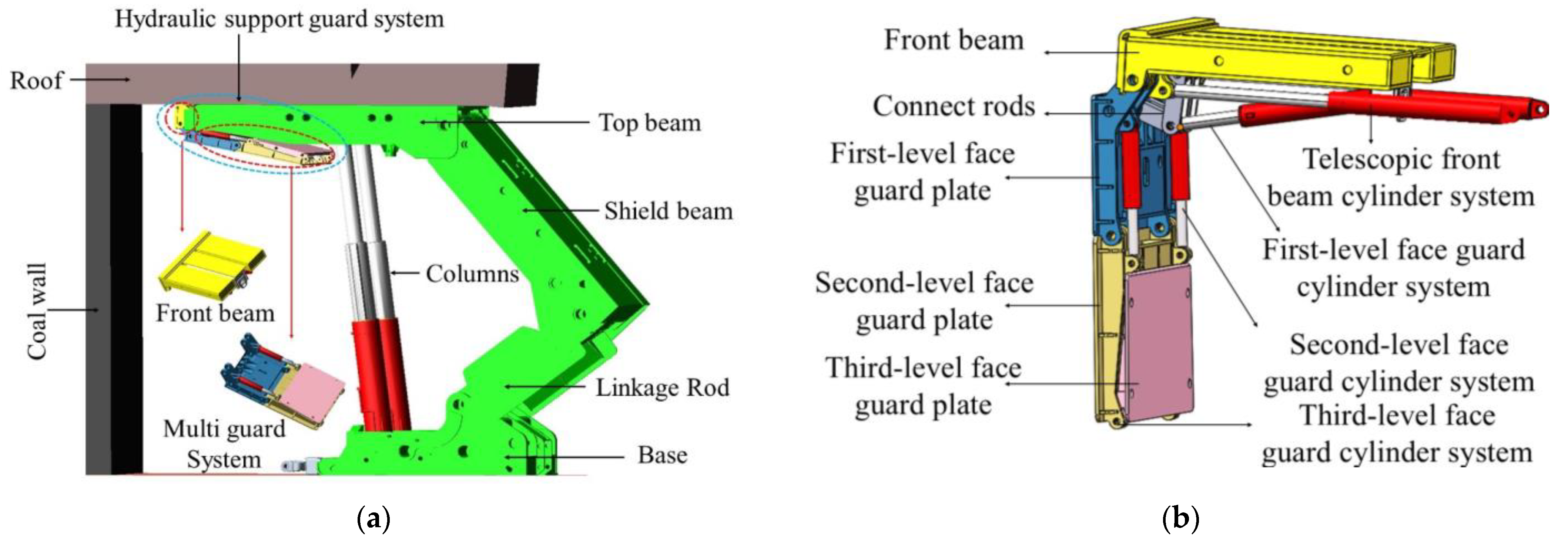
Two primary structural configurations of hydraulic support face guard plates for high-seam mining faces can be found. One is the integral-type face guard plate configuration, while the other is the split-type face guard plate configuration. Compared to the integral configuration, the split-type face guard plate configuration suffers from the disadvantage of a smaller effective face guard area (although the split-type face guard plate configuration offers higher structural strength and stability). Adopting integral-type face guard plates is advantageous for enlarging the protective area [15]. Thus, this paper selects the integral configuration as the research subject and utilizes ADAMS to construct the mechanical sub-model, as illustrated in Figure 2.
As shown in Figure 2, the hydraulic support guard system is an important component of the hydraulic support, primarily responsible for supporting the exposed coal wall after the front section of mining is completed. The operational principle involves the following steps. First, after the shearer passes through the front coal wall of the support, the front beam in the hydraulic support guard system needs to extend promptly to provide the coal wall with timely support. Subsequently, the first-level face guard plate connects with the secondary and tertiary plates to collectively support the coal wall in a continuous manner.

2.2. Modelling the Hydraulic Sub-Model

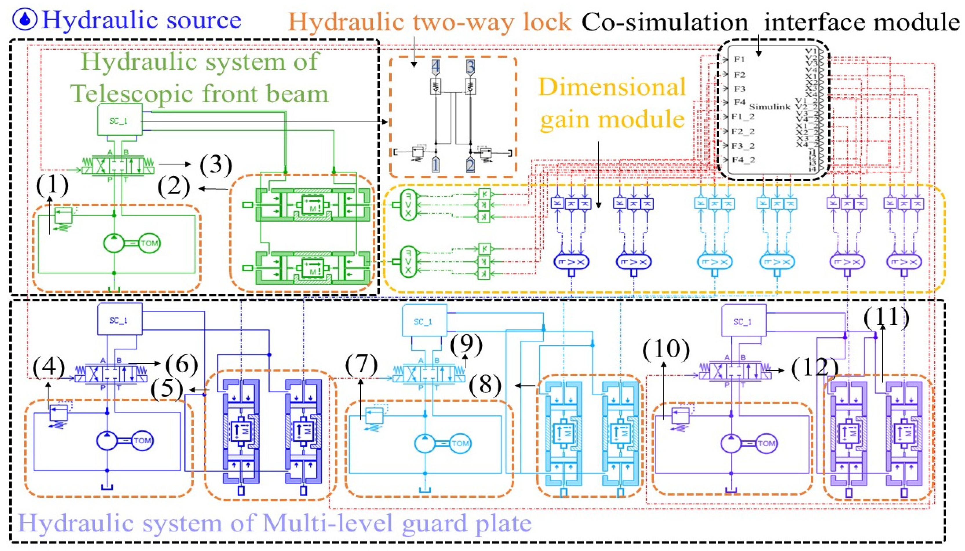
In this study, a hydraulic sub-model of the hydraulic support face guard system is developed using AMESim software (2020.1 version). Hydraulic components include the oil pump, oil tank, electromagnetic directional valve, relief valve, hydraulic bidirectional lock, hydraulic cylinder, and sensors. Dimensional gain factors are introduced due to interaction issues between different software platforms to address dimensional disparities between the software platforms, ensuring stable data transmission among them. The hydraulic schematic diagram is illustrated in Figure 3.

2.3. Static Operation Testing of the Hydraulic Support Face Guard System

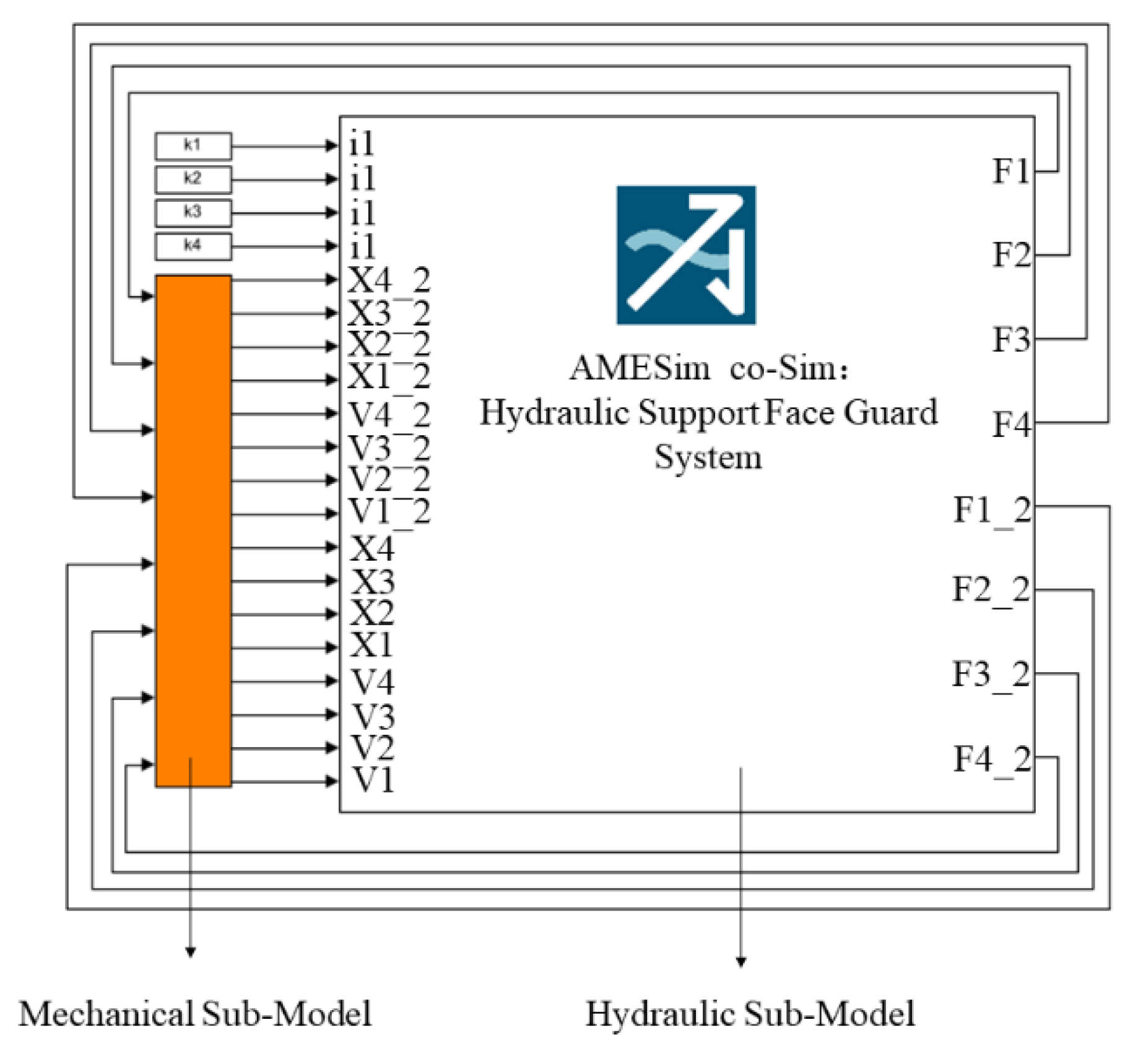
Simulink is utilized to connect the two modules based on the establishment of the mechanical subsystem model and the hydraulic subsystem model. Hence, their data interact in real time to achieve closed-loop control. The co-simulation platform of the hydraulic support face guard system is depicted in Figure 4. The definitions of input and output signals are shown in Table 1.
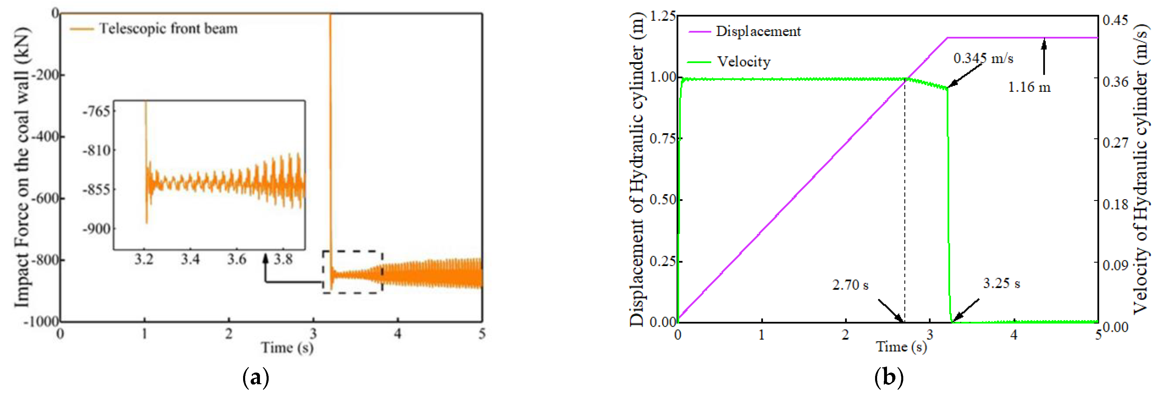
After constructing the co-simulation platform, to test the feasibility of the platform we have built, simplified action testing was conducted on the hydraulic support face guard system. We only allow the front beam to move while keeping all other components stationary, observing the various performances displayed on the platform. The specific settings are shown in Table 2. The gravitational effect of the face guard structure itself was considered, and contact forces were added between the coal wall and each level of the face guard plates during testing. The results are shown in Figure 5 and Figure 6.
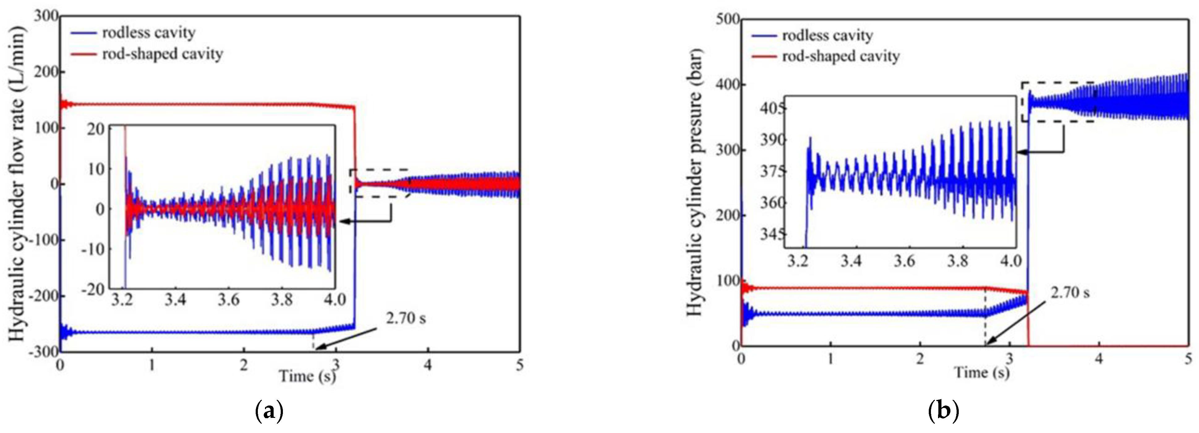
Figure 5 and Figure 6 show that the front beam extends from 0 s to 3.25 s, with pressures in the rod and rodless chambers reaching approximately 95 bar and 50 bar, respectively. The flow rates in the rod and rodless chambers are approximately 145 L/min and 280 L/min, respectively. In contrast, the piston rod of the hydraulic cylinder continues to move at a speed of nearly 0.36 m/s.
As the test progresses to 2.7 s, the flow rate decreases, and the pressure changes due to the gradual deviation of the directional valve from the right position, resulting in the lowest speed of the cylinder dropping to 0.345 m/s. The coal wall and the telescopic front beam come into contact when the telescopic front beam cylinder reaches a displacement of 1.16 m. Here, the coal wall experiences an impact force of up to 890 kN. The cylinder speed drops to 0 m/s with continuous pressurization in the rodless chamber, reaching an internal pressure of 390 bar and a flow rate of 0 L/min. In contrast, the internal pressure in the rod chamber is 0 bar, and the flow rate is 0 L/min.
From 3.25 to 5 s, the telescopic front beam hydraulic cylinder no longer moves forward because it made sufficient contact with the coal wall. Consequently, the internal pressure of the cylinder is established. The internal pressure in the rodless chamber reaches approximately 375 bar. The internal pressure in the rod chamber is 0 bar, and the internal flow rate of the cylinder is roughly 0 L/min.
The above results demonstrate that the co-simulation platform of the hydraulic support face guard system built in this study can accurately reflect the extension process of hydraulic cylinders and the dynamic performance of the hydraulic system. This observation indicates the rationality of the platform construction and the method’s feasibility. Compared to separate simulations of hydraulic or mechanical systems, co-simulation provides a more intuitive representation of the guarding process, yielding more reasonable results.

3. Designing the Face Guard Structure Controller

The hydraulic support system needs to consider the timely support required after the cutting operation of the coal cutter machine and the impact caused by the disturbance to the coal wall. Therefore, the hydraulic support system must act quickly to provide rapid support to the coal wall, minimizing its exposure time after cutting and maintaining its self-supporting rigidity. Simultaneously, the hydraulic support face guard system needs to actively guide the movement speed of the support system to remain close to the coal wall while suppressing the impact disturbance on the coal wall and minimizing the possibility of generating spalling. Hence, devising an appropriate controller within the closed-loop configuration consisting of amplifiers, directional control valves, face guard cylinders, and sensors is imperative to enhance the control dynamics of the face guard system. Hence, superior control efficacy can be achieved.

3.1. Design of Adaptive Fuzzy PID Controller

The advantages of a PID controller in a hydraulic servo system lie in its simple structure and ease of implementation. During the control process, the PID controller processes the error signal proportionally, integrally, and differentially to minimize the error and improve accuracy. The expression is noted as follows:
Δ U ( t ) = K p E ( t ) E ( t 1 ) + K i E ( t ) + K D E ( t ) 2 E ( t 1 ) + E ( t 2 ) ,
U ( t ) = U ( t 1 ) + Δ U ( t ) ,
where K p represents the proportional coefficient, K i represents the integral coefficient, K D represents the differential coefficient, E ( t ) represents the error of the currently controlled physical quantity, and U ( t ) represents the input signal of the currently controlled object. However, the hydraulic support face guard system discussed in this paper is a typical mechanical–hydraulic coupled nonlinear system. Therefore, conventional PID controllers do not exhibit satisfactory control performance. Hence, integrating the fuzzy control approach with the PID controller to form a fuzzy PID controller allows adaptation to a nonlinear system. The design of a suitable fuzzy PID controller includes determining control objectives, as well as defining the fuzzy input and output variables and their membership functions, fuzzy inference, and defuzzification processes [31]. The fuzzy PID controller processes system inputs via fuzzification, transforming them into fuzzy sets. Subsequently, the fuzzy PID controller employs fuzzy rules to map fuzzified inputs to fuzzified outputs, completing the fuzzy inference process. Finally, the controller adopts the centroid method for de-fuzzification to obtain the output result. The inputs of the fuzzy PID controller designed in this study are composed of the error between the target displacement of the telescopic front beam hydraulic cylinder and the first-level face guard hydraulic cylinder and its actual displacement during motion, as well as the rate of change of the error. The outputs of the fuzzy PID controller are composed of k p , k i , and k d . Gaussian-type membership functions are chosen for the endpoints to ensure a rapid response in the central region and smooth transitions at both ends. In contrast, triangular shapes are selected for the middle region. Rules of the fuzzy controller are presented in Table 3.

3.2. Introduction of Feedforward Compensation

Feedforward compensation is a method employed in control systems to enhance performance and stability. This compensation involves predicting disturbances or perturbations in the system and compensating for them before they affect the system, thus reducing response errors [32]. However, the challenge that we faced in speed control in this paper is that when the first-level face guard hydraulic cylinder reaches the target speed, the input signal of the servo valve is close to 0. Due to the input signal of the servo valve being 0, the speed of the hydraulic cylinder will instantly return to 0 instead of the previous target speed. In this case, the speed of the first-level face guard hydraulic cylinder will fluctuate between 0 and the target speed. We consider this error as the error between the target signal and the neutral signal of the servo valve. In order to reduce the impact of error and better control speed, we have introduced speed feedforward compensation. We use the fitting function in MATLAB (R2019b version) to repeatedly fit the speed of first-level hydraulic cylinders under different servo valve signal controls, obtaining a fitting curve between the signal and speed. On the curve, the vertical axis corresponding to each target velocity is the velocity feedforward compensation of the first-level face guard system. The curve is described as follows:
i v = p 1 v 9 + p 2 v 8 + p 3 v 7 + p 4 v 6 + p 5 v 5 + p 6 v 4 + p 7 v 3 + p 8 v 2 + p 9 v + p 10 ,
where i v represents the feedforward compensation of input signal, and v represents the target velocity. The parameters are defined as follows: p 1 = 76,560, p 2 = 399,600, p 3 = 873,900, p 4 = 645,000, p 5 = 725,100, p 6 = 301,400, p 7 = 71,450, p 8 = 8 661, p 9 = 400, and p 10 = 0.06248.
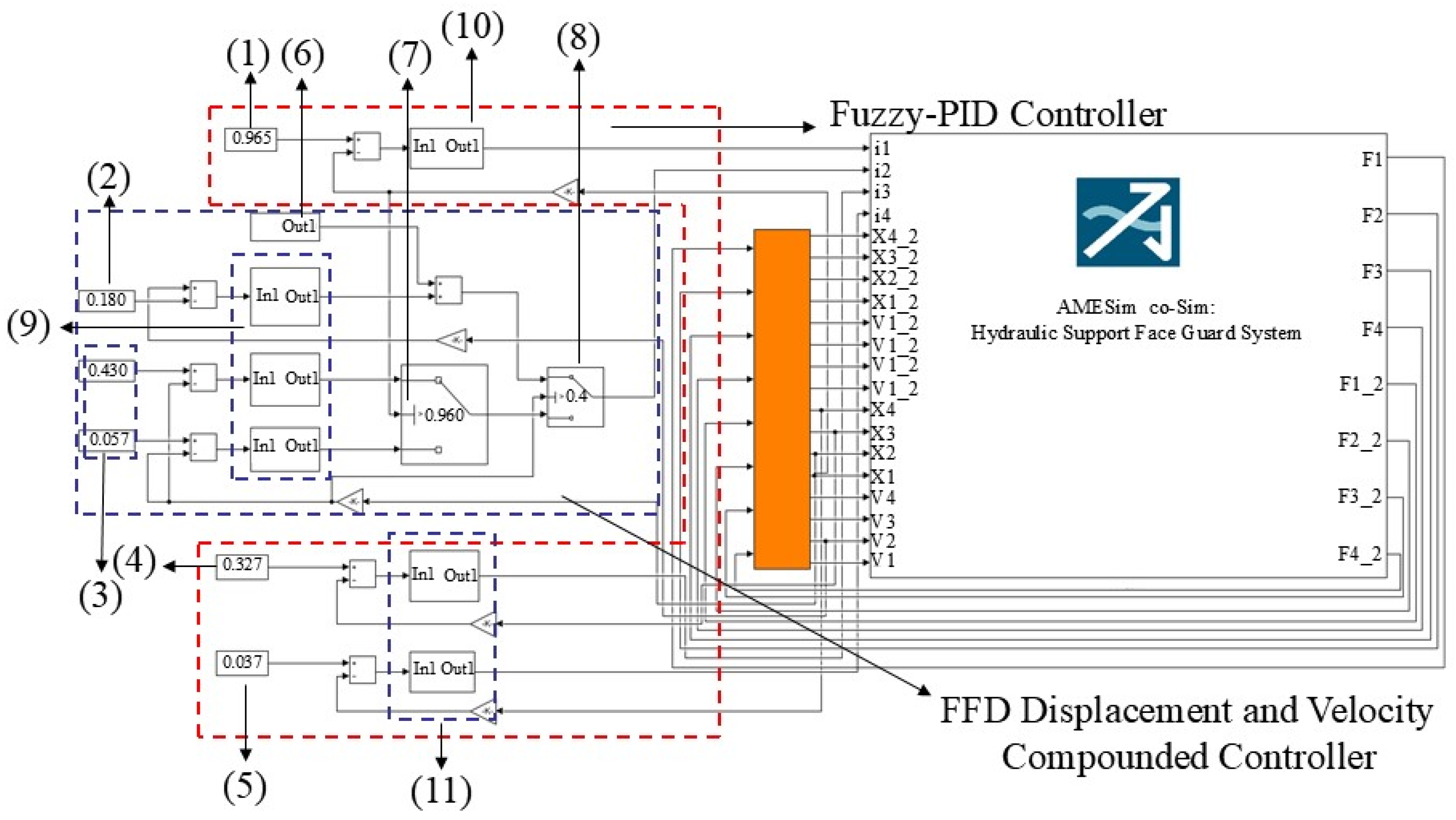
The composite control system for displacement and velocity designed in this study is illustrated in Figure 7.
According to Figure 7, the control comprises the fuzzy PID and the FFD controller modules. The fuzzy PID displacement controller governs the overall movement of the face guard. Just before the end of the guarding process, the controller switches to the FFD controller to fine-tune the movement speed of the guard plates, achieving precise suppression of the coal wall impact. The output data values are as follows:
U ( t ) = x ( t ) v ( t ) a 0 0 b ,
where v ( t ) represents the output of the velocity control module, x ( t ) represents the output of the displacement control module, a represents the proportion of the displacement feedback signal to the total input, and b represents the proportion of the velocity feedback signal to the total input.

4. Simulation Results and Analysis

4.1. Unified Simulation Model

The first-level face guard plate of the hydraulic support is the main component causing the rib spalling of the coal wall due to wall impact [16]. Therefore, the movement of the first-level face guard plate is divided into two stages to address increasing the contact area of the face guard plate with the upper coal wall while reducing the impact of the face guard on the coal wall when the face guard plate is ejected by the hydraulic support.
The first stage uses a fuzzy PID controller to rapidly move the face guard cylinder to approximately 90% of its stroke. The second stage switches the controller to an FFD controller, fine-tuning the action of the face guard and preventing the coal wall from receiving a massive impact, leading to rib spalling. The remaining structure is designed using a fuzzy PID controller to control the overall direction and promptly support the coal wall. As illustrated in Figure 8, the co-simulation platform is predicated on the FFD displacement velocity compound controller.

4.2. Controller Tracking Performance Testing

The density of the coal wall was defined as 500 kg/m3, while the materials of the face guard plates and cylinders were specified as steel. Precise parameters were assigned, while the gravitational effects in the model were aligned with standard gravitational forces along the negative y-axis direction. Timely support must be ensured from the telescopic front beam and the first-level face guard plate due to the decreased stability of the coal wall after mining. Therefore, the specific parameter settings are the same as those in Table 2, except that i1, i2, i3, and i4 are no longer given values but the real-time control signal in Simulink. The telescopic front beam moves first. After it contacts the coal wall, the first-level face guard plate, combined with the second-level face guard plate and the third level-face guard plate, continuously protect the coal wall.
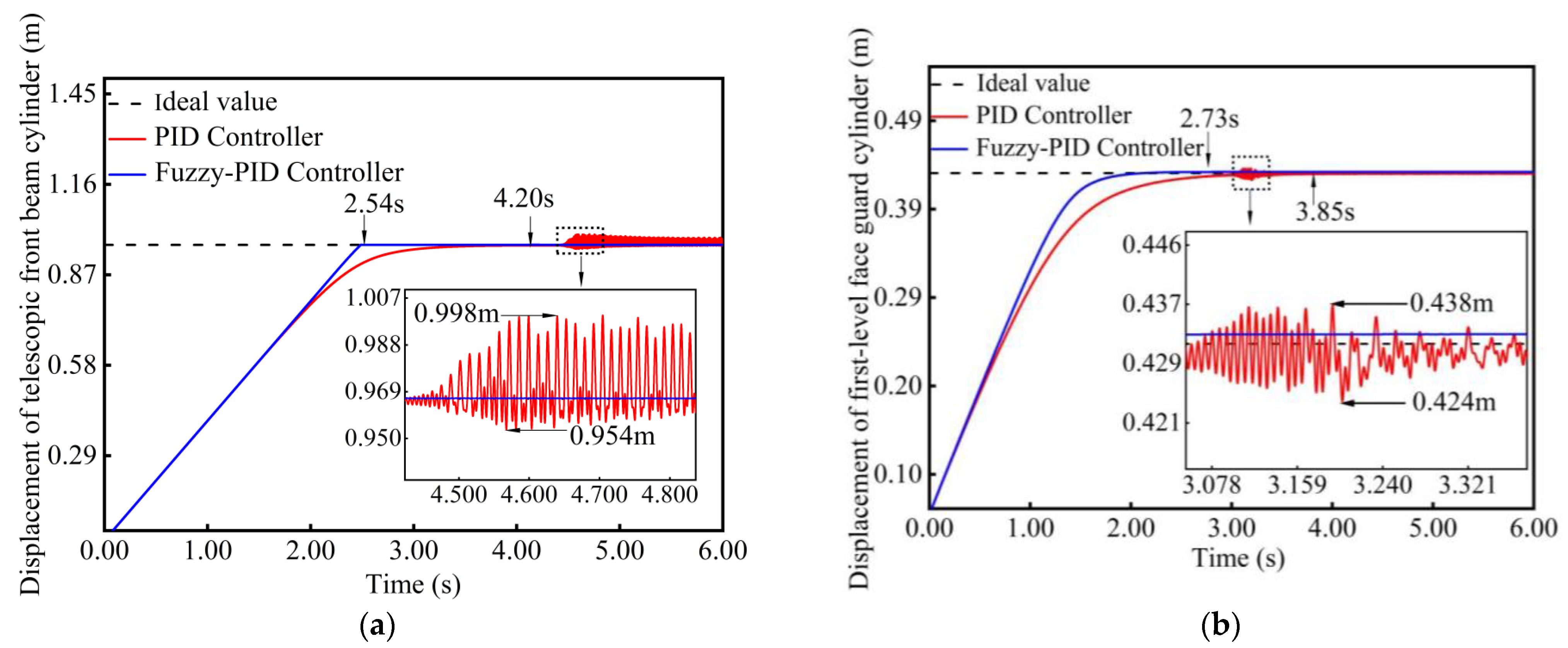
The displacement tracking performance of the telescopic front beam and the first-level face guard cylinder under different controllers is illustrated in Figure 9.
According to Figure 9, compared to the fuzzy PID controller, the tracking error of the hydraulic support face guard structure under the control of the PID controller increases and exhibits pronounced oscillations. The oscillation error of the telescopic beam cylinder ranges from −1.1% to 3.4%, with a settling time of approximately 4.20 s. Moreover, the oscillation error of the first-level face guard cylinder ranges from −1.8% to 1.3%, with a settling time of approximately 3.85 s. In contrast, the fuzzy PID controller can track and stabilize within the target displacement range of ±0.1%, exhibiting a faster settling time than the conventional PID controller and demonstrating significant advantages in controlling step signals.
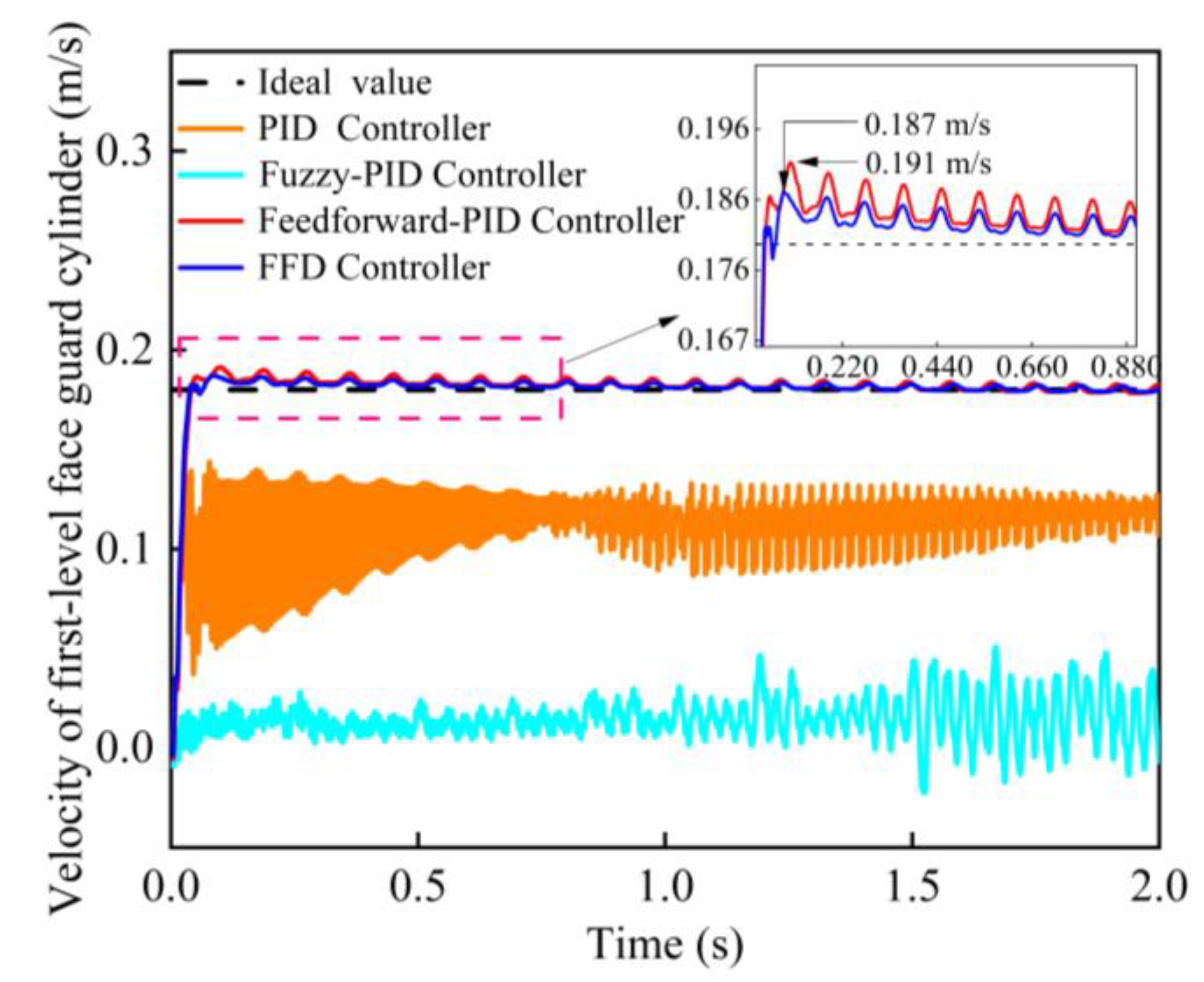
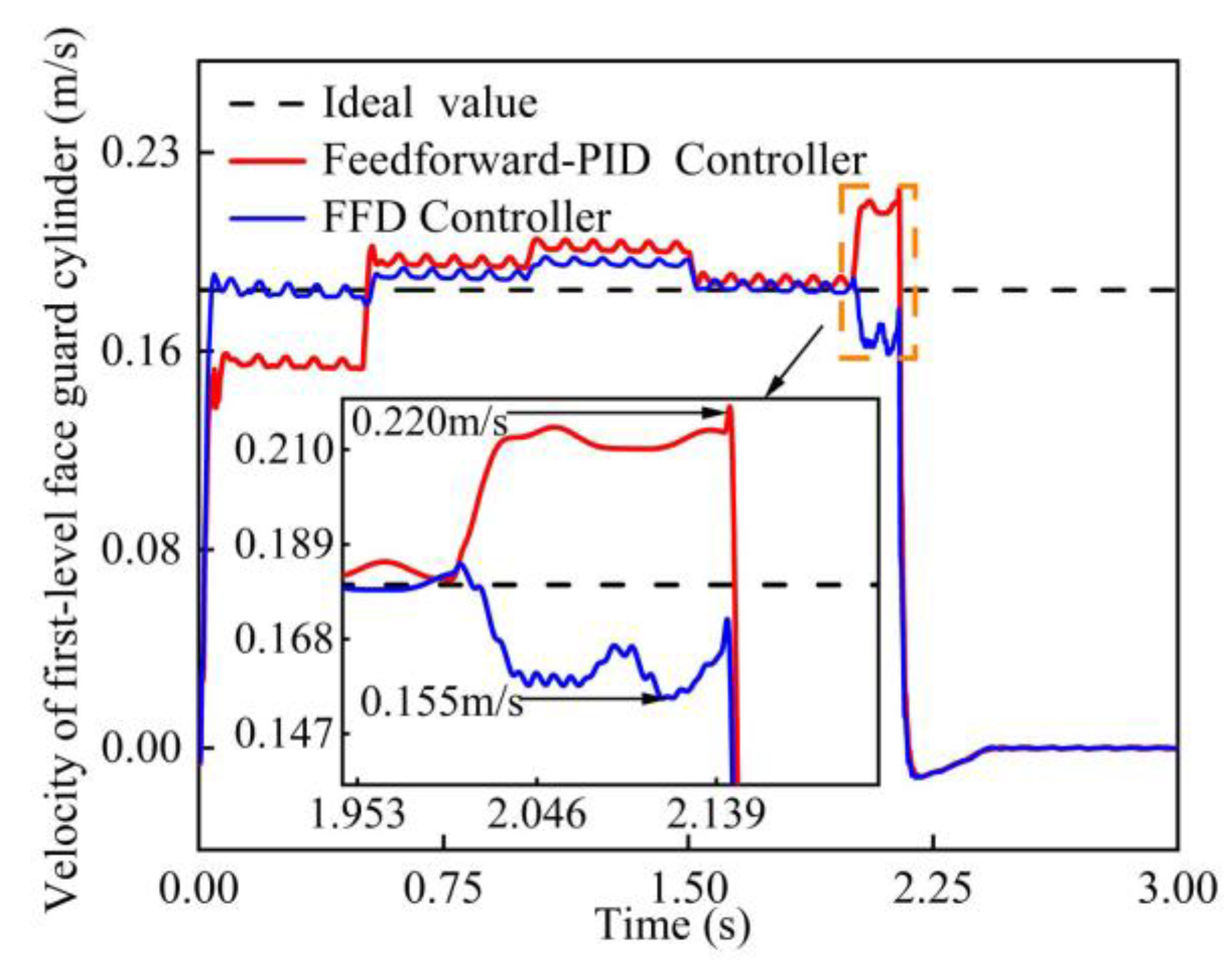
Due to the primary role of the first-level face guard plate in triggering coal wall spalling, this paper only fine-tunes the velocity of the first-level face guard plate during the control of the support canopy action. Figure 10 shows the first-level face guard cylinder’s velocity step response tracking curve under different controllers.
According to Figure 10, the PID and fuzzy PID controllers cannot track the target velocity effectively without feedforward compensation, failing to stabilize the system. In comparison, the feedforward PID controller can track the target velocity curve with an error of 6.1%. On the other hand, the FFD controller maintains the error within 3.8%, reducing it by 2.3% compared to the feedforward PID controller. Its settling time is comparable to that of the feedforward PID controller. Therefore, the FFD controller has an advantage in responding to speed step signals, making it suitable for regulating the approach velocity of the hydraulic support face guard system.

4.3. Controller Disturbance Rejection Performance Test

The working environment in the fully mechanized mining industry is harsh. Numerous disturbance factors can be found when controlling the hydraulic support face guard system, such as the increased impact of falling coal blocks from the roof after mining due to increased mining height. This increase generates sudden displacement and velocity impact disturbances on the support structure. Therefore, the controller must be subjected to disturbance rejection performance tests to verify that the controller can achieve closed-loop control of the cylinder position. The experiment involved applying several random signals as disturbances to the feedback signal once the system reached a steady state (at approximately 4.5 s). Figure 11 and Figure 12 show the controller’s tracking performance under a disturbance.
According to Figure 11, the PID and the fuzzy PID controllers exhibit good tracking performance in response to random disturbances. However, the settling time for the initial wave disturbance is 2.5 s in the telescopic beam hydraulic system controlled by the PID controller, i.e., 34% slower compared to the fuzzy PID controller. Moreover, oscillations occur in the initial disturbance phase. In response to the entire segment of random disturbances, the setting time is 7 s, i.e., 10% slower than the fuzzy PID controller. However, in the first-level face guard hydraulic support system controlled by the PID controller, the response speed to the initial random disturbance is insufficient to reach a steady state. Although it eventually reaches a steady state under subsequent low-disturbance conditions, there is a 0.6% steady-state error. In contrast, the fuzzy PID controller can respond quickly to external disturbances and achieve a steady state without steady-state error. Therefore, the fuzzy PID controller demonstrates significant robustness in the presence of random disturbances in the system, making it more suitable as a displacement controller for hydraulic supports.
According to Figure 12, the FFD controller performs better than the feedforward PID controller under the influence of random disturbances. At approximately 2 s, the controller error reaches its maximum. In this scenario, the maximum error for the feedforward PID controller is approximately 22.2%; for the FFD controller, the maximum is around 13.8%. These values indicate that the FFD controller exhibits better robustness, enabling superior tracking of the target velocity and meeting the requirements of the composite control system.

4.4. Influence of Pressure Loss on the Performance of the Controller

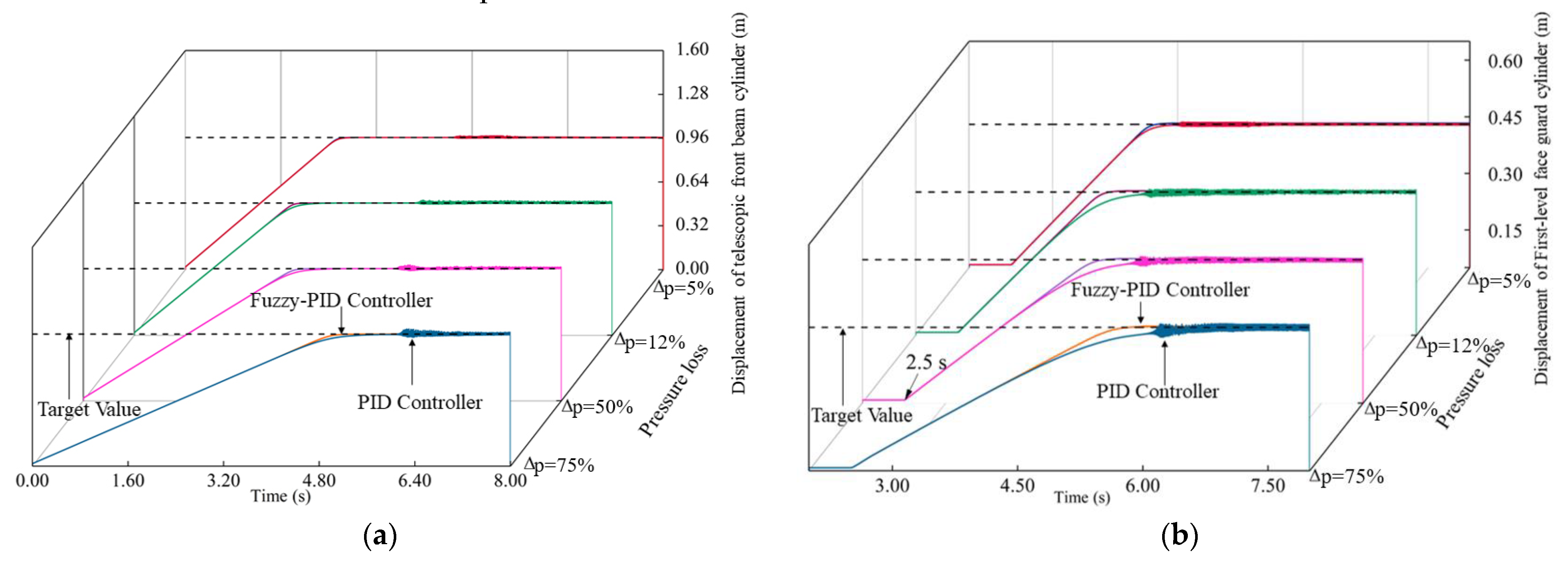
The supply mode of the comprehensive mining face has shifted from traditional close-range supply to centralized supply over longer distances. The long-distance centralized supply technology application improves the efficiency of coal mine excavation work. However, the increasing supply distance leads to pressure loss in the emulsion within the pipelines during transportation. Moreover, the varying distances between each support in the working face and the pump station amplify the pressure difference between each support. Therefore, in this section, the hydraulic component properties are modified in the co-simulation model to compare the tracking characteristics of three controllers under different pump station pressure input loss scenarios of 75%, 50%, 12%, and 5% for step signals. The tracking results are shown in Figure 13, and the comparison of response results is presented in Table 4 and Table 5.
According to the data from the figures and tables, the response time of the hydraulic cylinder of the telescopic beam controlled by the fuzzy PID controller gradually increases with the pressure loss. However, the steady-state error remains within 0.5%. In contrast, for the hydraulic cylinder controlled by the PID controller, the response time increases with pressure loss, and the steady-state error exceeds 0.5%, even reaching 3.8% at higher pressure losses. The system’s average response time is 10% slower than that of the fuzzy PID controller.
For the hydraulic cylinder of the first-level hydraulic support plate, the response time of the fuzzy PID controller increases with the pressure loss. However, the steady-state error remains within 1%. In contrast, the steady-state error exceeds 1% at lower pressure losses for the hydraulic cylinder of the first-level hydraulic support plate controlled by the PID controller. Furthermore, the system’s average response time is 4.7% slower than that of the fuzzy PID controller. In summary, the fuzzy PID controller is more adaptable to pressure loss on-site than the PID controller.

4.5. Analysis of the Coal Wall’s Response to Impact

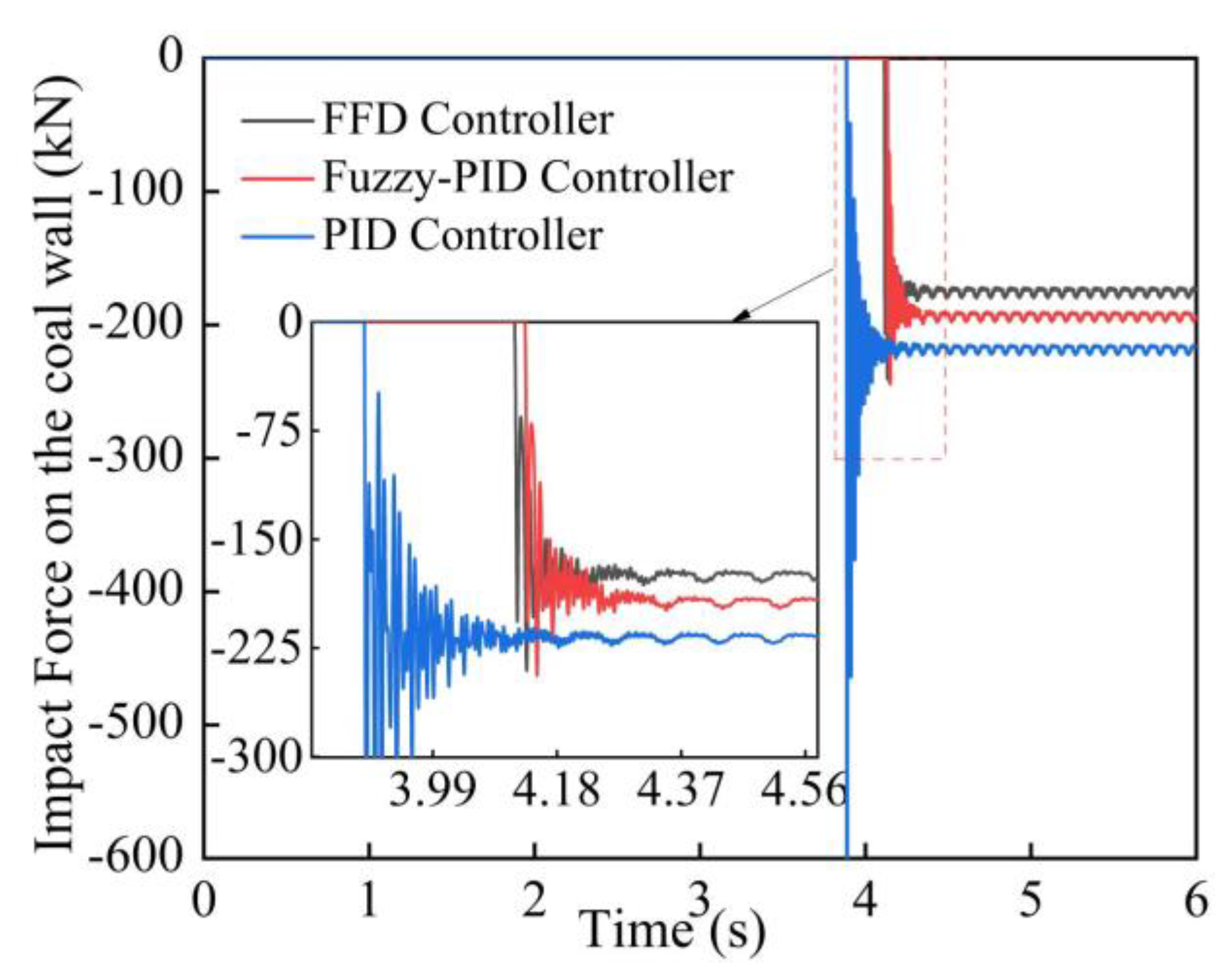
As a typical mechatronic coupled system, hydraulic support undergoes performance testing with various controllers in this study. The contact force between the coal wall and the first-level canopy plate is added to the mechanical model in the joint simulation platform to verify whether the FFD position velocity composite controller can mitigate the impact of the support on the coal wall by controlling the speed of the support approaching the coal wall. The contact type is set to solid-to-solid, damping is set to 10, the friction type is Coulomb friction, the static coefficient is 0.3, and the dynamic coefficient is 0.1. The simulation time is set to 6 s; the results are shown in Figure 14.
According to Figure 14, the impact force exerted by the support frame on the coal wall varies under different controllers. Under the control of the PID controller, the system exhibits oscillations and excessive velocity when contacting the coal wall, resulting in a maximum impact of 600 kN from the support plate (eventually stabilizing at approximately 240 kN). In contrast, the maximum impact of the support plate on the coal wall decreases to 250 kN (ultimately stabilizing at roughly 200 kN) with the introduction of the fuzzy PID controller incorporating fuzzy control, representing a reduction of 350 kN (or 58%) compared to the PID controller. The FFD displacement velocity composite controller causes stabilization at approximately 170 kN, i.e., reduced by 30 kN (or 15%) compared to the fuzzy PID controller. In summary, velocity feedforward compensation on the first-level support cylinder with the fuzzy PID displacement controller successfully reduces the speed of the support plate impacting the coal wall. Therefore, compared to systems without velocity feedforward compensation, the FFD displacement velocity composite controller controls the support action to mitigate the impact response between the coal wall and the support structure. Hence, the rock burst is controlled, providing significant guidance for practical conditions.

5. Conclusions

This paper investigated the FFD displacement speed compound controller for the displacement velocity control system of hydraulic support guard plates. The following conclusions are drawn:
(1)
During the hydraulic support guard process, the fuzzy PID controller demonstrates better robustness than the PID controller when input pressure is lost. Moreover, the fuzzy PID controller exhibits stronger resistance to disturbances and faster response speed in addressing step targets, making it suitable as a displacement controller for the support. However, neither the fuzzy PID controller nor the PID controller can achieve target speed tracking. The fuzzy PID controller requires the introduction of feedforward compensation to correct errors and achieve speed tracking. The test results indicate that the FFD displacement speed compound controller has more advantages in responding to speed step signals than the fuzzy PID and PID controllers. Since the FFD displacement speed compound controller can track the target speed, it can be used as the velocity controller for the support.
(2)
The combined simulation can replicate the working characteristics of the support structure and output the physical features of the mechanical coupling system under the controller. When using the PID controller to control the support movement, the maximum impact response on the coal wall reached up to 600 kN, ultimately stabilizing at approximately 240 kN. When employing the fuzzy PID controller, the maximum impact response on the coal wall reaches 250 kN, ultimately stabilizing at approximately 200 kN. Moreover, with the FFD displacement speed compound controller, the maximum impact response on the coal wall was reduced to 250 kN, stabilizing at 170 kN. These values represent a reduction of 58% from the highest impact response and a minimum reduction of 15%. The results demonstrated that the FFD displacement speed compound controller can mitigate the impact of coal wall response by controlling the approach speed of the support plate.
In conclusion, the FFD displacement speed compound controller, which combines the fuzzy PID displacement controller with the FFD velocity controller, regulates the movement of the support plate. This controller ensures the rapid and stable deployment of the support plate and facilitates a smooth and gradual approach to the coal wall during contact, reducing the impact on the coal wall and preventing rib spalling. A physical platform will be constructed to validate the controller’s experimental performance in future work. Further controller optimization will also be carried out to address real-world application challenges.

Author Contributions

Conceptualization, Q.Z.; methodology, Z.M.; software, Y.H. and L.W.; validation, Y.H.; formal analysis, Y.H.; data curation, Z.M.; writing—original draft preparation, Y.H.; writing—review and editing, Y.H. and L.W.; investigation, Z.M.; resources, Z.M. and Q.Z.; supervision, Q.Z. and Z.M.; project administration, Y.H.; funding acquisition, Q.Z. and Z.M. All authors have read and agreed to the published version of the manuscript.

Funding

This research was funded by the National Natural Science Foundation of China (52104164, 52274132, 52474175 and U23A20599).

Data Availability Statement

The data can be obtained upon reasonable request from the corresponding author.

Conflicts of Interest

The authors declare no conflict of interest.

References

  1. Li, Y.; Li, Z. Forecasting of Coal Demand in China Based on Support Vector Machine Optimized by the Improved Gravitational Search Algorithm. Energies 2019, 12, 2249. [Google Scholar] [CrossRef]
  2. Sears, M.M.; Rusnak, J.; Van Dyke, M.; Rashed, G.; Mohamed, K.; Sloan, M. Coal Rib Response during Bench Mining: A Case Study. Int. J. Min. Sci. Technol. 2018, 28, 107–113. [Google Scholar] [CrossRef]
  3. Singh, S.K.; Agrawal, H.; Singh, A.P. Rib Stability: A Way Forward for Safe Coal Extraction in India. Int. J. Min. Sci. Technol. 2017, 27, 1087–1091. [Google Scholar] [CrossRef]
  4. Mangal, A.; Paul, P.S. Rock Mechanical Investigation of Strata Loading Characteristics to Assess Caving and Requirement of Support Resistance in a Mechanized Powered Support Longwall Face. Int. J. Min. Sci. Technol. 2016, 26, 1081–1087. [Google Scholar] [CrossRef]
  5. Wang, H.; Liu, Y.; Tang, Y.; Gong, H.; Xu, G. Failure Mechanisms and the Control of a Longwall Face with a Large Mining Height within a Shallow-Buried Coal Seam. Shock Vib. 2021, 2021, e8494913. [Google Scholar] [CrossRef]
  6. Wang, J.; Zhang, Q.; Zhang, J.; Liu, H.; Zhu, G.; Wang, Y. Study on the Controller Factors Associated with Roof Falling and Ribs Spalling in Deep Mine with Great Mining Height and Compound Roof. Eng. Fail. Anal. 2021, 129, 105723. [Google Scholar] [CrossRef]
  7. Lei, W.; Li, X.; Du, W.; Zhang, J.; Zhang, J.; Shang, F.; Xu, T. Research on Mechanism and Prevention Technology of Rib Spalling in Fully-Mechanized Coal Mining Face with Soft and Unstable Seam. IOP Conf. Ser. Earth Environ. Sci. 2019, 252, 052065. [Google Scholar] [CrossRef]
  8. Li, X.; Zhang, X.; Shen, W.; Zeng, Q.; Chen, P.; Qin, Q.; Li, Z. Research on the Mechanism and Control Technology of Coal Wall Sloughing in the Ultra-Large Mining Height Working Face. Int. J. Environ. Res. Public Health 2023, 20, 868. [Google Scholar] [CrossRef]
  9. Bai, Q.-S.; Tu, S.-H.; Chen, M.; Zhang, C. Numerical Modeling of Coal Wall Spall in a Longwall Face. Int. J. Rock Mech. Min. Sci. 2016, 88, 242–253. [Google Scholar] [CrossRef]
  10. Liu, H.; Chen, Y.; Han, Z.; Liu, Q.; Luo, Z.; Cheng, W.; Zhang, H.; Qiu, S.; Wang, H. Coal Wall Spalling Mechanism and Grouting Reinforcement Technology of Large Mining Height Working Face. Sensors 2022, 22, 8675. [Google Scholar] [CrossRef]
  11. Cui, F.; Zhang, T.; Cheng, X. Research on Control of Rib Spalling Disaster in the Three-Soft Coal Seam. Shock Vib. 2021, 2021, 2404218. [Google Scholar] [CrossRef]
  12. Kumar, R.; Singh, A.K.; Mishra, A.K.; Singh, R. Underground Mining of Thick Coal Seams. Int. J. Min. Sci. Technol. 2015, 25, 885–896. [Google Scholar] [CrossRef]
  13. Verma, A.K.; Deb, D. Numerical Analysis of an Interaction between Hydraulic-Powered Support and Surrounding Rock Strata. Int. J. Geomech. 2013, 13, 181–192. [Google Scholar] [CrossRef]
  14. Wan, L.; Zhang, S.; Meng, Z.; Xie, Y. Analysis of the Protection Performance of Face Guard for Large Mining Height Hydraulic Support. Shock Vib. 2021, 2021, 6631017. [Google Scholar] [CrossRef]
  15. Xu, Y.X.; Wang, G.F.; Li, M.Z.; Xu, Y.J.; Han, H.J.; Zhang, J.H. Investigation on coal face slabbed spalling features and reasonable control at the longwall face with super large cutting height and longwall top coal caving method. J. China Coal Soc. 2021, 46, 357–369. [Google Scholar] [CrossRef]
  16. Xu, Y.; Wang, G.; Li, M.; Xu, Y.; Zhou, C.; Zhang, J. Mechanism of slabbed spalling failure of the coal face in fully mechanized caving face with super large cutting height. J. Min. Saf. Eng. 2021, 38, 19–30. [Google Scholar] [CrossRef]
  17. Dong, S. Characteristics and Stability Control of Coal Rib Spalling in Large Mining Height Working Face. China Mine Eng. Ing 2023, 52, 50–54. [Google Scholar] [CrossRef]
  18. Wang, Y.; Zhao, J.; Wang, H.; Ding, H. Output Feedback Control for the Driving Cylinder of Hydraulic Support with Error Constraint. J. Vib. Control 2023, 29, 3126–3136. [Google Scholar] [CrossRef]
  19. Ma, T.; Guo, X.; Su, G.; Deng, H.; Yang, T. Research on Synchronous Control of Active Disturbance Rejection Position of Multiple Hydraulic Cylinders of Digging-Anchor-Support Robot. Sensors 2023, 23, 4092. [Google Scholar] [CrossRef]
  20. Wang, D.-Y.; Zhang, W.-C.; Zeng, X.-G. Investigation on a Semi-Active Hydraulic Damping Strut to Reduce Vehicle in Situ Shift Vibration. J. Vib. Control 2020, 26, 3–18. [Google Scholar] [CrossRef]
  21. Tian, Y.; Wang, B.; Chen, P.; Yang, Y. A State Estimator-Based Nonlinear Predictive Control for a Fractional-Order Francis Hydraulic Turbine Governing System. J. Vib. Control 2020, 26, 1068–1080. [Google Scholar] [CrossRef]
  22. Gu, J.; Xue, X.; Yang, W.; Lu, G. A Hybrid Sliding Mode Controller Design for Vibration Suppression in a Hydraulic Suspension System with Vertical Load Disturbance. J. Vib. Control 2024, 30, 377–391. [Google Scholar] [CrossRef]
  23. Gu, J.; He, S.; Dai, J.; Wei, D.; Yan, H.; Tan, C.; Wang, Z.; Si, L. A Walking Trajectory Tracking Control Based on Uncertainties Estimation for a Drilling Robot for Rockburst Prevention. Machines 2024, 12, 298. [Google Scholar] [CrossRef]
  24. Wu, W.; Gong, G.; Chen, Y.; Zhou, X. Performance Analysis of Electro-Hydraulic Thrust System of TBM Based on Fuzzy PID Controller. Energies 2022, 15, 959. [Google Scholar] [CrossRef]
  25. Ren, H.; Zhang, D.; Gong, S.; Zhou, K.; Xi, C.; He, M.; Li, T. Dynamic Impact Experiment and Response Characteristics Analysis for 1:2 Reduced-Scale Model of Hydraulic Support. Int. J. Min. Sci. Technol. 2021, 31, 347–356. [Google Scholar] [CrossRef]
  26. Meng, Z.; Zeng, Q.; Wan, L. Pose Adjusting Simulation of Hydraulic Support Based on Mechanical-Electrical-Hydraulic Coordination. Teh. Vjesn. 2018, 25, 1110–1118. [Google Scholar] [CrossRef]
  27. Zhu, X.; Pan, L.; Sun, Z.; Wan, Y.; Huang, Y.; Choi, J.-H. Simulation Tool for Dozer Data Acquisition. Autom. Constr. 2022, 142, 104522. [Google Scholar] [CrossRef]
  28. Chen, Z.; Fei-Xiang, X.; De-Qiang, C. A Multi-Objective Optimization Method for Hydraulically Interconnected Suspension System. Proc. Inst. Mech. Eng. Part D J. Automob. Eng. 2024, 238, 1234–1248. [Google Scholar] [CrossRef]
  29. Wang, W.; Du, D.; Wu, R.; Yuan, C.; Chang, B. Co-Simulation Research of the Balancing Control of the Moving Beam of a Heavy Hydraulic Press During the Die Forging Process. In Proceedings of the ASME 2017 12th International Manufacturing Science and Engineering Conference, Los Angeles, CA, USA, 4–8 June 2017. [Google Scholar]
  30. Ziyu, S.; Xiaona, W.; Yajing, L.; Yu, G.; Huimin, H.; Jiahai, H. Co-Simulation Model Coupling of Flexible Rope Hoisting System and Hydraulic Braking System for a Mine Hoist. Proc. Inst. Mech. Eng. Part E J. Process. Mech. Eng. 2022, 236, 881–893. [Google Scholar] [CrossRef]
  31. Ananthamoorthy, N.P.; Baskaran, K. High Performance Hybrid Fuzzy PID Controller for Permanent Magnet Synchronous Motor Drive with Minimum Rule Base. J. Vib. Control 2015, 21, 181–194. [Google Scholar] [CrossRef]
  32. Jensen, K.J.; Ebbesen, M.K.; Hansen, M.R. Adaptive Feedforward Control of a Pressure Compensated Differential Cylinder. Appl. Sci. 2020, 10, 7847. [Google Scholar] [CrossRef]
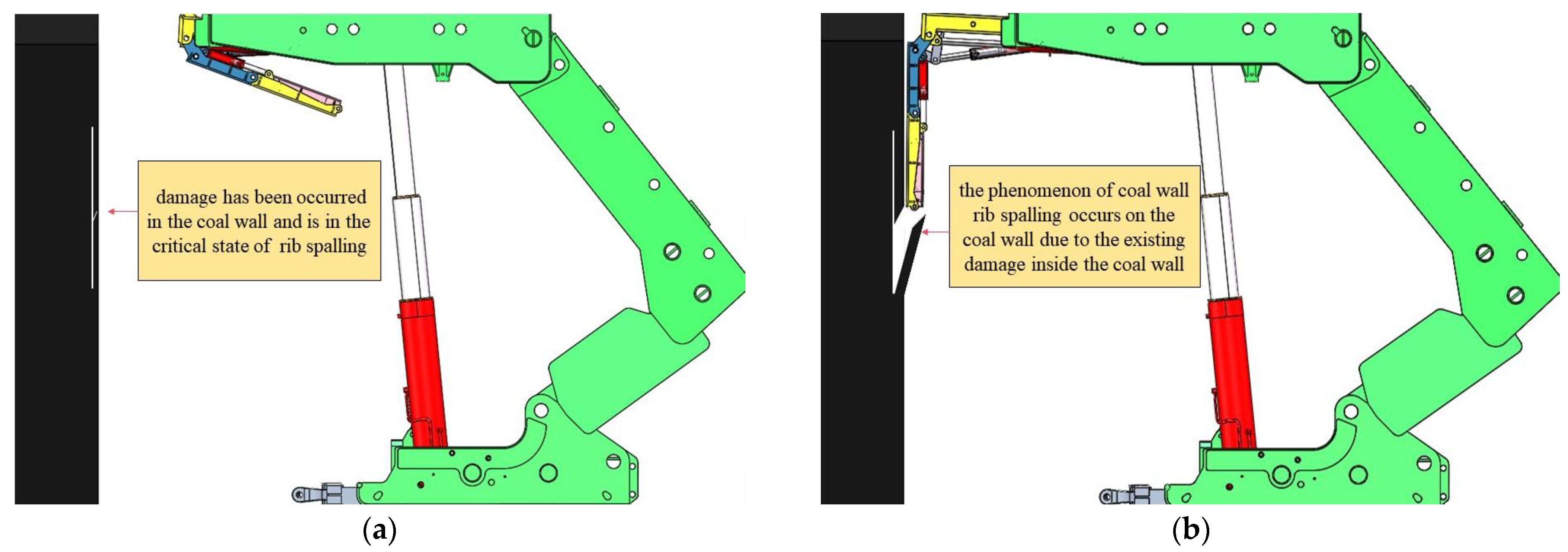
Figure 1. Schematic of a coal wall hit by a hydraulic support face guard system: (a) Damage has occurred in the coal wall; (b) Coal wall spalled due to the disturbance of the hydraulic support system.
Machines 12 00676 g001
Figure 2. Mechanical model: (a) Hydraulic support mechanical model; (b) Hydraulic support guard system mechanical model.
Machines 12 00676 g002
Figure 3. AMESim hydraulic system interface: (1) Oil tank and pump station of the telescopic front beam hydraulic system, (2) Telescopic front beam cylinder system, (3) Hydraulic servo valve of the telescopic front beam hydraulic system, (4) Oil tank and pump station of the first-level face guard plate hydraulic system, (5) First-level face guard cylinder system, (6) Hydraulic servo valve of the first-level face guard plate hydraulic system, (7) Oil tank and pump station of the second-level face guard plate hydraulic system, (8) Second-level face guard cylinder system, (9) Hydraulic servo valve of the second-level face guard plate hydraulic system, (10) Oil tank and pump station of the third-level face guard plate hydraulic system, (11) Third-level face guard cylinder system, and (12) Hydraulic servo valve of the third-level face guard plate hydraulic system.
Machines 12 00676 g003
Figure 4. Hydraulic support face guard system co-simulation platform.
Machines 12 00676 g004
Figure 5. Hydraulic performance of the front beam: (a) Flow rate variation curve of the rod and rodless chambers of the front beam; (b) Pressure variation curve of the rod and rodless chambers of the front beam.
Machines 12 00676 g005
Figure 6. Mechanical performance of the front beam: (a) Response curve of the coal wall to the impact; (b) Pressure variation curve of the rod and rodless chambers of the front beam.
Machines 12 00676 g006
Figure 7. Principal diagram of the FFD displacement velocity composite controller.
Machines 12 00676 g007
Figure 8. Co-simulation platform based on the FFD displacement velocity compound controller: (1) Target displacement of the telescopic front beam hydraulic cylinder, (2) Target velocity of the first-level face guard hydraulic cylinder, (3) Target displacement of the first-level face guard hydraulic cylinder, (4) Target displacement of the second-level face guard hydraulic cylinder, (5) Target displacement of the third-level face guard hydraulic cylinder, (6) Feedforward compensation module, (7) Action switch of the first-level face guard hydraulic cylinder, (8) Velocity control switch of the first-level face guard hydraulic cylinder, (9) Main module of the FFD compounded controller applied to the first-level face guard hydraulic cylinder, (10) Main module of the fuzzy PID controller applied to the telescopic front beam hydraulic cylinder, and (11) Main module of the fuzzy PID controller applied to the second-level face guard hydraulic cylinder and third-level face guard hydraulic cylinder.
Machines 12 00676 g008
Figure 9. Response tracking curves of cylinder displacement under different controllers: (a) Response curve of the telescopic front beam cylinder; (b) Response curve of the first-level canopy cylinder.
Machines 12 00676 g009
Figure 10. Response tracking curves of cylinder velocity under different controllers.
Machines 12 00676 g010
Figure 11. Controller displacement response tracking curve under a random disturbance: (a) Response curve of the telescopic beam cylinder under a random disturbance; (b) Response curve of the first-level face guard hydraulic cylinder under a random disturbance.
Machines 12 00676 g011
Figure 12. Controller velocity response tracking curve under random disturbances.
Machines 12 00676 g012
Figure 13. Displacement tracking curves for the hydraulic cylinder systems under different pressure losses and controller conditions: (a) Displacement of the telescopic front beam cylinder system; (b) Displacement of the first-level face guard cylinder system.
Machines 12 00676 g013
Figure 14. Response curves of different controllers for the coal wall’s reaction to impact.
Machines 12 00676 g014
Table 1. The interpretation of input and output signals.
SignalsMarkInterpretation
Input signalsi1Input signal of the hydraulic servo valve of the telescopic front beam hydraulic system
i2Input signal of the hydraulic servo valve of the first-level face guard plate hydraulic system
i3Input signal of the hydraulic servo valve of the second-level face guard plate hydraulic system
i4Input signal of the hydraulic servo valve of the third-level face guard plate hydraulic system
X4_2Left third-level face guard hydraulic cylinder displacement signal
X3_2Left second-level face guard hydraulic cylinder displacement signal
X2_2Left first-level face guard hydraulic cylinder displacement signal
X1_2Left telescopic beam hydraulic cylinder displacement signal
V4_2Left third-level face guard hydraulic cylinder velocity signal
V3_2Left second-level face guard hydraulic cylinder velocity signal
V2_2Left first-level face guard hydraulic cylinder velocity signal
V1_2Left telescopic beam hydraulic cylinder velocity signal
X4Right third-level face guard hydraulic cylinder displacement signal
X3Right second-level face guard hydraulic cylinder displacement signal
X2Right first-level face guard hydraulic cylinder displacement signal
X1Right telescopic beam hydraulic cylinder displacement signal
V4Right third-level face guard hydraulic cylinder velocity signal
V3Right second-level face guard hydraulic cylinder velocity signal
V2Right first-level face guard hydraulic cylinder velocity signal
V1Right telescopic beam hydraulic cylinder velocity signal
Output signalF1Right telescopic beam hydraulic cylinder force signal
F2Right first-level face guard hydraulic cylinder force signal
F3Right second-level face guard hydraulic cylinder force signal
F4Right third-level face guard hydraulic cylinder force signal
F1_2Left telescopic beam hydraulic cylinder force signal
F2_2Left first-level face guard hydraulic cylinder force signal
F3_2Left second-level face guard hydraulic cylinder force signal
F4_2Left third-level face guard hydraulic cylinder force signal
Table 2. Main parameters of the co-simulation platform testing.
ParameterValueUnit
Input signal of the hydraulic servo valve of the telescopic front beam hydraulic system−40/
Input signal of the hydraulic servo valve of the first-level face guard plate hydraulic system0/
Input signal of the hydraulic servo valve of the second-level face guard plate hydraulic system0/
Input signal of the hydraulic servo valve of the third-level face guard plate hydraulic system0/
Weight of the telescopic front beam2089.496Kg
Weight of the first-level face guard panel875.417Kg
Weight of the second-level face guard panel759.671Kg
Weight of the third-level face guard panel351.670Kg
Stroke of the cylinder for the telescopic front beam0.947m
Stroke of the cylinder for the first-level face guard plate0.412m
Stroke of the cylinder for the second-level face guard plate0.313m
Stroke of the cylinder for the third-level face guard plate0.350m
Viscosity of the emulsion fluid50mPa·s
Density of the emulsion fluid0.89kg/L
Pressure of the pump station40Mpa
Nominal flow of the pump station500L/min
Characteristic flow rate at maximum opening of the directional valve100L/min
Rated current of the solenoid directional valve40mA
Rated pressure of the bidirectional lock35Mpa
Relief valve cracking pressure40Mpa
Relief valve flow rate pressure gradient500L/min/bar
Dimensional gain module0.001/
Table 3. Rules of the fuzzy controller.
ENBNMNSZPSPMPB
EC
NBNB/NB/PBNB/NM/PSNM/NB/ZNM/NM/ZNS/NM/ZNS/Z/PBZ/Z/PB
NMNB/NB/NSNB/NB/NSNM/NM/NSNB/NM/NSNS/NS/ZZ/Z/PSZ/Z/PM
NSNM/NM/NBNM/NM/NBNM/NS/NMNS/NS/NSZ/Z/ZNS/PS/PSNM/PS/PM
ZNS/NM/NBNS/NS/NMNS/NS/NMZ/Z/NSNS/PS/ZNM/PS/PSNM/PM/PM
PSNS/NS/NBNS/NS/NMZ/Z/NSNS/PS/NSNS/PS/ZNM/PM/PSNM/PM/PS
PMZ/Z/NMZ/Z/NSNS/PS/NSNM/PM/NSNM/PM/ZNM/PM/PSNB/PB/PS
PBZ/Z/PSZ/Z/ZNS/PS/ZNM/PM/ZNM/PN/ZNB/PB/PBNB/PB/PB
Table 4. Response results of the telescopic front beam cylinder system under different pressure losses and controllers.
Δ P PID ControllerFuzzy PID Controller
Adjusting Time/sOscillation Error/%Adjusting Time/sOscillation Error/%
5%3.25−0.612.900.10
12%3.711.552.880.10
50%4.672.54.010.20
75%6.103.85.500.20
Table 5. Response results of the first-level face guard cylinder system under different pressure losses and controllers.
Δ P PID ControllerFuzzy PID Controller
Adjusting Time/sOscillation Error/% Adjusting Time/sOscillation Error/%
5%4.73−1.14.550.60
12%4.79−24.560.69
50%5.79−3.75.600.70
75%6.79−66.120.69
Disclaimer/Publisher’s Note: The statements, opinions and data contained in all publications are solely those of the individual author(s) and contributor(s) and not of MDPI and/or the editor(s). MDPI and/or the editor(s) disclaim responsibility for any injury to people or property resulting from any ideas, methods, instructions or products referred to in the content.