Abstract
Studying rotor-bearing systems involving fluid film bearings is essential for designing and assessing the dynamic responses and performance of rotating machinery. They are involved in many applications such as pumps, turbines, and engines. Water-lubricated bearings are often used in many applications where the use of oil-based lubricants is not desirable, such as in environmentally sensitive areas such as water desalination. In this study, dynamic analysis is performed to identify the stability regions that prevent the application of water-lubricated journal bearings. This is achieved by solving the system equations of motion and then using an infinitesimal perturbation method to evaluate the second-order bearing coefficients of a journal bearing. In this paper, a steel shaft supported by two symmetrical journal bearings was used to investigate the system stability analysis. A test rig is designed and manufactured to examine the rotor’s dynamic behavior and verify the theoretical outcomes of the FE model, utilizing the bearing coefficients based on second-order analysis. Furthermore, this study compares the two fluids, both theoretically and experimentally, investigating their impact on the rotor-bearing system at different rotational speeds. The theoretical findings indicate that the threshold speed for journal bearings is significantly higher when using water as the lubricant fluid film compared to using oil as the lubricant fluid. Additionally, because of the low viscosity of water, water-lubricated bearings are susceptible to significant wear and noise in operating conditions. Our experiments show that an oil lubricant provides less response than a water lubricant for unbalanced rotors within the tested speed range.
1. Introduction
Water-lubricated journal bearings have gained significant attention due to their environmentally friendly properties. These bearings offer several advantages, including a simple design, low cost, effective cooling performance, a minimal temperature increase, high load capacity at elevated rotational speeds, and a low friction coefficient. As a result, researchers have conducted extensive investigations to enhance and optimize their dynamic characteristics across various domains, such as bearing materials, theoretical foundations, structural design, and the development of novel lubricating fluids [1].
1.1. Fluids Used in Journal Bearings
This section examines the role of fluid media in journal bearing lubrication, with a focus on water and oil as lubricants. Water-lubricated journal bearings offer several advantages, particularly in terms of environmental sustainability and their high specific heat capacity, which is especially beneficial when the lubricant is used in fluid media applications such as pumps and ship propellers. However, a major limitation is the low viscosity of water, which affects the optimal operating conditions of the bearings. Xie, Jiao [2] provided a comprehensive review of water-lubricated journal bearings, addressing key aspects such as lubrication regimes, fluid–structure interaction, thermal effects, tribological behavior, and vibration. Chen, Li [3] highlighted the importance of water-lubricated bearings, emphasizing the influence of material properties and operational conditions on friction and wear resistance.
Conversely, oil has been utilized as a lubricant for centuries, primarily due to its suitable viscosity, which contributes to higher load-bearing capacity. Nevertheless, challenges remain concerning its thermal stability at elevated temperatures, as well as its relatively low specific heat capacity and thermal conductivity. Chen, Zhao [4] demonstrated that the addition of graphene nano-lubricants significantly enhances the thermal conductivity of lubricating oils, effectively reducing temperature rise in hydrostatic bearings operating at high speeds and eccentricities. Mousavi, Zeinali Heris [5] investigated the use of ZnO and MoS2 nanoparticles in diesel oil, reporting improved viscosity, reduced friction, and enhanced wear resistance, albeit at the cost of slightly increased pumping power. In a similar vein, Mousavi, Pourpasha [6] developed a Cu/TiO2/MnO2-doped GO nanocomposite, which enhanced the anti-wear properties, viscosity index, and thermal stability of synthetic lubricants. Furthermore, Mousavi and Zeinali Heris [7] showed that ZnO nanoparticles in diesel oil improved viscosity by 10.14%, decreased the pour point by 15%, and increased the flash point by 6%, leading to better low-temperature performance and enhanced thermal stability.
1.2. Water-Lubricated Journal Bearings
Zhang, Yin [8] conducted a comparative analysis of water- and oil-lubricated journal bearings. The study showed that water-lubricated bearings exhibit several advantages over oil-lubricated bearings. These advantages include considerably lower friction coefficients, reduced power losses, and a maximum temperature rise of less than 2 Kelvin compared to a concerning 96.76 Kelvin rise observed with oil lubrication. Additionally, their findings depict that water-lubricated bearings require a longer design (of almost 3.4 times the bearing length) to achieve the same load-carrying capacity as their oil-lubricated counterparts.
Soni and Vakharia [9] employed a meticulous steady-state performance analysis to investigate the impact of adsorbed molecular layer thickness on the stability of short circular journal bearings operating under thin-film lubrication conditions. This investigation compared the performance of these bearings to traditional designs. It aimed to promote understanding and research on the mechanisms governing lubrication at the nanoscale level. On the other hand, numerous articles were devoted to examining the interactions between the journal bearing and the thrust components when lubricated with water. For instance, Xiang, Wang [10] developed numerical tribo-dynamic coupled journal-thrust water-lubricated bearings. This model aims to integrate the dynamic behavior of the propeller rotor with the transient mixed friction characteristics of the coupled bearing system. The study also includes validating the model through experiments to ensure its accuracy and reliability in predicting the tribo-dynamic responses of the bearings. Zhang, Yu [11] demonstrated that incorporating a secondary lubricating medium enhances the lubrication performance of such bearings substantially, particularly at lower speeds. This significant finding implies that having a secondary medium at the contact rejoin has positive impacts, including friction reduction.
Xu, Guo [12] calculated the load capacity, friction force, frictional power consumption, volume flow rate, stiffness, and damping coefficients, and performed an analysis of stability for a single rotor supported by water-lubricated bearings. In terms of lubricant types, many authors examined the effects of different types on the bearings’ dynamic characteristics.
Chen, Xiang [13] investigated the parameters influencing the tribo-dynamic behavior of imperfect water-lubricated bearings during the start-up phase. Utilizing a numerical model, they analyzed the effects of journal imperfections on the tribo-dynamic performance across a wide range of surface roughness levels, water film temperatures, and radial clearances during the start-up process.
1.3. Experimental Investigations
Zhu, Chen [14] theoretically/experimentally analyzed the hydrodynamic characteristics of water-lubricated journal bearings with a large aspect ratio, considering many parameters including the existence of grooves and rubber deformation. Regarding analysis type, Mallya, Shenoy [15] addressed the challenges encountered in developing a test rig, specifically designed to study the advantages of using water-lubricated bearings. Geng, Meng [16] experimentally investigated the pressure distribution in water-lubricated rubber journal bearings. Their results show the existence of negative pressure regions during operation. They investigated different operating conditions and concluded that the changes in shaft speed and load affect the fluid film pressure.
Qian, Ran [17] investigated the effect of rotor mass imbalance on the vibration response of the rotor-bearing system experimentally and analytically. The study aims to analyze how unbalanced mass, support stiffness, rotational speed, and the phase of unbalanced mass affect the vibration characteristics of the system. By conducting experimental tests and simulation analyses, the researchers seek to enhance their understanding of rotor-bearing system behavior under different conditions and contribute to improving the safety and reliability of rotating machinery in practical applications.
1.4. Journal Bearing Analysis Using CFD
Wang, Yin [18] performed dynamic analysis through computational fluid dynamics (CFD) and fluid–structure interaction (FSI) techniques, and assessed the bearing’s hydrodynamic characteristics, pressure gradients, load-carrying capacity, and its overall performance. Simmons [19] focused on improving the design, lubrication, and operational aspects of lubricated bearings under varying loads and speeds. These objectives were achieved through performing adequate optimization processes and approaches, including CFD and FSI techniques. Seeking further understanding of such hydrodynamic lubricated bearings, Hariharan, A [20] utilized computational fluid dynamics (CFD) to analyze the performance of water-lubricated bearings (WLB) in marine applications. Numerical results demonstrated a notable increase in both maximum water film pressure and bearing load capacity for WLBs operating at higher speeds.
1.5. Dynamic Analysis of Journal Bearings
El-Sayed and Sayed [21] conducted a comprehensive bifurcation analysis of a rotor-bearing system utilizing the perturbation method for third-order journal bearing coefficients. It was concluded that the system exhibits stable limit cycles for certain parameter ranges, while for other ranges, the response shows substantial growth until the journal hits the bearing.
The following studies have investigated the impact of unbalanced masses on the system’s dynamic behavior. Lin, Liang [22] introduced a novel model-based approach for imbalance monitoring and prognostics in rotor-bearing systems. The study aims to develop a methodology that can accurately evaluate imbalance in rotor-bearing systems using analytical modeling and optimization schemes. By monitoring and predicting unbalanced deterioration over time, the research contributes to the advancement of condition-based maintenance strategies for industrial machinery.
Yin, Zhang [23] examined the stability and rotational accuracy of an unbalanced rotor supported by aerostatic journal bearings. The study aims to analyze the influence of various factors, including supply pressure, orifice diameter, bearing clearance, and eccentric distance, on the rotational accuracy, resonance, and whirl instability of the system. The results of this research are intended to provide valuable guidance for designing aerostatic bearing rotor systems and selecting optimal operating conditions. Yadav, Upadhyay [24] explored the dynamic behavior of high-speed unbalanced rotors in the presence of internal radial clearance (IRC-C3) in ball bearings. The researchers aim to understand how unbalanced forces, which are inherent even in precision manufacturing, affect the dynamic response of the rotor system. They used a complex mathematical model to simulate non-linear vibrations caused by non-linear contact stiffness and damping, and they employed various analytical techniques to study the nature of the system’s response, particularly focusing on the occurrence of quasiperiodic behavior and its transition to chaotic motion.
In relation to the type of bearing coefficients analysis, Sayed and El-Sayed [25] highlight the importance of modeling the non-linear dynamics of rotors supported by finite-length journal bearings. They emphasize the use of surface polynomial functions to represent bearing coefficients, based on an existing database, and their application in modeling flexible rotor/bearing systems. The study also compares the efficiency and accuracy of this approach with the direct numerical solution of the Reynolds equation, demonstrating that it achieves similar results while significantly reducing computational time. The obtained results are effectively implemented to examine the non-linear dynamics, stability margins, potential bifurcation behavior, and continuation analysis of a flexible rotor supported by two similar journal bearings. Ahmed, El-Sayed [26] solved the Reynolds equation to analyze the effect of journal bearing design parameters on oil film pressure distribution. This analysis highlighted the significance of the finite element method (FEM) in assessing the system stability, response characteristics, and amplitude of the vibration of flexible rotor-bearing systems. They conducted a parametric analysis to elucidate how factors such as Sommerfeld number, disc mass, and external loads influence the system’s behavior.
El-Sayed, Friswell [27] modeled the non-linear behaviors of rotors supported by finite-length bearings utilizing four-dimensional polynomial functions. These functions were evaluated depending on a previously established database to represent the non-linear hydrodynamic force in flexible rotor/bearing systems. They compared the results obtained from these polynomial functions with those achieved through numerical solutions of the Reynolds equation at each time step. The analysis demonstrated good agreement between the two approaches.
In this research, second-order analysis was used to study the dynamic behavior and response of the rotor/bearing system. Many studies have explored first- and second-order approximations for long and short bearings [28]. Therefore, extensive research has focused on evaluating journal bearing forces using higher-order stiffness and damping coefficients. Specifically, second- and third-order stiffness and damping coefficients have been considered [29]. Analysis using higher-order bearing coefficients provides a more accurate approximation compared to first-order analysis, particularly in terms of dynamic response and stability evaluation. Under certain conditions, it is crucial to use an analysis based on the direct solution of the Reynolds equation, as there can be deviations when relying on analysis based on non-linear stiffness and damping coefficients.
Huang, Chen [30] investigated the shock dynamic characteristics of hydrodynamic bearings under base shock loads by combining Euler equations, the transient average Reynolds equation, and the asperity contact model. The model, combining Euler equations, the transient average Reynolds equation, and the asperity contact model, accurately predicted the shock response of hydrodynamic bearings. Moreover, the findings demonstrated that base shock loads gradually increase the shock stiffness of hydrodynamic bearings.
Previous literature indicates a limited number of studies comparing the use of water and oil as lubricants in journal bearings. To address this gap, this paper presents a theoretical and experimental comparative analysis of water- and oil-lubricated bearings in rotor-bearing systems, which are critical components in industrial applications such as pumps, engines, and turbochargers. The finite element model is used for theoretical analysis and advanced measurement tools are used for practical study to provide a deeper understanding of the system’s dynamic behavior when using water and oil as lubricants in journal bearings. The experimental work includes the evaluation of rotor behavior at various speeds and the critical and resonant speeds. Additionally, this experimental study allowed the validation of the theoretical model.
The rest of the paper is structured as follows. Section 2 presents the theoretical model and the equations of motion for the rotor system. Section 3 details the experimental setup and the test rig used to gather the experimental data. Section 4 studies the effect of rotational speed on equilibrium position and discusses the theoretical results of a balanced rotor at various rotational speeds and with different lubricants. Section 5 discusses the experimental and theoretical results of an unbalanced rotor on the system’s dynamic behavior. Finally, Section 6 outlines the main conclusions and contributions of the study.
2. Formulation of Shaft Span Utilizing Finite Elements
Figure 1 shows a schematic diagram of the theoretical model. The shaft span is designed to be a straight, uniform, and circular cross-section. Each element possesses eight degrees of freedom, four at each node, two translations (x, y), and two rotations (bending ). The model element considers two independent transverse and rotation motions about the x- and y-axis. The finite-element line-element model is utilized in the current investigation. The shaft span is divided into four elements with five nodes, as shown in Figure 1.
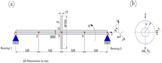
Figure 1.
Elastic rotor-bearing schematic: (a) Rotor-bearing schematic diagram showing its elements and nodes and (b) x–y coordinates.
The vector of nodular displacements is
Rotating Shaft Equation of Motion
The potential and kinetic energies of each element can be expressed in matrix form in terms of their nodal variables. Using Hamilton’s Principle [31], the finite element formulation for a rotating shaft can be derived. According to Hamilton’s Principle, the equation of motion is given by:
where , and represent the variations in kinetic energy, potential energy, and virtual work, respectively. The general equation of motion (EOM) for the system can be obtained by integrating Equation (1). This has been established in previous studies, such as those by Sayed, El-Sayed [32], Yu [33], and Laha [34].
where [] corresponds to the shaft’s total mass matrix, [] denotes the gyroscopic matrix, specifies the rotational speed, identifies the damping matrix, and [] represents the stiffness matrix. represents the vector of nodular displacements. The shaft is modeled by dividing it into small elements. Each element was assigned an 88 matrix for mass, gyroscopic, damping, and stiffness. These individual matrices were then combined to create the global system matrices. The details of the element mass, gyroscopic, and stiffness matrices are provided in Appendix A. The vector represents the external forces at any degree of freedom. This force vector consists of gravitational loads, unbalanced forces, and forces exerted by fluid film bearings , in the and directions at the start and end nodes of the shaft elements. Utilizing the variable-order method (ode15s) [35] within a MATLAB program (R2023b) allows us to obtain the system’s responses.
Figure 2 illustrates the sequence of steps followed to solve the equations of motion for the dynamic model. The solution of system and bearing parametric equations by high order polynomials is detailed in Appendix B. Figure 2 presents distinct polynomial fit equations for the second-order bearing coefficients as functions of eccentricity and Sommerfeld number. Polynomial functions of increasing order, up to the fourteenth degree, were generated. The fourteenth-order polynomial was determined to exhibit the highest accuracy. This equation enables the simple integration of bearing coefficients into the analysis of system dynamics across the complete Sommerfeld number spectrum.
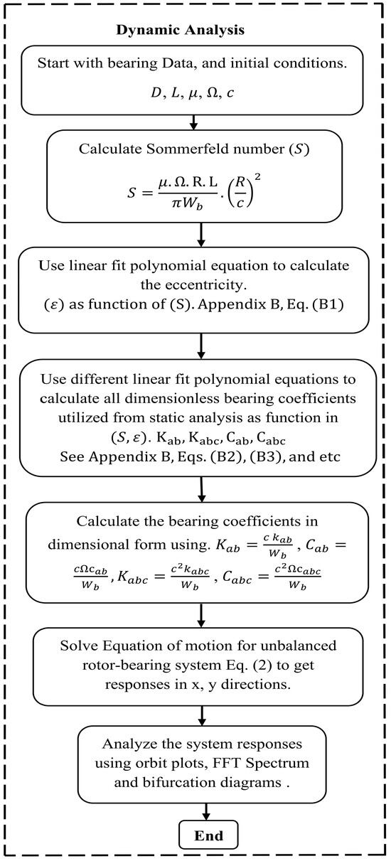
Figure 2.
Step-by-step diagram depicting the system dynamic procedure investigated to obtain theoretical findings.
3. Test Bench Explanation and Experimental Setup
Figure 3 and Figure 4 show pictures of the test bench used in the experiments. The rotating shaft and journal bearings, along with their detailed geometric and physical parameters, are outlined in Table 1. The test bench consists of two similar fluid film bearings with a length-to-diameter ratio of (2.5) to support the rotating steel shaft. The fluid parameters used in this work are displayed in Table 2. Figure 4 illustrates the supply of pressurized fluid to the fluid-lubricated journal bearing through a pressurized pump. Furthermore, the rotating disc is meticulously aligned such that it sits precisely at the midpoint of the axis. Adjustable speed drive controls a three-phase motor, enabling adjustment of the shaft’s rotation speed between 10 and 6000 rpm.
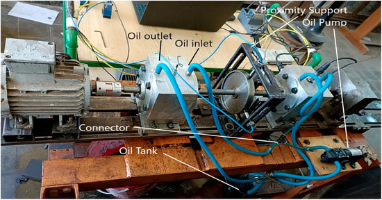
Figure 3.
Photograph showing the test bench components utilized to conduct tests on the system, which is based on two lubricated bearings.
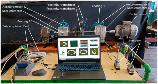
Figure 4.
A rear-aspect photograph revealing intricate details and functionalities within the machine.

Table 1.
Characteristics of the rotor-bearing dynamic system.

Table 2.
The parameters for the fluid film used in this work.
In order to track and record the shaft’s motion in the x and y directions, this study employs two displacement proximity transducers of the FK-452F model [37]. For secure positioning, the displacement transducers are fixed on a steel chassis, oriented perpendicularly to each other. As eddy current transducers approach a conductive object, the transducer probe’s magnetic field induces eddy currents within the object material. In response, the induced eddy currents create a magnetic field that counteracts the original field generated by the coil. This opposing magnetic field alters the coil’s impedance, allowing the recorded signals to be converted into displacement measurements. The transducer probe signals are acquired and processed using a National Instruments card 6216 with USB [38]. The transducer probes meet the IEC 61508 and/or IEC 61511 functional safety standards [39]. All accelerometers and NI Cards were tested and calibrated by National Instruments Corporations. The inverter and electric panel protected against overload and water droplets (IP01).
4. Theoretical Results of the Balanced Rotor-Bearing System
In this section, theoretical analysis is presented using a linear finite element model with Euler–Bernoulli beam elements to study the instability behavior of a rotor supported by two identical journal bearings. This theoretical analysis uses orbit plots and system responses to study the effect of varying rotational speeds on the rotor-bearing system. To investigate the threshold speed in this study, a first-order bearing force analysis was employed for both water and oil lubricants. System behavior was recorded as the speed increased. The threshold speed was observed and evaluated at the moment the system began to diverge.
4.1. Effect of Rotational Speed on Equilibrium Position
This section studies the effect of rotational speed on equilibrium position. Figure 5 shows the variation of eccentricity and attitude angles with shaft rotational speed when using oil and water as lubricants. It shows that the eccentricity of water as a lubricating fluid is large at low speeds, and the shaft’s stable point reaches the clearance circle. Figure 5 and Figure 6 illustrate that the eccentricity ratio decreased rapidly with increasing rotational speed in oil-lubricated bearings compared to water-lubricated bearings. In addition, the equilibrium point is influenced by both the rotational speed and the fluid’s viscosity. This necessitates the use of water as a lubricating fluid at high speeds, where the Sommerfeld number is too low, and high velocity compensates for this issue. Conversely, oil is examined as a lubricating fluid at both high and low speeds because its Sommerfeld number is within a suitable range. Therefore, to avoid rotor–stator contact, it is recommended to run water-lubricated bearings at higher rotational speeds than oil-lubricated bearings. In contrast, oil as a lubricating fluid has a suitable eccentricity value and shaft stable point at low speeds. Therefore, it is preferable to use water as a lubricating fluid at high speeds.
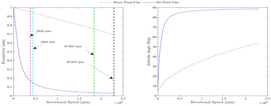
Figure 5.
Variation of eccentricity and attitude angle with rotational speed for two different lubricating fluids.
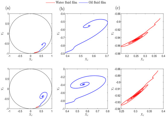
Figure 6.
Comparison of orbit behavior at two operating speeds below the threshold speed using water and oil as the lubricant fluid. The top row is for 3820 rpm, and the bottom row is for 4393 rpm. (a) Water and oil orbits with clearance circle, (b) oil orbit, and (c) water orbit.
Figure 6 explores the study of two cases from Figure 5, each below the theoretical threshold speed for both water and oil as fluid films. The orbit plot of water lubrication confirms that the shaft center reaches a stable point close to the bearing clearance circle.
This behavior is attributed to the combined effect of increasing eccentricity, as illustrated in Figure 5, and the consequently decreasing Sommerfeld number. For this reason, it is preferable to design water-lubricated bearings for use at high rotor rotational speeds. At these speeds, the fluid film bearings generate sufficient pressure within the bearing clearance, due to the fluid’s viscosity and the relative rotational speed between the rotor and bearing. As the rotor’s speed increases, the generated pressure gradually rises, eventually becoming adequate to fully support the rotor’s load, thereby preventing contact or friction between the rotor and stator in the rotor-bearing system. Finally, the main conclusion is that when using water as a lubricant, it should operate at higher speeds to stabilize far away from the clearance circle and to avoid rotor–stator contact.
4.2. Orbit and Time Response Plots
The present study employs two distinct theoretical approaches to examine the behavior of the rotor. The first investigation implements a second-order analysis to obtain the bearing forces, which are indicated in black. In the second analysis, highlighted in red, the bearing forces are calculated by completely employing a full numerical solution of the Reynolds equation at every time step. The cases studied using water as a lubricant fluid are listed in Table 3.

Table 3.
Examined cases for time responses and rotor-bearing orbits using water as a fluid film for bearing.
Figure 7 demonstrates the theoretical cases of high rotational speeds of 14,324 rpm, 18,382 rpm, and 22,918 rpm when using water as the lubricant fluid. The first-row panels a and b depict a stable orbit and its associated time response for the second-order and non-linear analyses, conducted at a speed of 14,324 rpm below the threshold speed. In panels c and d of the second row, non-linear analysis indicate an increasing trend in the response, but the second-order analysis shows a steady state limit cycle, with a speed close to the threshold speed. Lastly, in the third row, panels e and f show the speed of the axis above the threshold speed, the second-order analysis exhibits a steady-state limit cycle, and the non-linear analysis shows that the circle hits the clearance circle. These results demonstrate the limitations of the second-order analysis in evaluating the stability of the system. However, the application of more advanced continuation analysis techniques enables the determination of the type of limit cycle, whether subcritical or supercritical, in the system.
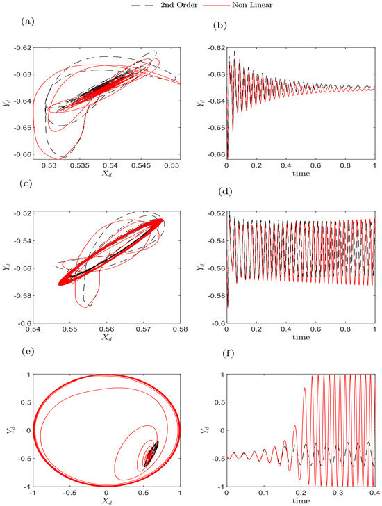
Figure 7.
Plots of the bearings’ centers and response on the -axis at several operating speeds, using water as the lubricant fluid. (a,b) 14,324 rpm, (c,d) 18,382 rpm, and (e,f) 22,918 rpm, as shown in Table 3.
Figure 8 presents the rotor orbits obtained using oil as the lubricant fluid with the operating conditions specified in Table 4. Figure 8a,b shows the orbit plot and response results for analyses conducted at speeds below the threshold, specifically at 3820 rpm. These analyses show that below the threshold speed, the system settles into a stable locus, with responses gradually diminishing over time. Figure 8c,d demonstrates the case at the threshold speed. For non-linear analysis, the journal center progressively increases until it reaches a stable limit cycle. Conversely, the second-order analysis orbit expands continuously until it becomes steady at a smaller limit cycle. As observed in Figure 8d, the non-linear analysis’s vibration amplitude was larger than that of the second-order analysis. Figure 8e,f shows the speed exceeding the threshold speed. In this analysis, the rotor’s behavior showed signs of instability. In the non-linear analysis, the response increased until the journal reached the bearing clearance circle. In contrast, in the second-order analysis, the orbit passed outside the clearance circle after entering the unstable zone. As observed in Figure 8f, the displacement in the vertical direction increased rapidly in this case. The orbit plot results indicate that the second-order bearing coefficients match the bearing response using the direct solution of the Reynolds equation below the threshold speed but diverges from the full Reynolds equation results above the threshold speed.
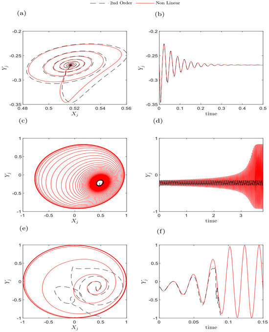
Figure 8.
Plots of the bearings’ centers and response on the -axis at various operating speeds, using oil as the lubricant fluid. (a,b) 3820 rpm, (c,d) 4393 rpm, and (e,f) 5730 rpm, as can be seen in Table 4.

Table 4.
Examined cases for time responses and rotor-bearing orbits using oil as a fluid film for bearing.
5. Experimental and Theoretical Results of an Unbalanced Rotor-Bearing System
This section presents a comparative analysis between the experimental observations obtained through experimentation on a test bench and the theoretical findings generated using a linear beam element model. This analysis compares the results when the unbalanced masses are 7.02 × 10⁻⁴ kg·m to 8.6 × 10⁻⁴ kg·m. Orbital radii were plotted for all cases using water and oil as lubricants at three rotational speeds: 4000, 5000, and 6000 rpm.
The analyses and studies account for unbalanced masses attached to uniformly distributed threaded holes along the circumference of the disc. The disc features three concentric circular arrays of threaded holes positioned at different radial distances, with an angular spacing of 15 degrees between adjacent holes. Each hole, with a diameter of 5 mm, is designed to hold small masses, allowing for the precise introduction of controlled unbalance. This configuration facilitates systematic variation of the imbalance to evaluate its influence on the dynamic response of the rotor-bearing system. The rotating disc positions in both vertical and horizontal displacements are denoted as and , respectively.
The specific components employed in the test bench setup are shown in Figure 3. The system’s dynamic response is analyzed across multiple cases at varying rotational speeds. These speeds were chosen to match those of the motor during experimental signal acquisition, with either water or oil serving as the working fluid. The bearing characteristics, fluid properties, and rotating disc specifications are summarized in Table 1.
This study examines the effect of unbalanced mass on the rotor-bearing system’s behavior and dynamic characteristics. The impact of unbalanced masses is highly noticeable in all rotor-bearing systems. Studying the effect of unbalanced masses helps us determine appropriate operating speeds for systems and avoid resonance conditions.
The experimental results for the unbalanced rotor are clearly visualized through color-coded plots, where each plot corresponds to a specific operating speed: magenta for 1000 rpm, green for 2000 rpm, cyan for 3000 rpm, red for 4000 rpm, blue for 5000 rpm, and black for 6000 rpm. A detailed breakdown of this analysis is provided in Table 5. In all cases, the second-order analysis can be found in the first column, the non-linear analysis is in the second column, the experimental orbit is displayed in the third column, and the last column presents the experimental FFT spectrum. By adhering to the derivatives techniques described by Ahmed, El-Sayed [26] (in Appendix C), the bearing coefficients were obtained based on second-order analysis. For non-linear analysis, the solution depends on the non-linear bearing forces. These forces are evaluated by solving the Reynolds equation at every time step. The practical results are presented with real measurements with a smooth filter to eliminate undesired noises.
5.1. Orbit and Responses Plots Utilizing Water as a Lubricant Fluid
Figure 9a–d and Figure 10a–d show the theoretical and practical orbits and FFT spectrum graphs for the system across a range of speeds. The analysis considered multiple system imbalance conditions, including unbalanced mass values of 7.02 10−4 kg·m and 8.6 10−4 kg·m. Utilizing water as a lubrication fluid provides a high threshold speed of 18,382 rpm (as drawn in Figure 7). Because of the limitations of the three-phase motor, practical measurements are restricted to a specific range of speeds. Figure 9 displays orbit plots for the three analyses for an unbalanced mass value of 7.02 10−4 kg·m. In the first row at 4000 rpm, the rotor orbit exhibits significant variations in both shape and radius in the second-order and non-linear analyses, but the second-order investigation closely resembles the patterns noticed in the non-linear investigation shown in the second column.


Table 5.
Experimental and theoretical studies investigated water as a lubricant. The system analyzed plots and behavior for two specific unbalanced mass values: 7.02 10−4 kg·m and 8.6 10−4 kg·m.
Table 5.
Experimental and theoretical studies investigated water as a lubricant. The system analyzed plots and behavior for two specific unbalanced mass values: 7.02 10−4 kg·m and 8.6 10−4 kg·m.
| System Configurations |
System Speed (rpm) |
Sommerfeld No. (S) |
Eccentricity Ratio (ε) |
|---|---|---|---|
| Figure 10 and Figure 11 (1st row) | 4000 | 0.00074 | 0.945 |
| Figure 10 and Figure 11 (2nd row) | 5000 | 0.00088 | 0.933 |
| Figure 10 and Figure 11 (3rd row) | 6000 | 0.01061 | 0.9216 |
The third row of Figure 9 depicts that the non-linear analysis yields an orbital shape and radius closer to the experimental findings compared to the second-order analysis. However, the second-order analysis reveals orbital growth, reaching a radius of 1.01 mm. Figure 9d and Figure 10d showcase the emergence of synchronous vibrations at higher speeds above 4000 rpm. Figure 10 illustrates the experimental and theoretical findings for an unbalanced mass value of 8.6 10−4 kg·m. Figure 10a presents the results of the second-order analysis, where the orbital radii values are 0.59 mm, 2.14 mm, and 1.24 mm. Figure 10b displays the results of the non-linear analysis, with orbital radii of 1.13 mm, 2.01 mm, and 0.69 mm. In Figure 10c the initial orbit radius is 0.38 mm, and it exhibits a consistent increase, reaching 0.58 mm at 5000 rpm and 0.61 mm at 6000 rpm. All three cases exhibit a clear trend: the orbit radius increases steadily until reaching an operating speed of 5000 rpm, after which it starts to decrease. This decrease is likely due to the system encountering a critical speed close to 5000 rpm. Despite this, the theoretical and practical results obtained with water as the lubricant fluid remain stable below this critical speed.
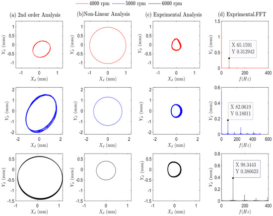
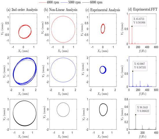
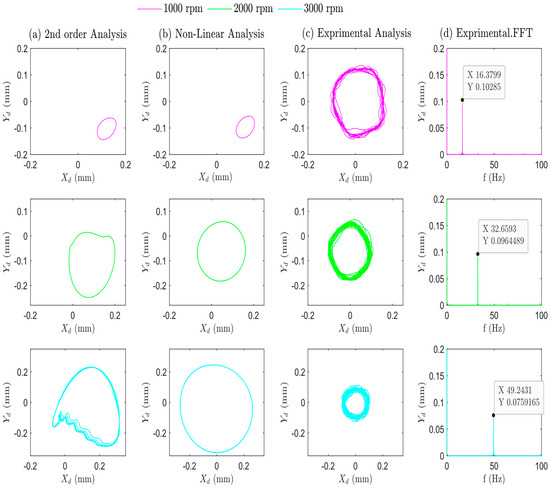

Figure 9.
Theoretical and practical results for the system using water as the lubricant fluid at different speeds from 4000 to 6000 rpm, with an unbalanced mass of 7.02 10−4 kg·m. The Figure analyzes the system’s response in terms of orbit plots at the bearing position. Column (a)—theoretical 2nd-order analysis. Column (b)—Non-Linear analysis. Column (c) shows the orbit plot after applying a smooth filter. Column (d) presents the frequency-domain analysis using the Fast Fourier Transform (FFT) to pick out the dominant frequencies present in the vibration.

Figure 10.
Theoretical and practical results for the system using water as the lubricant fluid at different speeds from 4000 to 6000 rpm, with an unbalanced mass of 8.6 10−4 kg·m. The Figure analyzes the system’s response in terms of orbit plots at the bearing position. Column (a)—theoretical 2nd-order analysis. Column (b)—Non-Linear analysis. Column (c) shows the orbit plot after applying a smooth filter. Column (d) presents the frequency-domain analysis using the Fast Fourier Transform (FFT) to pick out the dominant frequencies present in the vibration.

Figure 11.
Theoretical and practical results for the system using oil as the lubricant fluid at different speeds from 1000 to 3000 rpm, with an unbalanced mass of 7.02 10−4 kg·m. The Figure analyzes the system’s response in terms of orbit plots at the bearing position. Panel (a)—theoretical 2nd-order analysis. Panel (b)—Non-Linear analysis. Panel (c) shows the orbit plot after applying a smooth filter. Panel (d) presents the frequency-domain analysis using the Fast Fourier Transform (FFT) to pick out the dominant frequencies present in the vibration.
5.2. Orbit and Response Plots Utilizing Oil as a Lubricant Fluid
Figure 11 and Figure 12 present the theoretical and practical orbits and FFT spectrum graphs for the system at various speeds as depicted in Table 6. These figures include subplots (a), (b), (c), and (d) for each case, possibly illustrating different aspects of the system’s behavior under various operating speeds, using a system unbalanced mass of 7.02 × 10⁻⁴ kg. Figure 11 showcases steady-state orbits for second-order and non-linear analyses in panels (a) and (b). It is noteworthy that for speeds below the critical speed, a stable orbit is observed with increasing radii: 0.09 mm at 1000 rpm (first row), 0.189 mm at 2000 rpm (second row), and 0.282 mm at 3000 rpm (third row). Column (c) presents consistent findings across the three speed ranges with 0.12 mm orbital radii. The Fast Fourier Transform (FFT) spectra in column (d) reveal pure rotational frequency peaks for the analyzed cases within speeds below the threshold speeds.
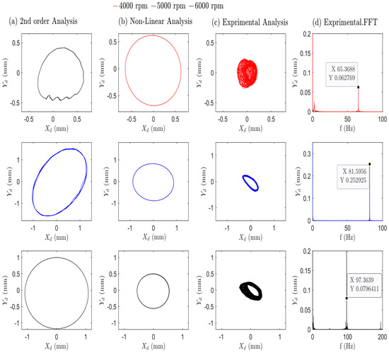
Figure 12.
Theoretical and practical results for the system using oil as the lubricant fluid at different speeds (from 4000 to 6000 rpm), with an unbalanced mass of 7.02 10−4 kg·m. The Figure analyzes the system’s response in terms of orbit plots at the bearing position. Panel (a)—theoretical 2nd-order analysis. Panel (b)—Non-Linear analysis. Panel (c) shows the orbit plot applying a smooth filter. Panel (d) presents the frequency-domain analysis using the Fast Fourier Transform (FFT) to pick out the dominant frequencies present in the vibration.

Table 6.
Overview of the experimental and theoretical cases examined with oil as the lubricant. The system’s response and behavior are analyzed for two specific unbalanced mass values: 7.02 × 10⁻⁴ kg·m and 8.6 × 10⁻⁴ kg·m.
Figure 12 clearly depicts the substantial changes in both orbit radii and shape as the shaft speed gradually increases across the three analyses presented in panels (a), (b), and (c). In panel (c), the experimental orbit in the first and third rows clearly exhibits a chaotic-like response, characterized by numerous impacts potentially caused by the system passing through critical speeds. The second row of Figure 12 compares the results from second-order, non-linear, and experimental analyses at a speed of 5000 rpm. All analyses exhibit growth of the orbital radii and FFT spectrum compared to lower-speed cases. Each analysis indicates that the second-order analysis reveals a peak orbit radius of 1.54 mm and the non-linear analysis records 0.85 mm, respectively. The increase in the orbit radius and amplitude of vibration at 5000 rpm led to a high amplitude of vibration caused by the rotational speed approaching the resonance speed.
Panels (b) and (c) in Figure 12 show noticeable differences in the orbit shape and radii between the non-linear analysis and practical analysis. It appears clearly in all panels (a, b, and c) of Figure 11 and Figure 12. The third row of Figure 12 reveals that both the second-order and non-linear analyses predict significantly lower orbit radii for a speed of 6000 rpm compared to the results obtained at 5000 rpm. Some key factors contribute to this behavior. The first is the rotor’s natural frequencies coinciding with the operating speed range. This phenomenon, known as resonance, can significantly amplify the system’s response when operating near these critical speeds. Beyond the resonant region (where the response is amplified), the vibration response generally decreases as speed increases further.
The second factor, the system’s stiffness and damping properties, also influences the response. At lower speeds, the system might exhibit lower stiffness and damping, leading to amplified responses. Conversely, as the speed increases, the effects of stiffness and damping become more pronounced, resulting in a decrease in the response [40]. To clearly study these cases and determine the system’s natural frequencies, the equations were numerically solved. The first natural frequency was recorded as 85.12 Hz, as shown in Table 7.

Table 7.
The first four theoretical lateral natural frequencies of the investigated rotor-bearing system.
Figure 13 focuses on the operating speeds below the critical speed. Here, both theoretical and practical findings are presented for orbit trajectories and the FFT spectrum. These results are for an increased unbalanced mass equal to 8.6 × 10⁻⁴ kg·m. To discuss the influence of the unbalanced mass on the system, small masses were added to the disc through threaded holes with a diameter of 5 mm distributed around the perimeter of the disc. This process increased the overall unbalanced mass of the rotor. The first row of Figure 13 presents a significant distinction in the orbital radius and orbit profile at a speed of 1000 rpm. At a speed of 2000 rpm, as shown in the second row, the orbit radius exhibits minimal change, with values of 0.13 mm, 0.12 mm, and 0.134 mm for the second-order, non-linear, and experimental analyses, respectively. The third row demonstrates consistent orbit behavior across second-order and non-linear analyses, and the orbit radius remains around 0.28 mm for the first two analyses (columns a and b), which does not align with the practical orbit in the third column.
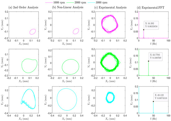
Figure 13.
Theoretical and practical results for the system using oil as the lubricant fluid at different speeds (from 1000 to 3000 rpm), with an unbalanced mass of 8.6 10−4 kg·m. The Figure analyzes the system’s response in terms of orbit plots at the bearing position. Panel (a)—theoretical 2nd-order analysis. Panel (b)—Non-Linear analysis. Panel (c) shows the orbit plot applying a smooth filter. Panel (d) illustrates the frequency-domain analysis using the Fast Fourier Transform (FFT) to pick out the dominant frequencies present in the vibration.
Figure 14 illustrates the system’s behavior near and above the critical speed, revealing important details about the system’s response. At a speed of 4000 rpm, all analysis methods predict an increase in orbit radii. The second-order analysis shows a slightly higher value of 0.51 mm, the non-linear analysis yields the largest predicted radius, reaching 0.85 mm, and the experimental orbit showed a radius of 0.28 mm. By further increasing the rotational speed beyond the values shown in the second row of Figure 14, the system ultimately exceeds the first critical speed. It is listed as 5107 rpm, as configured in Table 7. Consequently, all panels within the third row of Figure 14 illustrate a significant decrease in the observed values once the system surpasses the resonant speed.
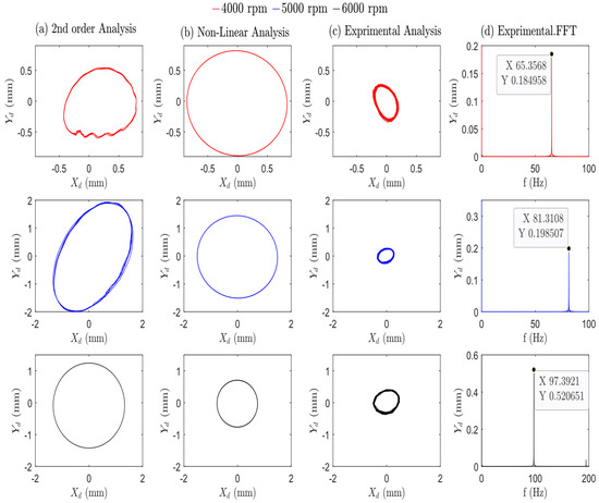
Figure 14.
Theoretical and practical results for the system using oil as the lubricant fluid at different speeds (from 4000 to 6000 rpm), with an unbalanced mass of 8.6 10−4 kg·m. The Figure analyzes the system’s response in terms of orbit plots at the bearing position. Panel (a)—theoretical 2nd-order analysis. Panel (b)—Non-Linear analysis. Panel (c) shows the orbit plot applying a smooth filter. Panel (d) displays the frequency-domain analysis using the Fast Fourier Transform (FFT) to pick out the dominant frequencies present in the vibration.
Figure 14 depicts, across all panels, the system’s behavior as the speed increases from 4000 rpm to 6000 rpm. The orbit plots describe a gradual expansion, with the radius increasing until the resonant speed of the system is reached, followed by a decrease in the orbit radius after surpassing the resonant speed. The practical and theoretical results generally have an acceptable match for orbit shapes across all studied examples. A thorough analysis reveals that the non-linear analysis provides the closest agreement to the practical results.
5.3. Overview of Theoretical vs. Experimental Findings: Oil vs. Water Lubricants
In this section, the key results from Section 5.1 and Section 5.2 are summarized in Table 8 to enable a clear comparison of the three analyses. Using the generated orbit plots, the Table was created based on orbit radius to analyze the second-order, non-linear, and experimental results. The orbit radius is evaluated by the radius of the nearest circle that can fit the orbit shape and it approximately represents the amplitude of vibration displacement.

Table 8.
Comparison between theoretical and experimental orbit radii for two unbalanced masses.
Additionally, Table 8 provides a comparative analysis of oil and water lubricants at similar operating speeds, ensuring a meaningful comparison. The analysis also includes two distinct unbalanced masses: 7.02 × 10−⁴ kg·m and 8.6 × 10−⁴ kg·m, respectively. The results show that, in most cases, the response amplitude is higher when using water as a lubricant compared to oil. This difference can be attributed to the fluid’s viscosity, which plays a crucial role in the dynamic performance of the journal bearing, leading to greater vibration amplitudes with water lubrication.
6. Conclusions
This study presents a comprehensive comparative analysis of water- and oil-lubricated bearings in rotor-bearing systems, using both theoretical and experimental approaches. This research offers valuable insights into the dynamic behavior of these systems under various operating conditions. To analyze the rotor’s behavior and its vibration characteristics, this study employed multiple techniques, including rotor orbit plots, vibration amplitude (response) measurements, and FFT spectra.
Key findings include:
Influence of Rotational Speed: The rotational speed was found to have a significant impact on the system’s dynamics, affecting the equilibrium position, eccentricity ratio, and overall stability.
Theoretical analysis method: Orbit plot analysis revealed that second-order bearing coefficients align well with the bearing response derived from the direct solution of the Reynolds equation below the threshold speed. However, discrepancies arise when compared to the full Reynolds equation results above the threshold speed.
Threshold Speed: Water-lubricated bearings were shown to have a threshold speed nearly four times higher than that of oil-lubricated bearings under the same operating parameters and conditions.
System Stability: In all studied cases, whether using water or oil as the lubricant, the rotor-bearing system remained stable up to the threshold speed. Beyond this threshold, system stability varied depending on specific operating conditions. For water-lubricated bearings, operating below the threshold speed resulted in a low Sommerfeld number and increased eccentricity, causing the shaft center to rotate behind the bearing clearance circle. Such conditions are not recommended, as they can increase the risk of rotor-stator rubbing, potentially leading to further system damage.
Validation Through Experimental Testing: The experimental tests carried out in this study offered critical insights, confirming the accuracy of the theoretical predictions and enhancing the overall understanding of rotor-bearing system dynamics.
Design Implications for Water Lubrication: The findings suggest that water-lubricated bearings are well-suited for high-speed applications. Furthermore, the analysis highlights the critical role of fluid viscosity in determining the system’s operational speed, as demonstrated through both experimental and theoretical trajectory plots, as well as FFT spectra.
For future research on rotor-bearing systems, the author suggests:
Investigating the experimental behavior and dynamic characteristics of high-speed rotor-bearing systems at speeds exceeding 10,000 rpm.
Conducting experimental studies on the effects of radial loads applied to the rotor shaft.
Exploring intelligent fault diagnosis for rotor-bearing systems under varying operating conditions.
Author Contributions
O.A. prepared the first draft. H.S. supervised the research and share in coding. T.A.E.-S. supervised the research. All authors have read and agreed to the published version of the manuscript.
Funding
This research received no external funding.
Data Availability Statement
Datasets are available from the corresponding author upon request.
Conflicts of Interest
The authors declare no conflicts of interest.
Nomenclature
| Bearing internal clearance. | |
| Bearing damping coefficients in dimensionless form (-) cartesian coordinates: where, a, b, c = , . | |
| Forces generated by the fluid film bearings (N). | |
| [] | Gyroscopic matrix. |
| Thickness of the lubricant (m). | |
| The thickness of the lubricant is in dimensionless form . | |
| [ | Element stiffness matrix. |
| Bearing stiffness coefficients is in dimensionless form (-) cartesian coordinates: a, b, c = , . | |
| Bearing total length (m). | |
| Element mass matrix. | |
| Fluid film pressure (N/m2). | |
| Pressure of the lubricant is in dimensionless form . | |
| Steady-state pressure is in dimensionless form. | |
| , | Gradient pressure cartesian coordinates. |
| , | |
| Bearing radius (m). | |
| Bearing total weight (N). | |
| , , | Displacement, velocity, and acceleration in dimensionless form. |
| Transverse motion for rotor and journal. | |
| Axial coordinate of the axis. | |
| Axial coordinate of the axis is in dimensionless form . | |
| Shaft speed (rpm). | |
| Bending deformation of the rotations. | |
| Fluid density (kg/m3). | |
| Fluid viscosity (N·s/m2). | |
| Eccentricity ratio . |
Appendix A. FE Matrices
This appendix details the parameters of the studied system in matrix form. The matrices represent the system’s mass, gyroscopic, and stiffness.
The following equation shows the distinct form of the mass matrix:
This is the form that exhibits the gyroscopic matrix:
Lastly, the stiffness matrix, which characterizes the elastic properties of the system, is able to be stated as:
Appendix B. Equations for System and Bearing Parameters Using Higher-Order Polynomials
This formula expresses the fitting relationship between the eccentricity ratio and the Sommerfeld number, using them to find the bearing coefficients:
Appendix C. Studied Lubricated Bearings Attributes
The Reynolds equation is a key tool for analyzing lubricated bearings. Finding the solution of this equation, we can obtain the pressure distribution of the oil film within the bearing presented in Figure A1a–d:
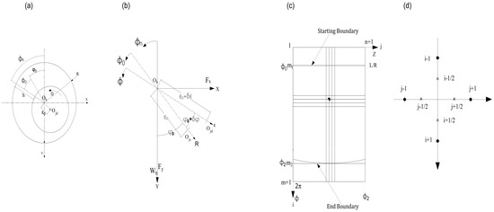
Figure A1.
Lubricated Bearing with a circular shape. (a) Coordinate system for the lubricated bearing. (b) Perturbed journal within the bearing, with angular () and (,) coordinates. (c) Oil film mesh for pressure distribution analysis. (d) Grid points used in the half-step FDM.
The following is an expression for the Reynolds equation in dimensionless form,
where,
represents the pressure distribution of the liquid film.
represents the film thickness.
represents the angular rotational position.
represents the axis speed.
represents the time.
represents the axis of rotation for shaft.
presently, c is the radial clearance, , and .
where, , and
When is small, =, and . Then,
where,
Using Equation (C6) and the transformation of Equation (C8), the expressions for the 1st order and the 2nd order of the perturbed liquid layer thickness in - coordinates can be estimated.
In this equation, the following symbols are used:
: Represents the steady-state pressure.
: Represent variables are specified as , respectively.
(′): prime symbol represents the derivative of a function with respect to τ.
: Represents a dimensionless parameter defined as τ = , where (t) is time and is the speed of the axis.
The dimensionless bearing forces and , might be evaluated using the following equations:
The following equation presents the definition of the dimensionless bearing forces in the and directions:
where, is the total bearing load, and as drawn in Figure 2.
and,
where, .
The eight-1st order bearing coefficients could be obtained by integrating the pressure distribution within the bearing,
the six 2nd-order stiffness and eight damping coefficients might be specified by,
where, each of .
References
- Elsayed, E.K.; Alaa, M.E.-B. A study on hydrodynamic water lubricated journal bearing. Eng. Res. J. 2017, 153, M1–M15. [Google Scholar]
- Xie, Z.; Jiao, J.; Yang, K.; Zhang, H. A state-of-art review on the water-lubricated bearing. Tribol. Int. 2023, 180, 108276. [Google Scholar] [CrossRef]
- Chen, C.; Li, S.; Lu, Z.; Ma, Z.; Li, G.; Zhang, Y. Experimental Study on Material Properties of Bearing Bush of Water Lubricated Bearing. IOP Conf. Ser. Mater. Sci. Eng. 2020, 740, 012067. [Google Scholar] [CrossRef]
- Chen, D.; Zhao, Y.; Sun, K.; Pan, R.; Fan, J. Analysis of the impact of graphene nano-lubricating oil on thermal performance of hydrostatic bearing. Ind. Lubr. Tribol. 2024, 76, 545–553. [Google Scholar] [CrossRef]
- Mousavi, S.B.; Zeinali Heris, S.; Estellé, P. Viscosity, tribological and physicochemical features of ZnO and MoS2 diesel oil-based nanofluids: An experimental study. Fuel 2021, 293, 120481. [Google Scholar] [CrossRef]
- Mousavi, S.B.; Pourpasha, H.; Heris, S.Z. High-temperature lubricity and physicochemical behaviors of synthesized Cu/TiO2/MnO2-doped GO nanocomposite in high-viscosity index synthetic biodegradable PAO oil. Int. Commun. Heat Mass Transf. 2024, 156, 107642. [Google Scholar] [CrossRef]
- Mousavi, S.B.; Zeinali Heris, S. Experimental investigation of ZnO nanoparticles effects on thermophysical and tribological properties of diesel oil. Int. J. Hydrogen Energy 2020, 45, 23603–23614. [Google Scholar] [CrossRef]
- Zhang, X.L.; Yin, Z.W.; Jiang, D.; Gao, G.Y. Comparison of the lubrication performances of water-lubricated and oil-lubricated plain journal bearings. Appl. Mech. Mater. 2015, 711, 27–30. [Google Scholar] [CrossRef]
- Soni, S.; Vakharia, D. Performance analysis of short journal bearing under thin film lubrication. Int. Sch. Res. Not. 2014, 2014, 281021. [Google Scholar] [CrossRef][Green Version]
- Xiang, G.; Wang, J.; Zhou, C.; Shi, Y.; Wang, Y.; Cai, J.; Wang, C.; Jin, D.; Han, Y. A tribo-dynamic model of coupled journal-thrust water-lubricated bearings under propeller disturbance. Tribol. Int. 2021, 160, 107008. [Google Scholar] [CrossRef]
- Zhang, X.; Yu, T.; Ji, H.; Guo, F.; Duan, W.; Liang, P.; Ma, L. Analysis of Water-Lubricated Journal Bearings Assisted by a Small Quantity of Secondary Lubricating Medium with Navier–Stokes Equation and VOF Model. Lubricants 2024, 12, 16. [Google Scholar] [CrossRef]
- Xu, B.; Guo, H.; Wu, X.; He, Y.; Wang, X.; Bai, J. Static and dynamic characteristics and stability analysis of high-speed water-lubricated hydrodynamic journal bearings. Proc. Inst. Mech. Eng. Part J J. Eng. Tribol. 2022, 236, 701–720. [Google Scholar] [CrossRef]
- Chen, S.; Xiang, G.; Fillon, M.; Guo, J.; Wang, J.; Cai, J. On the tribo-dynamic behaviors during start-up of water lubricated bearing considering imperfect journal. Tribol. Int. 2022, 174, 107685. [Google Scholar] [CrossRef]
- Zhu, H.M.; Chen, W.F.; Zhu, R.P.; Zhang, L.; Gao, J.; Liao, M.J. Dynamic analysis of a flexible rotor supported by ball bearings with damping rings based on FEM and lumped mass theory. J. Cent. South Univ. 2020, 27, 3684–3701. [Google Scholar] [CrossRef]
- Mallya, R.; Shenoy, B.S.; Pai, B.R. Experimental Challenges and Solutions in Design and Operation of the Test Rig for Water Lubricated Journal Bearing. Int. J. Energy Power Eng. 2014, 8, 1825–1828. [Google Scholar]
- Geng, T.; Meng, Q.; Wang, N.; Yuan, X.; Meng, Q.; Jia, Q. Experimental investigation of film pressure distribution in water-lubricated rubber journal bearings. Proc. Inst. Mech. Eng. Part. J J. Eng. Tribol. 2014, 228, 397–406. [Google Scholar] [CrossRef]
- Qian, B.; Ran, Y.; Ding, Q.; Sun, W.; Ma, C. Experiment and Simulation Analysis of the Vibration Response of the Rotor-Bearing System; Internet Archive Scholar: San Francisco, CA, USA, 2023. [Google Scholar]
- Wang, Y.; Yin, Z.; Jiang, D.; Gao, G.; Zhang, X. Study of the lubrication performance of water-lubricated journal bearings with CFD and FSI method. Ind. Lubr. Tribol. 2016, 68, 341–348. [Google Scholar] [CrossRef]
- Simmons, G.F. Journal Bearing Design, Lubrication and Operation for Enhanced Performance; Luleå Tekniska Universitet: Luleå, Sweden, 2013. [Google Scholar]
- Hariharan, G.; Kumar, S.; Kumar, N. Enhancing performance in water lubricated bearings with groove structures: A CFD analysis. Cogent Eng. 2024, 11, 2399762. [Google Scholar] [CrossRef]
- El-Sayed, T.; Sayed, H. Bifurcation analysis of rotor/bearing system using third-order journal bearing stiffness and damping coefficients. Nonlinear Dyn. 2022, 107, 123–151. [Google Scholar] [CrossRef]
- Lin, C.-L.; Liang, J.-W.; Huang, Y.-M.; Huang, S.-C. A novel model-based unbalance monitoring and prognostics for rotor-bearing systems. Adv. Mech. Eng. 2023, 15, 16878132221148019. [Google Scholar] [CrossRef]
- Yin, T.; Zhang, G.; Du, J.; To, S. Nonlinear analysis of stability and rotational accuracy of an unbalanced rotor supported by aerostatic journal bearings. IEEE Access 2021, 9, 61887–61900. [Google Scholar] [CrossRef]
- Yadav, H.; Upadhyay, S.H.; Harsha, S.P. Study of effect of unbalanced forces for high speed rotor. Procedia Eng. 2013, 64, 593–602. [Google Scholar] [CrossRef]
- Sayed, H.; El-Sayed, T. Nonlinear dynamics and bifurcation analysis of journal bearings based on second order stiffness and damping coefficients. Int. J. Non-Linear Mech. 2022, 142, 103972. [Google Scholar] [CrossRef]
- Ahmed, O.; El-Sayed, T.; Sayed, H. Finite element analyses of rotor/bearing system using second-order journal bearings stiffness and damping coefficients. J. Vib. Control 2023. [Google Scholar] [CrossRef]
- El-Sayed, T.; Friswell, M.I.; Sayed, H. Approximating fluid bearing characteristics using polynomials for the nonlinear dynamics of rotating machines. Tribol. Int. 2023, 187, 108669. [Google Scholar] [CrossRef]
- Sayed, H.; El-Sayed, T.A.; Friswell, M. Continuation Analysis of Rotor Bearing Systems Through Direct Solution of Reynolds Equation. In Advances in Machinery, Materials Science and Engineering Application IX; IOS Press: Amsterdam, The Netherlands, 2023; pp. 217–222. [Google Scholar]
- Miraskari, M.; Hemmati, F.; Gadala, M.S. Nonlinear dynamics of flexible rotors supported on journal bearings—Part II: Numerical bearing model. J. Tribol. 2018, 140, 021705. [Google Scholar] [CrossRef]
- Huang, S.; Chen, F.; Chen, Y. Research on the dynamic characteristics of hydrodynamic bearing subjected to base shock loads. Res. Sq. 2024; preprint. [Google Scholar] [CrossRef]
- Marion, J.B.; Thornton, S. Hamilton’s principle—Lagrangian and Hamiltonian dynamics. In Classical Dynamics of Particles and Systems; Elsevier: Amsterdam, The Netherlands, 1965; pp. 214–266. [Google Scholar]
- Sayed, H.; El-Sayed, T.A.; Friswell, M.I.; El-Mongy, H.H. Nonlinear dynamics analysis of hydraulic turbochargers in reverse osmosis desalination plants. Nonlinear Dyn. 2024, 112, 18817–18846. [Google Scholar] [CrossRef]
- Yu, J.J. Dynamic Analysis of Rotor-Bearing Systems Using Three-Dimensional Solid Finite Elements; University of Alberta: Edmonton, AB, Canada, 1998. [Google Scholar]
- Laha, S.K. Analysis of Stability and Unbalance Response of Flexible Rotor Supported on Hydrodynamic Porous Journal Bearing. Ph.D. Thesis, Indian Institute of Technology Guwahati, Guwahati, India, 2010. [Google Scholar]
- Strang, G. Computational Science and Engineering; SIAM: Philadelphia, PA, USA, 2007. [Google Scholar]
- ISO-VG32; Industrial Liquid Lubricants—ISO Viscosity Classification. International Organization for Standardization: Geneva, Switzerland, 1992.
- Shinkawa. Noncontact Displacement/Vibration Transducers (FK Series); Shinkawa Sensor Technology: Tokyo, Japan, 2024. [Google Scholar]
- National Instruments. DAQ M Series (NI USB-621x User Manual); National Instruments Corporate: Austin, TX, USA, 2009. [Google Scholar]
- Smith, D.J.; Simpson, K.G. The Safety Critical Systems Handbook: A Straightforward Guide to Functional Safety: IEC 61508 (2010 Edition), IEC 61511 (2015 Edition) and Related Guidance; Butterworth-Heinemann: Oxford, UK, 2020. [Google Scholar]
- Singiresu, S.R. Mechanical Vibrations; Addison Wesley: Boston, MA, USA, 1995. [Google Scholar]
Disclaimer/Publisher’s Note: The statements, opinions and data contained in all publications are solely those of the individual author(s) and contributor(s) and not of MDPI and/or the editor(s). MDPI and/or the editor(s) disclaim responsibility for any injury to people or property resulting from any ideas, methods, instructions or products referred to in the content. |
© 2024 by the authors. Licensee MDPI, Basel, Switzerland. This article is an open access article distributed under the terms and conditions of the Creative Commons Attribution (CC BY) license (https://creativecommons.org/licenses/by/4.0/).