Abstract
In ultra-precision machining (UPM), position-independent geometric errors (PIGEs), i.e., squareness errors, have a crucial impact upon the form accuracy of a machined surface. Accordingly, more research work has been conducted in PIGE identification, to improve the form accuracy. However, the general identification methods were developed without consideration of the specific squareness errors for crucial PIGEs under the form errors of the machining process. Therefore, a new method with featured structures was proposed, to identify crucial PIGEs in UPM. Firstly, a volumetric error model was developed for PIGEs, to discuss the relationship between squareness errors and their resulting machining form errors. Secondly, following the developed model, some featured structures have been proposed with their machining form errors, to significantly indicate crucial PIGEs. Finally, a series of UPM and measuring experiments were conducted for the featured structures, and then their machining form errors were measured and extracted with specific squareness errors for the identification of crucial PIGEs. The theoretical and experimental results revealed that the proposed method is simple and efficient with the featured structures to accurately identify crucial PIGEs in UPM. Significantly, the study offers a deep insight into high-quality fabrication in UPM.
1. Introduction
Ultra-precision machining (UPM) is one of the most advanced fabrication methods to create a high-quality surface with a sub-micrometric form accuracy and nanometric surface roughness []. In UPM, there are inevitably various errors that affect the surface quality of the machined components, such as geometric errors [,], tool errors [,], thermal errors [,], dynamic errors [,], etc. The geometric errors, as a crucial contributor of up to 40–70%, majorly affect the form accuracy of a machined surface []. Obviously, the identification of geometric errors is the key way improving form accuracy. According to ISO 230-1 and ISO 230-7 [,], geometric errors can be categorized into position-dependent geometric errors (PDGEs), and position-independent geometric errors (PIGEs), referred to as squareness errors []. Compared to PDGEs, PIGEs greatly contribute to the form errors in UPM [,,]. Therefore, more research work has been focused on PIGE identification in UPM.
Currently, the common identification methods under signal measurement and separation have been developed to calibrate PIGEs via optical square bricks, probes, double ball bars, etc. Lai et al. [] presented a squareness identification method for an ultra-precision motion stage via error separation, where an optical square brick was employed to measure the squareness accuracy between the X-axis and Y-axis. Moreover, Maeng et al. [] utilized a touch probe to identify four PIGEs in the rotary axis of a five-axis UPM machine. Liu et al. [] used a high-precision standard bar and a pair of inductance displacement probes to calibrate two PIGEs in the spindle of a drum roll UPM lathe. Chen et al. [] put forward an empirical mode detection method in which a reference ball and a touch probe with a ruby stylus were used to identify PIGEs in the rotary axis of a five-axis UPM machine. Further, Jiang et al. [] established a new testing procedure to identify and characterize the PIGEs of the rotary axes in a five-axis machine, through a four-step process with double ball bars. Song et al. [] carried out measurement experiments with double ball bars to extract seven PIGEs for the geometric errors of a five-axis UPM machine. It is, thus, clear that these proposed methods were carried out only to identify PIGEs, but the machining form errors would not be fully considered with crucial PIGEs under the machining process.
Moreover, the identification methods under trial cutting have been proposed to identify the crucial PIGEs from the form errors of a machined surface, which was employed to evaluate the actual accuracy of a machine. Gao et al. [] calculated coupling PIGEs through the measured surface of a machined workpiece. Pezeshki et al. [] designed a set of test pieces to distinguish kinematic errors coupled with PIGEs from machined profiles, and assessed the performance of a three-axis machine under real loading conditions. Liu et al. [] classified PIGEs according to the coordinate distortion directions, from which it was identified that their main errors would have a key impact on the form accuracy. Li et al. [] analyzed the effects of surface form distortion on the optical performance, to identify the main machining errors including PIGEs. Tao et al. [] proposed a matrix decomposition method to detect the equivalent geometric errors from a machined surface. Zha et al. [] presented an evaluation method to improve the machining accuracy of curved surfaces via measuring the profile error, to identify, and further compensate for, the machining error, which consists of the systematic error caused by PIGEs, and the random error due to uncertainty. Although the research work has made significant contributions to the identification methods under trial cutting, the error, identified from the machined surface, is only an equivalent error coupled with some PIGEs, but not a specific crucial PIGE. This would limit the methods being widely used in the machining process.
As mentioned above, the identification methods under trial cutting would accurately indicate squareness errors for PIGEs in UPM, but how to recognize each crucial PIGE from a machined surface necessitates a comprehensive discussion. Therefore, this study proposed a new method with featured structures to recognize the specific squareness errors for the crucial PIGEs in UPM. Firstly, a volumetric error model for PIGEs was established, to present the relationship between squareness errors and their resulting machining form errors. Secondly, some featured structures were designed, to allow us to identify the crucial PIGEs from the developed model. Finally, the machining form errors were accurately extracted for the crucial PIGEs, through a series of UPM and measurement experiments on the designed featured structures, in order to verify the new proposed method.
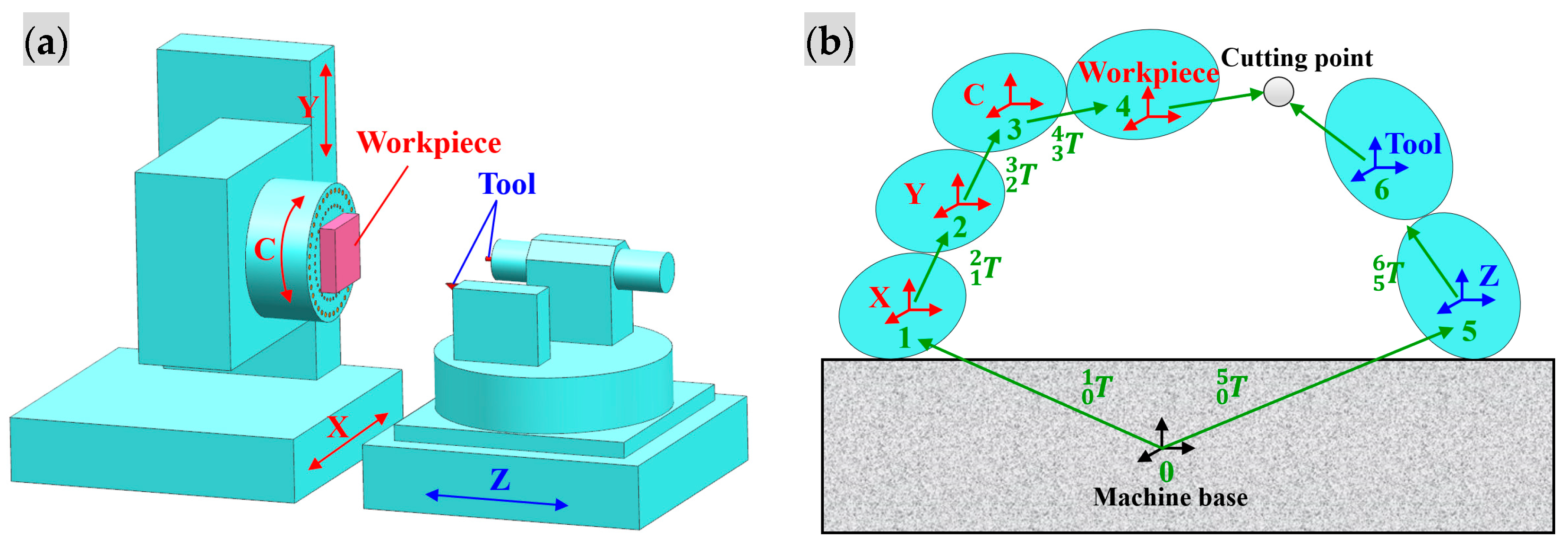
2. Volumetric Error Modelling for PIGEs
During the machining process, the actual machining trajectory would deviate from the ideal machining trajectory, due to the PIGEs generated via machine assembly errors. This would induce the machining form error, called the volumetric error. It is employed to describe the relationship between the PIGEs and their resulting machining form errors, based on the machine system. As shown in Figure 1a, the machine system used is a four-axis UPM machine, consisting of three linear axes (the X-axis, Y-axis, and Z-axis), and a rotary axis (the C-axis). The X- and Z- axes are located on the machine base, respectively. The Y-axis is mounted on the X-axis, and the C-axis moves with the Y-axis. The workpiece is attached to the C-axis via the vacuum chuck, and runs with the C-axis, which forms the workpiece motion chain with the Y-axis, the X-axis, and the C-axis (the red part in Figure 1). The tool is mounted on the cutter frame, moving with the Z-axis, which forms the tool motion chain with the Z-axis (the blue part in Figure 1).
Figure 1.
The system of the employed four-axis UPM machine: (a) its schematic diagram, (b) its motion chains.
Additionally, the PIGEs represent the squareness errors along each axis deviating from the ideal reference at constant values []. For the four-axis UPM machine, there are five squareness errors, the symbols and descriptions of which are listed in Table 1. According to the multi-body system theory [], the four-axis UPM machine is abstracted into an adjacent body array, following the workpiece and tool motion chains, and the correlation between each adjacent body is intuitively described via a low-order body sequence. As shown in Figure 1b, the low-order body sequence represents the order of the bodies in terms of natural numbers, and the machine base is usually defined with the 0 body as the reference. Accordingly, the workpiece and tool motion chains are numbered sequentially at the increasing sequences from the reference.
Table 1.
The symbols and descriptions of the PIGEs for the UPM machine.
Moreover, on the basis of the multi-body system, a 4 × 4 homogeneous transformation matrix is used to describe the actual motion position between two adjacent bodies. For the PIGEs, the homogeneous transformation matrix between a low-order body i and its adjacent high-order body j is expressed as
where and represent an error transformation matrix and a motion transformation matrix, respectively. The formulas for the transformation matrices and between two adjacent bodies are given in Table 2, where x, y, and z denote the moving distance of the X-, Y- and Z-axes, respectively; θc denotes the rotating angle of the C-axis; and I4×4 denotes a fourth-order identity matrix.
Table 2.
The error and motion position transformation matrices of the UPM machine.
Further, the coordinate systems are established for the workpiece position and tool position, respectively. is employed to express the tool position in the tool coordinate system. Correspondingly, the ideal tool motion position and the actual tool motion position in the workpiece coordinate system are expressed as:
Accordingly, the deviation in the tool motion position is the volumetric error induced by the PIGEs. It is denoted by the symbol E, and its corresponding error components in the X-, Y-, and Z-directions are expressed as Ex, Ey, and Ez, respectively. The volumetric error is written as:
For Equation (4), assuming that the squareness errors are first-order infinitesimals, whose corresponding sine is themselves and whose cosine is 1, and that the higher-order infinitesimals are 0, the volumetric error components in the X-, Y-, and Z-directions, respectively, are re-written as:
Finally, the volumetric error model for the PIGEs developed from above clearly describes the relationship between the squareness errors and their resulting machining form errors in UPM. It would provide a theoretical expression for the recognition of crucial PIGEs.
3. Recognition of the Crucial PIGEs with the Featured Structures
In Equations (5)–(7), each volumetric error is coupled with other squareness errors, and changes with the motion position along each axis, meaning that a specific squareness error cannot be directly calculated. Therefore, some featured structures could be designed in order to recognize the crucial PIGEs, which would amplify the contribution of the specific squareness error to the volumetric error, weaken the influence of other squareness errors, and decouple the complex relationship between the volumetric error and various squareness errors. Finally, each specific squareness error is recognized with the featured structures for the crucial PIGEs, from the volumetric error components.
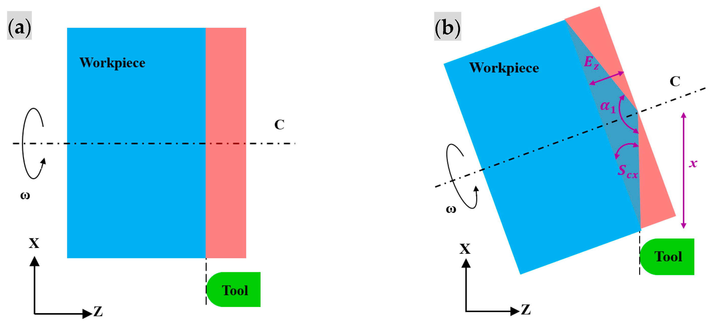
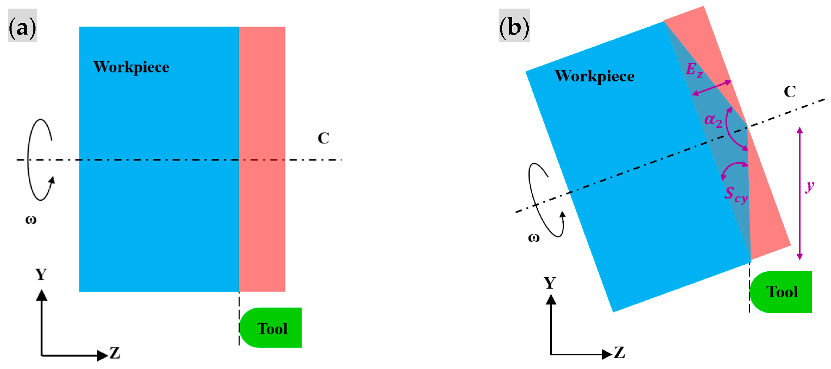
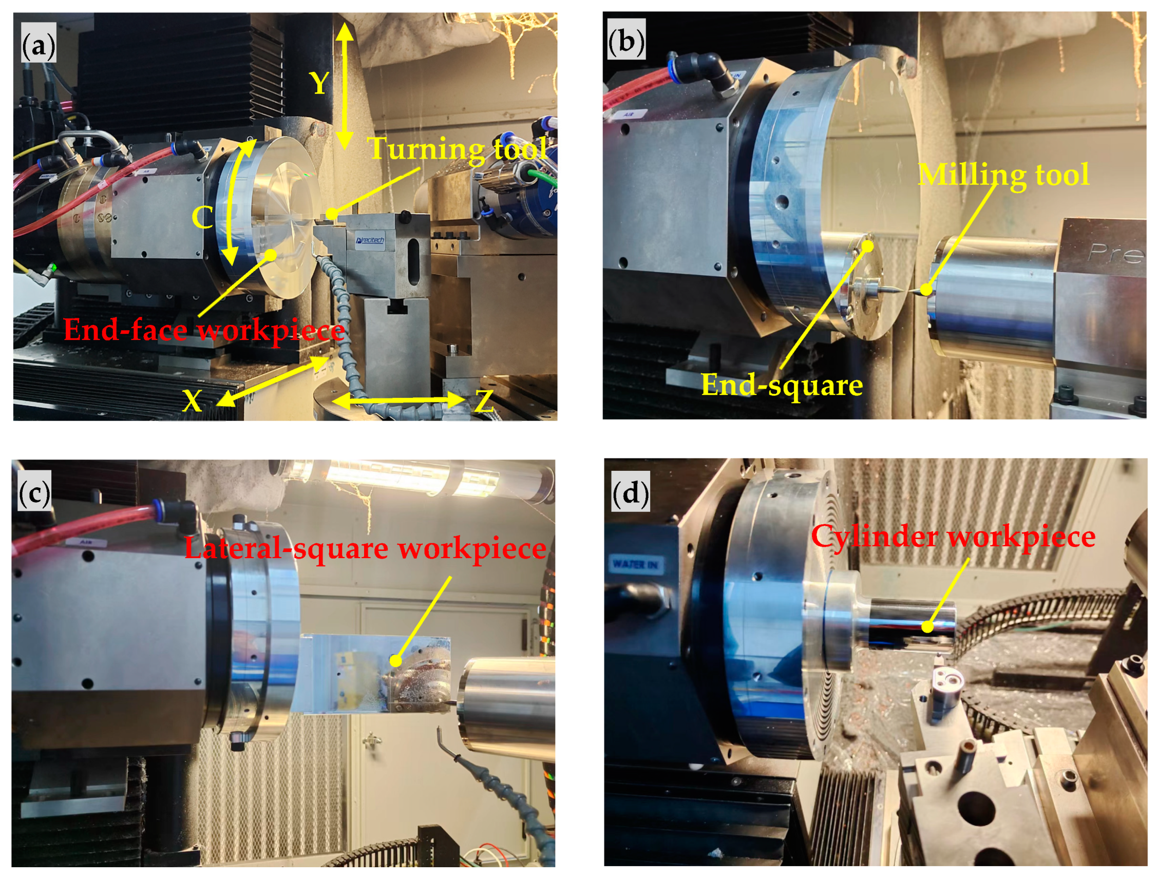
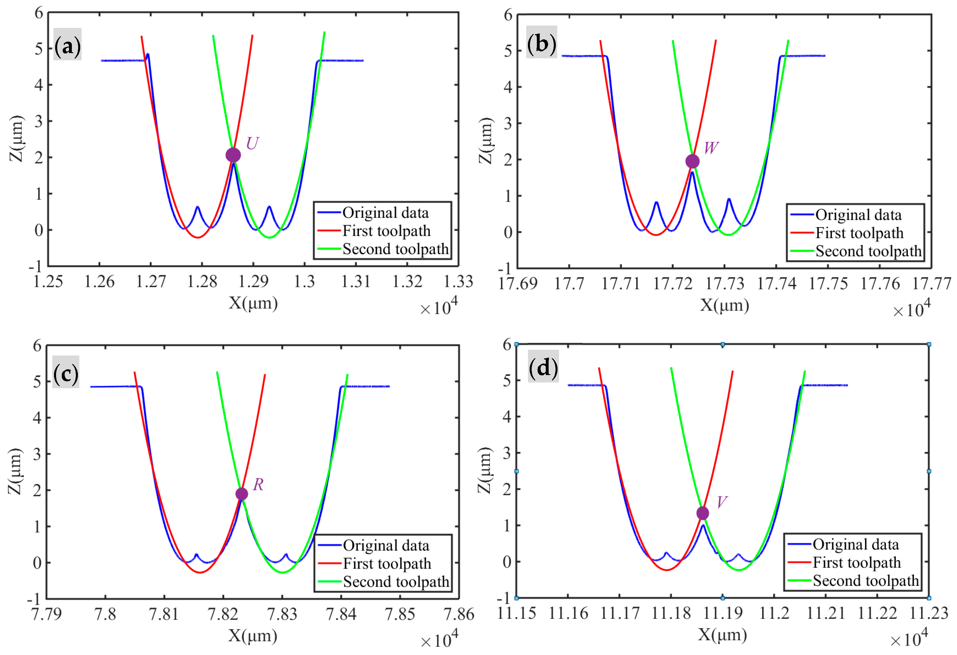
3.1. Specific Squareness Errors Scx and Scy under End-Face Turning
Following Equation (7), the volumetric error Ez is related with two squareness errors, Scx and Scy, of the C-axis, and the moving distances x of the X-axis, and y of the Y-axis. To recognize only the specific squareness error Scx, a featured structure is proposed for end-face turning along the X-direction, where the Y-axis moving distance is fixed at 0, as shown in Figure 2. Resultantly, Equation (7) is further simplified as:
Figure 2.
End-face turning along the X-direction for the featured structure: (a) Scx = 0, (b) Scx ≠ 0.
Under end-face turning, the volumetric error Ez is its resulting machining form error, which would be obtained through measuring the machined surface, i.e., a taper surface, at a taper angle α1, as shown in Figure 2. Resultantly, the squareness error Scx is expressed as:
Similarly, for the squareness error Scy, the same featured structure is designed for end-face turning along the Y-direction, where the X-axis moving distance is fixed at 0. Resultantly, Equation (7) is further simplified as:
Under end-face turning, the volumetric error Ez would be obtained via measuring the machined taper surface at a taper angle α2, as shown in Figure 3. Resultantly, the squareness error Scy is expressed as:
Figure 3.
End-face turning along the Y-direction for the featured structure: (a) Scy = 0, (b) Scy ≠ 0.
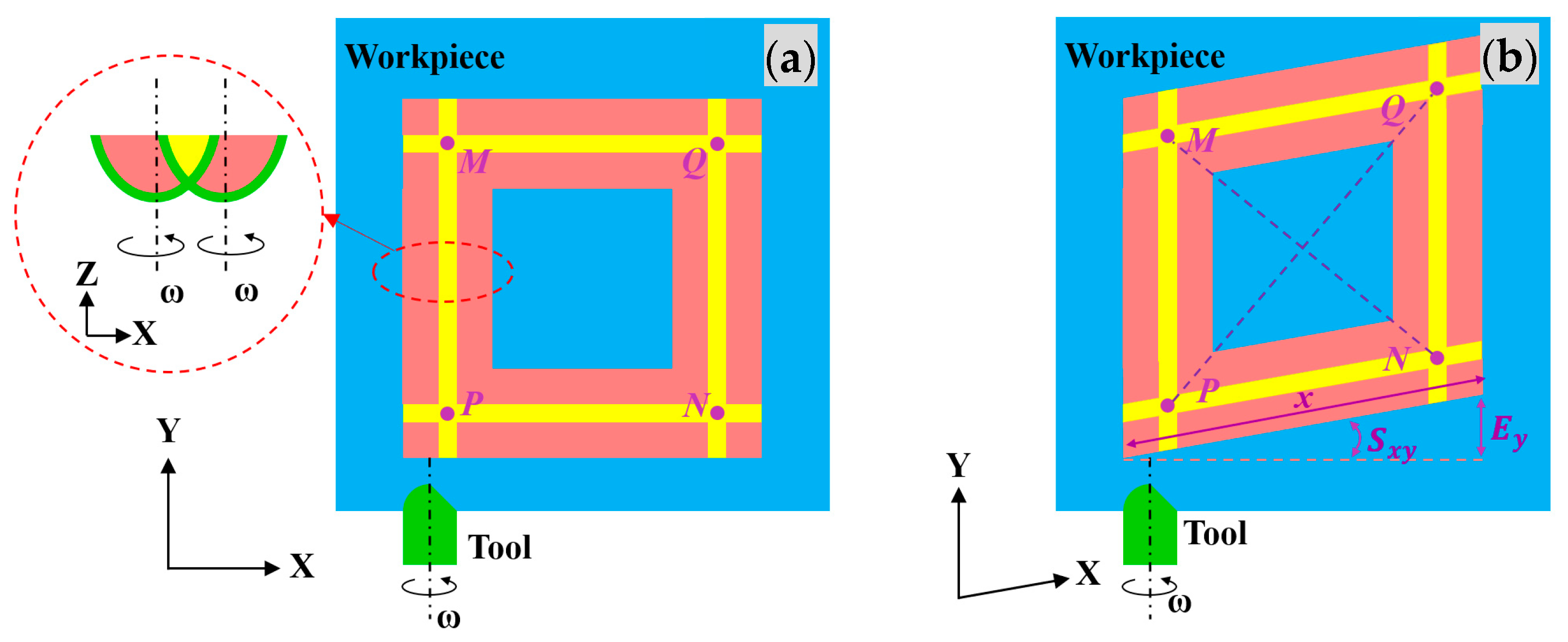
3.2. Specific Squareness Error Sxy under End-Square Milling
Following Equations (5) and (6), the volumetric errors Ex and Ey are related with five squareness errors Sxy, Syz, Scy, Sxz, and Scx, the moving distances x of the X-axis and z of the Z-axis, and the rotating angle θc of the C-axis. To recognize the specific squareness error Sxy, a featured structure is proposed for end-square milling in the X–Y plane, where the C-axis is fixed at the rotating angle of 0, and the Z-axis moving distance is the cutting depth, hence regarded as the infinitesimal, as shown in Figure 4. Resultantly, the volumetric error Ex in Equation (5) can be ignored, and Equation (6) is further simplified as:
Figure 4.
End-square milling in the X–Y plane for the featured structure: (a) Sxy = 0; (b) Sxy ≠ 0.
Under end-square milling, the volumetric error Ey is its resulting machining form error, which would be obtained via measuring the form of the machined square, i.e., a rhombus, at two diagonal lengths LMN and LPQ (the purple dashed line in Figure 4). The lengths are obtained from the position information of four vertices, which are recorded via the intersections of the residues of the two toolpaths (the yellow part of Figure 4). Resultantly, the squareness error Scx is expressed as:
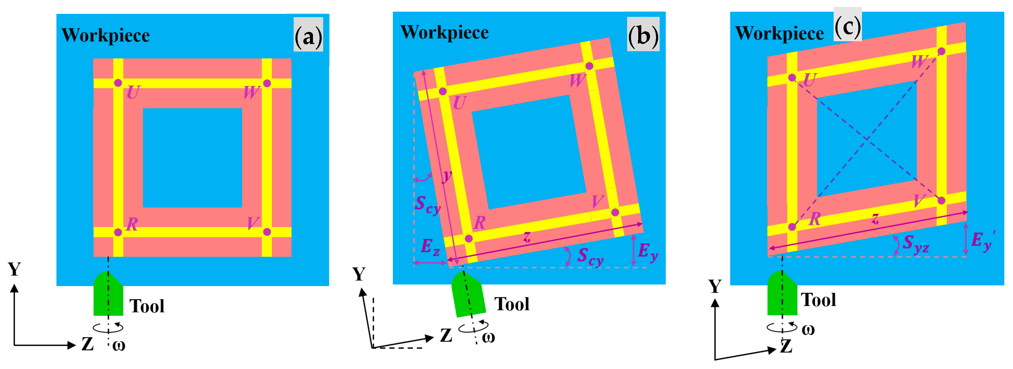
3.3. Specific Squareness Error Syz under Lateral-Square Milling
Following Equations (6) and (7), the volumetric errors Ey and Ez are related with five squareness errors Sxy, Syz, Scy, Sxz, and Scx, the moving distances x, y, and z of the X-, Y-, and Z-axes, and the rotating angle θc of the C-axis. To recognize the specific squareness error Syz, a featured structure is proposed for lateral-square milling in the Y–Z plane, where the C-axis is fixed at the rotating angle of 0, the X-axis moving distance is the cutting depth, hence regarded as the infinitesimal, and the Y- and Z-axis moving distances are equal, as shown in Figure 5. Resultantly, Equations (6) and (7) are, respectively, simplified as:
Figure 5.
Lateral-square milling in the Y–Z plane as the featured structure: (a) Syz = 0 and Scy = 0, (b) Syz = 0 but Scy ≠ 0, (c) Scy = 0 but Syz ≠ 0.
The simplified volumetric errors are still related with two squareness errors Scy and Syz, and the Z-axis moving distance. The squareness error Scy only makes the designed featured structure rotate around the machined square at a certain angle without any geometric changes, as shown in Figure 5b, while the squareness error Syz changes it into a rhombus, as shown in Figure 5c. Accordingly, only considering its form accuracy, the volumetric error Ez in Equation (15) could be ignored, so that Equation (14) is further simplified as:
Under lateral-square milling, the volumetric error Ey would be obtained via measuring the form of the machined square at two diagonal lengths LUV and LRW, as shown in Figure 5c. Resultantly, the squareness error Syz is expressed as:
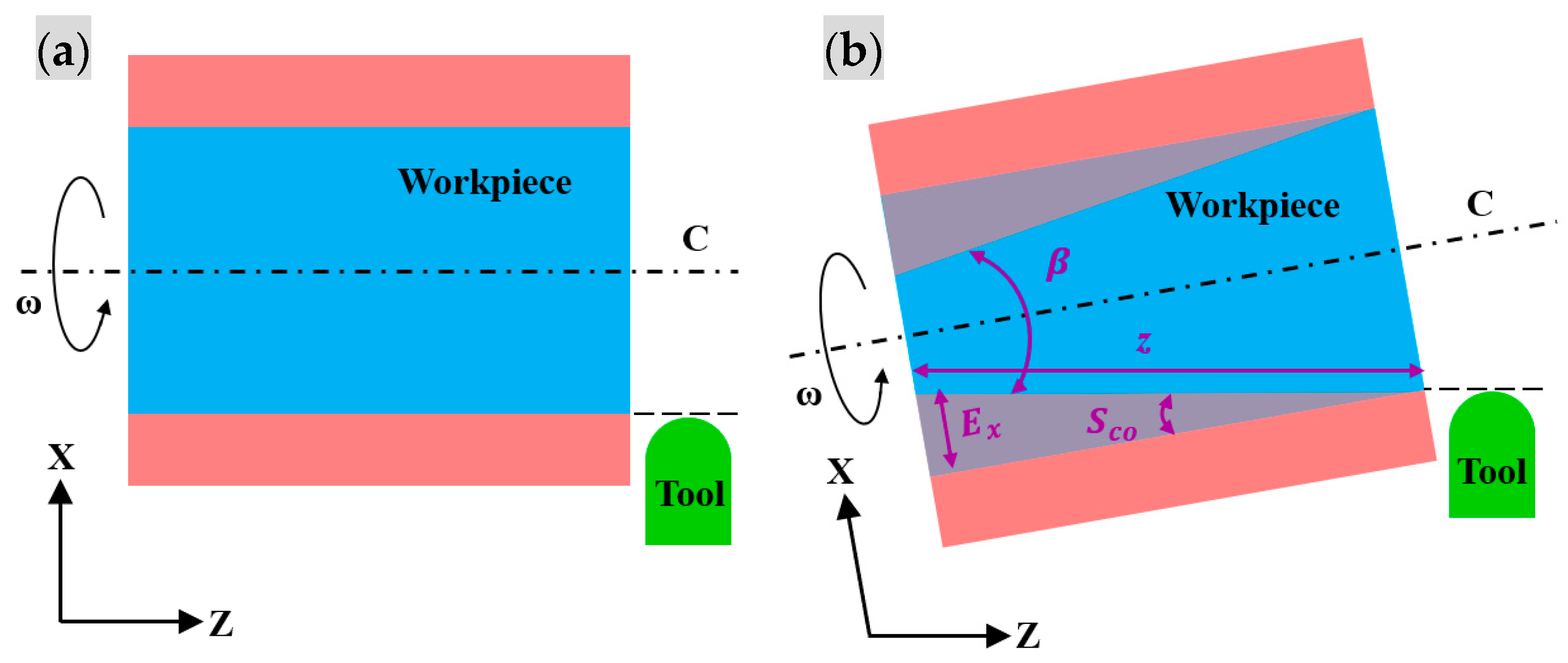
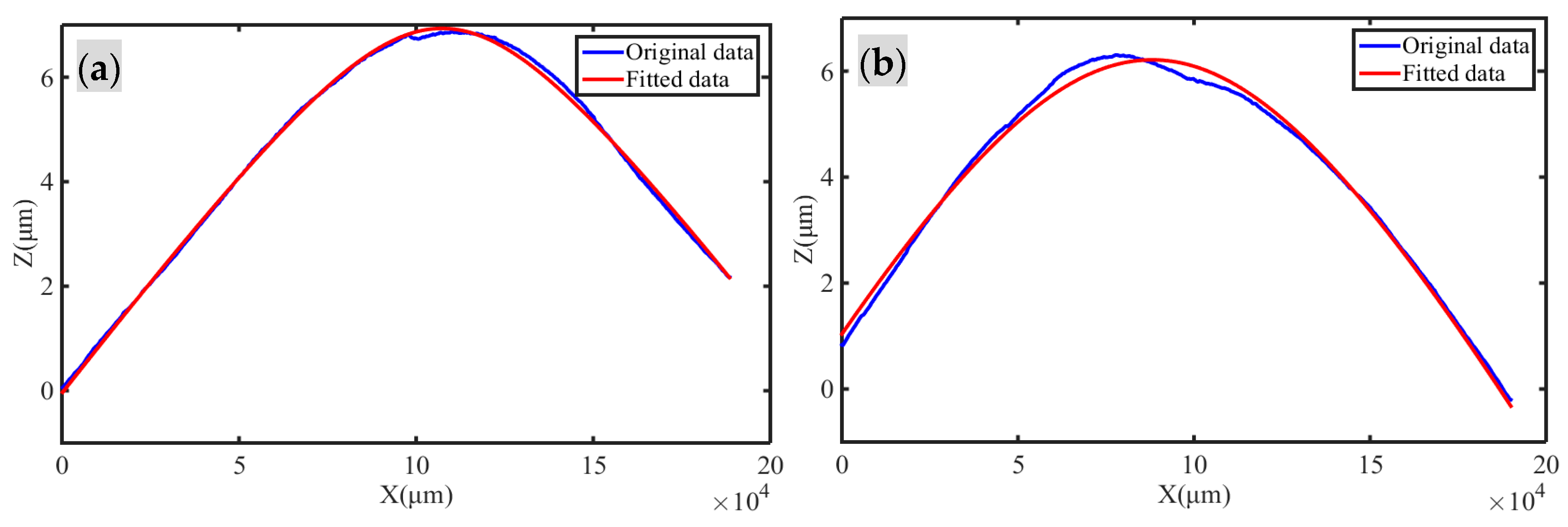
3.4. Specific Squareness Error Sxz under Cylinder Turning
Following Equations (5) and (6), in order to recognize the specific squareness error Sxz, a featured structure is proposed for cylinder turning along the Z-direction, where the X-axis moving distance is the cutting depth, hence regarded as the infinitesimal, as shown in Figure 6. Besides, the volumetric errors Ex and Ey of Equations (5) and (6) in the Cartesian coordinate system are transformed into the volumetric error Er along the radial direction in the cylindrical coordinate system, via the expression Er = Ex·cosθc + Ey·sinθc []. Resultantly, the volumetric error Er is expressed as:
where is the phase angle and it is given by . During the cylinder turning process, the rotating angle of the C-axis θc changes rapidly, while the Z-axis moves relatively slowly. Accordingly, the volumetric error Er is further maximized as:
where . Under cylinder turning, the volumetric error Er is its resulting machining form error, which would be obtained via measuring the machined surface, i.e., a cone, at a taper angle β, as shown in Figure 6. Resultantly, the squareness error Sco is expressed as:
Figure 6.
Cylinder turning along the Z-direction for the featured structure: (a) Scz = 0, (b) Scz ≠ 0.
Finally, the squareness error Sxz is expressed as:
4. Experimental Setup
The above-designed featured structures were machined under end-face turning, end-square milling, lateral-square milling, and cylinder turning on a four-axis UPM machine, respectively. It includes the X-axis, Y-axis, Z-axis, and C-axis for diamond turning, micro-milling, micro-grinding, and grooving non-rotationally symmetric surfaces, as shown in Figure 7. The surface roughness of its turning is less than 1.5 nm, and the form accuracy is less than 0.125 μm, and the surface roughness of its milling is less than 10 nm, and the shape error is less than 0.2 μm. The machining conditions are listed in Table 3 and Table 4. Firstly, a disc-type workpiece was employed, with a diameter of 210 mm, for end-face turning and end-square milling, respectively. Secondly, a bar-type workpiece was used, with a length of 200 mm and a width of 80 mm, for lateral-square milling. Additionally, a cylinder-type workpiece was utilized, with a diameter of 38 mm and a length of 70 mm, for cylinder turning. Further, the step distances between two toolpaths were 100 μm for end-square milling and lateral-square milling, respectively. Finally, the machined featured structures were measured using a high-resolution 3D freeform profilometer. Its probe has a measurement resolution of 0.8 nm and can be used in surface finish and form analysis for the freeform surfaces of high-precision optical components.
Figure 7.
UPM experiments for the featured structures under: (a) end-face turning for Scx or Scy, (b) end-square milling for Sxy, (c) lateral-square milling for Syz, (d) cylinder turning for Sxz.
Table 3.
Machining parameters.
Table 4.
Tool geometric parameters.
5. Results and Discussion
To recognize the specific squareness errors Scx and Scy, the machining form errors under end-face turning along the X- or Y-directions under the machining conditions of Table 3 and Table 4 were measured and extracted, as shown in Figure 8. Whether turning along the X-direction or Y-direction, the surface profiles are not the lines, but the tapered curves, and their taper heights are about 6 µm at the feed distance of 105 mm. Fitted via the least-square method, the taper angles α1 and α2 were obtained at 179.9896° and 179.9858° (Table 5), respectively. According to Equations (9) and (11), the specific squareness errors Scx and Scy were 18.72″ and −25.56″, respectively, as shown in Table 6. The results verify that the featured structures under end-face turning could be greatly amplified to recognize the specific squareness errors Scx and Scy.
Figure 8.
The measured taper angles under end-face turning for Scx and Scy: (a) α1 along the X-direction, (b) α2 along the Y-direction.
Table 5.
The results of the featured structures for the specific squareness errors.
Table 6.
The specific squareness errors for the crucial PIGEs.
Additionally, to recognize the specific squareness error Sxy, the machining form error under end-square milling in the X–Y plane at the machining conditions of Table 3 and Table 4 was measured and extracted, as shown in Figure 9. The two diagonal lengths, LMN and LPQ, are 98,996.126 µm and 99,003.545 µm (Table 5) at the noticeable difference of 7.419 µm, which indicates that the machined square was deformed into a rhombus. According to Equation (13), the specific squareness error Sxy is 15.46″, as shown in Table 6. The results prove that the featured structures under end-square milling would be significantly designed to recognize the specific squareness error Sxy.
Figure 9.
The measured diagonal lengths under end-face square milling for Sxy: (a) M for LMN, (b) Q for LPQ, (c) P for LPQ, and (d) N for LMN.
Further, to recognize the specific squareness error Syz, the machining form error under lateral-square milling in the Y–Z plane at the machining conditions of Table 3 and Table 4 was measured and extracted, as shown in Figure 10. The two diagonal lengths, LUV and LRW, are 99,000.582 µm and 99,008.822 µm (Table 5) at the significant difference of 8.240 µm, which identifies that the machined square was deformed into a rhombus. According to Equation (17), the specific squareness error Syz is 17.17″, as presented in Table 6. The results confirm that the featured structures under lateral-square milling would be dramatically designed to recognize the specific squareness error Sxy.
Figure 10.
The measured diagonal lengths under lateral-square milling for Syz: (a) U for LUV, (b) W for LRW, (c) R for LRW, and (d) V for LUV.
Finally, to recognize the specific squareness error Sxz, the machining form error under cylinder turning along the Z-direction at the machining conditions of Table 3 and Table 4 was measured and extracted, as shown in Figure 11. After fitting, the taper angle β was 19.80″ (Table 5), which means that the machined cylinder was deformed into a cone. According to Equation (21), the specific squareness error Sxz was 23.98″, as listed in Table 6. The results support the theory that the featured structures under cylinder turning could be prominently designed to recognize the specific squareness error Sxz.
Figure 11.
The measured taper angle β under cylinder turning for Sxz: (a) the measured topography, and (b) the fitted topography.
Overall, a series of UPM and measuring experiments have been carried out for the featured structures. The five specific squareness errors for the crucial PIGEs have be obtained effectively from the machining form errors of the designed featured structures under end-face turning, end-face milling, lateral-square milling, and cylinder turning, respectively. The results effectively support the new proposed method with the featured structures for the efficient identification of crucial PIGEs, which could be employed for compensation to enhance machining accuracy.
6. Conclusions
In ultra-precision machining (UPM), position-independent geometric errors (PIGEs), called squareness errors, serve as a key factor affecting the form accuracy of a machined surface. To improve the form accuracy, more research work has been conducted on the identification of PIGEs. However, the currently used identification methods cannot accurately recognize specific squareness errors for crucial PIGEs, due to the lack of consideration of form errors under the machining process. In this study, a new method with featured structures was proposed, to identify crucial PIGEs in UPM. The main conclusions are drawn as follows:
- (1)
- A volumetric error model has been proposed for PIGEs, to significantly reveal the relationship between the five squareness errors and their resulting machining form errors in UPM. The volumetric error is coupled with other squareness errors, and changes with the motion position along each axis.
- (2)
- Moreover, the featured structures have been designed, machined, and measured to efficiently decouple the specific squareness errors from their form errors in UPM, and to successfully recognize crucial PIGEs. The values of the five specific squareness errors identified are between 15″ and 26″.
- (3)
- Further, it is a potential means to improve the form accuracy of UPM, through the identification of crucial PIGEs with compensation.
The innovation in this paper is that it proposes a new method with featured structures to identify the specific squareness errors for crucial PIGEs in UPM. This method not only considers the influence of PIGEs on the actual machinery, but also effectively decouples the specific squareness errors from the machining form errors, realizing the accurate recognition of crucial PIGEs.
Author Contributions
L.Z.: Conceptualization, Methodology, Investigation, Data curation, Writing—original draft. S.Z.: Resources, Validation, Writing—review and editing, Supervision, Project administration. All authors have read and agreed to the published version of the manuscript.
Funding
This research partially received a grant from the National Natural Science Foundation of China (Grant No. 51405217).
Data Availability Statement
Data will be made available on request.
Conflicts of Interest
The authors declared no potential conflicts of interest with respect to the research, authorship, and/or publication of this article.
References
- Wang, H.; To, S.; Chan, C.Y. Investigation on the influence of tool-tip vibration on surface roughness and its representative measurement in ultra-precision diamond turning. Int. J. Mach. Tools Manuf. 2013, 69, 20–29. [Google Scholar] [CrossRef]
- Geng, Z.; Tong, Z.; Jiang, X. Review of geometric error measurement and compensation techniques of ultra-precision machine tools. Light Adv. Manuf. 2021, 2, 211–227. [Google Scholar] [CrossRef]
- Xing, T.; Zhao, X.; Song, L.; Cui, Z.; Zou, X.; Sun, T. On-machine measurement method and geometrical error analysis in a multi-step processing system of an ultra-precision complex spherical surface. J. Manuf. Process. 2022, 80, 161–177. [Google Scholar] [CrossRef]
- Guo, P.; Li, Z.; Xiong, Z.; Zhang, S. A theoretical and experimental investigation into tool setting induced form error in diamond turning of micro-lens array. Int. J. Adv. Manuf. Technol. 2023, 124, 2515–2525. [Google Scholar] [CrossRef]
- Wu, L.; Liu, H.; Zong, W. Analysis and compensation for the dominant tool error in ultra-precision diamond ball-end milling. J. Mater. Process. Technol. 2023, 318, 118034. [Google Scholar] [CrossRef]
- Sun, L.; Ren, M.; Hong, H.; Yin, Y. Thermal error reduction based on thermodynamics structure optimization method for an ultra-precision machine tool. Int. J. Adv. Manuf. Technol. 2017, 88, 1267–1277. [Google Scholar] [CrossRef]
- Fedorynenko, D.; Nakao, Y. Evaluation of thermal stability of ultra-precision water-lubricated spindle. Precis. Eng. 2023, 80, 127–137. [Google Scholar] [CrossRef]
- Chen, G.D.; Sun, Y.Z.; Zhang, F.H.; Lu, L.H.; Chen, W.Q.; Yu, N. Dynamic accuracy design method of ultra-precision machine tool. Chin. J. Mech. Eng. 2018, 31, 8. [Google Scholar] [CrossRef]
- He, S.; Wu, J.; Xuan, J.; Du, W.; Xia, Q.; Zhang, L.; Shi, T. Freeform surface topography model for ultraprecision turning under the influence of various errors. J. Manuf. Process. 2021, 71, 429–449. [Google Scholar] [CrossRef]
- Gu, J.; Agapiou, J.S.; Kurgin, S. CNC machine tool work offset error compensation method. J. Manuf. Syst. 2015, 37, 576–585. [Google Scholar] [CrossRef]
- ISO230-1; Test Code for Machine Tools-Part 1: Geometric Accuracy of Machines Operating under No-Load or Quasi-Static Conditions. ISO, BS: Geneva, Switzerland, 2012.
- ISO230-7; Test Code for Machine Tools-Part 7: Geometric Accuracy of Axes of Rotation. ISO, BS: Geneva, Switzerland, 2015.
- Lee, K.I.; Yang, S.H. Robust measurement method and uncertainty analysis for position-independent geometric errors of a rotary axis using a double ball-bar. Int. J. Precis. Eng. Manuf. 2013, 14, 231–239. [Google Scholar] [CrossRef]
- Jiang, X.; Cripps, R.J. A method of testing position independent geometric errors in rotary axes of a five-axis machine tool using a double ball bar. Int. J. Mach. Tools Manuf. 2015, 89, 151–158. [Google Scholar] [CrossRef]
- Chen, Q.; Maeng, S.; Li, W.; Zhou, Z.; Min, S. Geometric-and force-induced errors compensation and uncertainty analysis of rotary axis in 5-axis ultra-precision machine tool. Int. J. Adv. Manuf. Technol. 2020, 109, 841–856. [Google Scholar] [CrossRef]
- Osei, S.; Wang, W.; Ding, Q. A new method to identify the position-independent geometric errors in the rotary axes of five-axis machine tools. J. Manuf. Process. 2023, 87, 46–53. [Google Scholar] [CrossRef]
- Lai, T.; Peng, X.; Tie, G.; Liu, J.; Guo, M. High accurate squareness measurement squareness method for ultra-precision machine based on error separation. Precis. Eng. 2017, 49, 15–23. [Google Scholar] [CrossRef]
- Maeng, S.; Min, S. Simultaneous geometric error identification of rotary axis and tool setting in an ultra-precision 5-axis machine tool using on-machine measurement. Precis. Eng. 2020, 63, 94–104. [Google Scholar] [CrossRef]
- Liu, Y.; Ding, F.; Li, D.; Wu, Y.; Xue, J.; Wang, W.; Wang, B. Machining accuracy improvement for a dual-spindle ultra-precision drum roll lathe based on geometric error analysis and calibration. Precis. Eng. 2020, 66, 401–416. [Google Scholar] [CrossRef]
- Chen, Q.; Li, W.; Jiang, C.; Zhou, Z.; Min, S. Separation and compensation of geometric errors of rotary axis in 5-axis ultra-precision machine tool by empirical mode decomposition method. J. Manuf. Process. 2021, 68, 1509–1523. [Google Scholar] [CrossRef]
- Song, L.; Zhao, X.; Zhang, Q.; Shi, D.; Sun, T. A geometric error measurement method for five-axis ultra-precision machine tools. Int. J. Adv. Manuf. Technol. 2023, 126, 1379–1395. [Google Scholar] [CrossRef]
- Gao, H.; Fang, F.; Zhang, X. Reverse analysis on the geometric errors of ultra-precision machine. Int. J. Adv. Manuf. Technol. 2014, 73, 1615–1624. [Google Scholar] [CrossRef]
- Pezeshki, M.; Arezoo, B. Kinematic errors identification of three-axis machine tools based on machined work pieces. Precis. Eng. 2016, 43, 493–504. [Google Scholar] [CrossRef]
- Liu, X.; Zhang, X.; Fang, F.; Liu, S. Identification and compensation of main machining errors on surface form accuracy in ultra-precision diamond turning. Int. J. Mach. Tools Manuf. 2016, 105, 45–57. [Google Scholar] [CrossRef]
- Li, Y.; Zhang, Y.; Lin, J.; Yi, A.; Zhou, X. Effects of Machining Errors on Optical Performance of Optical Aspheric Components in Ultra-Precision Diamond Turning. Micromachines 2020, 11, 331. [Google Scholar] [CrossRef]
- Tao, H.; Chen, R.; Xuan, J.; Xia, Q.; Yang, Z.; Zhang, X.; Shi, T. A new approach to identify geometric errors directly from the surface topography of workpiece in ultra-precision machining. Int. J. Adv. Manuf. Technol. 2020, 106, 5159–5173. [Google Scholar] [CrossRef]
- Zha, J.; Villarrazo, N.; Martínez de Pisson, G.; Li, Y.; Zhang, H.; López de Lacalle, L.N. An accuracy evolution method applied to five-axis machining of curved surfaces. Int. J. Adv. Manuf. Technol. 2023, 125, 3475–3487. [Google Scholar] [CrossRef]
- Yang, S.H.; Lee, K.I. Machine tool analyzer: A device for identifying 13 position-independent geometric errors for five-axis machine tools. Int. J. Adv. Manuf. Technol. 2021, 115, 2945–2957. [Google Scholar] [CrossRef]
- Chen, G.; Liang, Y.; Sun, Y.; Chen, W.; Wang, B. Volumetric error modeling and sensitivity analysis for designing a five-axis ultra-precision machine tool. Int. J. Adv. Manuf. Technol. 2013, 68, 2525–2534. [Google Scholar] [CrossRef]
- Tao, H.; Chen, R.; Xuan, J.; Xia, Q.; Yang, Z.; Zhang, X.; Shi, T. Prioritization analysis and compensation of geometric errors for ultra-precision lathe based on the random forest methodology. Precis. Eng. 2020, 61, 23–40. [Google Scholar] [CrossRef]
Disclaimer/Publisher’s Note: The statements, opinions and data contained in all publications are solely those of the individual author(s) and contributor(s) and not of MDPI and/or the editor(s). MDPI and/or the editor(s) disclaim responsibility for any injury to people or property resulting from any ideas, methods, instructions or products referred to in the content. |
© 2023 by the authors. Licensee MDPI, Basel, Switzerland. This article is an open access article distributed under the terms and conditions of the Creative Commons Attribution (CC BY) license (https://creativecommons.org/licenses/by/4.0/).