Article

Rotor Asymmetry Detection in Wound Rotor Induction Motor Using Kalman Filter Variants and Investigations on Their Robustness: An Experimental Implementation

by
Furzana John Basha
* and
Kumar Somasundaram
Department of Instrumentation Engineering, Madras Institute of Technology Campus, Anna University, Chromepet, Chennai 600044, India
*
Author to whom correspondence should be addressed.
Machines 2023, 11(9), 910; https://doi.org/10.3390/machines11090910
Submission received: 10 August 2023 / Revised: 8 September 2023 / Accepted: 11 September 2023 / Published: 14 September 2023
(This article belongs to the Section Electrical Machines and Drives)

Abstract

:
This paper analyzes the performance of Kalman filter-based estimators for robust filtering and rotor asymmetry detection in wound rotor induction machines (WRIMs) using real-time data. Filter models were designed based on an extended model of WRIMs. The detection of rotor asymmetry was achieved by estimating the states of rotor resistance and speed using four filters. The sensitivity of the parameters under healthy and asymmetry conditions was thoroughly analyzed and categorized as low, medium, and high sensitivity parameters. Robust model-based estimators were designed to minimize the probability of false alarms. The performance analysis demonstrated that the dual unscented Kalman filter (DUKF) outperformed other Kalman filters such as the extended Kalman filter (EKF), dual extended Kalman filter (DEKF), and unscented Kalman filter (UKF) for state estimation of WRIM.

1. Introduction

Wound rotor induction machines (WRIMs) have been widely employed in various industrial applications due to their robustness and ability to handle high starting torque requirements. In recent times, WRIMs have received special attention due to their wide utilization in electrical power generation, particularly as double-fed induction generators (DFIGs) in variable speed wind turbines [1]. However, despite their widespread use, WRIMs are prone to various operational challenges, one of which is electrical rotor asymmetry.
Rotor faults are the most significant faults as they cause secondary failures that can lead to serious motor malfunctions. The effect of rotor faults is associated with broken rotor bars [2,3,4] and cracked end rings [5] in squirrel cage induction motors, as well as rotor winding impedances [6,7,8] in wound rotor induction motors. Electrical rotor asymmetry refers to an imbalance in the electrical characteristics of the rotor windings. Electrical rotor asymmetry can arise from several factors, including variations in the resistance and inductance of the rotor windings. These variations can be caused by manufacturing defects, winding damage, or changes in the motor’s operating conditions [9,10]. Electrical rotor asymmetry can have significant consequences on the motor’s performance and reliability. It may lead to uneven torque production, reduced efficiency, increased losses, and variations in motor speed [11]. Furthermore, electrical rotor asymmetry can cause abnormal heating and stress on motor components, potentially resulting in premature failures [12]. Consequently, developing efficient and reliable techniques for detecting rotor asymmetry has become a subject of utmost importance in the field of motor diagnostics and maintenance.
Techniques for detecting rotor asymmetry in WRIMs can be achieved using either model-based or signal-based approaches. Signal-based approaches are widely available in the literature. Stator current is directly influenced by rotor asymmetry fault (RAF), and rotor current is directly influenced by stator asymmetry fault (SAF) [13]. Initially, the motor current signature analysis (MCSA) method has been used to diagnose faults in electrical motors using current analysis. More recently, diagnostic techniques based on the analysis of stator current have been developed using methods such as continuous wavelet transform (CWT) and iterative localized discrete Fourier transform (IDFT) [14], instantaneous frequency analysis [15], stator current space vector magnitude (SCSVM), and instantaneous magnitude of the stator current (IMSC) [13], which are good indicators for RAF monitoring. To extract the defective signature component from current signals, the extended Kalman filter (EKF) provided better results than CWT and IDFT [14]. The RAF index is calculated by multiplying the original stator current signal by a function of the dominant frequency of the original signal [15]. A low level of asymmetry was reliably diagnosed during non-stationary operation by extracting the instantaneous frequency of faulty stator currents [7].
On the other hand, model-based approaches are widely used to detect rotor faults in squirrel cage induction motors (SCIMs). Rotor asymmetry faults were detected in a wind turbine by [16], where there is more scope for detecting rotor asymmetry faults (RAFs) in WRIMs using the model-based approach.
An observer constitutes a dynamic mechanism that provides estimations of the current state of a system, utilizing prior information about its inputs and outputs. The Kalman filter, an extensively employed optimal observer, estimates the state of a dynamic system by considering both the system model and the measurements from sensors. From the available literature, apart from the Kalman filter, high-gain and adaptive observers have been utilized. A high-gain observer amplifies estimation sensitivity, rendering it effective in scenarios with limited sensor measurements or significant noise. The adaptive observer adjusts its parameters based on real-time data, ensuring reliable estimation even when the system dynamics change over time.
The Kalman filter is used in the proposed work. The extended Kalman filter (EKF) is useful for nonlinear systems and is easy to implement. However, it might not work well in situations with a lot of uncertainty. The unscented Kalman filter (UKF) is more accurate for nonlinear systems and handles uncertainty more effectively, but it can become complex in high-dimensional situations.
Since rotor asymmetry is detected by observing variations in rotor resistance [17], estimating rotor resistance through model-based approaches is performed. The extended Kalman filter (EKF) is employed in model-based methods for detecting broken rotor bars in induction motors [4,17]. Ref. [18] estimated speed using EKF, UKF, and NSF (neural state filter) for squirrel cage induction motors (SCIMs). Additionally, model-based approaches demonstrated the capability to overcome performance issues at extremely low and zero speeds [9].
Based on the literature, the detection of rotor electrical asymmetry using model-based approaches is described by [16]. The author chose the unscented Kalman filter (UKF) to detect the fault. Numerous works on signal-based methods to detect rotor asymmetry have been proposed. As demonstrated in this work, there is a considerable scope in the model-based approach owing to its capability to accurately capture the motor’s dynamics. The model-based approach utilizes an extended state space model with load torque and rotor resistance as additional states. The motor’s parameters include stator resistance (Rs), rotor resistance (Rr), stator inductance (Ls), rotor inductance (Lr), and mutual inductance (Lm).
To summarize, the proposed work comprises four key aspects:
  • Analytically calculating parameters for the real-time mathematical model of a WRIM through standardized tests.
  • Rotor asymmetry fault resulting from changes in Rr also affects the motor’s speed. Therefore, both Rr and speed are estimated using various variants of Kalman filters (EKF, UKF, DEKF, DUKF). The developed Kalman filters for state estimation are applied to real-time data, tested, and validated through filter convergence using the kurtosis method.
  • Qualitative analysis of the robustness of different filter variants is conducted by performing state estimation on real-time data under both healthy and asymmetric conditions. The estimation is carried out with consistent initial conditions and different initial conditions.
  • A significant contribution of this work lies in the parameter sensitivity analysis used to minimize the probability of false alarms.
The paper is organized as follows: Section 2 presents the mathematical modeling of WRIM and the methodology for rotor asymmetry detection using EKF, UKF, DEKF, and DUKF. Section 3 presents the results and discussion on state estimation and analysis of healthy and asymmetric rotor detection, robustness analysis, parameter sensitivity analysis, filter convergence, and accuracy under various operating conditions. Finally, inferences are presented in the concluding section.

2. Materials and Methods

The chosen WRIM is a versatile three-phase multi-functional machine equipped with a slip-ring rotor. This inherent flexibility enables the machine to serve as either an asynchronous or synchronous motor or generator, as shown in Figure 1. The distinct terminals of the rotor designated as K, L, and M are clearly identified in Figure 1b. These terminals possess unique attributes due to the varying winding configurations associated with each. This adaptability enables the WRIM to operate effectively in synchronous or asynchronous modes. The experimental investigations described in the study are conducted while the machine operates in its asynchronous motor mode. This operational mode denotes the machine performing as an asynchronous motor during the experiments. To replicate a state of a healthy rotor, the K-L-M terminals are shorted. This action likely symbolizes a balanced rotor condition where all three terminals are electrically linked, representing a symmetric setup. Conversely, to imitate an asymmetrical condition, the K-M terminals are shorted. This configuration implies that the K and M terminals are electrically connected. This arrangement serves to mimic a situation where rotor asymmetry is introduced. Table 1 presents specifications for the WRIM operating in an asynchronous motor mode, outlining the motor’s nameplate information for this particular mode.

2.1. Mathematical Modelling of WRIM

In general, for state observation using EKF and UKF, the augmented state space model of the induction motor with five state variables is considered in an arbitrary reference frame [19]. However, in this work, an extended state space model with seven state variables is employed for offline estimation. Here, the sixth state variable represents the motor load torque (TL), and the seventh state variable is the rotor resistance (Rr). The extended state space model and the output equation of the three-phase wound rotor induction motor are provided in Equations (1) and (2), respectively.
i d s . i q s . Ψ d r . Ψ q r . ω m . T L . R r . = R s L σ + R r L m 2 L r 2 L σ 0 R r L m L r 2 L σ L m P ω m L σ L r 0 0 0 0 R s L σ + R r L m 2 L r 2 L σ L m P ω m L σ L r R r L m L r 2 L σ 0 0 0 R r L m L r 0 R r L r P ω m 0 0 0 0 R r L m L r P ω m R r L r 0 0 0 3 P 2 J L L m L r ψ q r 3 P 2 J L L m L r ψ d r 0 0 0 1 J L 0 0 0 0 0 0 0 0 0 0 0 0 0 0 0 i d s i q s Ψ d r Ψ q r ω m T L R r + 1 L σ 0 0 1 L σ 0 0 0 0 0 0 0 0 0 0 V ds V qs
i d s i q s = 1 0 0 0 0 0 0 0 1 0 0 0 0 0 i d s i q s ψ d r ψ q r ω m T L R r
The notations are defined as follows:
ids and iqs: Stator current components in stationary axis
Rs and Ls: Stator resistance and inductance, respectively
Vds and Vqs: Stator voltage components in stationary axis
ψdr and ψqr: Rotor flux linkage components in stationary axis
Rr and Lr: Rotor resistance and inductance referred to stator, respectively
P: No. of pole pairs
Lm: Mutual inductance
ωm: Rotor angular velocity
σ: Leakage factor
σ = 1 L m 2 L s L r
L σ = σ L s ;
JL: Total inertia of the induction motor
In order to determine the exact parameter values, a series of tests, including the DC resistance test, no-load test, and blocked rotor test [20], are undertaken. The following are the procedures to conduct those tests.
  • No-load test: The motor is run through this test at its rated voltage without any load. The purpose of this test is to determine the magnetizing inductance (Lm). By applying the rated voltage Vo, corresponding current Io and the power Wo is noted, the value of Lm is calculated using the following formula.
L m =   V s 2 π f s I m I m =   I o c o s o
2.
Blocked rotor test: The blocked rotor test is conducted to understand the performance of an induction motor when it is operating under full load conditions, similar to the short-circuit test. The objective of this test is to ascertain the values of stator inductance (Ls), rotor inductance (Lr), and rotor resistance (Rr). By applying the rated current (Isc) and recording the corresponding voltage (Vsc) and power (Wsc), the values of Ls, Lr, and Rr are calculated using the following formulas.
L l s + L l r =   Z s c       s i n s c 2 π f s
Assuming, L l s = L l r ,   L s = L l s + L m ; L r = L l r + L m
R r = Z s c       c o s s c   R s
3.
DC resistance test: By applying a DC voltage across two motor terminals and measuring the resulting current, it is possible to determine the stator resistance (Rs).
These tests are conducted for both healthy and asymmetrical rotor conditions. The healthy rotor emulation is achieved by shorting the K-L-M terminals, as previously mentioned. The motor’s current, voltage, and power are recorded during the execution of the aforementioned three tests. Similarly, to emulate an asymmetric condition, accomplished by shorting the K-M terminals, the same tests are carried out and the motor’s current, voltage, and power are recorded. Utilizing the equations provided below, equivalent circuit values are calculated, revealing variations in rotor resistances that confirm the asymmetry in the K-M connection. The parameter values resulting from these tests for both the healthy and asymmetry scenarios are outlined in Table 2.

2.2. Methodology

This work aims to identify rotor asymmetries through a model-based approach. In this method, the extended Kalman filter, unscented Kalman filter, dual extended Kalman filter, and dual unscented Kalman filter are employed to estimate the state of rotor resistance, enabling the detection of rotor asymmetry.

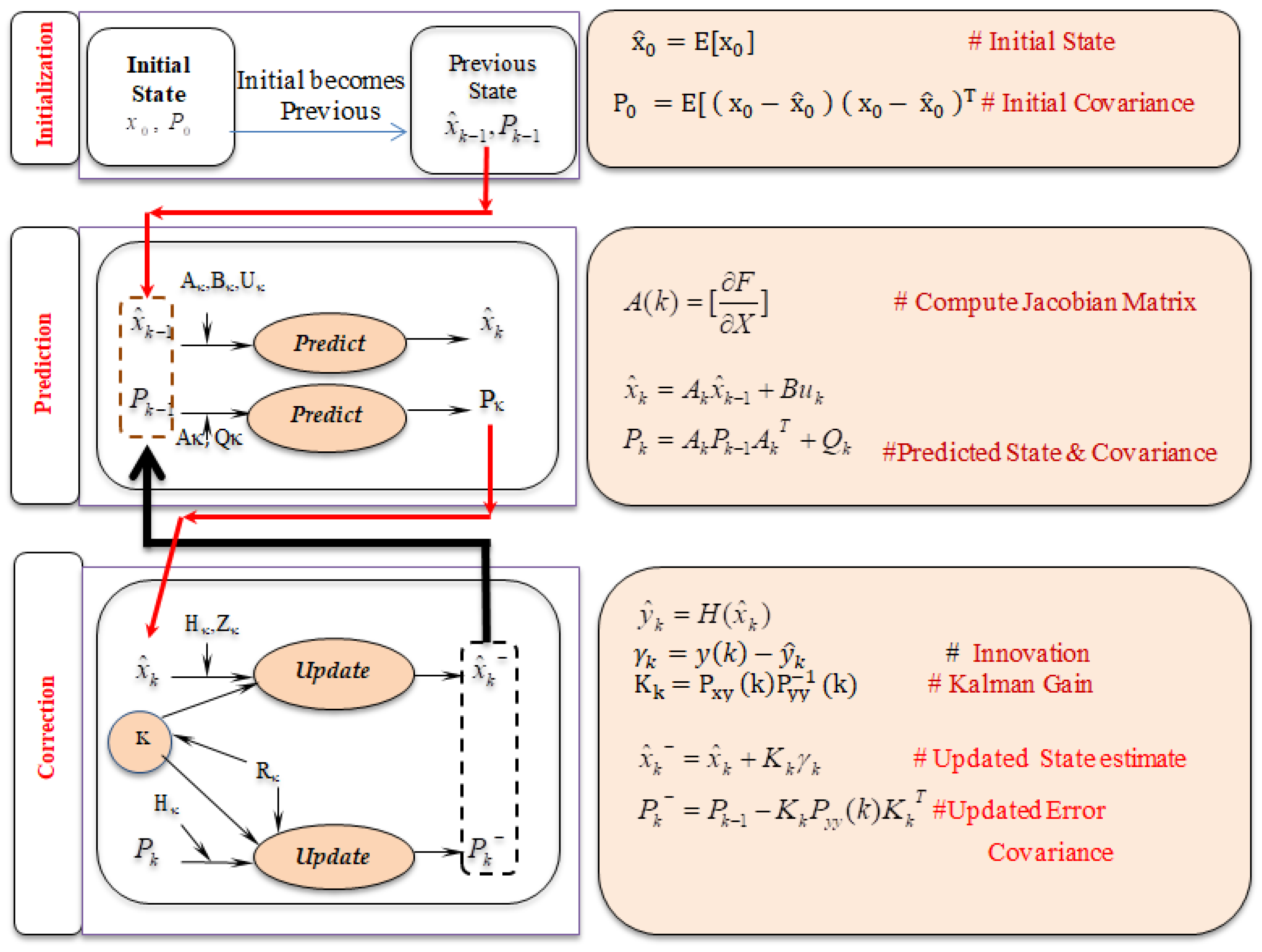
2.2.1. Extended Kalman Filter

The extended Kalman filter (EKF) is a recursive estimation method that expands upon the fundamental principles of the Kalman filter. Unlike its linear counterpart, the EKF is designed to accommodate non-linear systems by approximating them as linear around the current estimated state. This crucial adaptation allows the EKF to effectively estimate the true state of dynamic systems even in the presence of noisy measurements. At its core, the EKF operates through a state-space representation, capturing system dynamics in terms of first-order ordinary differential equations
The state vector x, control input u, system dynamics function f(x,u), and process noise Q constitute the components of this representation. Furthermore, the relationship between the state and measurements is encapsulated in the measurement equation z = h(x) + R, where h(x) characterizes the non-linear connection between the state and the measurements, and R signifies measurement noise.
The EKF algorithm unfolds through two primary steps: prediction and update. In the prediction step, the state estimate is projected ahead using the system dynamics, and the error covariance matrix is updated to account for process noise. This matrix involves the Jacobian matrix Fk and the process noise covariance matrix Qk. In the subsequent update step, the Kalman gain is computed, which involves the Jacobian matrix Hk and the measurement noise covariance matrix Rk. The state estimate is then adjusted using measurements, and the error covariance matrix is updated accordingly.
In this work, acquired voltage data are given as input and acquired current data are given as measurement, and the residual acquired with this measurement is updated to the next step. The Flowchart of Extended Kalman Filter is shown in Figure 2.

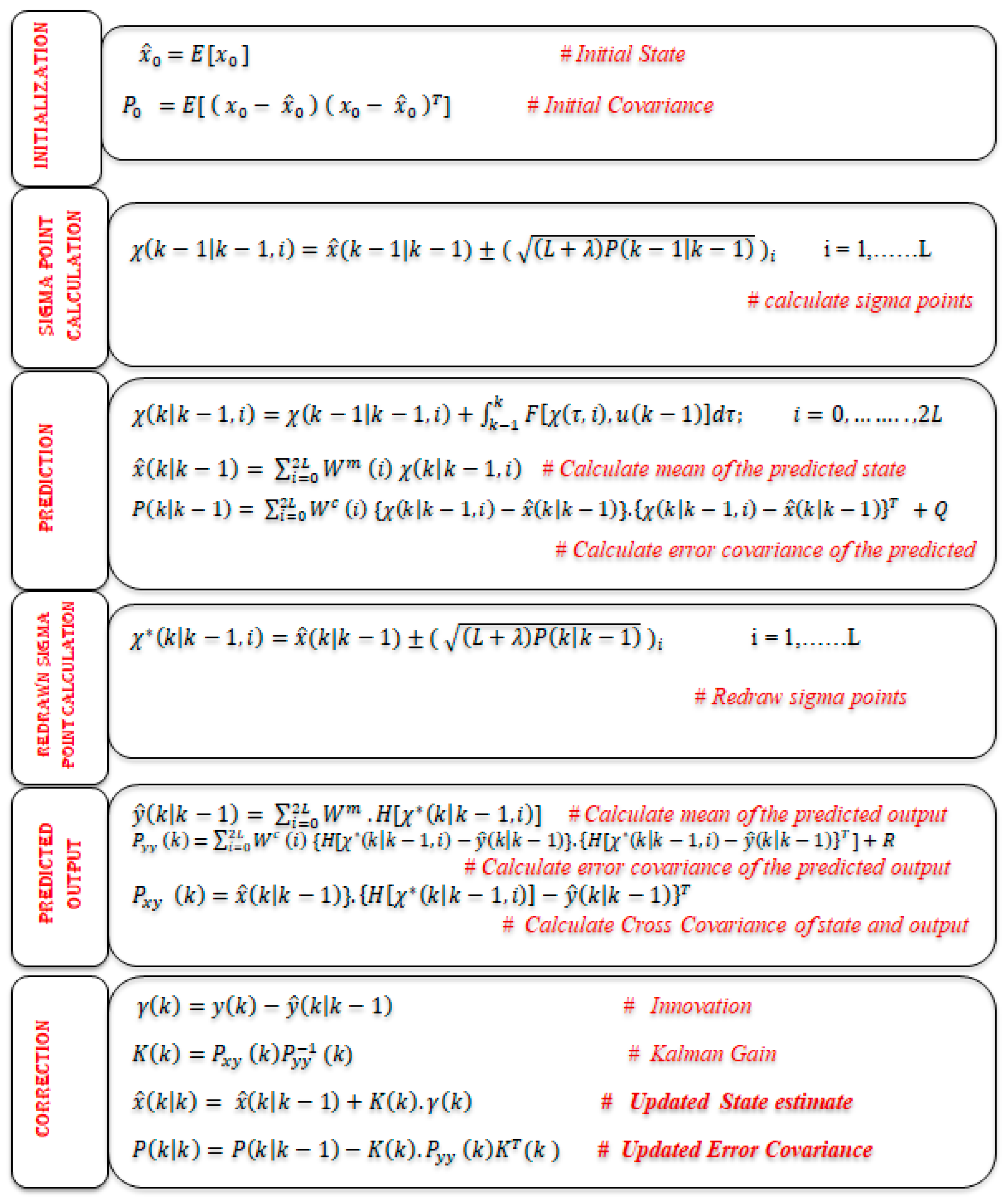
2.2.2. Unscented Kalman Filter

The unscented Kalman filter is an alternative to the extended Kalman filter (EKF) for handling non-linear systems. The UKF avoids the linearization step employed in the EKF, which can lead to inaccuracies in non-linear systems. Instead of linearizing the system dynamics and measurement functions, the UKF employs a deterministic sampling technique known as the “unscented transformation”. This technique effectively captures the mean and covariance of a set of carefully selected sigma points through non-linear transformations. These sigma points capture the distribution of the state space more accurately than linearized points used in the EKF. The equations involved in Unscented Kalman Filter is shown in Figure 3.
In the UKF, the filter’s performance was enhanced through the appropriate selection of scaling parameters α (alpha), β (beta), and κ (kappa) [21]. The spread of sigma points is illustrated in Figure 4. By calculating the square root of the sigma points’ covariance, we obtain the spread value. By adjusting the values of the scaling parameters, the distribution of sigma points varies, and its corresponding value is also determined. The scaling factors associated with the smallest obtained value are adopted for the UKF and DUKF algorithms. A subset of the scaling factors is presented in Figure 4. It can be inferred from Figure 4f that α = 0.1, β = 2, and κ = −3 yield the smallest value of 0.00027. Throughout this work, we utilized the values α = 0.1, β = 2, and κ = −3.

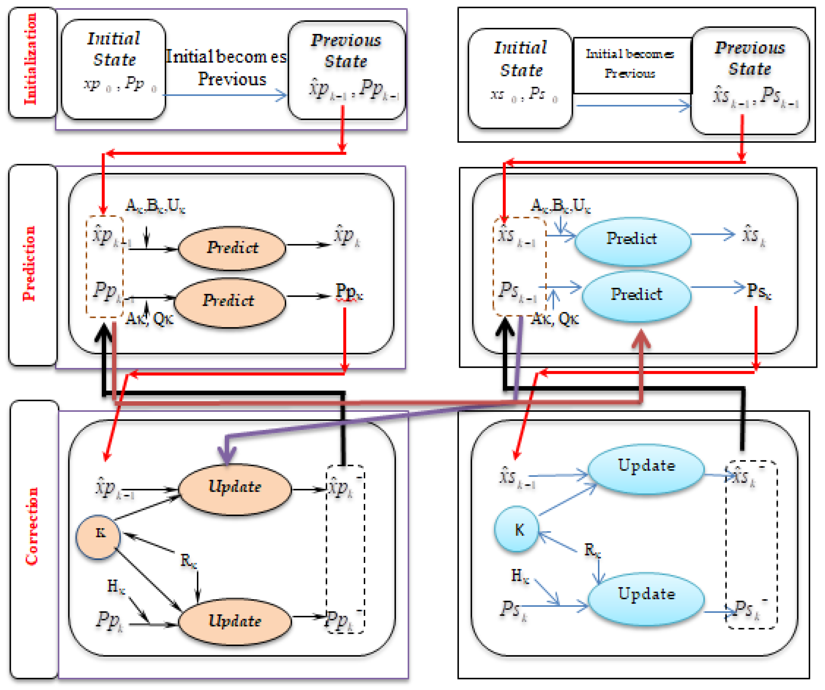
2.2.3. Dual Extended Kalman Filter

Dual nonlinear Kalman filters involve the simultaneous operation of two filters, wherein one is dedicated to estimating the state, and the other focuses on estimating parameters as shown in Figure 5. These filters operate concurrently to estimate both states and parameters from observational data. While the state filter treats parameters as constants, the parallel parameter filter considers states as known entities. The equations involved in Dual Extended Kalman Filter is as follows:
Parameter Prediction:State Prediction:
ρ ^ ( k | k 1 ) = ρ ^ ( k 1 | k 1 )
P ρ   ( k | k 1 ) = P ρ   ( k 1 | k 1 ) + Q ρ  
x ^ ( k | k 1 ) = x ^ ( k 1 | k 1 ) + k 1 k F x ( τ ) , ρ ^ ( k 1 | k 1 ) , u ( k 1 ) , d τ
P ( k | k 1 ) = Φ ( k ) P ( k 1 | k 1 ) Φ ( k ) T + Q
Parameter Update:State Update:
P y y ρ ( k ) = C ρ   ( k ) P ρ ( k | k 1 ) C ρ   ( k ) T + R ρ
C ρ ( k ) = { y ( k ) C ( k ) x ^ ( k | k 1 ) } ρ = C ( k ) x ^ ( k | k 1 ) ρ | ρ = ρ ^ ( k | k 1 )
K ρ   ( k ) = P x y ρ ( k | k 1 ) P y y ρ ( k ) 1
P x y ρ ( k | k 1 ) = P ρ ( k | k 1 ) C ρ   ( k ) T
ρ ^ ( k | k ) = ρ ^ ( k | k 1 ) + K ρ ( k ) y ( k ) H ρ x ^ ( k | k 1 ) , ρ ^ ( k | k 1 )
P ρ ( k | k ) = [ I K ρ   ( k ) C ρ   ( k ) ] P ρ ( k | k 1 )
y ^ ( k | k 1 ) = H x ^ ( k | k 1 )
γ ( k ) = y ( k ) y ^ ( k | k 1 )
P y y ( k ) = C ( k ) P ( k | k 1 ) C ( k ) T + R
C ( k ) = H x x ^ ( k | k 1 ) , ρ ( k | k 1 ) , u ( k 1 )
K ( k ) = P x y ( k ) P y y 1 ( k )
x ^ ( k | k ) = x ^ ( k | k 1 ) + K ( k ) γ ( k )
P ( k | k ) = I K ( k ) C ( k ) P ( k | k 1 )

2.2.4. Dual Unscented Kalman Filter

The equations involved in Dual Unscented Kalman Filter is as follows:
Parameter Prediction:State Prediction:
ρ ^ ( k | k 1 ) = ρ ^ ( k 1 | k 1 )
P ρ ( k | k 1 ) = P ρ ( k 1 | k 1 ) + Q ρ
x ^ ( k | k 1 ) = i = 0 2 L W m ( i ) χ ( k | k 1 , i )
P ( k | k 1 ) = i = 0 2 L W c ( i ) { χ ( k | k 1 , i ) x ^ ( k | k 1 ) } .                                                                             { χ ( k | k 1 , i ) x ^ ( k | k 1 ) } T + Q
Parameter Update:State Update:
y ^ ρ ( k | k 1 ) = i = 0 2 L ρ W m ( i ) . H ρ [ x ^ ( k | k 1 ) , χ ρ ( k | k 1 , i ) ]
P y y ρ ( k ) = i = 0 2 L ρ [ W c ( i ) { H ρ [ χ ρ ( k | k 1 , i ) ] y ^ ρ ( k | k 1 ) } .                                                                     { H ρ [ χ ρ ( k | k 1 , i ) ] y ^ ρ ( k | k 1 ) } T ] + R ρ
P xy ρ ( k ) = i = 0 2 L ρ W c ( i ) { χ ρ ( k | k 1 , i ) ρ ^ ( k | k 1 ) } .                                                                     { H ρ [ χ ρ ( k | k 1 , i ) ] y ^ ρ ( k | k 1 ) } T
γ ρ ( k ) = y ( k ) H ρ [ x ^ ( k | k 1 ) , ρ ^ ( k | k 1 ) ] K ρ ( k ) = P x y ρ ( k ) P y y ρ   1 ( k )
ρ ^ ( k | k ) = ρ ^ ( k | k 1 ) + K ρ ( k ) . γ ρ ( k )
P ρ ( k | k ) = P ρ ( k | k 1 ) K ρ ( k ) . P y y ρ ( k ) . K ρ T ( k )
y ^ ( k | k 1 ) = i = 0 2 L W m ( i ) . H [ χ * ( k | k 1 , i ) ]
P y y ( k ) = i = 0 2 L [ W c ( i ) { H [ χ * ( k | k 1 , i ) ] y ^ ( k | k 1 ) } .                                                                     { H [ χ * ( k | k 1 , i ) ] y ^ ( k | k 1 ) } T ] + R
P x y ( k ) = i = 0 2 L W c ( i ) { χ * ( k | k 1 , i ) x ^ ( k | k 1 ) } .                                                                 { H [ χ * ( k | k 1 , i ) ] y ^ ( k | k 1 ) } T
γ ( k ) = y ( k ) y ^ ( k | k 11 ) K ( k ) = P x y ( k ) P y y 1 ( k )
x ^ ( k | k ) = x ^ ( k | k 1 ) + K ( k ) . γ ( k )
P ( k | k ) = P ( k | k 1 ) K ( k ) . P y y ( k ) . K T ( k )

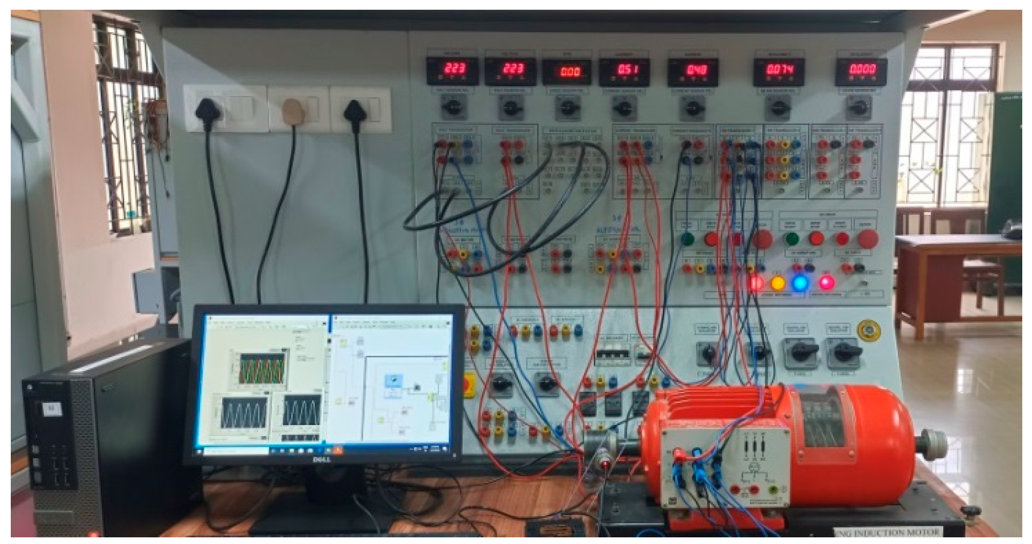
2.2.5. Real-Time Experimental Setup

The real-time experimental setup consists of a 1.0 kW WRIM connected to the DAQ USB-6351 for data acquisition, as illustrated in Figure 6. Approximately 5000 sampling instances of stator current and voltage data were collected from the WRIM under no-load conditions at a sampling rate of 1 ms using the NI USB-6351DAQ and LabVIEW 2018 software. The acquired voltage data are used as input for the extended Kalman filter, unscented Kalman filter, and their respective extensions for state estimation, while the acquired current data serve as measured values used for residuals. The four Kalman filters are estimated offline with the assistance of MATLAB R2021a software. The assumptions made throughout the analysis are presented in Table 3.
The acquired voltage data and current data at a sampling rate of 1 ms are shown in Figure 7 and Figure 8, respectively.
The estimators employed in this study include the EKF, UKF, DEKF, and DUKF. The real-time acquired current data is treated as the residual measured current. During the filter evaluation process, noise covariance values P and Q were determined through a trial-and-error approach to achieve optimal estimation, and the measured noise R was quantified using the uncertainty formula as presented in Equation (3), derived from the collected real-time data.
U n c e r t a i n i t y =   s u m x i m e a n   2 / n × 1 n 1
where x i r e a d i n g s , n-no of readings in the dataset.
Motor speed and rotor resistance (Rr) are chosen as the reference states for evaluating the filter performance. The average value of the calculated mean squared error (MSE) for each instance is employed as a performance metric. Throughout the analysis, the values in Table 3 are assumed for all the filters.

3. Results and Discussion

Motor speed and Rr are estimated by all four Kalman filters. To assess the effectiveness of these filters, various analyses are conducted on their estimates under different operating conditions, namely healthy and asymmetry cases.
The following analyses were conducted:
  • State estimation
  • State estimation with different initial conditions
  • Analytical solution of the model
  • Parameter sensitivity analysis
  • Kurtosis

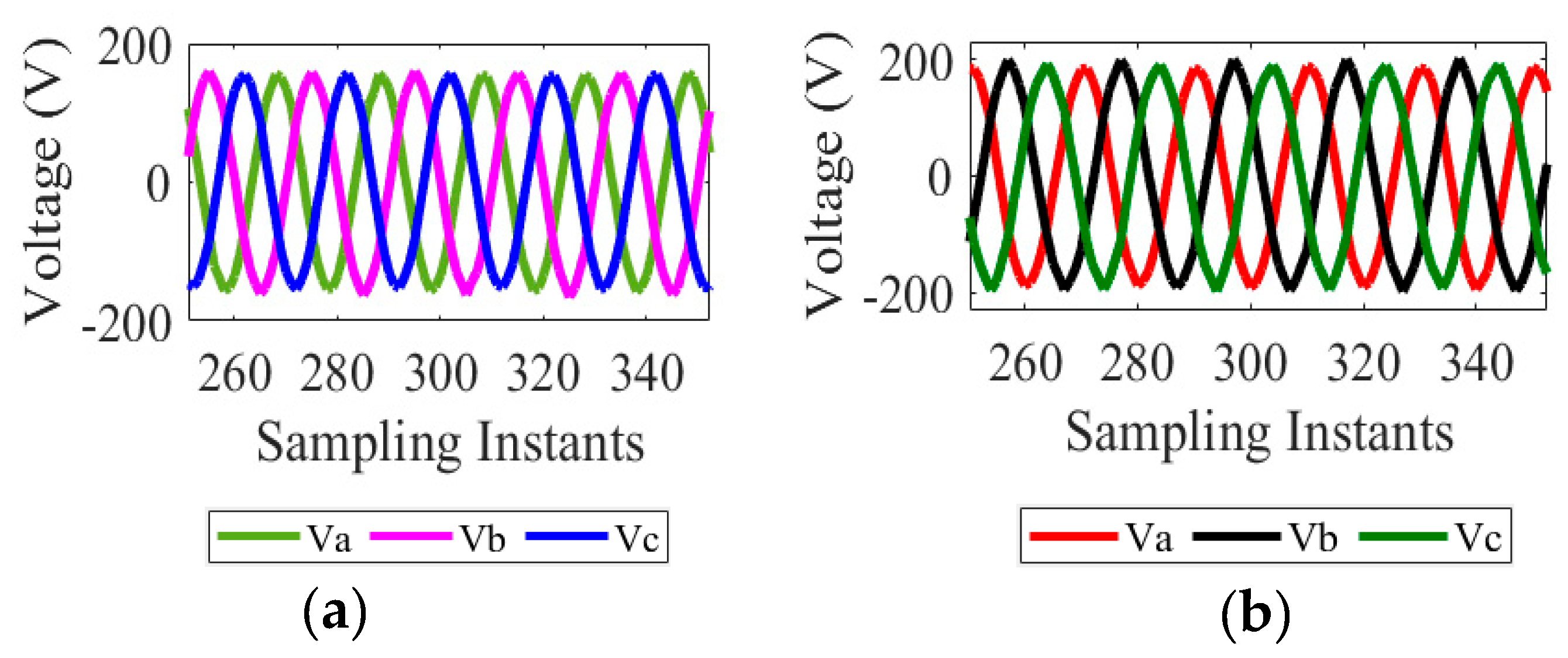
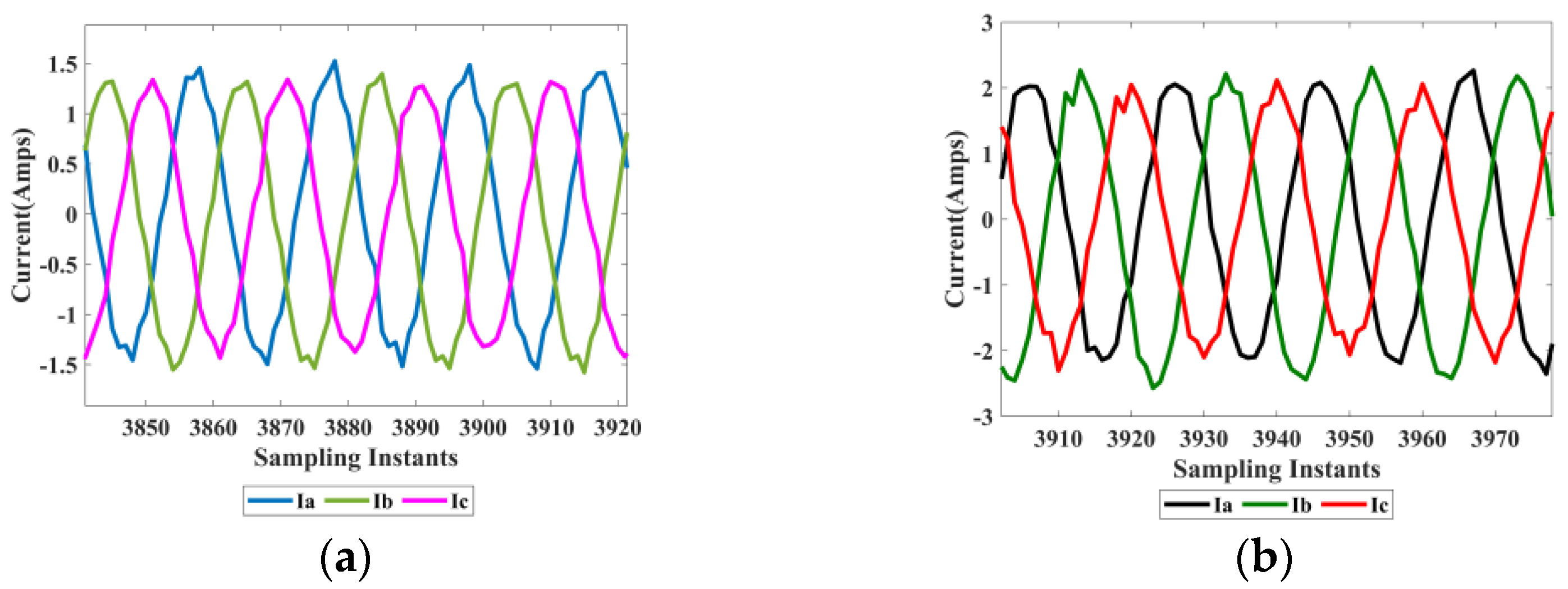
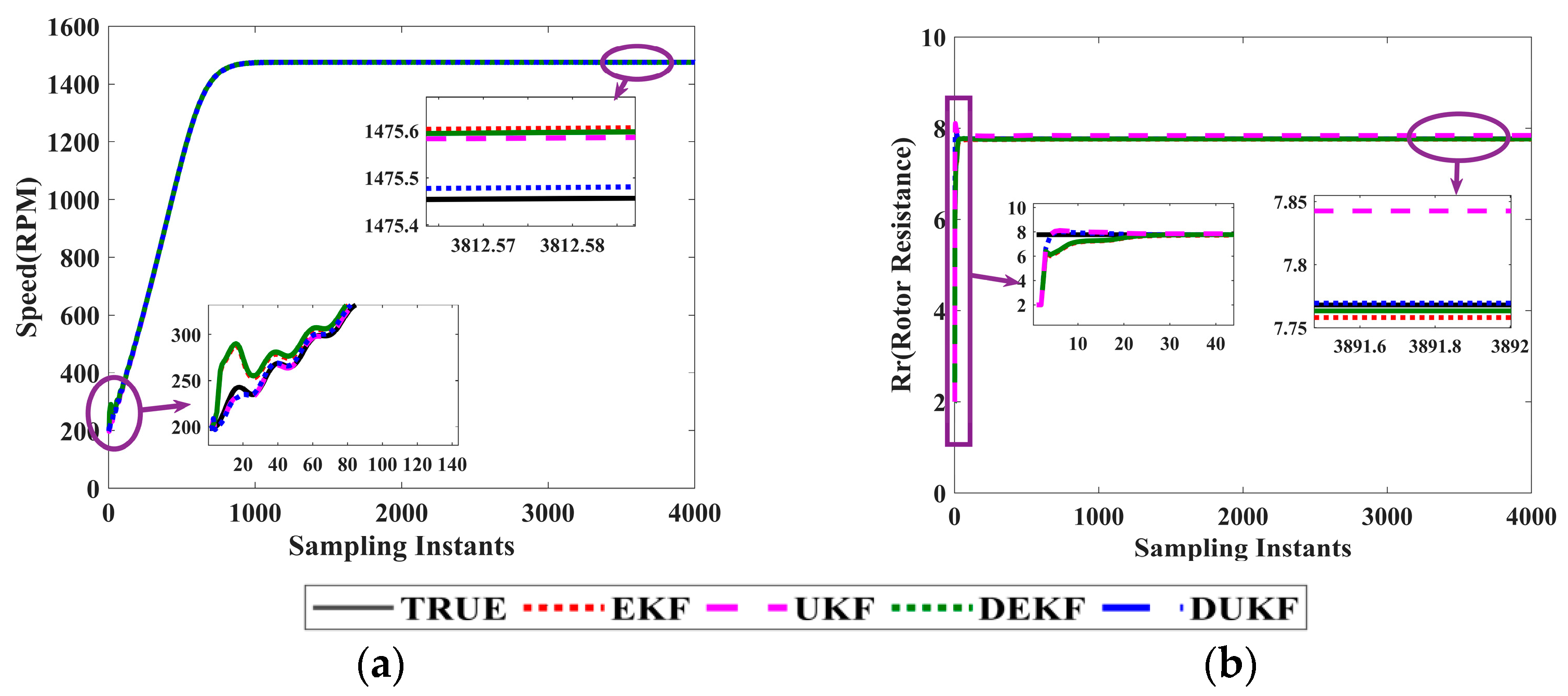
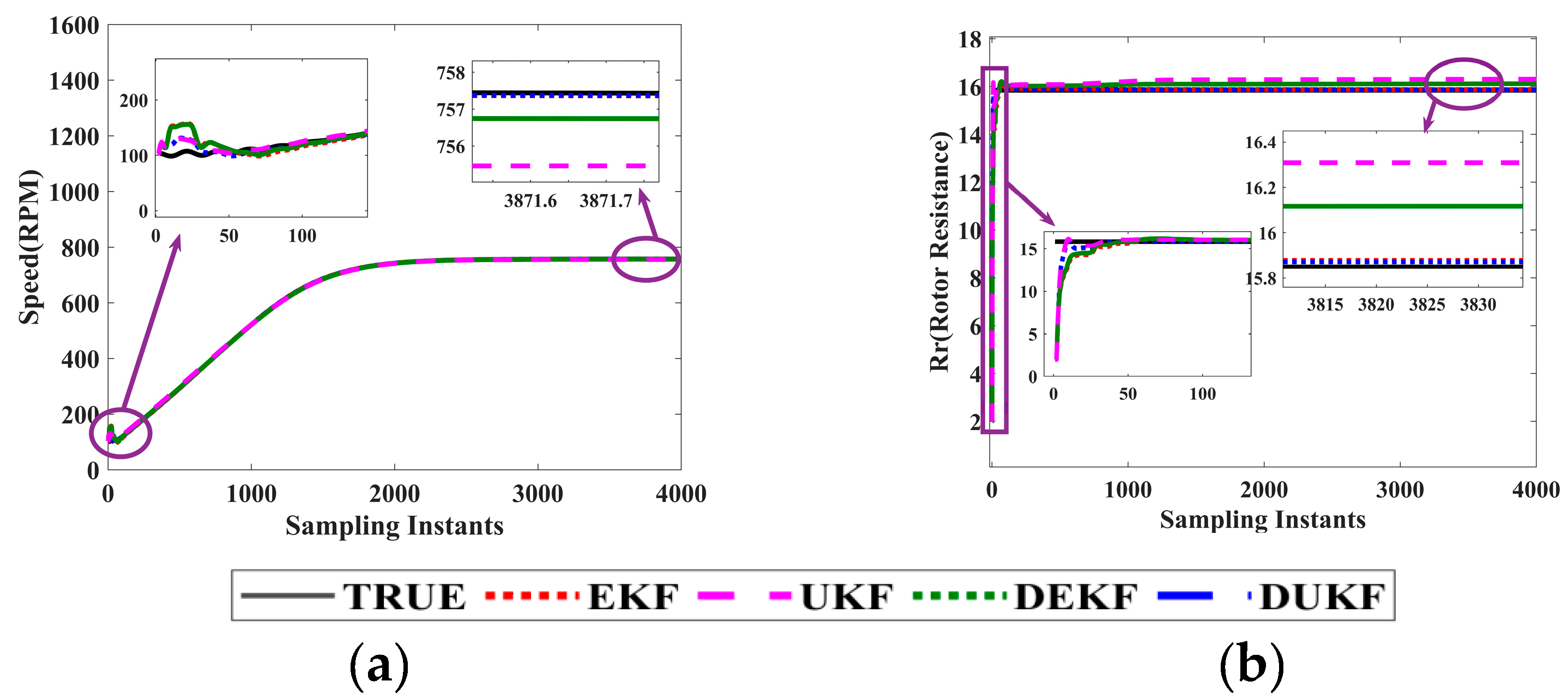
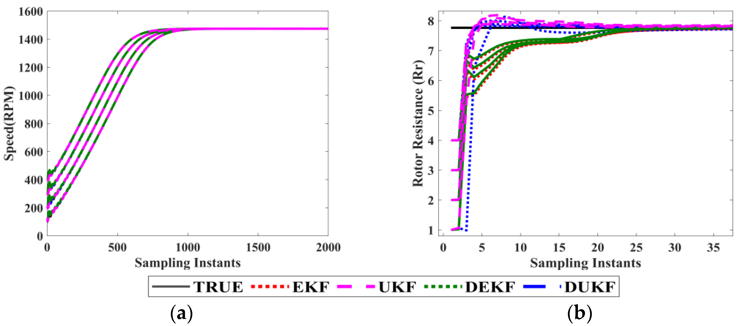
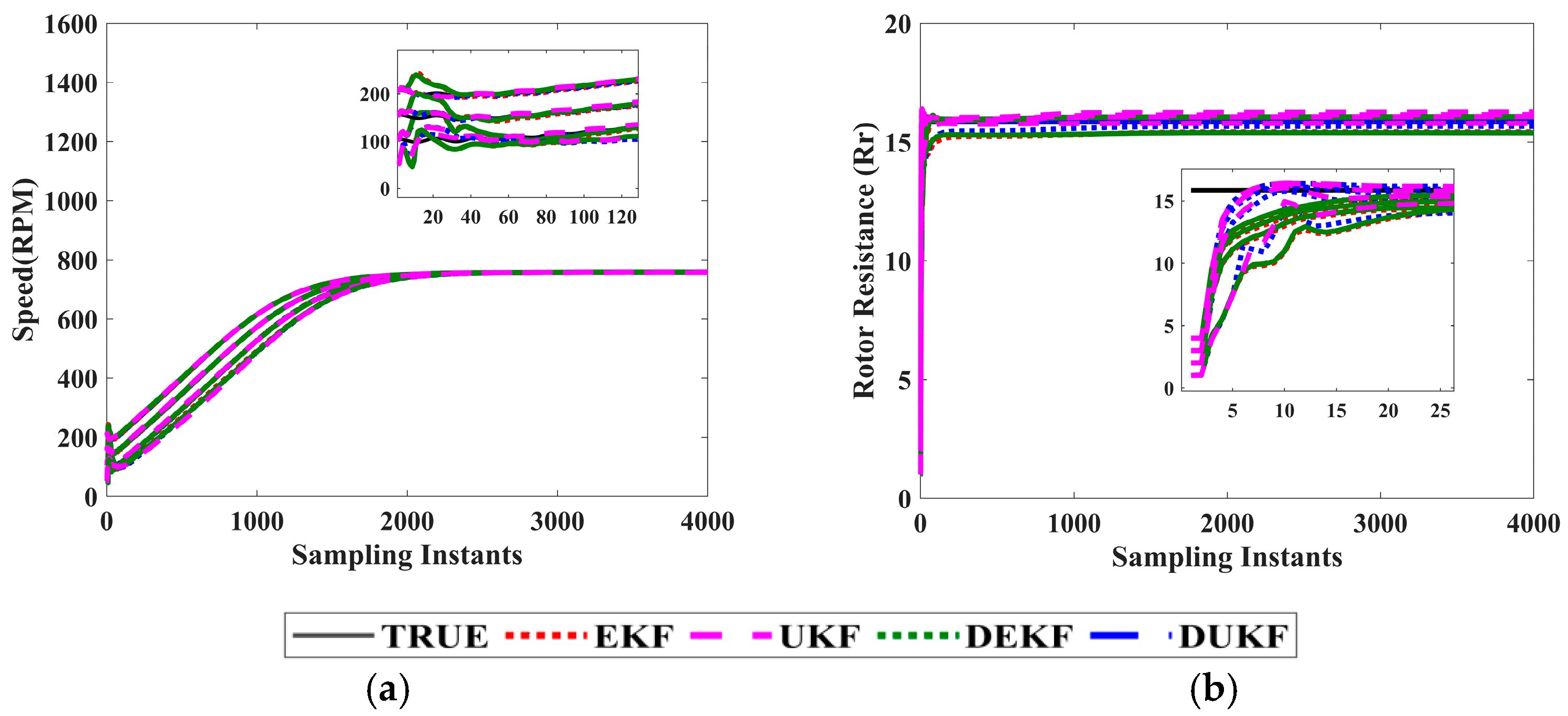
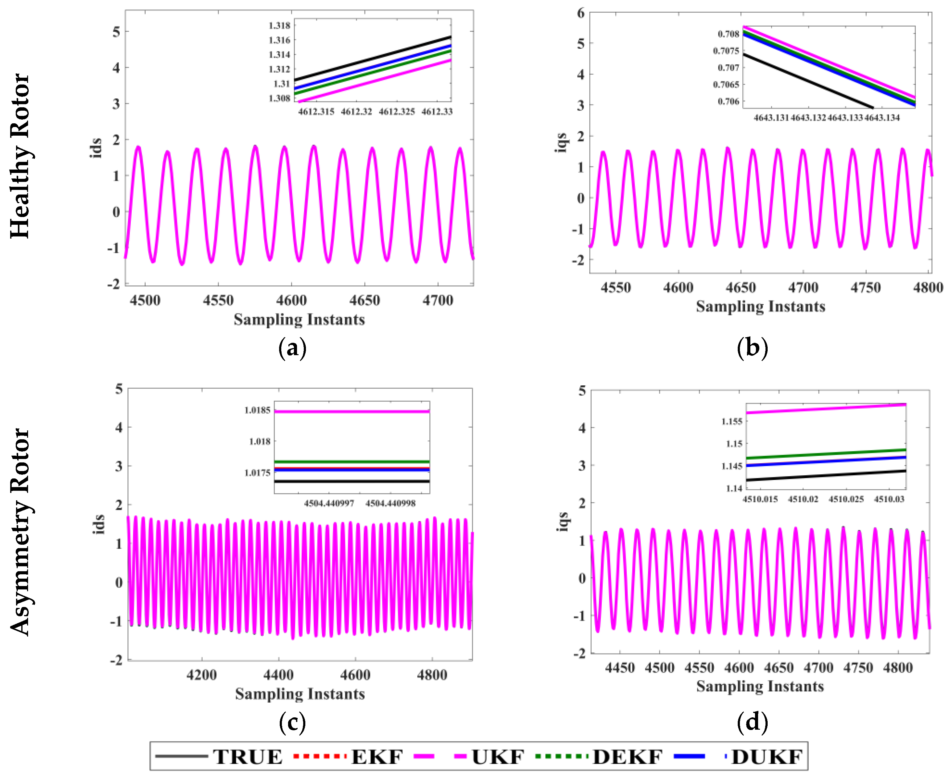
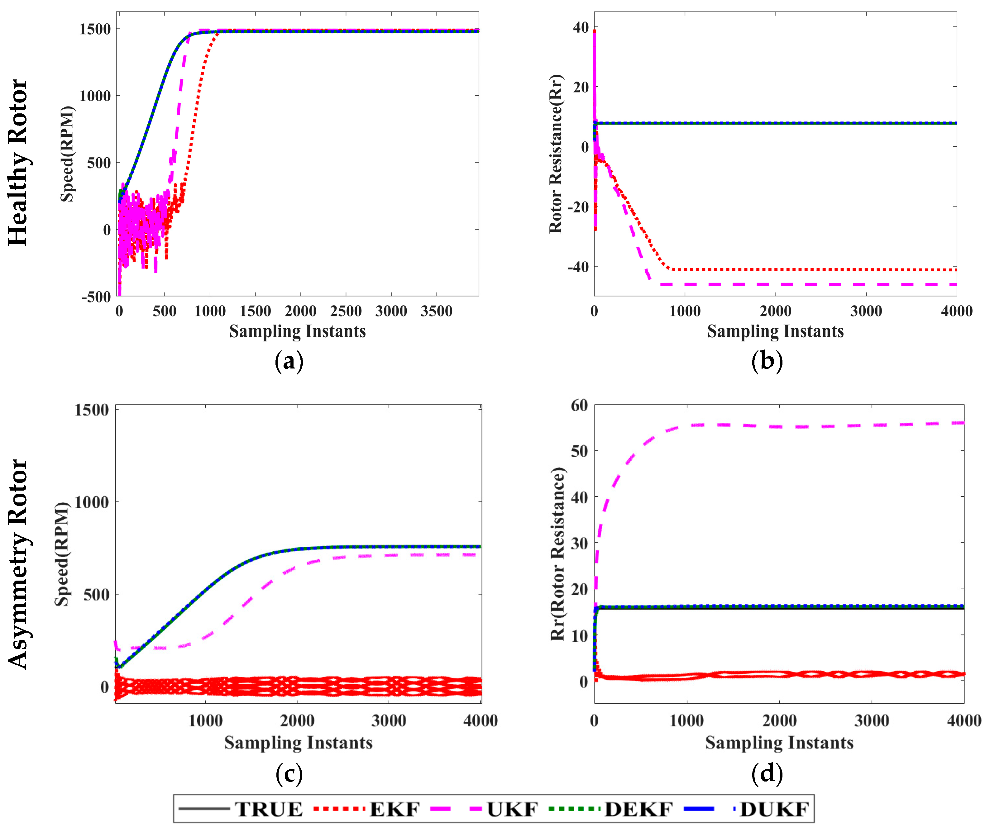
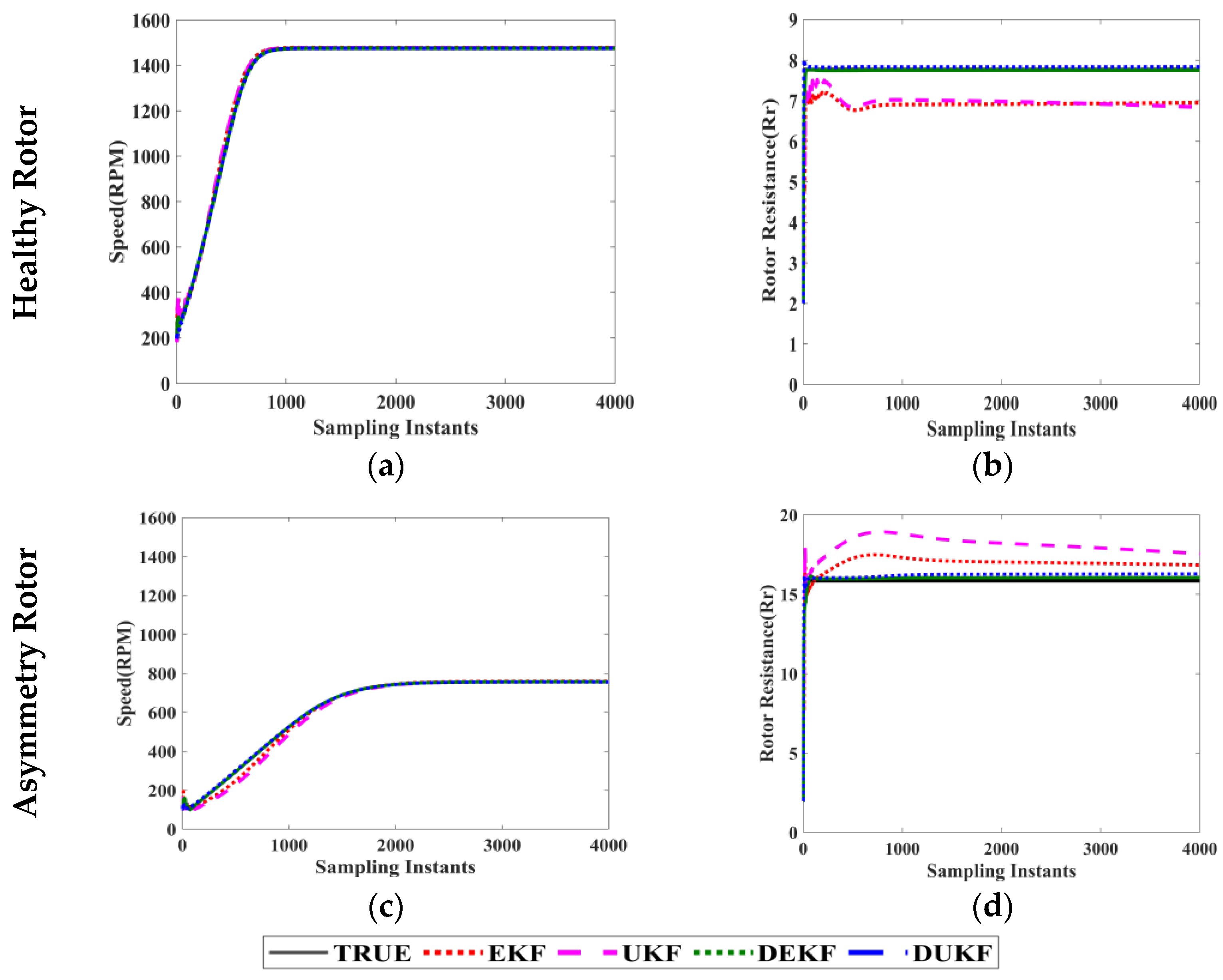
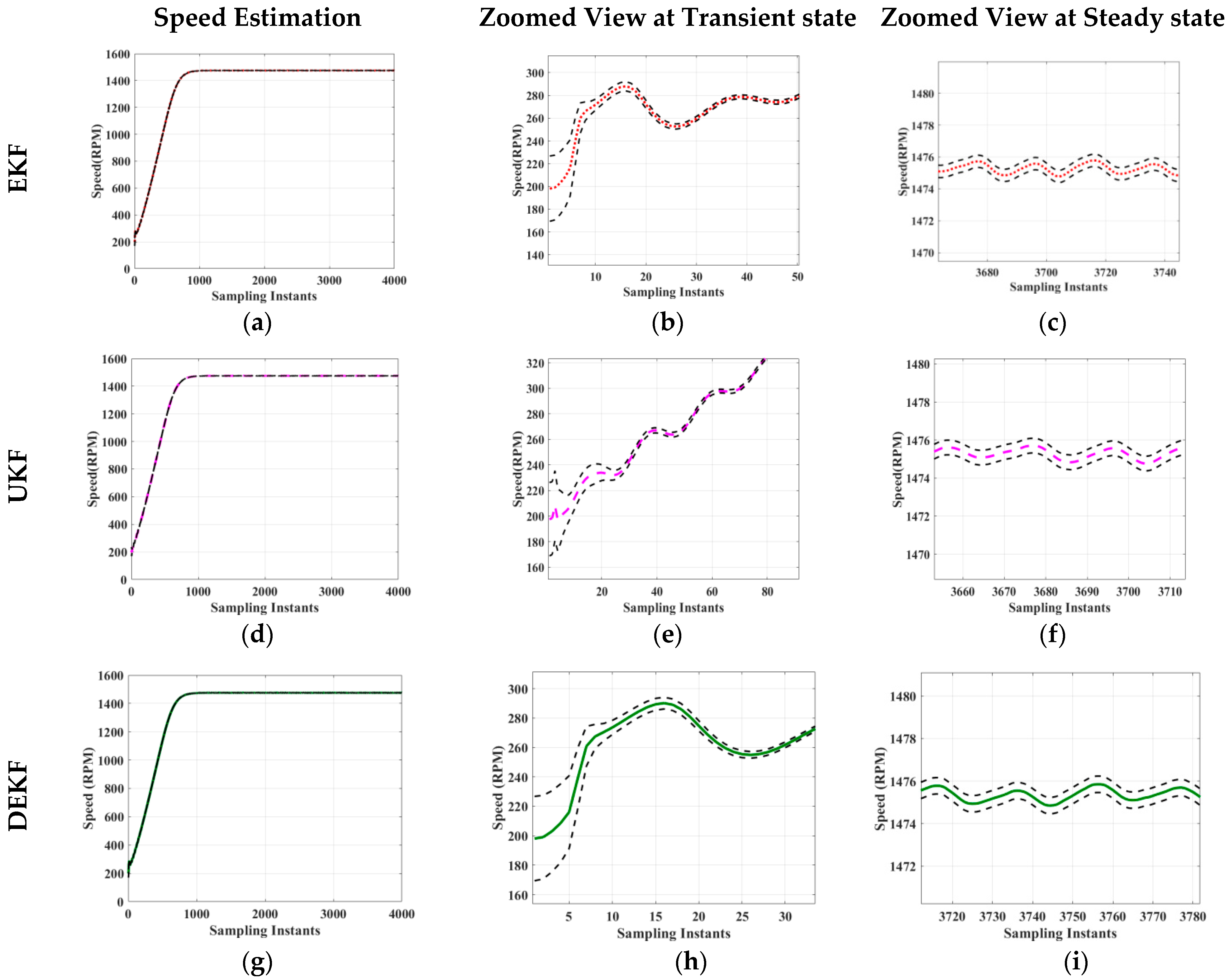
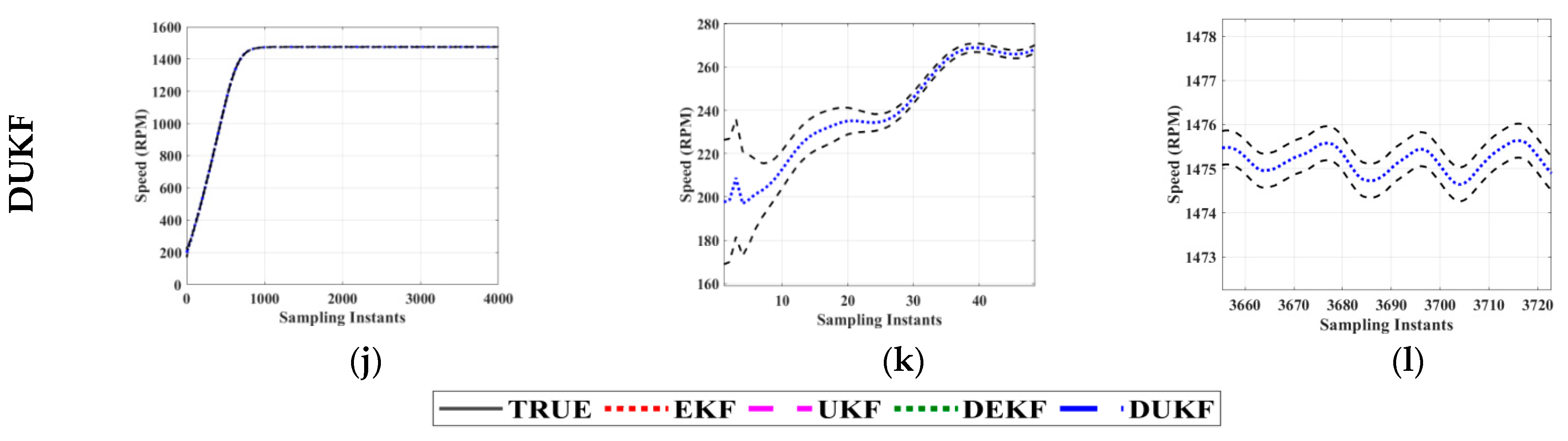
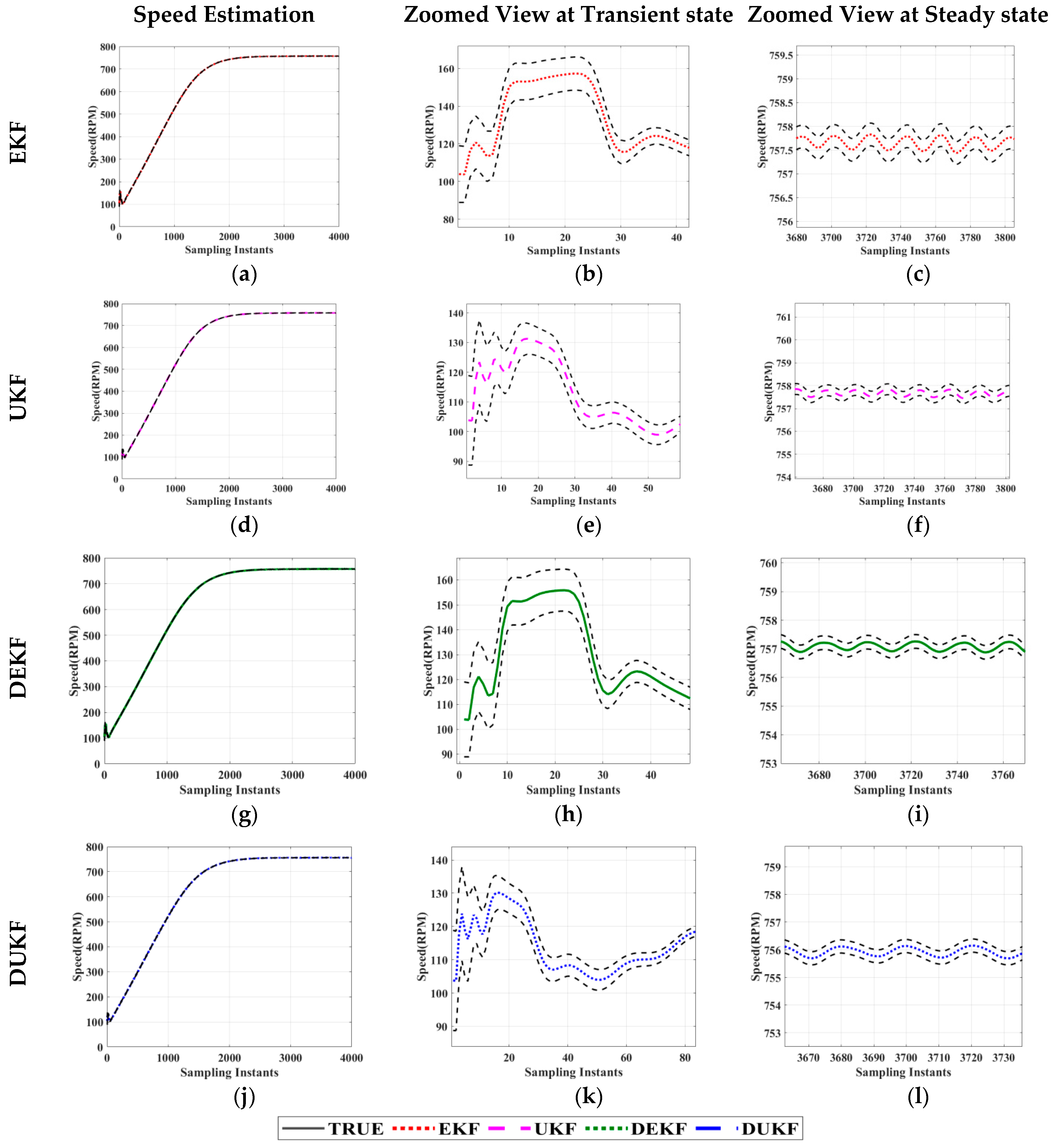
3.1. State Estimation

In this analysis, acquired voltage and current data were utilized. The calculated parameter values for the measured speed are 1475 rpm, and calculated rotor resistance is 7.768 ohms. Similarly, in the asymmetry rotor condition, where terminals K-M are shorted, the measured speed is 757 rpm, and the calculated rotor resistance is 15.85 ohms. Using acquired voltage data as input and acquired current data as residual, speed and rotor resistance values are obtained from different variants of the Kalman filter.
The initial conditions employed to estimate these states for both healthy and asymmetry rotor cases are set as {1.5; 1; 0.4; 0.3; 200 × (2 × pi/60); 0; 2}. The filter estimates for both healthy and asymmetry rotor conditions are illustrated in Figure 9 and Figure 10, respectively.
Based on observations from Figure 9a,b and findings provided in Table 4, it can be inferred that in the scenario of a healthy rotor condition, specific behaviors are noticeable.
During the initial transient state, both UKF and DUKF provided minor biases in their speed and rotor resistance estimates. As the system reached a stable state, EKF provided a bias of +0.15% for speed estimation, while UKF and DEKF demonstrated biases of +0.14% and +0.145%, respectively. For DUKF, a minimal bias of +0.03% was observed in speed estimation.
In terms of rotor resistance estimation, EKF provided a bias of −0.01%, UKF presented a bias of +0.074%, DEKF displayed a bias of −0.0045%, and DUKF revealed a bias of +0.0015%. Considering both speed and rotor resistance estimation, it is evident that DUKF provided the least biased estimates.
From Figure 10a,b and Table 5, in the case of an asymmetry condition, it is observed that during the initial transient state, all filters exhibit biases away from the true values.
For speed estimation, EKF provided a −0.01% bias, UKF provided a −1.78% bias, DEKF provided a −0.63% bias, and DUKF presented a +0.001% bias.
For rotor resistance estimation, EKF provided a +0.03% bias, UKF provided a +0.45% bias, DEKF provided a +0.25% bias, and DUKF presented a +0.02% bias. In both estimation scenarios, DUKF consistently provided the least biased estimates.

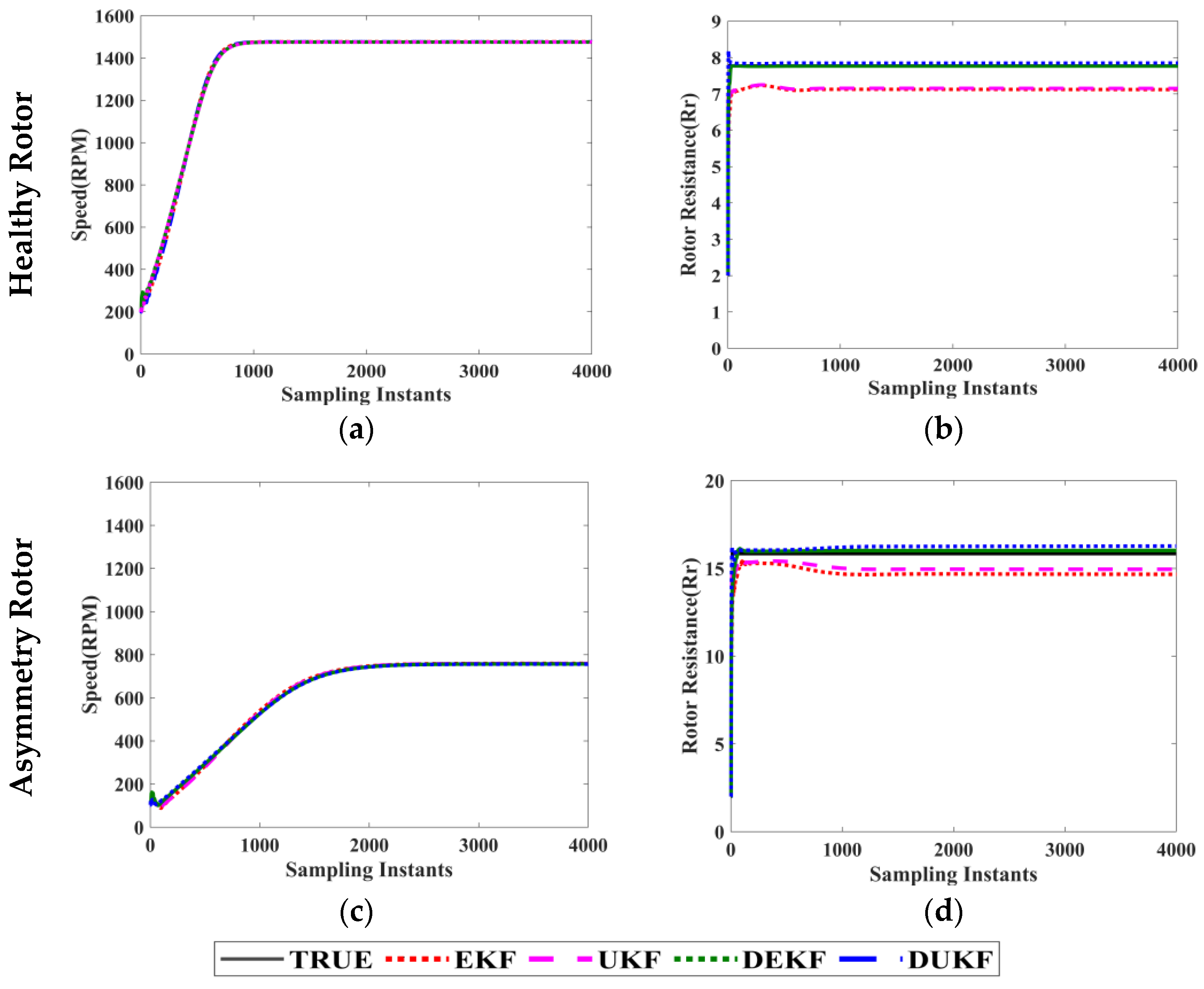
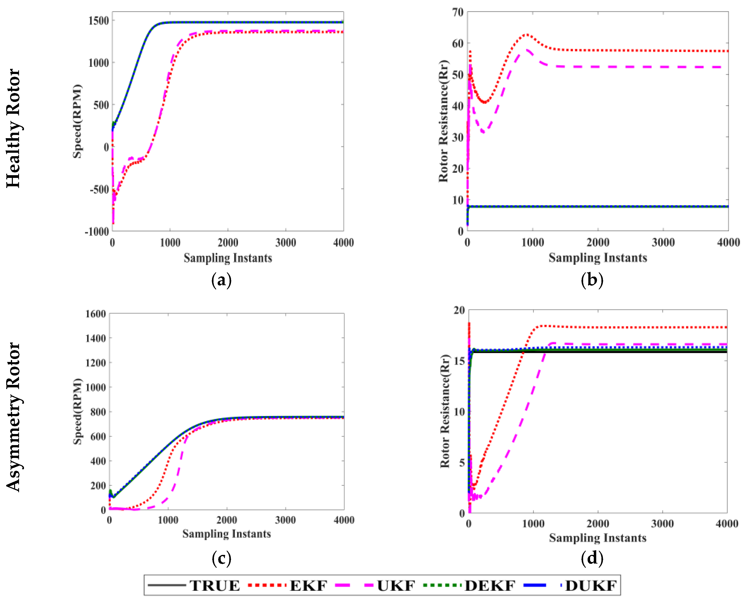
3.2. State Estimation with Different Initial Conditions

In this analysis, the states of speed and rotor resistance for healthy rotor data and asymmetry rotor data are estimated under different initial conditions for both speed and rotor resistance. These initial conditions include speeds of 100, 200, 300, and 400, each paired with corresponding resistances of 1, 2, 3, and 4.
The utilized initial conditions are as follows: {1.5; 1; 0.4; 0.3; 100 × (2 × pi/60); 0; 1}, {1.5; 1; 0.4; 0.3; 200 × (2 × pi)/60); 0; 2},{1.5; 1; 0.4; 0.3; 300 × (2 × pi)/60); 0; 3},{1.5; 1; 0.4; 0.3; 400 × (2 × pi)/60); 0;4}.
From Figure 11a,b, using all initial conditions, speed and rotor resistance are estimated and the steady state remains the same.
Figure 12a,b demonstrate the estimation of speed and rotor resistance using all initial conditions, and the steady state remains the same.
Notably, when estimating states with various initial conditions, the resulting estimates converge to the same values. Among all the filters, DUKF consistently yields the least biased estimates.
Inference 1:
The inference from the above analysis has two aspects:
  • Based on the acquired voltage and current data and the estimation of both states for both the healthy and asymmetry rotor, it is inferred that DUKF is robust and outperforms all other filter estimates.
  • All filter estimates remain consistent across various initial conditions.

3.3. Analytical Solution

The analytical solution of model ids and iqs measured and estimated results are shown below.
Figure 13a,b show the output ids and iqs for the healthy rotor, displaying both measured and estimated currents.
Similarly, Figure 13c,d present the output ids and iqs for the asymmetry rotor, with both measured and estimated currents.

3.4. Parameter Sensitivity Analysis

The parameter sensitivity analysis enables the study of how parameters are sensitive towards the estimated states when parameters are increased or decreased. In this work, we are estimating rotor resistance as one of the states. Therefore, remaining parameters such as stator resistance, stator inductance, rotor inductance, and mutual inductance are considered for analysis.
In this analysis, we increased the stator resistances to 10%, decreased the stator and rotor inductances to 10%, reduced mutual inductance to 10%, and explored the effects of increasing resistances while decreasing all inductances on how the estimates respond. The range of variation is calculated by subtracting maximum-minimum.
The results of the parameter sensitivity analysis are presented for both healthy and asymmetry conditions, considering a parameter mismatch of a 10% increase in stator resistance, as shown in Figure 14.
From Figure 14a, for speed estimation in the healthy condition, EKF provided a +1.13% bias, DUKF provided a −0.01% bias, DEKF provided a +0.1% bias, and UKF provided a +1.075% biased estimate. The range of variation is 1.14. From Figure 14b, regarding rotor resistance estimation under healthy conditions, EKF provided a −0.65% bias, UKF provided a −0.615% bias, DEKF provided a +0.005% bias, and DUKF provided a +0.07% biased estimate. The range of variation is 0.72.
In Figure 14c, in the case of speed estimation under asymmetry conditions, EKF provided a +1.9% bias, UKF provided a +1.6% bias, DEKF provided a −0.61% bias, and DUKF provided a −1.6% biased estimate. The range of variation is 2.51. Finally, in Figure 14d, for rotor resistance estimation in the asymmetry condition, EKF provided a −1.1% bias, UKF provided a −0.9% bias, DEKF provided a +0.25% bias, and DUKF provided a +0.45% biased estimate. The range of variation is 1.55. However, in both cases, the dual filters provided lower biased estimates.
The results of the parameter sensitivity analysis are presented for both healthy and asymmetry conditions, considering a parameter mismatch of a 10% decrease in stator and rotor inductance, as shown in Figure 15.
From Figure 15a, for speed estimation in the healthy condition, EKF and UKF provided a −9.86% bias, DEKF provided a -0.04% bias, and DUKF provided a +0.09% biased estimate. The range of variation is 9.95. In Figure 15b, for rotor resistance estimation in the healthy condition, EKF provided a −32.232% bias, UKF provided a −37.232% bias, DEKF provided a +0.005% bias, and DUKF provided a +0.072% biased estimate. The range of variation is 37.304.
In Figure 15c, for speed estimation in the asymmetry condition, EKF failed to estimate, UKF provided a −45% bias, DEKF provided a −0.5% bias, and DUKF provided a −1.5% biased estimate. The range of variation is 44.5. Finally, in Figure 15d, for rotor resistance estimation in the asymmetry condition, EKF failed to estimate, UKF provided a +40.85% bias, DEKF provided a +0.25% bias, and DUKF provided a +0.45% biased estimate. The range of variation is 40.6. However, in both conditions, dual filters proved to be robust and provided low biased estimates.
The results of the parameter sensitivity analysis are presented for both healthy and asymmetry conditions, considering a parameter mismatch of 10% decrease in mutual inductance, as shown in Figure 16.
From Figure 16a, speed estimation in the healthy condition, EKF provided a −115.12% bias, UKF provided a −105.12% bias, DEKF provided a +0.06% bias, and DUKF provided a +0.07% biased estimate. The range of variation is 115.27. From Figure 16b, regarding rotor resistance estimation in the healthy condition, EKF provided a +50.232% bias, UKF provided a +46.232% bias, DEKF provided a −0.005% bias, and DUKF provided a +0.072% biased estimate. The range of variation is 50.237.
In Figure 16c, in the case of speed estimation under asymmetry conditions, EKF provided a −9.5% bias, UKF provided a −8.3% bias, DEKF provided a −0.95% bias, and DUKF provided a −2% biased estimate. The range of variation is 8.55. Finally, in Figure 16d, For the rotor resistance estimation in the asymmetry condition, EKF provided a +2.3% bias, UKF provided a +1.6% bias, DEKF provided a +0.25% bias, and DUKF provided a +0.45% biased estimate. The range of variation is 2.05. However, in both conditions, dual filters are robust and provide low biased estimates.
The results of the parameter sensitivity analysis are presented for both healthy and asymmetry conditions, considering a parameter mismatch of 10% increase in resistances and 10% decrease in inductances, as shown in Figure 17.
From Figure 17a, speed estimation in the healthy condition, EKF provided a −2.69% bias, UKF provided a −2.25% bias, DEKF provided a −0.1% bias, and DUKF provided a +0.03% of biased estimate. The range of variation is 2.72. From Figure 17b, regarding rotor resistance estimation in the healthy condition, EKF provided a +0.838% bias, UKF provided a +0.938% bias, DEKF provided a +0.005% bias, and DUKF provided a −0.072% of biased estimate. The range of variation is 1.01.
In Figure 17c, in the case of speed estimation under asymmetry conditions, EKF provided a +1.65% bias, UKF provided a −0.15% bias, DEKF provided a −0.55% bias, and DUKF provided a −1.65% of biased estimate. The range of variation is 3.3. Finally, in Figure 17d, for rotor resistance estimation in the asymmetry condition, EKF provided a +1.15% bias, UKF provided a +2.05% bias, DEKF provided a +0.25% bias, and DUKF provided a +0.45% of biased estimate. The range of variation is 1.8. However, in both conditions, dual filters are robust and provide low biased estimates.
Inference 2:
The inferences from parameter sensitivity analysis are threefold:
  • From Table 6, an observed low bias in the filter estimates occurs when the parameter Rs is mismatched. A medium bias is present in the filter estimate when the parameter Lm is mismatched, and the estimates exhibit a high bias when Ls and Lr are mismatched. Therefore, the stator resistance has low sensitivity, the mutual inductance has medium sensitivity, and stator and rotor inductances are highly sensitive to the state estimation.
  • Even in the presence of parameter mismatches, dual filters remain robust in estimating speed and rotor resistance.
  • Since dual filters offer a slightly biased estimate, they are proposed as effective soft sensors for reducing false alarms.

3.5. Kurtosis

The designed filter estimators, namely EKF, UKF, DEKF, and DUKF, are validated using the confidence level test of kurtosis. In this context, an interval of x ^ ± 3 s i g m a is applied to all speed estimates to determine whether the estimates converge within the 99.73% confidence interval. Each speed estimation is obtained between x ^ + 3 s i g m a and x ^ 3 s i g m a , which validates their convergence.
The attainment of the fourth-order moment (kurtosis) by the designed filter estimators for healthy and asymmetrical rotor conditions is shown in Figure 18 and Figure 19, respectively. Zoomed figures for each filter estimation, depicting both the transient and steady states, are shown in Figure 18 and Figure 19.
Figure 18 and Figure 19 indicate that the speed state estimates obtained by the filter under both healthy and asymmetrical conditions converge within the confidence interval. Thus, the convergence test validates the accuracy of the designed Kalman filters.

4. Conclusions

This paper presents the detection of rotor asymmetry faults in wound rotor induction motors (WRIM) using EKF, UKF, DEKF, and DUKF filters. Both healthy and asymmetric rotor fault real-time data were gathered from an experimental setup of WRIM. Motor parameters were calculated through standard tests. Since asymmetry faults are identified as changes in rotor resistance, which, in addition, influences speed, both Rr and speed are estimated. The results of state estimation are discussed under various operating conditions, including healthy and asymmetric cases. An extensive analysis of healthy and rotor asymmetric fault detection, the robustness of different variants of Kalman filters, filter sensitivity to parameter variations, and filter convergence were conducted.
From the results, it was observed that for detecting healthy and asymmetric conditions, DUKF provided better performance for both speed and rotor resistance estimation. Additionally, it can be concluded from parameter sensitivity analysis, dual filters were robust in both healthy and asymmetric cases, and the results revealed that Rs has low sensitivity, Lm has medium sensitivity, and stator and rotor inductances (Ls, Lr) are highly sensitive to all mismatch conditions. This analysis also led to the conclusion that, under all the aforementioned sensitivity conditions, dual filters provide low-biased estimates and can be proposed as effective variants of the Kalman filter to prevent false alarms.

Author Contributions

Conceptualization, F.J.B.; Methodology, F.J.B.; Software, F.J.B.; Validation, F.J.B.; Formal Analysis, F.J.B.; Investigation, F.J.B.; Resources, F.J.B.; Data Curation, F.J.B.; Writing—Original Draft Preparation, F.J.B.; Writing—Review and Editing, F.J.B. and K.S.; Visualization, F.J.B.; Supervision, K.S.; Project Administration, K.S. All authors have read and agreed to the published version of the manuscript.

Funding

This research received no external funding.

Data Availability Statement

The data presented in this study are available on request from the corresponding author. The data is not publicly available due to working on another paper.

Conflicts of Interest

The authors declare no conflict of interest.

Nomenclature

WRIMWound Rotor Induction Motor
SCIMSquirrel Cage Induction Motor
DFIGDoubly Fed Induction Generator
EKFExtended Kalman Filter
UKFUnscented Kalman Filter
DEKFDual Extended Kalman Filter
DUKFDual Unscented Kalman Filter
RAFRotor Asymmetry Fault
SAFStator Asymmetry Fault
FDDFault Detection and Diagnosis
MCSAMotor Current Signature Analysis
IDFTIterative localized Discrete Fourier Transform
CWTContinuous Wavelet Transform
SCSVMStator Current Space Vector Magnitude
IMSCInstantaneous Magnitude of the Stator Current
RsStator Resistance
RrRotor Resistance
LsStator Inductance
LrRotor Inductance
LmMutual Inductance

References

  1. Bebars, A.D.; Eladl, A.A.; Abdulsalam, G.M.; Badran, E.A. Internal electrical fault detection techniques in DFIG-based wind turbines: A review. Prot. Control Mod. Power Syst. 2022, 7, 18. [Google Scholar] [CrossRef]
  2. Ameid, T.; Menacer, A.; Talhaoui, H.; Harzelli, I. Rotor resistance estimation using Extended Kalman filter and spectral analysis for rotor bar fault diagnosis of sensorless vector control induction motor. Measurement 2017, 111, 243–259. [Google Scholar] [CrossRef]
  3. Ferrucho-Alvarez, R.E.; Martinez-Herrera, A.L.; Cabal-Yepez, E.; Rodriguez-Donate, C.; Lopez-Ramirez, M.; Mata-Chavez, R.I. Broken rotor bar detection in induction motors through contrast estimation. Sensors 2021, 21, 7446. [Google Scholar] [CrossRef] [PubMed]
  4. Farzaneh, K.; Poshtan, J.; Poshtan, M. Detection of broken rotor bars in induction motors using nonlinear Kalman filters. ISA Trans. 2010, 49, 189–195. [Google Scholar]
  5. Yetgin, A.G. Effects of induction motor end ring faults on motor performance. Experimental results. Eng. Fail. Anal. 2019, 96, 374–383. [Google Scholar] [CrossRef]
  6. Kia, S.H. Detection of Stator and Rotor Asymmetries Faults in Wound Rotor Induction Machines: Modeling, Test and Real-Time Implementation. In Emerging Electric Machines-Advances, Perspectives and Applications; IntechOpen: London, UK, 2021. [Google Scholar]
  7. Vedreño-Santos; Francisco; Riera-Guasp, M.; Henao, H.; Pineda-Sánchez, M.; Puche-Panadero, R. Diagnosis of rotor and stator asymmetries in wound-rotor induction machines under nonstationary operation through the instantaneous frequency. IEEE Trans. Ind. Electron. 2013, 61, 4947–4959. [Google Scholar] [CrossRef]
  8. Zamudio-Ramirez, I.; Antonino-Daviu, J.A.; Osornio-Rios, R.A.; de Jesus Romero-Troncoso, R.; Razik, H. Detection of winding asymmetries in wound-rotor induction motors via transient analysis of the external magnetic field. IEEE Trans. Ind. Electron. 2019, 67, 5050–5059. [Google Scholar] [CrossRef]
  9. Bolognani, S.; Peretti, L.; Zigliotto, M. Parameter Sensitivity Analysis of an Improved Open-Loop Speed Estimate for Induction Motor Drives. IEEE Trans. Power Electron. 2008, 23, 2127–2135. [Google Scholar] [CrossRef]
  10. IEEE Standard 493–1997; IEEE Recommended Practice for the Design of Reliable Industrial and Commercial Power Systems (Gold Book). IEEE: Piscataway, NJ, USA, 1998.
  11. Toliyat, H.A.; Kliman, G.B. (Eds.) Handbook of Electric Motors; CRC Press: Boca Raton, FL, USA, 2018; Volume 120. [Google Scholar]
  12. Climente-Alarcon, V.; Riera-Guasp, M.; Antonino-Daviu, J.; Roger-Folch, J.; Vedreno-Santos, F. Diagnosis of rotor asymmetries in wound rotor induction generators operating under varying load conditions via the Wigner-Ville Distribution. In Proceedings of the International Symposium on Power Electronics, Electrical Drives, Automation and Motion, Sorrento, Italy, 19–22 June 2012; IEEE: Piscataway, NJ, USA, 2012; pp. 1378–1383. [Google Scholar]
  13. Kia, S.H. Monitoring of wound rotor induction machines by means of discrete wavelet transform. Electr. Power Compon. Syst. 2018, 46, 2021–2035. [Google Scholar] [CrossRef]
  14. Khalaf, I.R.; Watson, S.J.; Djurović, S.; Crabtree, C.J. An effective approach for rotor electrical asymmetry detection in wind turbine DFIGs. IEEE Trans. Ind. Electron. 2018, 65, 8872–8881. [Google Scholar]
  15. Marzebali, M.H.; Abolghasemi, V.; Ferdowsi, S.; Bazghandi, R. Manipulation of stator current signature for rotor asymmetries fault diagnosis of wound rotor induction machine. IET Sci. Meas. Technol. 2022, 16, 523–532. [Google Scholar] [CrossRef]
  16. Zhale, H.; Rahideh, A. Rotor electrical fault detection of wind turbine induction generators using an unscented Kalman filter. Iran. J. Sci. Technol. Trans. Electr. Eng. 2020, 44, 979–988. [Google Scholar]
  17. Said, M.S.N.; Benbouzid, M.; Benchaib, A. Detection of broken bars in induction motors using an extended Kalman filter for rotor resistance sensorless estimation. IEEE Trans. Energy Convers. 2000, 15, 66–70. [Google Scholar] [CrossRef]
  18. Kumar, S.; Prakash, J.; Kanagasabapathy, P. A critical evaluation and experimental verification of Extended Kalman Filter, Unscented Kalman Filter and Neural State Filter for state estimation of three phase induction motor. Appl. Soft Comput. 2011, 11, 3199–3208. [Google Scholar] [CrossRef]
  19. Murat, B.; Bogosyan, S.; Gokasan, M. Speed-sensorless estimation for induction motors using extended Kalman filters. IEEE Trans. Ind. Electron. 2007, 54, 272–280. [Google Scholar]
  20. Krishnan, R. Electrical Motor Drive; Prantice Hall: Upper Saddle River, NJ, USA, 2001. [Google Scholar]
  21. Van Der Merwe, R.; Wan, E.A. The square-root unscented Kalman filter for state and parameter-estimation. In Proceedings of the 2001 IEEE International Conference on Acoustics, Speech, and Signal Processing (Cat. No. 01CH37221), Salt Lake City, UT, USA, 7–11 May 2001; IEEE: Piscataway, NJ, USA, 2001; Volume 6, pp. 3461–3464. [Google Scholar]
Figure 1. (a) Front view of WRIM, (b) zoomed view of rotor terminal panel.
Machines 11 00910 g001
Figure 2. Flowchart of extended Kalman filter.
Machines 11 00910 g002
Figure 3. Unscented Kalman filter.
Machines 11 00910 g003
Figure 4. Selection of appropriatescaling parameter (a) α = 1, β = 2, and κ = 3 (b) α = 0.1, β = 2, and κ = 3 (c) α = 1, β = 2, and κ = 0 (d) α = 0.1, β = 2, and κ = 0 (e) α = 1, β = 2, and κ = −3 (f) α = 0.1, β = 2, and κ = −3.
Machines 11 00910 g004
Figure 5. Flowchart of dual Kalman filter.
Machines 11 00910 g005
Figure 6. Real-time experimental setup.
Machines 11 00910 g006
Figure 7. Enlarged view of real-time acquired voltage data. (a) Healthy rotor, (b) Asymmetry rotor.
Machines 11 00910 g007
Figure 8. Enlarged view of real-time acquired current data. (a) Healthy rotor,(b) Asymmetry rotor.
Machines 11 00910 g008
Figure 9. Evolution of true and estimated (a) Speed, (b) Rotor resistance of healthy rotor winding.
Machines 11 00910 g009
Figure 10. Evolution of true and estimated (a) Speed, (b) Rotor resistance of asymmetry rotor winding.
Machines 11 00910 g010
Figure 11. Evolution of true and estimated states. (a) Speed, (b) Rotor resistance of healthy rotor.
Machines 11 00910 g011
Figure 12. Evolution of true and estimated states. (a) Speed, (b) Rotor resistance asymmetry rotor.
Machines 11 00910 g012
Figure 13. Analytical solution of ids and iqs.
Machines 11 00910 g013
Figure 14. Filter estimates with a mismatch of 10% increase in Rs.
Machines 11 00910 g014
Figure 15. Filter estimates with a mismatch of 10% decrease in Ls and Lr.
Machines 11 00910 g015
Figure 16. Filter estimates with a mismatch of 10% decrease in Lm.
Machines 11 00910 g016
Figure 17. Filter estimates with a mismatch of 10% increase in resistance and 10% decrease in inductances.
Machines 11 00910 g017
Figure 18. Evolution of speed estimation of (ac) EKF, (df) UKF, (gi) DEKF, (jl) DUKF with filter convergence in healthy rotor.
Machines 11 00910 g018aMachines 11 00910 g018b
Figure 19. Evolution of speed estimation of (ac) EKF, (df) UKF, (gi) DEKF, (jl) DUKF with filter convergence in asymmetry rotor.
Machines 11 00910 g019
Table 1. Specification of WRIM when operating as an asynchronous motor.
Power
(KW)
Voltage
(V)
Current
(A)
Frequency
(Hz)
Power
Factor
Speed
(RPM)
1.0220/380 Δ / Y 4.32/2.5 Δ / Y 500.821385
Table 2. Parameters calculated for WRIM.
CaseRs (Ω)Rr (Ω)Ls (H)Lr (H)Lm (H)
Healthy8.87.7680.8630.8630.831
Asymmetry8.815.85010.46130.46130.4042
Table 3. Assumptions for EKF, UKF, DEKF, and DUKF.
P 0 | 0 = 1 × d i a g 7
Q = (5.3) × 10−5; (4.82) × 10−5; (1.5) × 10−6; (1.5) × 10−6; 155 × 10−7; 1 × 10⁻⁴; 8 × 10⁻⁶
R = (5.3) × 10−5; (4.82) × 10−5
α = 0.1, β = 2, κ = −3
Table 4. Estimated states of steady state data for healthy rotor winding.
STATESTRUEEKFUKFDEKFDUKF
SPEED1475.451475.61475.591475.5951475.48
Rr7.7687.7587.8427.76357.7695
Table 5. Estimated states of steady state data for asymmetry rotor winding.
STATESTRUEEKFUKFDEKFDUKF
SPEED757.78757.77756757.15757.781
Rr15.8515.8816.316.115.87
Table 6. Range Variation of all Filters.
CasesHealthy RotorAsymmetry Rotor
SpeedRrSpeedRr
10% increase in Rs1.140.722.511.55
10% decrease in Ls and Lr9.9537.35444.540.6
10% decrease in Lm115.2750.2378.552.05
10% increase in Rs and
10% decrease in Ls, Lr, Lm
2.721.013.31.8
Disclaimer/Publisher’s Note: The statements, opinions and data contained in all publications are solely those of the individual author(s) and contributor(s) and not of MDPI and/or the editor(s). MDPI and/or the editor(s) disclaim responsibility for any injury to people or property resulting from any ideas, methods, instructions or products referred to in the content.

