Article

A Compact Three-Dimensional Two-Layer Flexible Hinge

1
Department of Mechanical Engineering, College of Engineering, University of Alaska Anchorage, ECB 301L, 3310 UAA Dr Anchorage, Anchorage, AK 99508, USA
2
Dipartimento Politecnico di Ingegneria e Architettura, Università degli Studi di Udine, 33100 Udine, Italy
*
Author to whom correspondence should be addressed.
Machines 2023, 11(8), 825; https://doi.org/10.3390/machines11080825
Submission received: 11 July 2023 / Revised: 3 August 2023 / Accepted: 9 August 2023 / Published: 11 August 2023
(This article belongs to the Section Machine Design and Theory)

Abstract

:
The paper proposes a new three-dimensional flexible hinge formed of several serially linked straight- and circular-axis segments that are disposed of in two layers. The novel hinge configuration is capable of large displacements and can be implemented in precision-compliant mechanisms that need to cover large spatial workspaces. Based on simplified geometry, an analytical compliance model is formulated that connects the loads to the displacements at one end of the hinge. Finite element simulation and experimental prototype testing of actual-geometry hinge configurations confirm the analytical model predictions. A related compliance-based analytical model evaluates the maximum loads that can be applied to the hinge and the resulting displacements. The two small-deformation analytical models are subsequently utilized to investigate the relationship between geometric parameters and the hinge performance qualifiers.

1. Introduction

Flexible or flexure hinges are the inherent design choice for joints operating in monolithic, compliant mechanisms that transmit mechanical motion between adjacent rigid links. These joints have originally been conceived to primarily deform in bending, which lends them the “flexure” qualifier. However, other hinge deformation capabilities, such as torsion or axial, which had largely been regarded as “parasitic”, have been reconsidered in more recent years’ designs to actively be engaged and realize a displacement spectrum that bending solely cannot generate; therefore, these joints are more appropriately called “flexible” hinges. The application domain of flexible hinges and their mechanisms is vast and has been expanding at both the regular/macro and micro/nano scales. A sample of engineering applications includes sensors, actuators, suspensions, antifriction bearings, microscopes, print heads, disk drives, optical transmission systems, and robotics.
Flexure/flexible hinges are conceived as relatively thin members of either constant or variable cross-sections whose longitudinal axes are straight, planar, or spatial, as illustrated in Figure 1. Straight-axis hinges, such as the one depicted in Figure 1a, are one-dimensional (1D) configurations by their longitudinal axis and have mainly been intended to function as flexures since they bend around an axis perpendicular to their plane. The elastic properties (compliance or stiffness) of several 1D variable cross-section flexure hinges have been studied including geometries with longitudinal profiles such as circular—[1,2,3], corner-filleted—[3,4], conic-section—[3,4,5], V-shaped—[6], polynomial—[7], Bézier-curves—[8], power-function—[9], multiple-profile—[3,10,11], and NURBS—[12]. One-dimensional hinges can be formed of a single segment or by serially coupling and axially aligning segments of different longitudinal geometries.
Expanding the deformation capabilities of straight-axis hinges are the two-dimensional (2D) flexible hinges—see, for instance, the axial profile in Figure 1b. These hinges allow for more coupling between the motions and are thus more versatile than 1D designs.
Various 2D hinge geometries have been studied, which are either defined by a single 2D axial curve or by several curves (including straight lines) connected in series. Particular 2D flexible hinges include the curvilinear-axis designs studied in [3], the three-DOF configuration—[13], the bi-directional flexure joints—[14], the annulus shapes—[15], the spherical configuration—[16], the nonstandard designs—[17], the Z-shaped hinges—[18], the folded designs—[3,19], the constant-torque variants—[20], the S-shaped flexures—[21], or the flexure designs studied in [22,23].
Flexible hinges with three-dimensional (3D) axes, such as the one sketched in Figure 1c, have recently been introduced—see [24,25]—in order to enable motion capabilities that are necessary for spatial manipulation to cite just one of the multiple potential applications.
The constant/variable cross-sections of 1D, 2D, and 3D flexible hinges are normally circular or rectangular. The deformation performance traits of flexible hinges spans a wide domain ranging from very stiff to very compliant. These variations are solely achieved through the shape of the axial curves of the component segments, their longitudinal profiles, and cross-sections. The 1D, straight-axis, right circular flexure hinge of Figure 1a or a V-shaped hinge can be really stiff, whereas a 3D hinge of constant circular cross-section, resembling the configuration shown in Figure 1c, is very flexible.
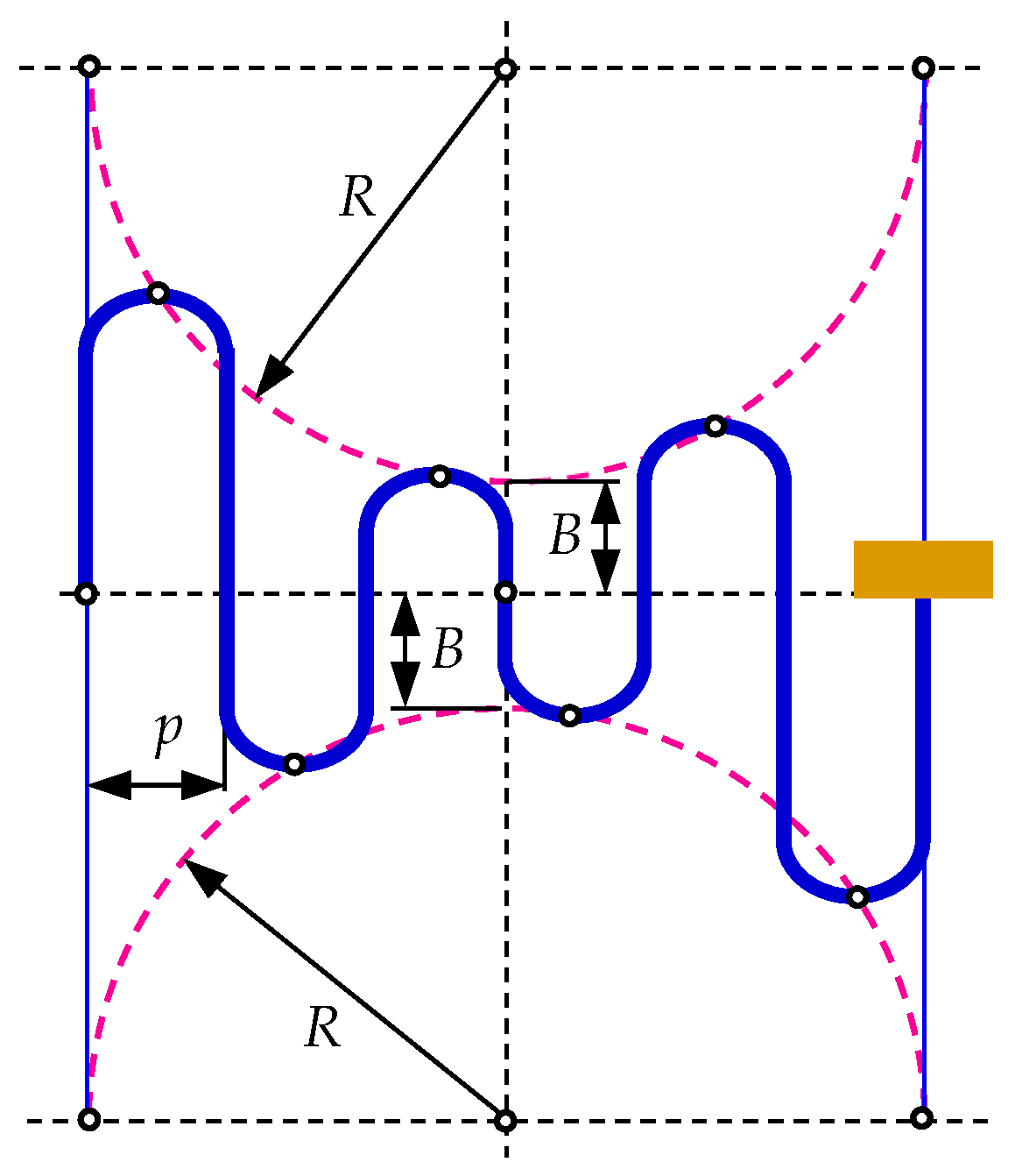
Highly flexible 3D hinges can simply be realized by increasing the hinge length and/or reducing the cross-section dimensions. While both options are limited by evident geometrical constraints, a design solution that is based on the length increase is to pack the component segments of a 3D hinge as densely spatially as possible, like the folded (accordion or serpentine) 2D hinges described in [3,19]—Figure 2 is a schematic representation of a design presented in [3].
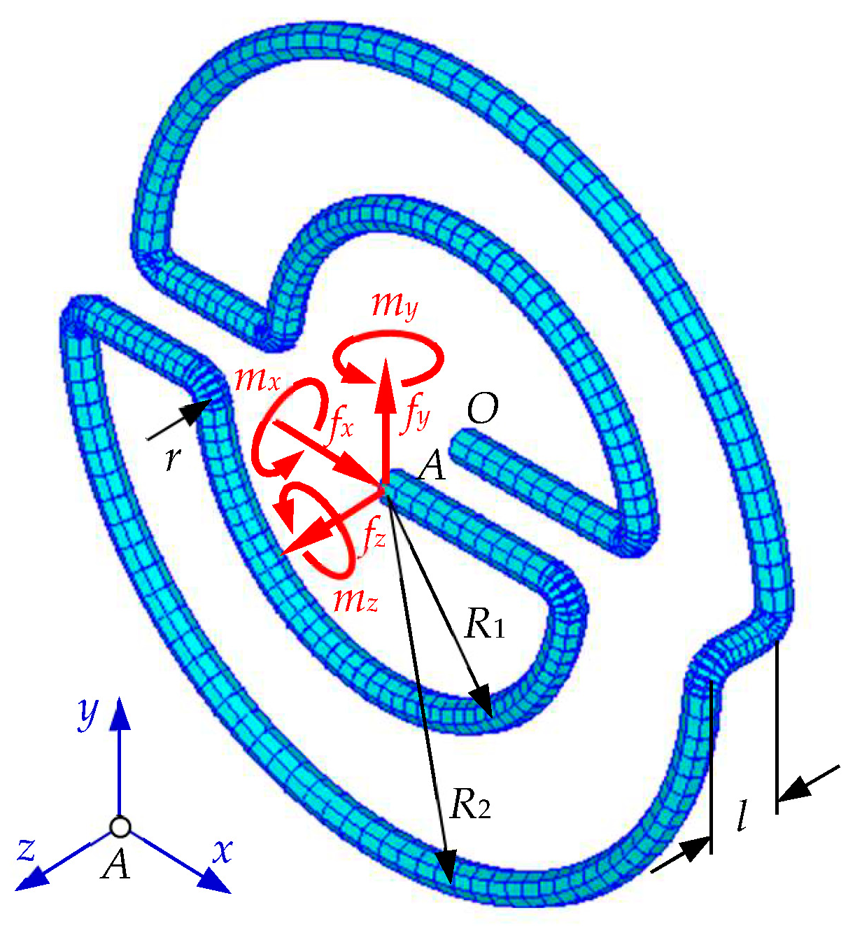
Similar to 2D, highly flexible folded hinges, we propose here a new 3D monolithical hinge, which serially couples several straight- and circular-axis segments in a folded and compact manner to achieve large displacements with relatively small external loads. This design can readily be implemented in flexible manipulators or joy-stick type devices that need to cover an extended 3D workspace. The new hinge can also be implemented in bioinspired soft robotics and actuation applications such as to those described in [26,27,28].
The first half of the paper derives an analytical compliance matrix model of the hinge, which links the six 3D loads to the resulting six displacements at one end of the hinge; the model can be used for either direct or inverse kinematic calculations. The geometric model used to formulate the hinge compliance matrix is simplified as it excludes the corner-filleted portions of an actual hinge. The validity of the analytic model is checked by both finite element simulation and experimental testing of a prototype; both methods’ results are very close to the analytical model predictions. The second half part of the paper utilizes the analytical compliance model in conjunction with stress limitations to assess the maximum loads that can safely be applied and the resulting displacements. Both parts comprise sections that analyze the influence of the geometric parameters on the hinge elastic performance.

2. New 3D Flexible Hinge Design

A rendition of the new 3D flexible hinge is illustrated in Figure 3. The hinge is formed of several straight-axis segments that are serially combined with circular-axis segments in two parallel layers (planes). In each of the two planes, the half circular-axis segments have medium radii R1 and R2. A shorter (but flexible) straight-axis segment of length l connects the two planes’ segments along a direction perpendicular to the planes. In order to eliminate sharp corners and to mitigate large stress concentration effects at the vertices where straight-axis and circular-axis segments intersect, short, circular-axis fillet segments of medium radius r are utilized. The radius r is sufficiently small to avoid altering the hinge elasticity as provided by the half-circle and straight-axis segments. All segments have the same constant circular cross-section of diameter d. Figure 3 also shows the six loads (three forces and three moments) that are applied at the hinge end A in the Cartesian frame Axyz.
The two-plane configuration is primarily necessary to avoid spatial superposition of the four straight-axis segments that are parallel to the x-axis. This layered design (which can be expanded to more than two parallel planes) also enhances the overall hinge flexibility as it allows for additional bending due to the straight-axis segment that is parallel to the z-axis.

3. Analytical Compliance Model

3.1. Model Derivation

The aim here is to relate a three-dimensional load vector [f] = [fx fy mz mx my fz]T that is applied at the end A of the flexible hinge of Figure 3 to the resulting displacement vector [u] = [ux uy θz θx θy uz]T at the same point by means of a compliance matrix [C] in the form: [u] = [C][f]. The symbols f, m, u, and θ stand for force, moment, displacement, and rotation angle, respectively. The first three elements in both [u] and [f] are in-plane elements (due to their effect in the xy plane) while the other three elements in the two vectors are out-of-plane elements.
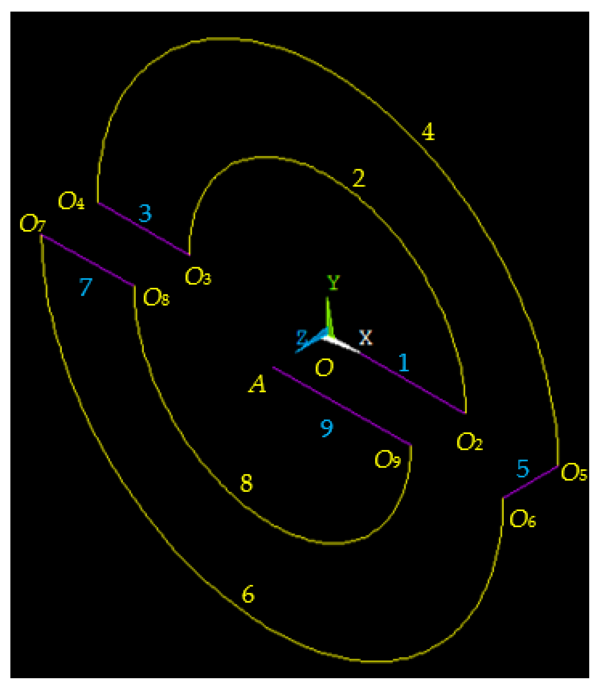
The skeleton-representation flexible hinge of Figure 4 has a simplified geometry that eliminates all filleted (rounded) portions of the actual hinge of Figure 3. The simplified configuration is formed of nine segments, of which five are of straight-axis and four are semicircles. The analytical compliance model is derived based on this simplified geometry. Due to the segment serial connection, the hinge compliance matrix is calculated as:
C = C A = i = 1 9 C A ( i ) = i = 1 9 T A O i ( i ) T R ( i ) T C O i ( i ) R ( i ) T A O i ( i ) .
The global reference frame Axyz is shown in Figure 3 (the frame OXYZ represented in Figure 4 is placed at the fixed hinge end O and is only shown for reference purposes). In Equation (1), the local-frame compliance matrices of the nine segments are expressed as:
C O i ( i ) = C O i , i p ( i ) 3 × 3 0 3 × 3 0 3 × 3 C O i , o p ( i ) 3 × 3 ,
where the subscript “ip” stands for the in-plane components and “op” represents the out-of-plane elements. Consistent with the definition of [u] and [f], the 3 × 3 in-plane compliance matrix of Equation (2) is formulated as:
C O , i p ( i ) = C u x f x ( i ) 0 0 0 C u y f y ( i ) C u y m z ( i ) 0 C u y m z ( i ) C θ z m z ( i ) ;       C O , i p ( i ) = C u x f x ( i ) C u x f y ( i ) C u x m z ( i ) C u x f y ( i ) C u y f y ( i ) C u y m z ( i ) C u x m z ( i ) C u y m z ( i ) C θ z m z ( i ) .
The first matrix in Equation (3) defines a straight-axis segment, whereas the second matrix characterizes a circular-axis segment. Similarly, in the same Equation (2), the out-of-plane compliance matrices of straight-axis and of circular-axis segments are:
C O , o p ( i ) = C θ x m x ( i ) 0 0 0 C θ z m z ( i ) C u y m z ( i ) 0 C u y m z ( i ) C u y f y ( i ) ;       C O , o p ( i ) = C θ x m x ( i ) C θ x m y ( i ) C θ x f z ( i ) C θ x m y ( i ) C θ y m y ( i ) C θ y f z ( i ) C θ x f z ( i ) C θ y f z ( i ) C u z f z ( i ) .
Generic straight-axis and circular-axis segments are depicted in skeleton representation in Figure 5. The local-frame compliances that populate the matrices of Equations (3) and (4) are provided in Appendix A.
Figure 6 describes the axial dimensions of the nine component segments, their connection, together with the local reference frames.
With respect to the circular-axis segments, it should be noted that segments 4 and 6 of Figure 4 and Figure 6a have their axes rotated (mirrored) around the yi axes, and therefore their in-plane axes are xim instead of xi—which is shown in Figure 4. This mirroring effects into minus signs in front of the compliances C u x f y ( i ) , C u y m z ( i ) , C θ x m y ( i ) , C θ y f z ( i ) —see [3], for instance.
The translation matrix of Equation (1) is defined as:
T A O i ( i ) = 1 0 0 0 0 0 0 1 0 0 0 0 Δ y i Δ x i 1 0 0 0 0 Δ z i 0 1 0 Δ y i Δ z i 0 0 0 1 Δ x i 0 0 0 0 0 1 ,
where the offsets Δxi, Δyi, and Δzi represent the Cartesian x, y, z distances measured from the end A to the local origin Oi of any of the nine segments—they are expressed in Table A1 of Appendix B; note that the offset Δyi is zero for all segments. The rotation matrix of Equation (1) is calculated as:
R ( i ) = R ψ ( i ) R θ ( i ) R φ ( i ) ,
where φ, θ, and ψ represent three consecutive coordinate rotations that enable to position the local frame of a segment with respect to the global frame: φ is the rotation around the global z-axis, θ is the rotation around the new (rotated) local x-axis, and ψ is the rotation angle around the local z-axis resulting after the previous (last) rotation—see [3] for more details. All segments, except segment 5, are in planes parallel to the global xy plane, and consequently, their rotation matrix is R ( i ) = R φ ( i ) since the other two rotation matrices are unity matrices. This particular matrix is defined as:
R ( i ) = R ( i * ) 0 3 × 3 0 3 × 3 R ( i * ) ;       R ( i * ) = cos φ i sin φ i 0 sin φ i cos φ i 0 0 0 1 .
The local plane x5y5 of segment 5 is not parallel to the global plane xy, and therefore the rotation matrices R ψ ( i ) , R θ ( i ) are not unity matrices—they are provided in Appendix B, as well.

3.2. Analytical Compliance Model Finite Element Validation

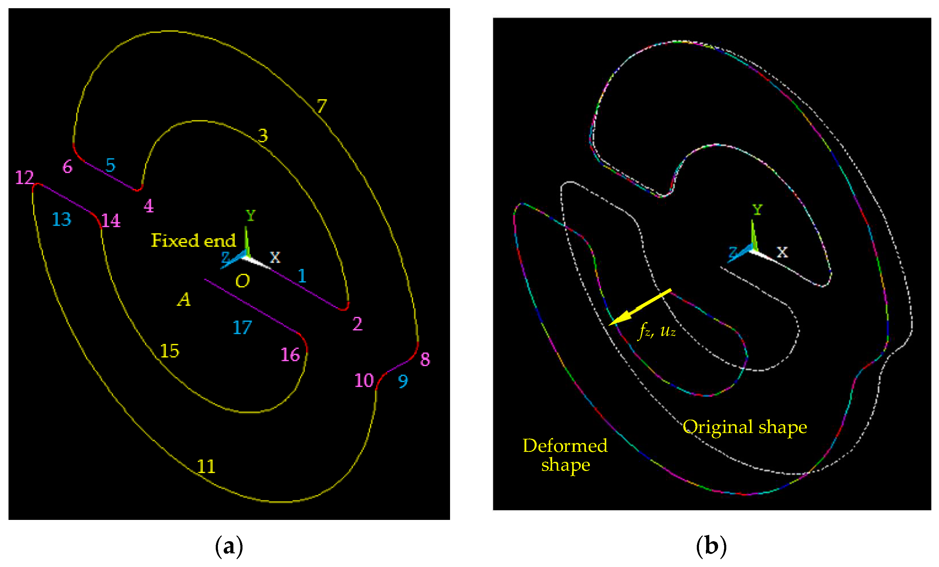
Four different hinge designs were used to compare the compliance values provided by the analytical model (A), which is based on the simplified geometry of Figure 4 and Figure 6 to the finite element (FE) simulation data provided by the ANSYS software 2022 R2 and which utilizes the geometry depicted in Figure 7a where all the corners are filleted by means of circular segments of radius r (shown in Figure 3). The simulation utilized the following material properties: Young’s modulus E = 1.2 × 10¹¹ N/m2 and Poisson’s ratio μ = 0.3. Beam elements with two nodes and six degrees of freedom at each node were used to generate the FE model depicted in Figure 7b, which captures both the original shape and the deformed shape resulting from an axial force fz applied at one end of the device (while the other end is fixed). The individual compliances of the matrix [C] expressed in Equation (1) were obtained with static analysis by sequentially applying unit loads at the free end A of the FE model and by reading the six displacements (three translation displacements and three rotation angles) at the same point. A force fx = 1 N, for instance, generated an x-axis displacement ux = C u x f x , a z-axis rotation angle θz = C θ z f x , and so on. Several meshing densities were utilized before identifying a finite element model that offers sufficient accuracy for a relatively small number of elements. As such, the selected meshing model is formed of 30 elements for the two circular-axis segments of radius R1, 40 elements for the two circular-axis segments of radius R2, 10 elements for the straight-axis segments denoted by 1, 5, 13, and 17 in Figure 7a, 3 elements for segment 5 in the same figure, and 8 elements for all circularly filleted segments.
Table 1 shows the geometric parameters of these designs and Table 2 includes a sample of the 21 individual compliances that form the 6 × 6 compliance matrix of Equation (1). The specific values of Table 1 were in the dimensional range of the experimental prototype that we tested, and which are provided in Section 3.3. The simplified-geometry analytical model results matched the finite element data with a maximum relative error barely in excess of 3%, as shown in Table 2. Similar differences were noted when comparing the analytical and finite element results of a few other designs—those results are not included here. We have also observed that the analytical compliances are slightly larger than the finite element counterparts with consistency, except for a few sets of values of the x-related compliance. This was a strong indication that the simplified-geometry analytical model is sufficiently accurate and can be utilized instead of a more involved model base that would include the fillet regions in the hinge compliance matrix. It should be noted that the differences between the analytical model (based on a fillet-less, simplified geometry) and the finite element model (corresponding to geometry with fillets) results are expected to become larger for larger values of the fillet radius r. However, as mentioned already, the fillets are used at otherwise-sharp corners to reduce stress concentration and not to alter the hinge flexibility, and therefore the errors related to the simplified geometry remain at acceptable levels for small radii r.

3.3. Prototype Experimental Testing

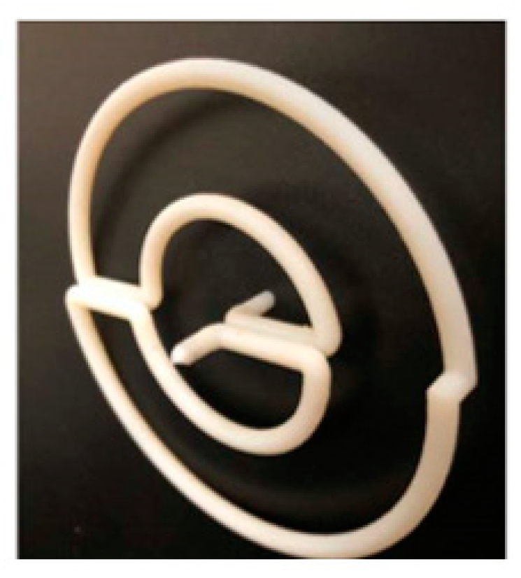
A flexible hinge, whose photograph is shown in Figure 8, was designed and printed in PolyJetTM Material Simulating Engineering Plastics using an Object260 Connex3 three-dimensional printer. This is an additive manufacturing process in the family of fused filament fabrication (or fused deposition modeling—FDM). The basic dimensions of the prototype (see Figure 3) are: R1 = 0.0254 m, R2 = 0.0508 m, l = 0.0063 m, r = 0.0025 m, and the circular cross-section diameter was d = 0.0048 m.
Figure 9 shows two photographs of the experimental test apparatus with a 3D flexible hinge in it. The mechanism was fixed to a small optical board by means of a vertical frame provided with a movable rigid rod, which allowed it to adjust the position of the mechanism at one of its ends along two perpendicular directions. A VC625/M voice-coil actuator was affixed at the other end of the mechanism by means of an aluminum coupler in order to generate motions/deformations along the z-axis. An optoNCDT 1320 laser displacement sensor was fixed to the optical board by means of a fixture that positioned the sensor to a z-axis location within the sensor measuring range. A carbon fiber reflective tab was attached to the top of the actuator to allow for reliable distance measurements with the laser displacement sensor.
Separate experiments were performed to calibrate the actuator. Specifically, relationships between the input current, the displacement, and the pushing or pulling forces developed by the actuator were identified by attaching a force meter to a rigid stage and allowing the actuator to pull on the meter. By finely controlling the current until the weight of the actuator was supported by the magnetic field, the current was then reduced slowly to zero. The polarity of the system was then reversed (to generate a pulling force) and the current was increased slowly to determine the pulling forces developed by the actuator under very fine gradations in current. The experiment was performed ten times and the results were used to obtain a linear relationship between the generated force and the displacement along the z-axis.
To account for the added mass of the aluminum coupler and the carbon fiber tab, the input current to the actuator was adjusted until the test specimen was in the neutral position. The difference between these measured currents and the input current producing the neutral position in the validation of the actuator was used to obtain linear force–displacement relationships. To lessen the error due to static friction between the VCA’s plunger and magnet, the apparatus was vibrated at a small amplitude by holding an electric motor against the frame until the readings reached a steady state after each change in current input. The displacement sensor was also calibrated separately by means of a micrometer translation stage.
Three different experimental test runs were conducted that produced the following values of the z-axis stiffness fz/uz: 42 N/m, 41 N/m, and 43 N/m, which resulted in an average value of 42 N/m. The analytical model utilized the following material properties: Young’s modulus E = 1.92 × 10⁹ N/m2 and Poisson’s ratio 0.35. With these values, the compliance matrix [C] of the entire device was calculated together with its inverse, the stiffness matrix [K] = [C]−1; this generated an analytical value of the stiffness fz/uz of 42.76 N/m, which is very close to the experimental value of 43 N/m. It should be pointed out that compared to the analytical and finite element geometric models, the fabricated prototype has two extra straight-axis segments at its ends, which were needed to affix the specimen in its test apparatus. However, these two segments were very short and, as it is evident from the results, their presence did not alter fundamentally the elastic response of the specimen.

3.4. Geometric Parameters Variation Influence on Compliances

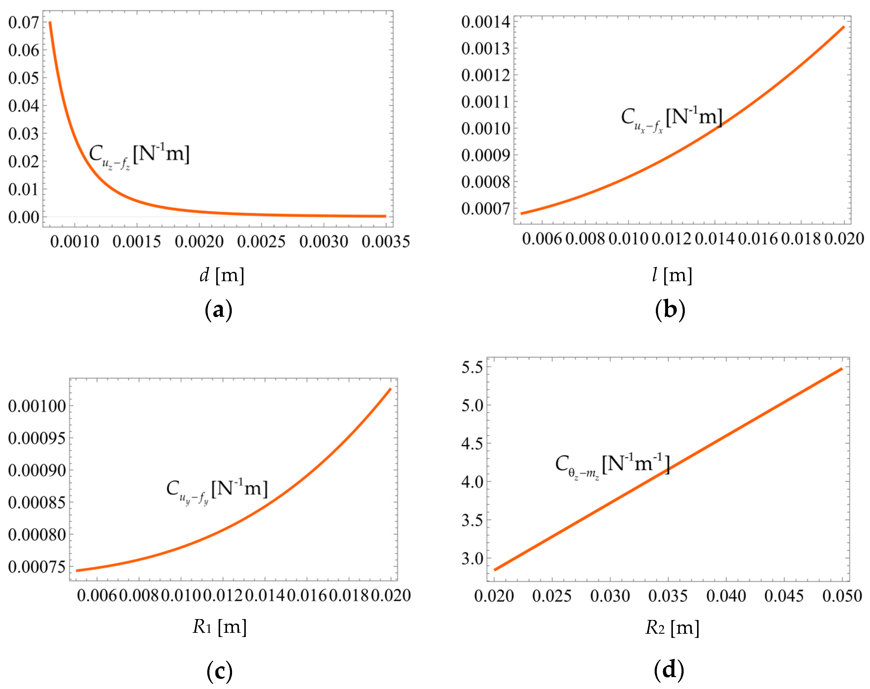
The analytical compliance model is utilized here to study how the flexible hinge geometric parameters d, R1, R2, and l affect the various compliances. It is legitimate to expect that smaller diameters d, as well as larger radii R1, R2, and layer offsets l, result in larger compliances, but it is also important to back these qualitative a priori projections by quantitative assessment. The base (constant) values of the geometric parameters that were used are those of Design 1 in Table 1 together with the material properties of the analytical model, namely: d = 0.002 m, l = 0.006 m, R1 = 0.015 m, R2 = 0.025 m, E = 1.2 × 10¹¹ N/m2, and μ = 0.3. The plots of Figure 10 show the variation of four different compliances in terms of one geometric parameter; the plots confirm the predictions stated above. Similar trends are displayed by all other compliances whose plots are not included here.
While the compliances display nonlinear variations with d, l and R1, as illustrated in Figure 10a–c, they increase quasi-linearly with R2, as shown in Figure 10d.

4. Stress Limitations to Load and Displacement with Analytical Compliance Model

The load [f] that can safely be applied at one end of the hinge is limited and can be assessed in terms of the maximum stress levels. With the safe load, the maximum displacement [u] can be determined by means of the hinge compliance matrix as [u] = [C][f]. Under load, the flexure hinge cross-section is subjected mainly to bending around two axes, axial load, and torsion. As a result, normal stresses σ and tangential stresses τ do occur, which can be combined into an equivalent normal stress σeq by means of available yield criteria, such as the von Mises criterion, according to which:
σ e q = σ 2 + 3 τ 2                   σ a = σ max 2 + 3 τ max 2 .
Equation (8) also includes its limit formulation, which utilizes the allowable stress σa that is generated by maximum stresses/loads. Presumably, the fixed end O of the flexible hinge in Figure 3 is carrying the maximum load, which would generate the maximum stresses. However, as shown in the same Figure 3, utilizing O to express the loads would remove the (bending) effect of the force fz (because fz passes through O), which is nonetheless a relevant component, especially when the flexure hinge is utilized in a piston-type, translation motion along the z-axis. Consequently, one can select another point, relatively close to O, for instance point O2 of Figure 4 and Figure 6a, which is the other end of segment 1. In order to simplify notation point O2 is denoted by D in the following, as also shown in Figure 6a. To evaluate the normal and tangential stresses on the cross section at D, we need to transfer the original load located at A, which is [f]; this is achieved by the following translation:
f D = T D A f       or       f D x f D y m D z m D x m D y f D z T = T D A f x f y m z m x m y f z T .
The translation matrix of Equation (9) is calculated as in Equation (5) with the following offsets (measured from A to D in the global frame at A):
Δ x = R 1 ,     Δ y = 0 ,     Δ z = l     .
The six components of [fD] allow expressing the axial force resultant N, the bending moment resultants My, Mz, as well as the torsion moment resultant Mt applied to the cross section at D:
N = f D x = f x ,     M y = m D y = m y + l f x + R 1 f z ,     M z = m D z = m z R 1 f y ,     M t = m D x = m x l f y     .
Assuming that Mz is positive and given that N and My are positive, as shown in Equation (11), the maximum normal stress is expressed as:
σ max = d M y 2 + M z 2 2 I + N A = d m y + l f x + R 1 f z 2 + m z R 1 f y 2 2 I + f x A , = 32 π d 3 m y + l f x + R 1 f z 2 + m z R 1 f y 2 + 4 π d 2 f x
where A = πd2/4 and I = πd4/64 are the circular cross-section area and axial moment of inertia. The maximum normal stress occurs at a point P on the circumference of the circular cross-section, as illustrated in Figure 11. The neutral axis of the cross-section (a line that is the locus of zero normal stresses) is defined by the equation:
σ = M z I y + M y I z + N A = 0             β = tan 1 M y M y
and passes through points M and N. The neutral axis, together with its inclination angle β, are drawn and identified in Figure 11.
The maximum tangential stress, which is due to the torsion moment Mt occurs on the circumference, as well, and has the following equation at any point, including P:
τ max = M t d 2 I p = 16 π d 3 m x l f y ,
where Ip = πd4/32 is the circular cross-section polar moment of inertia. The maximum normal stress of Equation (12) and the maximum shear stress of Equation (14) are substituted in the limit expression of Equation (8); the resulting expression can be regarded as an equation enabling to determine only one of the six load components of [f].
Of the multitude of possibilities, we are analyzing the case where all load components at A are zero except for fz. Equation (8), together with Equations (12) and (14), as well as [u] = [C][f], yield:
f z = π d 3 σ a 32 R 1 ;     u x = C u x f z f z ,   u y = C u y f z f z ,   θ z = C θ z f x f z ,   θ x = C θ x f x f z ,   θ x = C θ y f x f z ,   u z = C u z f z f z .
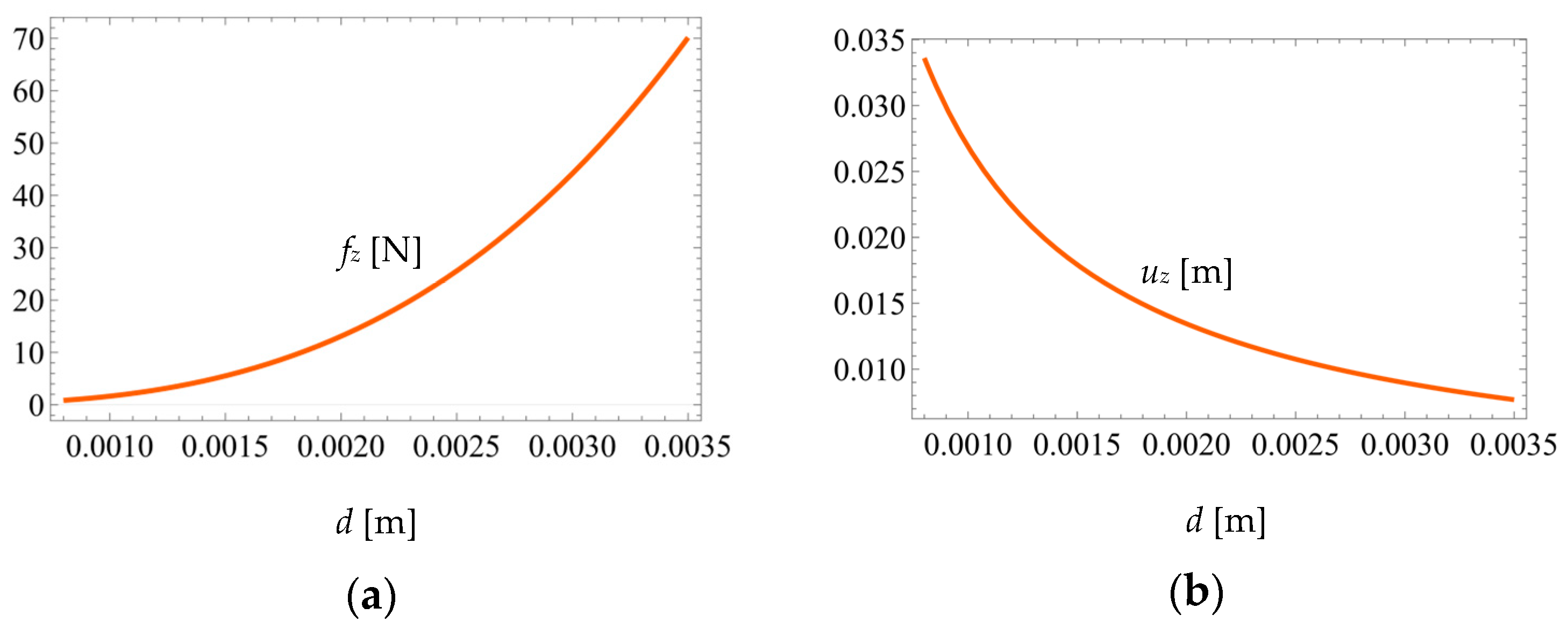
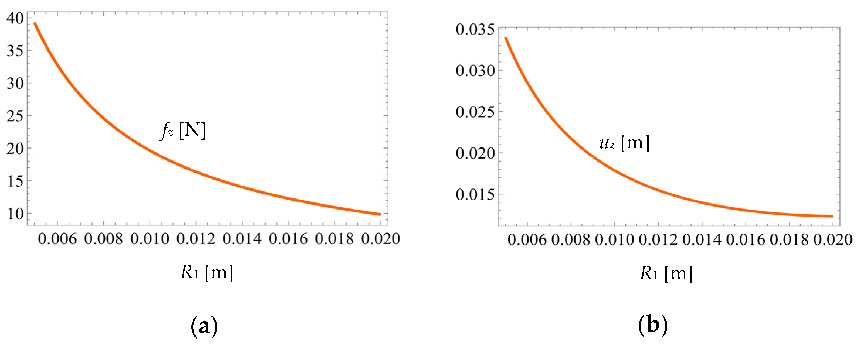
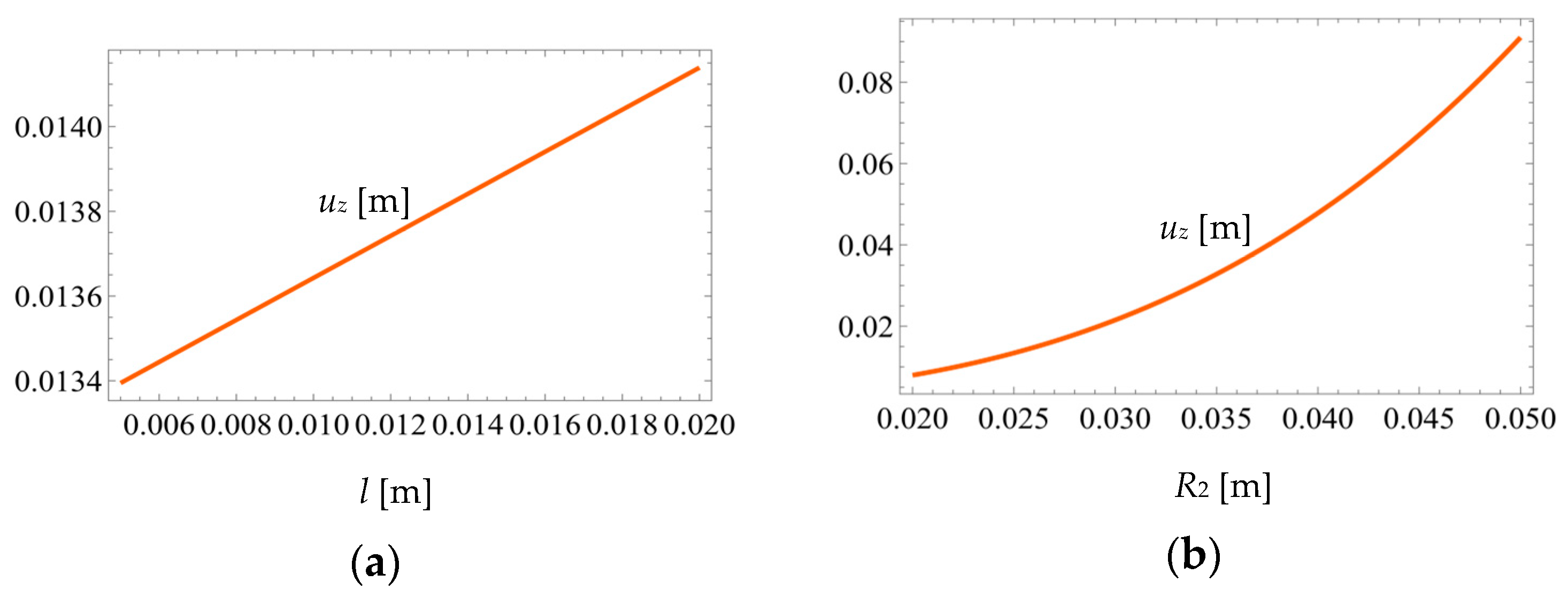
As pointed out in Equation (15), the force fz depends only the hinge diameter d and the inner radius R1. However, any of the six displacements/rotations expressed in the same Equation (15) are functions of all four parameters defining the hinge configuration through their respective compliances. The following Figure 12, Figure 13 and Figure 14 plot the variations of fz and uz when d, l, R1, and R2 range the intervals utilized in the graphics of Figure 10 for the base (constant) values of Design 1 described in Table 1.
As seen in Figure 12, when the diameter values range from 0.001 m to 0.0035 m, the force fz increases nonlinearly up to a value of approximately 70 N. Conversely, the hinge endpoint displacement uz decreases nonlinearly, which indicates that the compliance defining uz in Equation (15) is dominant and its decrease outweighs the force increase.
Increasing the inner radius R1 makes both the force fz and the displacement uz to decrease linearly, as illustrated in Figure 13. For small radii, the displacement uz is approximately 0.035 m, which corresponds to a 40 N value of fz.
The displacement uz increases with both l and R2 increasing, as depicted in the graphs of Figure 14a,b. It can be seen that for large values of R2, the displacement uz exceeds 0.08 m.

5. Conclusions

A new three-dimensional (3D) flexible hinge is proposed here to assist in precision manipulation and positioning applications that require coverage of relatively large workspaces. The hinge compact configuration results from serially connecting multiple straight- and circular-axis deformable segments in two layers and a folded manner. An analytical compliance model, which can be used in direct and inverse kinematics, is derived based on the simplified hinge geometry. The model predictions are confirmed via finite element simulation with maximum relative errors of around 3%. A 3D-printed hinge prototype, which was experimentally tested, resulted in a piston-type stiffness of 42 N/m, very close to the analytical-model stiffness. A separate, compliance-based analytical model is developed to evaluate the hinge maximum load and the related displacements when considering the allowable stress levels. The two models are subsequently utilized to analyze the dependency of the hinge performance on geometric parameters. Maximum displacements of 0.08 m and forces of up to 70 N can be achieved with steel hinges defined by an outer radius of 0.05 m and 0.0035 m wire diameter.

Author Contributions

Conceptualization, N.L.; methodology, N.L., M.M., J.H. and M.G.M.; software, N.L. and M.G.M.; validation, N.L., M.M. and J.H.; formal analysis, N.L.; investigation, N.L., M.M., D.M. and J.H.; resources, N.L.; data curation, N.L.; writing—original draft preparation, N.L.; writing—review and editing, N.L.; visualization, N.L.; supervision, N.L.; project administration, N.L. All authors have read and agreed to the published version of the manuscript.

Funding

This research received no external funding.

Data Availability Statement

Not applicable.

Acknowledgments

The authors are grateful to the time, material and expertise offered by the Manufacturing Laboratory in the College of Engineering at the University of Alaska Anchorage for 3D printing several hinge specimens.

Conflicts of Interest

The authors declare no conflict of interest.

Appendix A

Straight-axis segment compliances
C u x f x ( i ) = l i E A ;     C u y f y ( i ) = l i 3 3 E I ;     C u y m z ( i ) = l i 2 2 E I ;     C θ z f z ( i ) = l i E I ;     C θ x m x ( i ) = l i G I p G = E 2 1 + μ ;     G - shear   modulus ,   μ - Poisson s   ratio .
Circular-axis, half-circle segment compliances
C u x f x ( i ) = 3 π R i 3 2 E I + π R i 2 E A ;     C u x f y ( i ) = 2 R i 3 E I ;     C u x m z ( i ) = π R i 2 E I ;     C u y f y ( i ) = π R i 3 2 E I + π R i 2 E A ;     C u y m z ( i ) = 2 R i 2 E I ;     C θ z m z ( i ) = π R i E I ; C θ x m x ( i ) = C θ y m y ( i ) = π R i 2 E I + π R i 2 G I p ;     C θ x m y ( i ) = 0 ;     C θ x f z ( i ) = π R i 2 2 E I π R i 2 2 G I p ;     C θ y f z ( i ) = 2 R i 2 G I p ;     C u z f z ( i ) = π R i 3 2 E I + 3 π R i 3 2 G I p .

Appendix B

Table A1. Segment offsets, rotation angles and rotation matrices.
SegmentΔxΔzφθψ
10l000
2R1lπ/200
3R1lπ00
4R2l−π/200
5R2lπ/2−π/2−π/2
6R20π/200
7R20000
8R10−π/200
9R10π00
Rotation matrices of out-of-plane hinge segment 5
R ψ ( 5 ) = R ψ ( 5 * ) 0 3 × 3 0 3 × 3 R ψ ( 5 * ) ;       R ψ ( 5 * ) = cos ψ sin ψ 0 sin ψ cos ψ 0 0 0 1 ; R θ ( 5 ) = R θ ( 5 * ) R θ ( 5 * * ) R θ ( 5 * * ) R θ ( 5 * ) ;     R θ ( 5 * ) = 1 0 0 0 cos θ 0 0 0 cos θ ;       R θ ( 5 * * ) = 0 0 0 0 0 sin θ 0 sin θ 0

References

  1. Paros, J.M.; Weisbord, L. How to design flexure hinges. Mach. Des. 1965, 37, 151–156. [Google Scholar]
  2. Smith, S.T. Flexures: Elements of Elastic Mechanisms; Gordon & Breach: Amsterdam, The Netherlands, 2000. [Google Scholar]
  3. Lobontiu, N. Compliant Mechanisms: Design of Flexure Hinges, 2nd ed.; Taylor and Francis (CRC Press): Boca Raton, FL, USA, 2020. [Google Scholar]
  4. Wu, Y.; Zhou, Z. Design calculations for flexure hinges. Rev. Sci. Instrum. 2002, 73, 3101–3106. [Google Scholar] [CrossRef]
  5. Chen, G.; Liu, X.; Gao, H.; Jia, J. A generalized model for conic flexure hinges. Rev. Sci. Instrum. 2009, 80, 055106. [Google Scholar]
  6. Tian, Y.; Shirinzadeh, B.; Zhang, D. Closed-form compliance equations of filleted V-shaped flexure hinges for compliant mechanism design. Precis. Eng. 2010, 34, 408–418. [Google Scholar] [CrossRef]
  7. Linβ, S.; Erbe, T.; Zentner, L. On polynomial flexure hinges for increased deflection and an approach for simplified manufacturing. In Proceedings of the 13th World Congress in Mechanism and Machine Science, Guananjuato, Mexico, 19–25 June 2011. [Google Scholar]
  8. Vallance, R.R.; Haghighian, B.; Marsh, E.R. A unified geometric model for designing elastic pivots. Precis. Eng. 2008, 32, 278–288. [Google Scholar] [CrossRef]
  9. Li, Q.; Pan, C.; Xu, X. Closed-form compliance equations for power-function-shaped flexure hinge based on unit-load method. Precis. Eng. 2013, 37, 135–145. [Google Scholar]
  10. Lin, R.; Zhan, X.; Fatikow, S. Hybrid flexure hinges. Rev. Sci. Instrum. 2013, 84, 085004. [Google Scholar] [CrossRef]
  11. Li, L.; Zhang, D.; Guo, S.; Qu, H. Design, modeling, and analysis of hybrid flexure hinges. Mech. Mach. Theory 2019, 13, 300–316. [Google Scholar] [CrossRef]
  12. Wu, J.; Zhang, Y.; Cai, S.; Cui, J. Modeling and analysis of conical-shaped notch flexure hinges based on NURBS. Mech. Mach. Theory 2018, 128, 560–568. [Google Scholar] [CrossRef]
  13. Hsiao, F.Z.; Lin, T.W. Analysis of a novel flexure hinge with three degrees of freedom. Rev. Sci. Instrum. 2001, 72, 1565–1573. [Google Scholar] [CrossRef] [Green Version]
  14. Lee, V.; Ziegert, J. Hybrid bi-directional flexure joints. In Proceedings of the Proceedings of ASPE 2007 Annual Meeting, Dallas, TX, USA, 14–19 October 2007. [Google Scholar]
  15. Bi, S.; Zhao, S.; Zhu, X. Dimensionless design graphs for three types of annulus-shaped flexure hinges. Precis. Eng. 2010, 34, 659–666. [Google Scholar]
  16. Rad, F.P.; Vertechy, R.; Berselli, G.; Parenti-Castelli, V. Analytical compliance analysis and finite element verification of spherical flexure hinges for spatial compliant mechanisms. Mech. Mach. Theory 2016, 101, 168–180. [Google Scholar]
  17. Bilancia, P.; Berselli, G. An overview of procedures and tools for designing nonstandard beam-based compliant mechanisms. Comput. Aided Des. 2021, 134, 103001. [Google Scholar] [CrossRef]
  18. Li, J.; Liu, H.; Zhao, H. A compact 2-DOF piezoelectric-driven platform based on “Z-shaped” flexure hinges. Micromachines 2017, 8, 245. [Google Scholar] [CrossRef] [Green Version]
  19. Qiu, L.; Liu, Y.; Yu, Y.; Bai, Y.B. Design and stiffness analysis of a pitch-varying folded flexure hinge (PFFH). Mech. Mach. Theory 2021, 157, 104187. [Google Scholar]
  20. Qiu, L.; Li, C.; Dai, S.; Yu, Y. Research on the line-arc-line constant-torque flexure hinge (LAL-CTFH) based on improved pseudo-rigid-body model (PRBM). Mech. Mach. Theory 2002, 174, 104878. [Google Scholar] [CrossRef]
  21. Abedi, K.; Shakhesi, E.; Seraj, H.; Mahnama, M.; Shirazi, F.A. Design and analysis of a 2-DOF compliant serial micropositioner based on “S-shaped” flexure hinge. Precis. Eng. 2023, 83, 228–236. [Google Scholar] [CrossRef]
  22. Iandiorio, C.; Salvini, P. Elasto-kinematics and instantaneous invariants of compliant mechanisms based on flexure hinges. Micromachines 2023, 14, 783. [Google Scholar] [CrossRef]
  23. Cao, L.; Dolovich, A.T.; Chen, A.; Zhang, W. Topology optimization of efficient and strong hybrid compliant mechanisms using a mixed mesh of beams and flexure hinges with strength control. Mech. Mach. Theory 2018, 121, 213–227. [Google Scholar] [CrossRef]
  24. Lobontiu, N.; Hunter, J.; Keefe, J.; Westenskow, J. Tripod mechanisms with novel spatial Cartesian flexible hinges. Mech. Mach. Theory 2022, 167, 104521–104537. [Google Scholar] [CrossRef]
  25. Lobontiu, N.; Hunter, J.; Robles, B. New 3D Cartesian flexible hinge and tripod mechanisms: Stress-based maximum load and displacement with compliance model. Rom. J. Tech. Sci. Appl. Mech. 2022, 67, 43–59. [Google Scholar]
  26. Zolfagharian, A.; Lakhi, M.; Ranjbar, S.; Tadesse, Y.; Bodaghi, M. 3D printing non-assembling compliant joints for soft robotics. Results Eng. 2022, 15, 100558. [Google Scholar] [CrossRef]
  27. Alshebly, Y.S.; Mustapha, K.B.; Zolfagharian, A.; Bodaghi, M.; Mohamed Ali, M.S.; Almurib, H.A.; Nafea, M. Bioinspired pattern-driven single-material 4D printing for self-morphing actuators. Sustainability 2022, 14, 10141. [Google Scholar] [CrossRef]
  28. Zolfagharian, A.; Gharaie, S.; Gregory, J.; Bodaghi, M.; Kaynak, A.; Nahavandi, S. A bioinspired compliant 3D-printed soft gripper. Soft Robot. 2022, 9, 680–689. [Google Scholar] [CrossRef] [PubMed]
Figure 1. Flexible hinges: (a) Straight-axis, 1D with one segment; (b) 2D with several serial segments; (c) 3D with several serial segments.
Machines 11 00825 g001
Figure 2. Skeleton representation of a 2D folded flexible hinge.
Machines 11 00825 g002
Figure 3. Configuration of new 3D two-layer flexible hinge with end loads.
Machines 11 00825 g003
Figure 4. Skeleton hinge representation with simplified geometry and sharp vertices.
Machines 11 00825 g004
Figure 5. Basic skeleton segments in local frames: (a) Straight-axis member; (b) Circular-axis member.
Machines 11 00825 g005
Figure 6. Component segments with defining geometry and local reference frames: (a) Back layer; (b) Connecting segment; (c) Front layer.
Machines 11 00825 g006
Figure 7. (a) Skeleton hinge representation with actual, filleted vertices; (b) Finite element model with original and deformed shapes under a force fz.
Machines 11 00825 g007
Figure 8. Photograph of fabricated prototype for experimental testing.
Machines 11 00825 g008
Figure 9. Photographs of experimental setup with flexible hinge: (a) 3D view; (b) Front view.
Machines 11 00825 g009
Figure 10. Compliance plots showing variation with the: (a) Diameter d; (b) Layer offset l; (c) Inner radius R1; (d) Outer radius R2.
Machines 11 00825 g010
Figure 11. Hinge cross section with bending moments, neutral axis, and resulting normal stress.
Machines 11 00825 g011
Figure 12. Plots showing variations with the diameter d of the: (a) Force fz; (b) Displacement uz.
Machines 11 00825 g012
Figure 13. Plots showing variations with the inner radius R1 of the: (a) Force fz; (b) Displacement uz.
Machines 11 00825 g013
Figure 14. Plots showing variations of the displacement uz with the (a) Layer offset l; (b) Outer radius R2.
Machines 11 00825 g014
Table 1. 3D hinge designs with geometric parameters.
Designd [m]R1 [m]R2 [m]r [m]l [m]
10.0020.0150.0250.00150.006
20.0030.0150.0250.00150.006
30.0030.020.0350.0020.008
40.0030.020.040.00250.008
Table 2. Compliances by analytical model (A) and finite element model (FEA); relative percentage differences (e) between A and FEA results.
DesignResults C u x f x
[N−1m]
C u x m y
[N−1]
C u z f z
[N−1m]
C θ z m z
[N−1m−1]
C u y f y
[N−1m]
1A6.99 × 10−41.098 × 10−21.797 × 10−33.288.647 × 10−3
FEA6.998 × 10−41.081 × 10−21.773 × 10−33.2278.4 × 10−3
e [%]0.1141.5481.3361.6162.856
2A1.383 × 10−42.169 × 10−33.551 × 10−40.6481.71 × 10−4
FEA1.386 × 10−42.135 × 10−33.51 × 10−40.6371.663 × 10−4
e [%]0.2161.5671.1551.6982.749
3A3.67 × 10−43.986 × 10−39.516 × 10−40.8934.552 × 10−4
FEA3.67 × 10−43.92 × 10−39.397 × 10−40.8794.428 × 10−4
e [%]01.6561.2511.5682.724
4A5.092 × 10−44.372 × 10−31.349 × 10−30.986.359 × 10−4
FEA5.094 × 10−44.29 × 10−31.329 × 10−30.9626.16 × 10−4
e [%]0.0391.8761.4831.8373.129
Disclaimer/Publisher’s Note: The statements, opinions and data contained in all publications are solely those of the individual author(s) and contributor(s) and not of MDPI and/or the editor(s). MDPI and/or the editor(s) disclaim responsibility for any injury to people or property resulting from any ideas, methods, instructions or products referred to in the content.