Abstract
Hybrid Manufacturing technologies enable the manufacturability and high manufacturing efficiency of innovative part designs comprising high complexity features which could not otherwise be manufactured in a single or a small number of steps. This study proposes the design of an industrial-grade low-cost fully automated multi-axis hybrid Additive and Subtractive CNC machine for non-metallic parts. It combines operations of a six-axis CNC machining center with a six-axis extrusion 3D printer with automated tool head change for processing parts made of polymer and special 3D printing materials (e.g., carbon fiber reinforced filaments). The design process includes static, dynamic and harmonic response Finite Element Analysis to optimize its structural strength and at the same time to reduce machine component costs down to a few thousand euros for all included components and subsystems, thus making it viable for industrial purposes. In investigated loading scenarios, analysis results show that at the brim of a 200 mm diameter round machine table, even at its most unfavorable angular positions, maximum deformation was no more than 0.24 mm, with a factor of safety in the magnitude of 10 to 20 while applying cutting force profiles with amplitudes up to 100 N, which exceedingly satisfies structural specifications for the proposed machine design operation.
1. Introduction
High-tech applications, such as embedded electronic systems and biomedical diagnostic devices, have led to a need for high complexity multi-functional components comprising multiple materials. Traditionally, this type of component is manufactured by a few consecutive processes carried out in different machines within controlled environment rooms, thus introducing error, increased set-up and dead-times and elevated costs. To that end, it is preferable to perform all processes in a single environment to maximize productivity, repeatability and process efficiency. The term Hybrid Manufacturing (HM), and, respectively, Hybrid Machine Tools (HMTs), refers to the combination of different manufacturing processes in a single work environment, preferably enclosed or otherwise restricted [1,2,3]. For the purposes of the present study, HMTs are called the Computerized Numerical Control (CNC) machine tools; their functions are controlled by a control unit or a computer, and they combine material removal stages, known as Subtractive Manufacturing (SM), and material addition stages, commonly addressed as 3D printing or, more formally, Additive Manufacturing (AM), for the manufacture of components in a sequential or a parallel manner [4,5].
While most components can be made by either one of these two methods (SM or AM), modern manufacturing needs have driven machine tool manufacturers to upgrade the existing machine tools, combining these machining methods in order to reduce production time, energy consumption, as well as material waste, with the ultimate goal of reducing total production cost per unit without sacrificing part quality. This is achieved by replacing the rough machining stage with material deposition, thus minimizing material usage and cutting tool wear, therefore cutting energy usage and cost. Moreover, with the extended introduction of Topology Optimization and Generic Design techniques for component weight minimization, as in the ones for the aircraft, aerospace and transportation applications, the use of HM methods is inevitably irreplaceable [4,6,7].
As with any mechanism with moving or rotating parts, vibrations can appear during hybrid machine tool operations. These vibrations must be calculated and addressed properly ideally from the machine design stage, as they can cause deformations of the machine structure, leading to part failure or even, in extreme cases, to machine tool failure. Vibrations can be described as a set of mode parameters, including natural frequency, operation pattern and damping. Natural frequency is an important component of the resonance effect. If the external excitation frequency is the same as that of the structure, it can cause permanent deformations [8,9]. In the literature, three types of dynamic structural analysis techniques are known: (a) the distributed mass beam method, (b) the irradiated fixed beam method, and (c) the Finite Element Method/Analysis (FEM/FEA). FEA is one of the most useful tools for simulating physical models, from very simple to very complex ones, and in most cases, such as the one analyzed in this study, it is considered appropriate and efficient enough. Analyses’ accuracy performed on CAE software depends mainly on the structure and the quality of the mesh. In this work, the dynamic characteristics of machine tools were studied using FEA, as it incorporates material properties, geometric properties and boundary conditions.
The aim of this study is to design a novel hybrid numerically controlled machine tool, which combines a six-axis CNC machine center with a six-axis 3D printer, to produce industrial grade high complexity parts made of polymers, elastomers and special type composites (e.g., carbon fiber reinforced filament) that require minimal finishing by hand to obtain the final product in the shortest possible time. Static and dynamic analysis were iteratively used in the design process, thus providing knowledge in improving design features and predicting machine tool behavior under specific loads.
The rest of the paper is structured as follows. Section 2 presents the state-of-the-art for HMT and relevant research on existing HM technologies. In Section 3, an overall assessment of HM technologies was carried out to stress the importance of this new manufacturing sector and its capabilities to push the boundaries of Manufacturing Technologies. Section 4 analyzes subsystems that can be used in HMT and presents the design choices the authors have made along with the respective machine modeling. In Section 5, loading scenarios, boundary conditions and meshing that were implemented during the FEA are described. Section 6 presents FEA results for the chosen scenarios and provides a critical analysis, while Section 7 discusses these results and gives sequencing examples for HMT operation. Finally, Section 8 presents the conclusions of the study and provides recommendations for further work.
2. State of the Art
Hybrid Manufacturing (HM) is a recognized term for automatically combining at least two processing classes or at least two subcategories of the same processing class without human intervention between processing phases, as explained by Rajurkar et al. [10]. This definition is somewhat vague since the combination of two or more material removal processes is necessary in most machined parts. Kozak and Rajurkar [11] adjusted the definition in the sense that the performance characteristics of hybrid processing need to be significantly different than those of individual procedures when performed separately. In 2001, Aspinwall et al. [12] introduced the term “assisted machining”, which refers to HMTs that combine two or more material removal processes which are applied independently in the same machine, further reinforcing the HM definition. In the early 2010s [13], the realization that the term HM should be used in a broader sense to include processes other than machining led some authors to relate HM to any combination of processes which involves various forms of deformation energy that are used simultaneously in the same processing zone.
Fessler et al. [14] and Klocke and Wirtz [15] combined an older type of Laser Directed Energy Deposition (L-DED or, simpler, DED) system consisting of a laser with a coupled powder feed system (a device widely used for laser coating at the time) with a high-speed milling machine for performing material removal operations after intermediate metal deposition stages. Nevertheless, research about HM in the sense of alternating additive and material removal stages began to expand and consolidate only in the mid-2000s through the adaptation of either Metal Additive Manufacturing (MAM) or material removal operations. Kerschbaumer and Ernst [16], for example, reviewed previous concepts and provided further insights into tool path generation, laser power source performance and powder feed adaptation strategies. Sreenathbabu et al. [17] incorporated Gas Metal Arc Directed Energy Deposition (GMA-DED) into a CNC milling system for machining irregular layers in a more precise planar shape. Song et al. [18] assembled two Gas Metal Arc (GMA) lenses and a laser on a milling machine to obtain a hybrid multitasking system capable of providing a more accurate and selective metal deposition through an automated tool switching mechanism.
In the same direction, Kovacevic and Valant [19] patented a six-axis robotic system for the manufacture of metal components with plasma and laser-based deposition capabilities. Xinhong et al. [20] developed a system that combines the AM by Plasma Arc Direct Energy Deposition (PA-DED) and SM by milling to fabricate a built-in double air propeller made of a super nickel alloy. Such test cases prompted the machine tool industry to develop and commercialize the first hybrid AM/SM systems in the early 2010s. Thus, some of the traditional CNC manufacturers have introduced HMT models based on the DED technology for the AM operations. For example, DMG Mori introduced the LASERTEC 65 3D Hybrid model [21], Mazak the INTEGREX i-400AM, Okuma the MULTUS U laser EX model, Hermle the C-400 model and Optomec the CS series models, among others. All these models offer multiple nozzle DED heads and multi-axis CNC machining, suitable for making from scratch or repairing (cladding) medium to large metallic parts made of Ti alloys and high-performance steels with intricate geometries, such as impellers, gas and water turbine/compressor blades, jet engine nozzles, etc. These systems are based on DED technology due to its greater flexibility to combine AM and SM in a single machine [22].
However, other CNC machine tool manufacturers focused on Powder Bed Fusion (PBF) technology for AM operations in their HMTs, such as Matsuura with its Lumex Avance 25 and Sodick with its OPM250L and 350L models. These systems combine Laser Powder Bed Fusion (LPBF) deposition with high-speed milling and are gaining attention for their ability to perfect external contours, surface roughness and corrosion characteristics in dies and molds [23].
In order to create interchangeable AM heads that can fit in a typical CNC machine tool without serious intervention in its operations, a couple of companies developed stand-alone tool heads that can be fitted in the spindle with a simple tool change. Thus, 3D Hybrid offers GMA-DED, L-DED and cold spray heads (commonly used in coating applications) and Hybrid Manufacturing Technologies offers its AMBIT series for integration into CNC machining centers.
Material extrusion AΜ processes are among the most extensively implemented ones and are capable of producing parts with relatively high accuracy at a low cost. However, use of this technology involves some limitations, such as low mechanical strength in regard to the size of a component and high processing time when high part accuracy is needed. Due to the low cost of thermoplastic materials with fair theoretical properties such as nylon and ABS, their use has overtaken efforts to cost-effectively manufacture non-functional prototype parts. Fused Deposition Modeling (FDM) or, equivalently, Fused Filament Fabrication (FFF) is one of the most common methods for additively making and prototyping thermoplastics. In FDM, material is mechanically pushed towards a hot end to melt and subsequently through a nozzle for deposition. The material is deposited in a layer-by-layer manner to make components, even highly complex ones. The cartesian or gantry-type mechanism usually implemented in these material extrusion AM machines is the same as the one used in CNC machines or routers. So, several commercially available systems have been introduced to help both amateur makers and professionals take advantage of the use of both AM and SM processes in a single machine. Table 1 presents the existing material extrusion AM/SM hybrid systems that use thermoplastics.

Table 1.
Hybrid systems for manufacturing thermoplastic parts. Specifications taken from respective manufacturers.
5axismaker [24] is a desktop machine tool that offers five-axis milling and three-axis printing, finding uses in dental applications, among others. It creates components from wood, plastic, foam and other materials. It uses software to carve intricate products but only in three dimensions (X, Y and Z). Users must accurately rotate the object by hand or lose the entire toolpath. Creality CP-01 [25] is a modular three-axis machine with exchangeable head attachments for 3D printing, laser engraving and CNC engraving. For the processing heads, CP-01 has several options for different applications. Each head has a universal connector to make any manual change easy, so reconfiguring the machine tool to switch between different functions takes only a few minutes. Materials that this machine is compatible with are PLA, ABS and TRU. As a CNC machine, the CP-01 can process plastic, wood, paper and PCBs. Da Vinci 1.0 pro [26] shares similar characteristics with CP-01, but has extrusion, laser engraving and 3D scanning heads. The Snapmaker 2.0 is built for the lab and provides users with all the manufacturing capabilities that could potentially satisfy amateur applications. Users can swap the 3D printing head for a CNC tool or laser diode. Since the Snapmaker has been referred to as a three-in-one build system, it includes a housing and a rotary unit. The maximum temperature of the nozzle is 275 °C. Equipped with a direct drive extruder, this configuration will have no problems printing with materials such as PLA, ABS, PETG and TPU [27,28]. The ZMorph VX is a machine aimed at professionals and individuals looking for an affordable hybrid machine tool that combines 3D printing and CNC/laser machining for a variety of projects [29,30]. The H-series by Diabase Engineering [31] is a professional tool for the hybrid manufacturing of a vast variety of materials and multi-axis automated CNC machining in a number of industrial sectors, including sportswear, electronics and dental and biomedical applications. A small number of five-axis hybrid machine tools have appeared in the literature that are mainly developed for research purposes, such as in [32], but are far from being industrial grade professional machine tools.
Although extensive research has been carried out on multi-axis machinery [33], methodologies and sequencing [34,35], part quality and error avoidance [36] during HM of metallic parts and multi-axis AM of various materials [37,38], very limited references can be found related to the HM of non-metallic parts. Li, Haghidhi and Yang [39] have developed and tested a multi-axis robot methodology for the HM of polymer parts, showing that it reduces production time, that parts demonstrate better surface quality after removing the staircase error, that it manufactures high quality freeform surfaces through dynamic adjustment of the tool axis direction and that it eliminates the need for support structures because of multi-axis flexibility. Lee et al. [40] integrate FDM and multi-axis CNC machining to overcome disadvantages associated with either processes or developing new applications. Their design allows switching between five-axis machining to FDM, reducing costs for extra actuators without sacrificing workspace, thus building objects without support materials and even enabling metal embedding to increase stiffness. Their system machines complete FDM parts or trim FDM-fabricated freeform surfaces to achieve accurate dimensions and better surface finish. Keating and Oxman [41] proposed an approach for a six-axis robotic fabrication that supports multi-functional and multi-material processes by combining additive, formative and subtractive fabrication, as well as their parallel integration. The robotic arm integrates 3D printing, milling and sculpting by shifting between fabrication modes using different end effectors, and operations were demonstrated on composite material applications. The following combined processes were developed and evaluated: multi-axis plastic 3D printing, direct recycling 3D printing and embedded printing. Duarte et al. [42] proposed a five-axis hybrid manufacturing technique for producing shell-type objects, based on curved layer paths, and applied it to aircraft part test cases. In [43], a hybrid technology that integrates the advantages of 3D printing and five-axis CNC machining was proposed: 3D printing was used to rapidly manufacture the part body, and five-axis machining was used to accurately finish the joining and driving sections. The reliability of the proposed technology was verified through a comparison with conventional technology in the aspects of processing time, surface roughness and dimensional accuracy.
From the above, it can be seen that the development of hybrid systems technology for both metallic and polymer material has a huge growth rate in terms of the production of complex components with greater flexibility and in terms of maintaining high precision in a relatively short production time. Thus, with hybrid processes new research avenues are opened to enhance the capabilities of the processes, minimizing the weaknesses that may arise by extending the scope of application.
The aim of this work is the development of a fully automated six-axis (X-Y-Z-A-B-C) hybrid manufacturing numerically controlled system for non-metallic material that combines conventional multi-axis CNC machining with extrusion based multi-axis AM. Compared to the most common five-axis HMTs, the introduction of the sixth axis offers the flexibility of six DoF robots in multi-material production with multiple manufacturing heads, but at improved machine stiffness and rigidity. This is because the motion mechanisms are divided in different rests instead of working in a dependent sequential way, which induces a higher possibility of vibrations during manufacturing. More specifically, the proposed machine design helps minimize set-up and dead-times through its overall automation, offers high accuracy AM/SM processes based on high-quality parts, improves tool head-type and tool carrying capacity and increases part production flexibility, all within a limited space, thus creating a new category of industrial-grade benchtop hybrid manufacturing systems with an automated tool changer for high-end non-metallic products that need no or minimal post-processing. However, as the main intention of the article is to provide the specifications and the design analysis of the proposed HMT, it does not extend to presenting its full operation, as this is the subject of a subsequent article.
3. Hybrid Manufacturing Assessment
According to international standards (ASME AM223, DIN 8580), manufacturing processes can be divided into three categories: subtractive, additive and formative (Figure 1) [3,5,44,45]. More specifically, SM processes, such as turning, drilling and milling, start with a stock part or bulk material, removing material until the desired geometry is created. In AM processes, material is selectively deposited in successive layers until the final geometry is reached. Finally, in formative processes such as casting and forging, the bulk material is shaped into the desired geometry through molds and tools. Table 2 presents a generic comparison of manufacturing process categories.
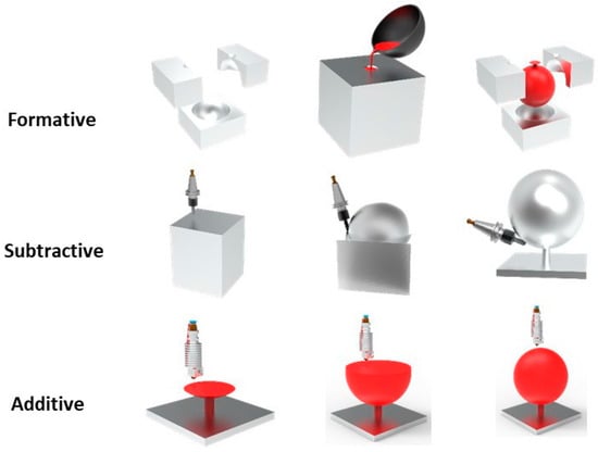
Figure 1.
Formative, subtractive and additive manufacturing processes respectively.
Table 2.
Comparison of manufacturing process categories [44,45].
Manufacturing processes can be combined, thus creating hybrid fabrication processes. The most common hybrid production method is the serial combination of additive with subtractive processes. The component is built entirely through AM, almost to a roughly shaped geometry of the object, then subjected to a finishing SM process to perfect the object’s surfaces and geometric tolerances. The second hybrid manufacturing method alternates iteratively between AM and SM during the construction process on an existing or a new object. AM and SM alternate either at every material layer or at every couple of layers to achieve accuracy in any external and internal geometrical features of an object, e.g., engine cooling pipes or mold cooling/heating channels.
Furthermore, a hybrid system can combine materials, such as polymers, metals, composites, etc., during the additive stages and apply different ones for the creation of a single part, thus creating what is called “multi-material parts” [3,46,47,48]. However, this can be a serious challenge when the melting temperature is significantly different between two materials, which requires special actions to be taken for successful performance [49]. A great deal of materials that can be used in additive processes, either as filament (usually polymers, such as ABS, nylon, PLA, PETG, etc.) or as powder, metals (such as aluminum, copper, stainless steel and titanium) and polymers. As a result, by using different metals in a single multi-stage process, the workpiece acquires better characteristics without compromising its integrity. There are currently two types of HMTs. The first is an off-the-shelf HMT offering both AM and SM, while the second aims to add AM capabilities to an SM machine tool. Adding one or more AM heads to an existing CNC machine allows them to work in parallel with the standard set of subtractive tools. Although the total number of HMTs available is still relatively small, as presented in the previous section, it is a technology that will only be expanded and developed due to its inherent flexibility of combining both processes into one working space, which leads to increased productivity and the ability to create parts that otherwise would be either impossible or very difficult to produce [7,50,51].
Hybrid technology offers several advantages over the material removal or additive process alone. Due to the ability to add material to existing parts, it allows the repair of damaged parts, since the selective addition of material to the parts is performed. At the same time, AM allows the combination of different materials, changing its mechanical properties layer by layer, which can improve its durability, e.g., in car engine connecting rods. Furthermore, it reduces the need for extensive post-processing machining processes, as material is added only where required, for part finishing (Figure 2). Finally, the ability to switch between AM and SM without having to move the piece to another machine tool saves significant time and cost (set-up and down phases) and minimizes all related errors.
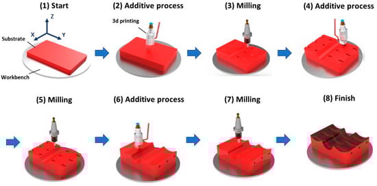
Figure 2.
Generalized process plan for hybrid AM and SM processes.
As with any new technology, HM technology faces a set of pre-challenges, learning curves and questions. The first challenge is the investment and implementation cost associated with the equipment, and whether these costs can be kept low, so that any business can invest in an HMT. Additionally, another question that arises is whether HM technology is able to meet production requirements in a timely manner. HM has been proven in the production of models and unique parts in small batches, as well as in repairs of high quality and complexity parts. Custom on-demand production performed with HM eliminates the need for inventory and minimizes production time, thus resulting in overall cost reduction of the total production. Moreover, HM can effectively produce complex parts or perform complex repairs, e.g., in molds by adding material to enhance it for added durability. Over time, more and more industrial and other sectors are becoming aware of the benefits of using HM systems. HM technology is at the beginning of a new technological leap which fits smoothly with the Industry 4.0 and Industry 5.0 transition that will dominate the manufacturing world in the following years. The combination of both AM and SM in one machine enables innovative ideas and leads to production disruption. Instrumental in HM success is process optimization, which can be applied seamlessly so as to provide design and manufacturing flexibility while maintaining strict specifications for the produced parts.
4. Multi-Axis Hybrid Machine Design
Design is a crucial stage in manufacturing parts for an assembly, as it determines manufacturing processes, cost, functionality and aesthetics of the overall product. At the same time, design must see to machine component simplification, thus maintaining production and assembly at low-cost levels. As mentioned in the previous sections, the aim of this study is to design a machine that combines the operations of a six-axis CNC machining center and a six-axis extrusion 3D printer, which will be used for making polymer, elastomer and special type composite parts. Additionally, this machine should be able to build intricate part geometries that are difficult or impossible to produce with conventional means in a reasonable amount of time [34,52,53,54].
4.1. Structural Material for the Frame
An HMT is a complex structure consisting of a number of functional mechanisms and sub-assemblies [53]. Various materials can be used for the machine components, including ferrous and non-ferrous alloys and engineering plastics. Frame material must be strong and rigid enough to support the weight of the frame, the motors, the drive mechanisms and the spindle, as well as to withstand cutting forces and loads. Furthermore, in order to avoid deformations owing to static and dynamic loads, as well as thermal loads during operation, high rigidity of the machine frame is required, as it affects machining accuracy. In addition, moving parts and total weight is important because mass contributes to both static and acceleration forces. Thus, a combination of proper cross section and material of the structural parts should supply the required mechanical properties at a reasonably low cost. Various materials were examined, including metals, mainly steel and aluminum alloys, and a number of plastics, including high-density polyethylene and ultra-high molecular weight polyethylene. Their properties were collected, compared and evaluated as a possible selection for the proposed HMT frame. Compared properties include coefficient of elasticity, density and yield strength. The ratio of elasticity to density was calculated to offer rigidity and the ratio of strength to density was introduced so as to evaluate strength relative to weight. At the same time, costs for given part dimensions for different materials were retrieved from suppliers and are shown in Table 3 [33].
Comparing metals and plastics is not easy, as metals have significantly higher strength and modulus of elasticity, but they also weigh more and are harder to process. It is important to note that both the studied steel and aluminum alloys, which are appropriate for the specific application, have similar strength to weight properties, as indicated by the specific modulus E/ρ ratio, while high quality aluminum has a significant strength advantage over weight. Following a material section process for the machine components, as proposed by Ashby [55], aluminum profiles were selected for quick and easy assembly. Additionally, an advantage is the structural rigidity of aluminum profiles, which are crucial for machine accuracy. Figure 3 depicts the resulting HMT frame after the study on material and strength with FEM (see following Sections).
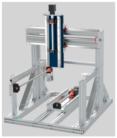
Figure 3.
Model of the proposed six-axis HMT frame with the X, Y, Z linear axes and the ATC motion subsystems.
Table 3.
Material properties of candidate structural machine members [56].
Table 3.
Material properties of candidate structural machine members [56].
| Material | Density ρ g/cm3 | Tensile Yield Strength σ (MPa) | Modulus of Elasticity E (GPa) | Ult Tensile Strength σmax (MPa) | Shear Modulus Sy (GPa) | Specific Tensile modulus E/ρ | Specific Tensile Strength Sy/ρ | Cost (US$/kg) |
|---|---|---|---|---|---|---|---|---|
| Al 6061 -T5 | 2.7 | 185 | 69 | 310 | 2.56 | 25.50 | 9.63 | 2.30–3.50 |
| Steel A36 | 7.85 | 250 | 200 | 550 | 79.3 | 25.47 | 10.1 | 0.55–0.68 |
| PC | 1.22 | 62.05 | 3.1 | 65.5 | 5.03 | 2.54 | 4.12 | 3–6 |
4.2. Electromechanical Systems
The motion subsystems of an HMT help perform its basic operations, which are 3D printing and/or machining of parts. These subsystems have direct impact on performance, accuracy, repeatability, longevity and ultimately mechanical vibrations transferred to the part, which directly affect its quality. They consist of the drive system, the power transmission and guiding/sliding system, each directly affecting these properties on the HMT. Next, we present the reasoning and analysis for their choice in the proposed HMS, based on their advantages and disadvantages.
4.2.1. Drive Systems and Motors for HMTs
A feed drive system moves an axis to the desired positions in a machine tool. There are two main types of feed drive systems: (a) direct and (b) indirect. In the direct drive system (Figure 4a), a linear motor moves the axis using a magnetic field or compressed air. Although the magnetic variation provides high speeds and accelerations, during machining the maximum acceleration and loading capacity are severely limited due to cutting forces. The pneumatic feed drives operate similarly, converting the energy of compressed air into linear or rotational motion. Direct drives seem a very good alternative for quick and direct axis movement for AM processes, where the applied external forces are small as there is no mechanical contact between the tool and the part. However, its use in an HMT would mean that this would also operate for cutting operations, and thus working conditions would be far from preferable, risking mechanical machine failure. Additionally, direct drive systems are costly, in a magnitude of few thousand € per unit, and their operation and control are complex, resulting in a significant increase in the proposed machine costs, which are intended to be kept low.
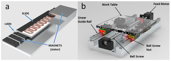
Figure 4.
(a) Direct feed drive system (linear motor) [57]. (b) Indirect feed drive consisting of motor, coupler, ball screw and its supports, nut, nut housing, linear guides and blocks. Blocks and nut/nut housing are held together by a common mounting plate.
On the other hand, in the indirect drive system (Figure 4b), a rotary motor moves the axis through a system that includes a screw and nut system. The rotational motion of the motor is transferred to a rotating screw through a coupler, which in turn is translated into a linear motion of a nut, usually with recirculating balls for eliminating friction and wear between the screw and nut. There are two candidate electric rotary motor types that can be used to drive the axes of the proposed machine tool, keeping in mind the low cost and the high precision: (a) servomotors and (b) stepper motors, both of which have their own strengths and weaknesses. While servomotors have a feedback drive system, stepper motors have multiple methods to be driven. Although both are similar in terms of control, there are major differences in performance and applications. Table 4 provides an abstract performance comparison of the two motor types [58]. Indirect drive systems show high rigidity of the system against the developing forces during machining process. Although this mechanism has limited speed and acceleration ability, the mechanism retains its acceleration ability for a wide range of inertia variations. The high efficiency load capacity, the long shift path and the low heat dissipation of the systems in combination with their long life facilitate the wide application of the system in the machine tool industry [59,60,61,62].
Table 4.
Servo versus typical stepper motors [63].
Although several actuators have been used for CNC machine tools in the past, including hydraulic actuators, which are mainly used for very high powers and large machine tools, electric motors are the most common for axes’ drive in small and medium-sized CNC machine tools. The proposed HMT is small in size, so hydraulic actuators cannot and need not be utilized, as the power and torque provided by small-size modern electric motors have been proven to be enough in soft material machining operations.
During recent years, motor manufacturers have developed closed-loop stepper motors with embedded rotary encoders which simulate the operation of servo motors very closely at a cost near that of the open-loop stepper motor. The local closed-loop system handles pulses sent to the stepper motor, thus eliminating the possibility of the stepper motor losing steps during operation, even above torque limits, by locally retrying to feed the pulses for a limited number of times, e.g., three times, before stopping and flagging an error. However, closed-loop stepper motors cannot feed their status to an overall machine closed-loop system. Thus, this type of stepper motor is a really good choice whenever low-cost controlled motion is required. They can be used in applications where you need to control rotation angle, position and synchronization. Due to the inherent advantages mentioned in Table 4 and above, these have found many applications, including CNC routers, printers, laser cutters, engravers and others. Their features make them the best choice for a wide range of applications, mainly in measurement and control, as they are low cost, produce high torque at low revolutions and possess a simple structure [64,65]. There are several factors to consider when choosing a stepper motor [66,67,68], such as starting torque, maximum speed, duty cycle, required power, load inertial, speed control, reversible motor, time to accelerate and to decelerate, size and weight.
4.2.2. Power Transmission Mechanism
A power transmission mechanism transforms the power of an electric motor to the linear push/movement of the machine axes. Although there are a few mechanisms that perform that, such as rack and pinion, gears, pulleys and belts and their variations, the most common one in machine tools is screw and nut. There are two main screw types: (a) power screw and (b) ball screw (Figure 5). They differ in power transfer efficiency, friction power losses and the respective thermal phenomena, accuracy and backlash elimination, permissible rotational and required linear speeds.
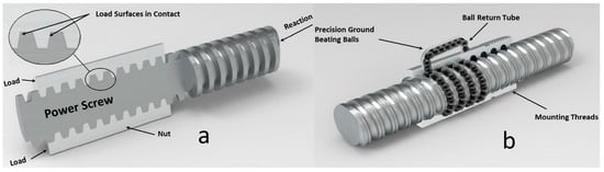
Figure 5.
(a) Power screw (trapezoidal), (b) ball screw.
Power screws have trapezoidal threads. As the motor rotates, the thread pushes the nut forward or backward depending on the direction of rotation. This transforms the motor’s rotary motion to be linear on the axis. Ball screws provide many advantages in their applications. Although the basic screw and nut principle applies, contact between them is achieved though recirculating balls. With the right nut material, ball screws can achieve self-lubrication. For example, in low load applications, polymer nuts such as acetal are used. This reduces or even eliminates the need for lubrication. On the contrary, metal nuts can carry higher loads, but they will also have a higher friction force and require lubrication [69]. Table 5 shows the advantages and disadvantages of these two power transmission screw types [70,71,72].
Table 5.
Advantages and disadvantages of power transmission screws [73].
CNC machine tools use both power and ball screws. Low-cost machines use power screws for cost-saving and design simplicity reasons. However, as speeds increase and high reliability requirements are set, power screws become the proper solution. The choice must be weighed against capabilities and costs to determine the optimal drive mechanism for the system. For the proposed HMT, ball screws were chosen for all linear axes, mainly for efficiency and accuracy reasons (see Figure 5b).
4.2.3. Hollow Rotary Table
A hollow rotary table (Figure 6) is a rotary load device [74,75]. It uses spiral conical gears whose contact teeth design offer uniform loading, thus, high torque and high transmission efficiency, high accuracy and high-cost efficiency. Combined with a planetary reducer, the transmission ratio reaches 1:180. Mounting accuracy is comparable to the direct drive motor which can carry the idle load in a short time. A cross-roller bearing is used in the hollow table, which allows both high load and high rigidity. Tables and arms can be installed directly on the output table. This saves design time and construction cost of an installation mechanism, the installation of necessary mechanism components, voltage adjustment of a belt, etc., when mechanical components such as the belt and pulley are used for installation. The large diameter of the output table hole helps reduce the complexity of wiring and piping, thus simplifying the design of equipment. Hollow rotary tables were chosen for the B and C rotary axes because of their high torque output (see Figure 7b).
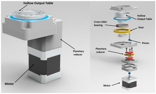
Figure 6.
The designed hollow rotary table for the HMT.
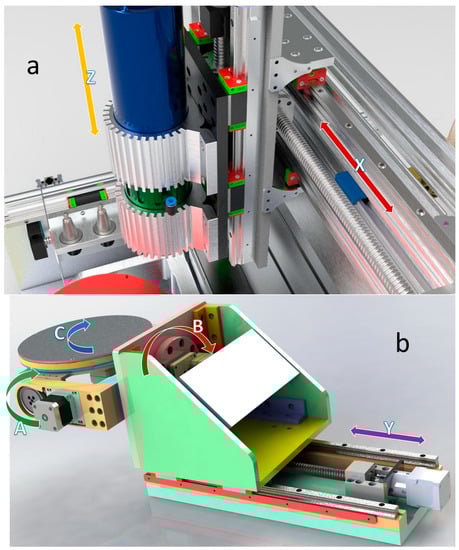
Figure 7.
(a) X and Z linear axes, and (b) the three rotary axes (A, B and C) and Y linear axis of the modeled HMT, including linear guides, blocks, ballscrews, ballscrew nuts and supports, motors, couplers and mounting plates, which formulate the mechanical motion and rotational systems.
4.2.4. Linear Guide System Design
Linear guide systems, consisting of rails and blocks, provide load support and balancing for the linear axes. These are used for the linear X, Y and Z axes (Figure 6) [76]. These systems are capable of higher loading capacities with stability when handling balanced and unbalanced loads in any orientation, maintaining approximately the same load capacity due to high rigidity. Thus, these apply perfectly in the designed HMT. Incorrect linear guidance often comes from design miscalculations in loads and speeds [77,78,79]. Linear guide rails were originally designed for the CNC machine tool and automation industry and they replaced the built-in guides that were integral in the machine tool frame/body in older machine tools. Linear guide rails are more rigid and stiffer, but they need constant support with strict requirements for flatness and parallelism. Their main advantage is high placement accuracy, even for high loads [80].
Figure 7 presents two main subsystems of the proposed HMT; specifically, Figure 7a presents the linear axes X and Z with the mounted spindle, whereas Figure 7b illustrates linear axis Y and the rotary axes A, B and C. Both these main subsystems of the HMT are mounted on the machine tool frame, as depicted in Figure 3, where only the linear axes X, Y and Z appear.
4.2.5. Automatic Tool Changing System
One of the most important issues that arose during the design of the proposed HMT was to determine how to both rotate the cutting tool shaft and adapt the extruder mechanism without an unnecessary increase in machine complexity. The idea is to change the cutting tool and extrusion head automatically, thus saving operation time and minimizing human intervention. This was achieved by mounting the extruder to a tool holder and using a slip ring for electrical connection (see Figure 8).
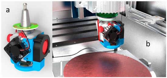
Figure 8.
(a) 3D model of the newly designed 3D printing extruder head installed on a tool holder. The slip ring (light green) provides the extruder head’s electrical connection. (b) The 3D printing extruder positioned in the spindle (3D CAD model), ready for performing multi-axis extrusion 3D printing inside the proposed six-axis HMT.
4.3. Proposed HMT Specifications and Digital Assembly
All design considerations regarding the HMT operation and subsystems, which were previously presented and discussed, led to the formulation of all HMT specifications and can be cumulatively seen in Table 6. The digital assembly of the proposed HMT is depicted in Figure 9.
Table 6.
Specifications of the proposed six-axis HMT.
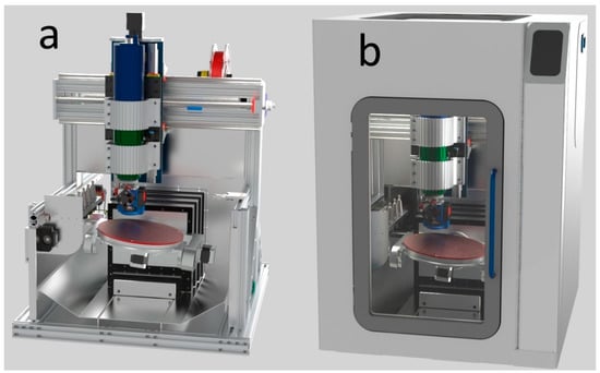
Figure 9.
3D model of the proposed desktop multi-axis hybrid milling-filament extrusion CNC machine tool (a) without covers, (b) with covers and external features.
5. Load Modeling of the Designed HMT
As described in the previous sections, HMTs are machines that perform both SM and AM processes. However, in terms of mechanical loading, the SM processes such as milling and drilling are the ones that load an HMT significantly, as compared to the AM ones, whose main loading is thermal. When cutting tools are involved, cutting forces can affect both the part processing and the structure of the machine tool itself. Cutting tools in CNC machining are used for removing large quantities of material during the roughing phase and for providing the necessary surface smoothness as well as for perfecting the geometric features of a workpiece during the finishing phase. Vibrations that appear during these phases are determined by machine tool stiffness and strength, so they must be taken into account at the machine design stage. Unwanted vibrations (chattering) between tool and workpiece also affect the quality of the final surface during finishing. Chatter is one of the most critical features considered during the design process of a machine [81,82,83]. Static and dynamic deformations of the machine tool play an important role in the integrity of tolerance and stability during the machining process that affect workpiece quality and machine productivity and accelerate tool wear.
Modal analysis is the study performed for analyzing a structure under vibration conditions. The behavior of the structure in a given frequency range can be modeled as a set of individual vibration modes. For any structural vibration problem, eigen-values must be identified and quantified. Some parameters, such as natural frequency and resonant frequency, are used to describe this effect. From the use of modal parameters to model the problem, natural frequencies that cause a structure’s maximum deformations can be examined, leading to improvement of the machine design. Modal analysis is one of the main tools for analyzing the dynamic behavior of structures, thus optimizing the design of structural elements that a machine comprises [84,85].
In order to evaluate structural performance of the proposed HMT, Finite Element Analysis (FEA) was used to model static and dynamic behaviors under different loading conditions. FEA is based on meshing the studied structure. Creating a proper mesh is important for the accuracy of the results. Due to machine tool structural complexity, a simplified FE design model was created by combining structured and unstructured meshes. After meshing, the total number of elements generated was 455,224 and the respective number of nodes was 659,338. As far as the used boundary conditions are concerned, all beams at the base of the machine tool are fixed, i.e., all respective degrees of freedom are set to zero (Figure 10). Model loads are mechanical loads: part weight, tool and spindle weight and cutting forces in various table angular positions (A and B directions) under the influence of gravity. Axis C does not affect the analysis and does not change the obtained results, and this is why it is not included as a parameter taking various values. Moreover, in the global coordinate system, the nodes where loads are applied are specific, regardless of the table angle around the global Z axis. Figure 10 shows the complete mesh of the simplified structure for the proposed machine for analysis. The simplified machine model combines structured (rotating symmetrical parts) and unstructured elements (aluminum profiles). Adjacent joints have been achieved by merging selected nodes, by inserting a rigid connection (replacing screw connections) or by integrating linear springs between corresponding pairs of nodes (connection between linear guides and carriages or their drive screws).
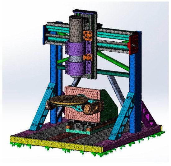
Figure 10.
FEM mesh of the proposed six-axis HMT.
Performed FE analyses and respective loading scenarios were as follows:
- Static analysis under gravity forces, without external load.
- Static analysis under gravity, external force of 100 N (part weight) applied to the table and external force 50 N applied to the spindle tip in the Z direction (tool weight).
- Static analysis under gravity force, external force of 100 N (part weight) applied to the table and external forces of 100 N applied to the table in X, Y and Z directions simultaneously simulating cutting forces at different table angular positions in A and B directions.
- Frequency analysis and harmonic analysis for the dynamic response to natural frequencies, as well as to vibrational forces created during cutting.
6. Results
6.1. Static Analysis
The static analysis shows the behavior of the structure under constant loads. From static analysis, structure deformations and stresses were obtained. The structure was examined in two different cutting conditions; the first is cutting forces during simultaneous three-axis machining and the second is during drilling. Table 7 and Table 8 present the static analysis results.
Table 7.
Static analysis results for endmill cutting forces in X, Y and Z directions simultaneously.
Table 8.
Static analysis results for drilling cutting forces in Z direction.
After the simplification of the machine tool structure, the total machine weight was 20 kg. Thus, the entire deformation of the Z-axis beam was evaluated. Deformation in the most critical areas of the machine tool when stationary without any external loads was under 0.1 μm in the X-axis beam with the spindle in the middle of the X axis and under 0.2 μm in the support beam of the B axis, which holds the table and A and C axis subsystems. Thus, the overall deformation under the machine’s own weight is very low and considered negligible, as it does not affect the accuracy of the machine tool. To investigate deformation caused by the cutting force, spindle specifications must be undertaken; the selected spindle had a torque of 0.35 Nm, 1.1 kW of power and a maximum rotation speed of 24,000 rpm. Axial momentum load applied to the tip of the spindle that bears an 8 mm diameter end-mill was T = 0.35 Nm, and the force load of F = 100 N in all X, Y and Z directions and at the same time for the most unfavorable angle of the table (for A and B rotation angle of 45°). These loads are the maximum applicable ones for the specific machine design. Table 7 shows results from the static analysis, showing that the maximum deformations are of the order of 0.24 mm for the worst-case scenario at the brim of the table, which is too small to affect the actual cutting accuracy (Figure 11). Since the machine tool is designed to process only soft material, it is almost unlikely that forces of this order will develop, which makes the machine tool rigid enough within the specified operational values.
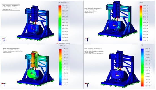
Figure 11.
Static analysis results for table angles A 45° and B 45°. Upper left is von Mises criterion (blue is 7.583 and red 1.308 × 10⁻⁷ N/m2), lower left is displacement in mm (blue is 0, red is 2.39 × 10⁻¹ mm), upper right is equivalent strain (blue is 10−10, red is 8.000 × 10⁻⁵) and lower right is Factor of Safety (FoS) (red is 11, blue is 35).
6.2. Frequency Response Functions
Dynamic behavior reflects the structure’s resistance to vibration. Therefore, a dynamic analysis was performed to determine the natural fundamental frequencies which are predicted for the machine tool model (Figure 12, Figure 13 and Figure 14). Natural frequencies indicate the dynamic characteristic of the joint, as this is one of the key factors influencing the dynamic performance of the machine tool. Accurate calculation of the stiffness parameters in the joints during the machine tool design stage is crucial for obtaining correct results in the theoretical analysis. Table 9 lists the first twelve critical eigenfrequencies of the structure. The rest are neglected, as the maximum spindle speed is 24,000 rpm.
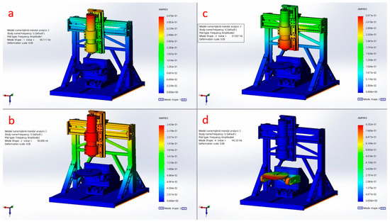
Figure 12.
Natural frequencies 1 to 4 at: (a) 50.111 Hz, (b) 58.505 Hz, (c) 81.507 Hz, (d) 142.330 Hz. Color coding: blue is 0.000 in all (a–d), red is in (a) 3.875 × 10⁻¹, (b) 2.420 × 10⁻¹, (c) 3.071 × 10⁻¹ and (d) 8.252 × 10⁻¹.
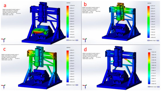
Figure 13.
Natural frequencies 5 to 8 at: (a) 152.160 Hz, (b) 187.660 Hz, (c) 245.790 Hz, (d) 317.250 Hz. Color coding: blue is 0.000 in all (a–d), red is in (a) 1.070, (b) 5.340 × 10⁻¹, (c) 4.297 × 10⁻¹ and (d) 1.833.
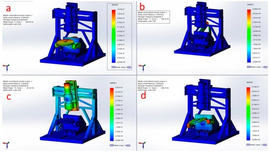
Figure 14.
Natural frequencies 9 to 12 at: (a) 346.350 Hz, (b) 351.320 Hz, (c) 359.760 Hz, (d) 390.230 Hz. Color coding: blue is 0.000 in all (a–d), red is in (a) 7.670 × 10⁻¹, (b) 5.031 × 10⁻¹, (c) 4.009 and (d) 9.190 × 10⁻¹.
Table 9.
Natural frequencies, corresponding spindle speeds, deformations and their effect on designed machine subsystems.
The first three critical frequencies appear at 50.111 Hz, 58.505 Hz and 81.507 Hz, which are observed in the lower section of the spindle, supported by the vertical columns in the X-Z plane. The fourth and fifth critical frequencies at 142.330 Hz and 152.165 Hz, respectively, are observed in the outer rim of the table. The sixth and seventh critical frequencies occur at 187.660 Hz and 245.790 Hz and are observed at the spindle, associated with the vertical column around the vertical Z axis. The eighth critical frequency is displayed at 317.250 Hz with a displacement of 1.833 mm, observed at the inclined supports of the machine back. The ninth critical frequency is displayed at 346.35 Hz with a displacement of 0.0767 mm in the arms of the machine table. Subsequent frequencies cannot be considered critical, as they lie outside the operating range of the machine tool. In all, deformations are very small and do not affect the machining accuracy; at the same time the frequencies can be avoided if the operating spindle speeds do not match them, thus avoiding unfavorable operating conditions. Table 9 also lists how the natural frequencies affect the machine structure.
6.3. Harmonic Response Analysis
The machine assembly model was subjected to dynamic loads, which simulate the actual machining process, and thus the behavior of the structure under varying loads was examined. Dynamic analysis was performed by subjecting the structure to cyclic (harmonic) loading, resembling processing conditions. It was examined whether the harmonic frequency is identical to the natural frequency of the structure to avoid resonance of the structure to the maximum allowable amplitude. Resonance should be avoided as maximum vibrations can lead to excessive stresses or in extreme cases damage (failure) of the structure. The structure was analyzed using FE for harmonic response analysis. Loads were applied according to design requirements, as seen in Section 5. Cutting conditions refer to loads for pocket machining with D = 8 mm (tool diameter), Nz = 2 (number of flutes), λs = 30o (helix angle), fz = 0.05 mm/tooth (feed per tooth per revolution), ap = 2 mm (axial depth of cut), ae = 2 mm (radial depth of cut) and n = 3600 rpm (revolutions per minute). The above process parameters and cutting model were obtained by references [86,87,88,89]. However, since rotational velocities in these were small for the combination of the designed spindle and the part material, they were doubled in the analysis. Results show that the proposed machine structure is able to withstand the harmonic load in resonance frequencies. Therefore, the proposed machine design is considered to be safe from harmonic loading, as the obtained values from the analysis are very small and the FOS for all studied scenarios is between 17 and 22, far exceeding the level of safety stated in the relevant literature. Table 10 and Figure 15 show the results of harmonic analysis.
Table 10.
Harmonic analysis results when applying three-dimensional cutting (simultaneous movement in X, Y and Z directions) with an end-mill cutter with the above process parameters.
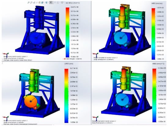
Figure 15.
Harmonic analysis results for table angle A 45° and B 45°. Upper left is von Mises criterion (blue is 5.264 and red 6.447 × 10⁶ N/m2), lower left is displacement in mm (blue is 0, red is 3.211 × 10⁻² mm), upper right is displacement velocity in mm/s (blue is 0, red is 1.537 × 10⁻² mm/s) and lower right is displacement acceleration in mm/s2 (blue is 0, red is 3.236 mm/s2).
After identifying the natural frequencies and their vibration modes, harmonic response analyses were performed to quantify the steady state response of the machine to loads that vary harmoniously with time. In addition, nonlinear parameters, such as damping, were applied to the spindle tip and responses were evaluated for different eigenfrequencies. Harmonic response analysis is able to verify whether the behavior of the structure is able to successfully overcome resonance and the harmful effects of self-excited forced vibrations. The equivalent forces predicted by the load modeling were converted to a harmonic form applied to the machine. Maximum deformation observed at the brim of the machine tool table (angles A 45°–B 0°) during vibration was 0.06 mm. The results of the dynamic analysis and evaluations of the structure are acceptable and well within intended operating limits.
7. Discussion
Static and dynamic analysis results of Section 6 showed that the proposed six-axis HMT design has the required strength and demonstrates the required dynamic behavior to fulfil its purpose, which is to additively and subtractively manufacture parts made from polymers and other non-metallic materials. Novelty in the machine design lies in the fact that a similar low-cost industrial-grade multi-axis machine tool for both CNC milling and extrusion 3D printing has not appeared in the literature or in the market. A few robotic systems have been found in the literature that can perform HM by exchanging end effectors, such as in [41]. However, it is well known that these kinds of robotic systems are costly in acquisition, maintenance and utilization, multiple times over the cost of the proposed machine tool, as seen in Table 6, and they generally lack in rigidity during subtractive operations due to the cutting forces causing vibrations. Thus, robotic HM is limited in terms of production speed when compared to cartesian-type structured HMTs, such as the one proposed. Cumulatively, the properties that make this machine tool novel are:
- High precision industrial six-axis CNC milling and six-axis extrusion 3D printing.
- Multiple material processing.
- Automatic Tool Changer for both additive and subtractive heads/tools with common mechanical interface.
- Slip ring for electrical connection of extrusion 3D printing heads.
- Closed and controlled work environment.
- Low-cost structure respective to the precision class.
The significance of the current machine design and modeling study is the first step of the chain in developing a new machine tool that potentially can revolutionize the way that multi-material high complexity industrial grade parts are manufactured with reduced costs. Based on the analysis results, an HMT prototype will be built after the completion of the presented design study. With the completion of the prototype, it will be benchmarked against process parameters and cutting force profiles found in the literature and the numerical results obtained in this study. The main production focus of the machine tool is the multi-material and multi-functional parts for the aerospace and general engineering sectors, as well as for embedded high-complexity electronic systems and for biomedical devices with embedded electronics. Multi-material will be handled through multiple additive heads, while part accuracy and surface quality will be achieved through the machining heads. The following process sequencing examples demonstrate the way that this machine is able to produce finalized parts for these high-added value sectors:
- (i)
- Lab-on-a-chip devices. Orient the table properly, usually facing upwards or with a small tilt angle, when the first additive stage starts. Start extrusion 3D printing with one material, part or substrate/support structure. Substrate could be preset on the table. If using a substrate, automatically change tool to a milling cutter to level or formulate the surface of the substrate. Change to 3D printing head with part material. After n steps of 3D printing, change to cutting tool for face and shoulder milling. If part is not planar, apply multi-axis machining accordingly. Change tool to micro-milling tool and cut or clean up channels and micro-features in two or three dimensions. Clean up chips using compressed air. Change tool to 3D printing head with channel fill-up material (could be the same as the substrate or another, e.g., a low temperature wax). Change tool to face or to smooth part surface and clean up chips using compressed air. Change tool to extrusion 3D printing head with the same or different part material. Continue 3D printing for more m steps. Repeat previous actions as needed, based on part geometry. When finished 3D printing, change to cutting tool and finish off outer part surfaces. Filters (HEPA) and disinfecting devices (UV lamp) can be continuously on/off during the production cycle or on and off, as seen fit by the operator. Remove part from table. Clean up substrate mechanically or thermally and thermally remove fill-up material from inside the channels.
- (ii)
- Embedded electronic devices. As in the previous example, the part can be built directly on the table or on a substrate, which is either preset on the table or 3D printed with an extrusion 3D printing head and then formulated with a milling tool. Interchange conductive and isolating material extrusion 3D printing heads for n layers, whether planar or free-form. Change to milling tools for cleaning up, leveling, or smoothing when needed, even when changing from isolating material extrusion head to conductive material extrusion head. Always use compressed air to remove chips from part surface after milling. Repeat these actions as needed to finish the part. Use milling tools to cut off isolating material and make room for devices, such as resistors, capacitors, inductors, transistors, etc. Carefully place the devices by hand or by using a pick-and-place robotic arm synchronized with the machine. Fill up the cavity with isolating material with extrusion head. When part is built, use a milling tool to finish off outer part surfaces and blow off any chips with compressed air.
- (iii)
- Multi-material and multi-functional parts. Use a pre-loaded or an empty table. Rotate table upwards and start by using an extrusion head to apply material. Before any extrusion 3D printing stage, use milling tool to flatten or smoothen the surface and post-processing for optimum layer bonding results and part integrity. Change extrusion heads either between layers or different sections of a layer. Special heads can offer on-line mixing of multiple materials for varying concentrations along planar or curved layers. Between 3D printing stages, CNC cutting stages can be used for creating features or for making space for installing electronic or mechanical parts and sensors.
8. Conclusions and Further Work
In recent years, the increased need for parts with complex, intricate and high surface quality parts at a reduced cost has led to ongoing research and development of Hybrid Manufacturing Machine Tools, which are seamlessly combining CNC machine tools and 3D printer operations in a single work environment. These Hybrid Machine Tools need to be rigid, durable and precise to minimize processing times, material waste during subtractive processing, post-processing by hand or on other equipment and all related costs. However, they are mainly utilized in either heavy industry equipment of extremely high acquisition, production and maintenance costs or home (non-professional) equipment with low processing repeatability and part quality. Although the implementation of Hybrid Manufacturing processes has proven to be quite efficient in producing commercially ready parts that require no or minimal post-processing, there is not yet an appropriate machine tool in the market which is efficient, cost-effective and capable of producing quality parts. The very high acquisition and production cost of industrial hybrid machine tools, however, is not in line with everyday industrial, biomedical or artisanal practice of producing small batches of limited-cost pieces from non-metallic materials.
This study aims to address the gap in the hybrid manufacturing sector by presenting design and structural analysis of a new desktop multi-axis hybrid machine tool that creates finished products made of polymers, elastomers and special type composites. The machine combines six-axis Subtractive Manufacturing as a multi-axis CNC milling center with six-axis Additive Manufacturing, specifically Fused Filament Fabrication 3D printing technology with an automated tool change system. The structural elements as well as the moving and rotating elements that comprise the machine were designed and selected with the aim of simplifying their production and the machine assembly so that the total production cost of the machine remains low. The performed static and dynamic Finite Element Analyses indicate that the behavior of the proposed structure is rigid and stiff enough for cutting soft materials, thus making it a viable and low-cost professional solution for small batch manufacturing of polymer, elastomer or special composite products that need no further post-processing. In static analysis, even when applying a 100 N three-dimensional force at the tip of the table holding a 100 N part, the table rim displacement is less that 0.24 mm. Natural frequency analysis showed that the back strut of the machine can reach 4 mm compressive deformation when the spindle operates at 21,585.60 rpm, so this should be avoided unless it is more supported. However, Harmonic Response Analysis proved that maximum deformation is lower than 0.06 mm during operation, which is an excellent result for the proposed low-cost HMT structure. This study presents the rationale and the systematic method of designing the machine tool and choosing proper components/subsystems based on set specifications which are imposed by high-added value parts.
Further work includes the realization of the prototype and assessing the proposed machine tool efficiency in creating finalized components for engineering and biomedical applications such as small compressors and low temperature turbines, microfluidic devices, dental tools and embedded electronic devices.
Author Contributions
A.A.K.: conceptualization, methodology, writing—original draft, review and editing, supervision, revision. D.M.I.: investigation, formal analysis, visualization, writing—original draft. All authors have read and agreed to the published version of the manuscript.
Funding
This research received no external funding.
Data Availability Statement
Data is contained within the article.
Conflicts of Interest
The authors declare no conflict of interest.
References
- García Nieto, P.J.; García-Gonzalo, E.; Ordóñez Galán, C.; Bernardo Sánchez, A. Hybrid ABC Optimized MARS-Based Modeling of the Milling Tool Wear from Milling Run Experimental Data. Materials 2016, 9, 82. [Google Scholar] [CrossRef] [PubMed]
- Merklein, M.; Junker, D.; Schaub, A.; Neubauer, F. Hybrid additive manufacturing technologies—An analysis regarding potentials and applications. Phys. Procedia 2016, 83, 549–559. [Google Scholar] [CrossRef]
- Jones, J.B. The Synergies of Hybridizing CNC and Additive Manufacturing; Hybrid Manufacturing Technologies Ltd.: Mckinney, TX, USA, 2016. [Google Scholar]
- Ngo, T.D.; Kashani, A.; Imbalzano, G.; Nguyen, K.T.Q.; Hui, D. Additive manufacturing (3D printing): A review of materials, methods, applications and challenges. Compos. Part B Eng. 2018, 143, 172–196. [Google Scholar] [CrossRef]
- Newman, S.T.; Zhu, Z.; Dhokia, V.; Shokrani, A. Process planning for additive and subtractive manufacturing technologies. CIRP Ann. Manuf. Technol. 2015, 64, 467–470. [Google Scholar] [CrossRef]
- Yamazaki, T. Development of A Hybrid Multi-tasking Machine Tool: Integration of Additive Manufacturing Technology with CNC Machining. Procedia CIRP 2016, 42, 81–86. [Google Scholar] [CrossRef]
- Müller, M.; Wings, E. An Architecture for Hybrid Manufacturing Combining 3D Printing and CNC Machining. Int. J. Manuf. Eng. 2016, 2016, 8609108. [Google Scholar] [CrossRef]
- Suh, J.D.; Lee, D.G. Design and manufacture of hybrid polymer concrete bed for high-speed CNC milling machine. Int. J. Mech. Mater. Des. 2008, 4, 113–121. [Google Scholar] [CrossRef]
- Chen, T.C.; Chen, Y.J.; Hung, M.H.; Hung, J.P. Design analysis of machine tool structure with artificial granite material. Adv. Mech. Eng. 2016, 8, 1687814016656533. [Google Scholar] [CrossRef]
- Rajurkar, K.P.; Zhu, D.; McGeough, J.A.; Kozak, J.; De Silva, A. New Developments in Electro-Chemical Machining. CIRP Ann. 1999, 48, 567–579. [Google Scholar] [CrossRef]
- Kozak, J.; Rajurkar, K.P. Hybrid machining process evaluation and development. In Proceedings of the 2nd International Conference on Machining and Measurements of Sculptured Surfaces, Krakow, Poland, 20–22 September 2000; Keynote paper. The Institute of Metal Cutting (IOS): Krakow, Poland; pp. 501–536. [Google Scholar]
- Aspinwall, D.K.; Dewes, R.C.; Burrows, J.M.; Paul, M.A. Hybrid High Speed Machining (HSM): System Design and Experimental Results for Grinding/HSM and EDM/HSM. CIRP Ann. 2001, 50, 145–148. [Google Scholar] [CrossRef]
- Nau, B.; Roderburg, A.; Klocke, F. Ramp-up of hybrid manufacturing technologies. CIRP J. Manuf. Sci. Technol. 2011, 4, 313–316. [Google Scholar] [CrossRef]
- Fessler, J.R.; Merz, R.; Nickel, A.H.; Prinz, F.B.; Weiss, L.E. Laser Deposition of Metals for Shape Deposition Manufacturing. 1996 International Solid Freeform Fabrication Symposium. Available online: https://repositories.lib.utexas.edu/handle/2152/69928 (accessed on 12 September 2022).
- Klocke, F.; Wirtz, H.; Meiners, W. Direct Manufacturing of Metal Prototypes and Prototype Tools. 1996 International Solid Freeform Fabrication Symposium. Available online: https://repositories.lib.utexas.edu/handle/2152/69931 (accessed on 3 January 2022).
- Kerschbaumer, M.; Ernst, G. Hybrid manufacturing process for rapid high performance tooling combining high speed milling and laser cladding. In Proceedings of the ICALEO 2004—23rd International Congress on Applications of Lasers & Electro-Optics, San Francisco, CA, USA, 4 October 2004. [Google Scholar] [CrossRef]
- Sreenathbabu, A.; Karunakaran, K.P.; Amarnath, C. Statistical process design for hybrid adaptive layer manufacturing. Rapid Prototyp. J. 2005, 11, 235–248. [Google Scholar] [CrossRef]
- Song, Y.A.; Park, S.; Choi, D.; Jee, H. 3D welding and milling: Part I—A direct approach for freeform fabrication of metallic prototypes. Int. J. Mach. Tools Manuf. 2005, 45, 1057–1062. [Google Scholar] [CrossRef]
- Kovacevic, R.; Valant, M.E. System and Method for Fabricating or Repairing a Part. US Patent 2006. Available online: https://patents.google.com/patent/US7020539B1/en (accessed on 3 March 2022).
- Xinhong, X.; Haiou, Z.; Guilan, W.; Guoxian, W. Hybrid plasma deposition and milling for an aeroengine double helix integral impeller made of superalloy. Robot. CIM 2010, 26, 291–295. [Google Scholar] [CrossRef]
- DMG Mori. Lasertec 65 DED Hybrid. Available online: https://us.dmgmori.com/products/machines/additive-manufacturing/powder-nozzle/lasertec-65-ded-hybrid (accessed on 21 September 2022).
- Manogharan, G.; Wysk, R.; Harrysson, O.; Aman, R. AIMS—A Metal Additive-hybrid Manufacturing System: System Architecture and Attributes. Procedia Manuf. 2015, 1, 273–286. [Google Scholar] [CrossRef]
- Ahn, D.G. Applications of laser assisted metal rapid tooling process to manufacture of molding & forming tools—State of the art. Int. J. Precis. Eng. Manuf. 2011, 12, 925–938. [Google Scholar] [CrossRef]
- 5AXISMAKER. 5-Axis CNC Mill/3D Printer. Available online: https://5axismaker.co.uk/5xm-overview (accessed on 5 July 2022).
- Creality. CP-01 3D Printer—Creality 3D. Available online: https://www.creality.com/products/creality-cp-01-3d-printer (accessed on 5 July 2022).
- XYZprinting. da Vinci 1.0 Pro. Available online: https://www.xyzprinting.com/en-US/product/da-vinci-pro (accessed on 6 July 2022).
- Sertoglou, K. Review: Snapmaker 2.0—3-in-1 3D Printer with CNC and Laser Capabilities. Available online: https://3dprintingindustry.com/news/review-snapmaker-2-0-3-in-1-3d-printer-with-cnc-and-laser-capabilities-192268/ (accessed on 6 July 2022).
- Jennings, A. SnapMaker 2.0 Review. Available online: https://www.techradar.com/reviews/snapmaker-20 (accessed on 6 July 2022).
- All3DP.PRO. ZMorph VX Review: Best 3-in-1 3D Printer 2020. Available online: https://all3dp.com/1/zmorph-vx-review-3d-printer-specs/ (accessed on 6 July 2022).
- Zmorph Fab. Available online: https://zmorph3d.com/products/zmorph-fab/ (accessed on 10 September 2022).
- Diabase Engineering. H5-400. Available online: https://www.diabasemachines.com/hseries (accessed on 12 September 2022).
- Grutle, Ø.K. 5-axis 3D Printer. Master’s Thesis, Universitetet I Oslo, Oslo, Norway, 2015. [Google Scholar]
- Flynn, J.M.; Shokrani, A.; Newman, S.T.; Dhokia, V. Hybrid additive and subtractive machine tools—Research and industrial developments. Int. J. Mach. Tools Manuf. 2016, 101, 79–101. [Google Scholar] [CrossRef]
- Chen, L.; Xu, K.; Tang, K. Optimized sequence planning for multi-axis hybrid machining of complex geometries. Comput. Graph. 2018, 70, 176–187. [Google Scholar] [CrossRef]
- Ren, L.; Sparks, T.; Ruan, J.; Liou, F. Integrated Process Planning for a Multiaxis Hybrid Manufacturing System. ASME. J. Manuf. Sci. Eng. 2010, 132, 021006. [Google Scholar] [CrossRef]
- Karunakaran, K.P.; Gupta, N.K.; Patel, A.K.; Rakeshkumar, K.; Ganesan, G.; Siddhartha; Sealy, M.; Bernard, A. Multi-Station Multi-Axis Hybrid Layered Manufacturing (MSMA-HLM). Manuf. Lett. 2022, 33, 630–639. [Google Scholar] [CrossRef]
- Zhang, K.; Zhang, W.; Ding, X. Multi-axis additive manufacturing process for continuous fibre reinforced composite parts. Procedia CIRP 2019, 85, 114–120. [Google Scholar] [CrossRef]
- Zhang, H.; Liu, T.; Lu, L.; Yao, X.; Li, S.; Yuan, S. Multi-axis Toolpath Planning for Extrusion-Based Polymer 3D Printing: Review and Prospective. In Proceedings of the 2021 7th International Conference on Control, Automation and Robotics (ICCAR), Singapore, 23–26 April 2021; pp. 402–406. [Google Scholar] [CrossRef]
- Li, L.; Haghighi, A.; Yang, Y. A novel 6-axis hybrid additive-subtractive manufacturing process: Design and case studies. J. Manuf. Process. 2018, 33, 150–160. [Google Scholar] [CrossRef]
- Lee, W.-C.; Wei, C.-C.; Chung, S.-C. Development of a hybrid rapid prototyping system using low-cost fused deposition modeling and five-axis machining. J. Mater. Process. Technol. 2014, 214, 2366–2374. [Google Scholar] [CrossRef]
- Keating, S.; Oxman, N. Compound fabrication: A multi-functional robotic platform for digital design and fabrication. Robot. Comput. Integr. Manuf. 2013, 29, 439–448. [Google Scholar] [CrossRef]
- Duarte, J.; Santo, I.E.; Monteiro, M.T.T.; Vaz, A.I.F. Curved layer path planning on a 5-axis 3D printer. Rapid Prototyp. J. 2022, 28, 629–636. [Google Scholar] [CrossRef]
- Hwang, J.D.; Yang, J.S.; Yun, S.H.; Jung, Y.G. Hybrid Technology using 3D Printing and 5-axis Machining for Development of Prototype of the Eccentric Drive System. J. Korean Soc. Manuf. Process Eng. 2016, 15, 38–45. [Google Scholar]
- Živanović, S.; Popović, M.; Vorkapić, N.; Pjević, M.; Slavković, N. An overview of rapid prototyping technologies using subtractive, additive and formative processes. FME Trans. 2020, 48, 246–253. [Google Scholar] [CrossRef]
- Nutma, M. 3 Types of Manufacturing—Additive, Subtractive, and Forming. TechZone 360o. Available online: https://www.techzone360.com/topics/techzone/articles/2019/09/09/443185-3-types-manufacturing-additive-subtractive-forming.htm (accessed on 21 December 2021).
- Jones, J. Use Hybrid AM to Produce Longer-Lasting Multi-Material Molds. MoldMaking Technology. Available online: https://www.moldmakingtechnology.com/articles/use-hybrid-am-to-produce-longer-lasting-multi-material-molds (accessed on 21 December 2021).
- Yao, X.; Moon, S.K.; Bi, G.; Wei, J. A multi-material part design framework in additive manufacturing. Int. J. Adv. Manuf. Technol. 2018, 99, 2111–2119. [Google Scholar] [CrossRef]
- Weflen, E. A Hybrid Additive and Subtractive Manufacturing Approach for Multi-Material Components. Master’s Dissertation, Iowa State University, Ames, IA, USA, 2020. [Google Scholar]
- Hanson, K. Machining for Dummies; John Wiley & Sons, Inc.: Hoboken, NJ, USA, 2017. [Google Scholar]
- Mein, S. What Is Hybrid Manufacturing? Fire Trace International. Available online: https://www.firetrace.com/fire-protection-blog/hybrid-manufacturing (accessed on 21 March 2022).
- Creative Mechanisms Staff. Additive Manufacturing vs. Subtractive Manufacturing. Creative Mechanisms. Available online: https://www.creativemechanisms.com/blog/additive-manufacturing-vs-subtractive-manufacturing (accessed on 21 December 2021).
- Martinov, G.M.; Obuhov, A.I.; Martinova, L.I.; Grigoriev, A.S. An approach to building specialized CNC systems for non-traditional processes. Procedia CIRP 2014, 14, 511–516. [Google Scholar] [CrossRef]
- Amanullah, A.N.M.; Murshiduzzaman; Saleh, T.; Khan, R. Design and Development of a Hybrid Machine Combining Rapid Prototyping and CNC Milling Operation. Procedia Eng. 2017, 184, 163–170. [Google Scholar] [CrossRef]
- Grzesik, W. Hybrid additive and subtractive manufacturing processes and systems: A review. J. Mach. Eng. 2018, 18, 5–24. [Google Scholar] [CrossRef]
- Ashby, M.F. Selection of Material and Shape, 4th ed.; Michael, F.A., Ed.; Butterworth—Heinemann, Elsevier: Oxford, UK, 2011. [Google Scholar]
- Navstar Steel Corporation. 6061 T6 Aluminium Plate. Available online: https://www.navstarsteel.com/6061-t6-aluminium-plate.html (accessed on 21 December 2021).
- HSmag. What Is a Linear Motor—Principle. Available online: https://www.hsmagnets.com/blog/linear-motor-principle/ (accessed on 26 December 2021).
- Stepper Online. Servo Motors vs. Stepper Motors. Available online: https://www.omc-stepperonline.com/support/servo-motors-vs-stepper-motors (accessed on 10 January 2022).
- NEPTEL. Module 4 Drives and Mechanisms—Lecture 1—Elements of CNC Machine Tools: Electric Motors. Available online: http://vtsnis.edu.rs/wp-content/plugins/vts-predmeti/uploads/CNC-motori.pdf (accessed on 10 January 2022).
- Cortina, M.; Arrizubieta, J.I.; Ruiz, J.E.; Ukar, E.; Lamikiz, A. Study of the porosity generated by the use of cutting fluid in hybrid processes combining machining and Laser Metal Deposition (LMD). Procedia CIRP 2018, 74, 733–737. [Google Scholar] [CrossRef]
- Yeung, C.H.; Altintas, Y.; Erkorkmaz, K. Virtual CNC system. Part I. System architecture. Int. J. Mach. Tools Manuf. 2006, 46, 1107–1123. [Google Scholar] [CrossRef]
- Hanifzadegan, M. Linear Parameter-Varying Control of Cnc Machine Tool Feed-Drives with Dynamic Variations. Ph.D. Dissertation, University of British Columbia, Vancouver, BC, Canada, 2014. [Google Scholar]
- ForumAutomation.com. Basics of Servo Motor, Its Advantages and Disadvantages. Available online: https://forumautomation.com/t/basics-of-servo-motor-its-advantages-and-disadvantages/3186 (accessed on 21 December 2021).
- Leger, G.; Choosing a Stepper Motor Power Supply. Simply Smarter Circuitry Blog. Available online: https://www.circuitspecialists.com/blog/stepper-motor-power-supplies/ (accessed on 26 March 2022).
- Gecko Drive Motor Controls. Stepper Motor Basics. Available online: https://www.geckodrive.com/support/step-motor-basics.html (accessed on 26 December 2021).
- AMCI. Stepper vs. Servo. Available online: https://www.amci.com/industrial-automation-resources/plc-automation-tutorials/stepper-vs-servo/ (accessed on 26 December 2021).
- Ramirez, F. Driving a Stepper Motor Based on the MC9S08QD4 and Other 8-Bit Families. Freescale Semiconductor, Inc. Available online: https://www.nxp.com/docs/en/application-note/AN3602.pdf (accessed on 26 March 2022).
- Collins, D. Stepper Motor Torque and Speed Characteristics Explained. Linear Motion Tips. Available online: https://www.linearmotiontips.com/stepper-motor-torque-speed-characteristics-explained/ (accessed on 26 December 2021).
- Morissette, A. Acme Screw vs. Ball Screw. Progressive Automations. Available online: https://www.progressiveautomations.com/blogs/how-to/acme-screw-ball-screw (accessed on 21 December 2021).
- Carvill, J. Mechanical Engineer’s Data Handbook; Butterworth-Heinemann: Oxford, UK, 1991. [Google Scholar]
- Childs, P.R.N. Mechanical Design: Theory and Applications; Butterworth-Heinemann: Oxford, UK, 2021. [Google Scholar]
- Moubarak, P.; Ben-Tzvi, P. Modular and reconfigurable mobile robotics. Rob. Auton. Syst. 2012, 60, 1648–1663. [Google Scholar] [CrossRef]
- Beardmore, R. Power Screws. Roymech. Available online: https://roymech.org/Useful_Tables/Cams_Springs/Power_Screws.html (accessed on 21 December 2021).
- JVL Intelligent Motors. HLMT—Rotary Actuators for ServoStep and MAC Motor. Available online: https://www.jvl.dk/1199/hlmt-rotary-actuator (accessed on 21 December 2021).
- Gigager. Product Catalogue—Hollow Rotary Table—SV Type for Servo Motor. Available online: https://5.imimg.com/data5/SB/YC/JZ/SELLER-2308089/gsn130-18k.pdf (accessed on 26 March 2022).
- HIWIN. HG Series—Heavy Load Ball Type Linear Guideway. Available online: https://motioncontrolsystems.hiwin.us/category/hg-series-heavy-load-ball-type-linear-guideway (accessed on 21 December 2021).
- Thomson. RoundRail Linear Guides and Components. Available online: https://www.thomsonlinear.com/downloads/bearings_guides/RoundRail_LinearGuides_Components_cten.pdf (accessed on 20 September 2022).
- Nippon Bearing. Basics of Linear Bearings. Available online: https://www.nbcorporation.com/basics-linear-bearings/ (accessed on 29 September 2022).
- NSK. Bearing Selection Guide. Available online: https://www.nsk.com/common/data/ctrgPdf/bearings/split/e1102/nsk_cat_e1102m_a7-141.pdf (accessed on 29 September 2022).
- StyleCNC. Round Guide Rails vs. Square Guide Rails for CNC Routers. Available online: https://www.stylecnc.com/user-manual/round-square-guide-rails-cnc-routers.html (accessed on 5 April 2022).
- Turkes, E.; Orak, S.; Neseli, S.; Yaldiz, S. Linear analysis of chatter vibration and stability for orthogonal cutting in turning. Int. J. Refract. Met. Hard Mater. 2011, 29, 163–169. [Google Scholar] [CrossRef]
- Turkes, E.; Orak, S.; Neseli, S.; Yaldiz, S. A new process damping model for chatter vibration. Meas. J. Int. Meas. Confed. 2011, 44, 1342–1348. [Google Scholar] [CrossRef]
- Turkes, E.; Orak, S.; Neseli, S.; Yaldiz, S. Decomposition of process damping ratios and verification of process damping model for chatter vibration. Meas. J. Int. Meas. Confed. 2012, 45, 1380–1386. [Google Scholar] [CrossRef]
- Vrtiel, Š.; Hajdu, Š.; Behúlová, M. Analysis of the machine frame stiffness using numerical simulation. IOP Conf. Ser. Mater. Sci. Eng. 2017, 266, 012015. [Google Scholar] [CrossRef]
- Max, A.; Hynek, M.; Řehounek, L. Dynamic analysis of CNC milling machine frame. In Proceedings of the 22nd International Conference Engineering Mechanics, Svratka, Czech Republic, 9–12 May 2016; pp. 9–12. [Google Scholar]
- Zhou, Z.; Xie, S.; Chen, D. Fundamentals of Digital Manufacturing Science; Springer: Berlin/Heidelberg, Germany, 2011. [Google Scholar]
- Sai, L.; Belguith, R.; Baili, M.; Dessein, G.; Bouzid, W. An approach to modeling the chip thickness and cutter workpiece engagement region in 3 and 5 axis ball end milling. J. Manuf. Process. 2018, 34, 7–17. [Google Scholar] [CrossRef]
- Mandrile, S.; Cazenave-Larroche, G.; Vernault, C.; Dessein, G.; Denape, J.; Paris, J.Y. Development of an in-house cutting forces simulation for fir tree broaching process. Int. J. Mach. Mach. Mater. 2014, 15, 18–35. [Google Scholar] [CrossRef]
- Chen, L.; Lau, T.Y.; Tang, K. Manufacturability analysis and process planning for additive and subtractive hybrid manufacturing of Quasi-rotational parts with columnar features. Comput. Aided Des. 2020, 118, 102759. [Google Scholar] [CrossRef]
Disclaimer/Publisher’s Note: The statements, opinions and data contained in all publications are solely those of the individual author(s) and contributor(s) and not of MDPI and/or the editor(s). MDPI and/or the editor(s) disclaim responsibility for any injury to people or property resulting from any ideas, methods, instructions or products referred to in the content. |
© 2023 by the authors. Licensee MDPI, Basel, Switzerland. This article is an open access article distributed under the terms and conditions of the Creative Commons Attribution (CC BY) license (https://creativecommons.org/licenses/by/4.0/).