Abstract
Torque sharing function (TSF)-based switched reluctance motor (SRM) control is an effective approach to minimize torque ripple and maximize efficiency. This study investigated the influence of the rotor geometry to overcome the inherent torque and current tracking error of used TSFs. Parameters of the TSF were optimized according to several objectives. A finite element method simulation model of the motor was built and verified to evaluate the objective functions. The optimization result is a set of functions that calculate optimal values of the start angle and overlap angle of the sinusoidal TSF for every operating point of the motor. Different objectives, including efficiency and a torque ripple, lead to different functions for calculating start and overlap angles. The research showed that if efficiency is the most important objective, it is possible to determine a suitable rotor pole geometry. For other criteria, the choice of rotor geometry is not so clear-cut and requires consideration of the SRM operating modes.
1. Introduction
The Switched Reluctance Motor (SRM) has simple mechanical construction but requires a designed and tuned controller for each specific application [1]. Nowadays, electronic components are cheap enough to overcome this disadvantage for a variable-speed drive. On the other hand, the advantages of SRMs include high torque and power density, high energy efficiency, high overload capacity, wide speed range, rugged and fault-tolerant construction, and good dynamic response of the drive [1,2,3]. These properties are significant for various application areas, and several authors expect the use of SRM in electric vehicle traction [1,3,4,5], where the motor efficiency can prolong the vehicle battery life [6]. Therefore, the worldwide market for SRM is growing. Research in the motor market industry published in [7] predicts that compound annual growth rate (CAGR) will be roughly 5.3% over the next four years.
The switched reluctance motor uses reluctance torque to create movement. Each energized phase winding produces torque over a limited angle of rotation. The main drawback of SRMs is torque ripple that occurs when switching from one winding to another. They excite mechanical vibration in the motor or driven equipment and cause extra acoustic noise or mechanical oscillation. The main goal of ongoing research is to reduce torque ripple and increase efficiency. There are two ways to achieve these goals. One is to optimize the structure and magnetic circuit design of the motor [3,8,9,10,11,12], and the other is to implement sophisticated motor control [4,13,14,15,16,17,18,19,20]. Authors in [8] changed the stator and rotor geometry by attaching feet to the poles to improve the average torque production with ripple minimization. In research [3], authors focused on reducing the first harmonic radial force in an SRM operating in automotive applications to reduce emitted noise. Both stator and rotor pole angles are optimized. Another design for the automotive industry was presented in [9]. All geometrical dimensions (stator and rotor poles widths, heights, etc.) were involved in the optimization subject to maximum torque, acceleration, and power at different speeds. Reference [10] aimed to maximize torque and minimize iron losses as a function of the geometry. The stator and rotor yoke and rotor diameter were optimized. The paper also compares the properties of an optimized motor manufactured from sheet metal and a motor manufactured from soft magnetic composite (SMC). The research published in [11] is one of the few that optimizes geometry and phase current switching angles simultaneously. The authors use a single-pulse voltage waveform to drive the SRM.
Many different control methods of SRMs have been developed since the 1970s. C. Gan et al. [4] provide a review of control techniques and group them into (1) current and angle modulation, (2) average torque control (ATC) and direct torque control (DTC), (3) torque sharing function (TSF)-based control, (4) feedback linearization control, (5) iterative learning control, and (6) intelligent control. Several authors have reported torque sharing functions as a practical approach to implementing torque ripple minimization by prescribing the torque command value for each energized phase during the transition [13,14,15,16,17,18,19,20]. According to [19], TSFs have been among the most widely used methods in the literature to minimize torque ripple.
The shape of a TSF can follow a specific mathematical function or be derived by solving a complex optimization problem. Linear, cubic, sinusoidal, and exponential TSFs were compared in [13,17]. These functions simplify motor control by parameterizing the torque waveforms using two [21] to four parameters in [19] to independently shape the rising and falling parts. However, the functions have inherent torque and current tracking error as they do not incorporate the limitation of winding current dynamics. To overcome this disadvantage, the optimization approach can be used to derive the torque and current waveforms. Researchers in [13,15] explicitly incorporate the flux linkage characteristics of the machine in the optimization problem. In [20], the reference current profile is constructed in four steps, including the actual current rise and fall. Authors in [18] combine TSFs with fuzzy logic control to ensure that the motor torque follows the expected torque. The minimization of the rate-of-change of the current and flux is to guarantee that the current controller does not reach saturation for a given DC-link voltage in [17]. Two optimization criteria—the rate-of-change of the flux linkage and copper loss minimization (square of RMS current)—are used in [16,17]. Other criteria used to compare different TSFs are torque ripple [16], torque RMS [20], efficiency, and average torque achieved [19].
The SRM control methods mentioned above usually do not interfere with the machine design. There are a few exceptions, such as [22], where the hybrid excitation of the stator poles requires a non-conventional SRM control strategy. Our research, in contrast to the studies mentioned above, is specifically focused on investigating the influence of the rotor geometry on the efficiency and torque ripple during optimal TSF control. By changing the rotor pole’s width, the maximum inductance region will change. We suppose this region has an optimal value for the chosen type of motor control. This part of the paper extends the previous research on a TSF published in [21] that presents a direct way to find the optimal parameters of the TSF using the finite element method (FEM) model of the existing motor. This black-box approach considers all nonlinear behavior and saturation effects for each rotor geometry, and it does not need an analytical flux linkage estimator or an analytical torque estimator, e.g., in [17]. Our current research results will show how changing the geometry of the rotor will affect the parameters and performance of the optimal TSF control.
2. Torque Sharing Functions and Motor Geometry
2.1. Reluctance Torque
Reluctance torque arises when the energy of the magnetic field changes as the rotor moves. The torque of one phase at rotor angle can be expressed in a non-saturated region with constant current as:
where is the phase inductance. The linearized shape of the inductance and torque profile of the motor is shown in Figure 1 for equally wide stator and rotor poles. The origin of the x-axis is in an unaligned rotor position θUnaligned with the lowest value of the inductance. The highest inductance value is in the aligned position θAligned. The phase current generates positive torque in the region of positive inductance change. After that region, the current should drop to zero, and the next phase will generate the torque for smooth rotation.
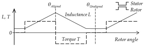
Figure 1.
Linearized phase inductance and reluctance torque at constant current I. The rotor and stator poles have the same width.
2.2. Torque Sharing Functions
The torque sharing function distributes the torque command value for each energized phase during the transition angle, where bought, incoming and outgoing phases can generate the torque. The purpose of the TSF is to prescribe such phase torque references in the transition region that the total motor torque has a small ripple. The shape of the TSF can follow a specific mathematical function or be derived by solving complex optimization problems [16].
This study used a conventional sinusoidal TSF, which is often mentioned in the literature and has a straightforward implementation [4,13,17,18,19]. The shape of the function is similar to the torque characteristics of the SRM. The sinusoidal TSF in Figure 2 is defined as follows [17]:
where TXref(θ) is the reference torque for phase X, X∈{A,B,C}, θ is the rotor angle, θon is the turn-on or start angle, θov is the overlap angle, θoff is the start angle of the next phase, θp is rotor period, Tc is torque command, fup(θ) is rising, and fdn(θ) the declining part of the TSF.
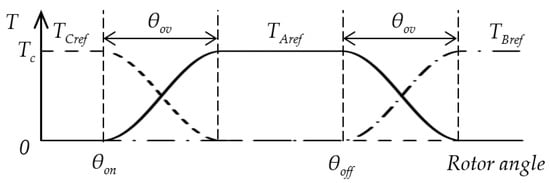
Figure 2.
Sinusoidal torque sharing functions for phases A, B, and C.
Functions fup(θ) and fdn(θ) depend on start and overlap angles θon and θov (θoff is the start angle of the next phase) and are determined by Equations (3) and (4).
The block diagram of the presented TSF-based control is shown in Figure 3. The TSF block translates the torque command Tc from the Speed Controller to three torque references TAref, TBref, and TCref for each motor phase using Equations (2)–(4).
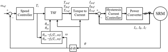
Figure 3.
Block diagram of the SRM control using TSF with optimized parameters θon and θov.
Optimal TSF parameters θon and θov depend on torque command Tc and actual rotor speed ω. They are calculated by functions f1(Tc,ω) and f2(Tc,ω), explained in Section 3. The torque reference is translated to the current reference in Torque to the Current block utilizing a T-θ-I look-up table. The Hysteresis Current Controller controls phase currents.
2.3. The Influence of Motor Geometry on TSF Control
The current control has some limitations. If the instantaneous current does not follow the current reference, there is a tracking error between the torque and the TSF. The simulation in Figure 4 shows the TSF torque reference translated to the current reference and the actual torque and current for 600 and 1500 rpm speeds. The current follows the reference at low speed, but we can see that a slow rise and drop in electric current to zero is critical, especially at high speed. The actual current is far from the reference. It flows after θAligned = 22.5° and creates torque in the opposite direction in Figure 4b, increasing torque ripple and producing unnecessary copper losses. The current drop cannot be accelerated at a given DC-link voltage due to the large value of the inductance in the aligned position. Therefore, the change in geometry can be used to reshape the motor torque profile to allow the current to decay without creating negative torque.
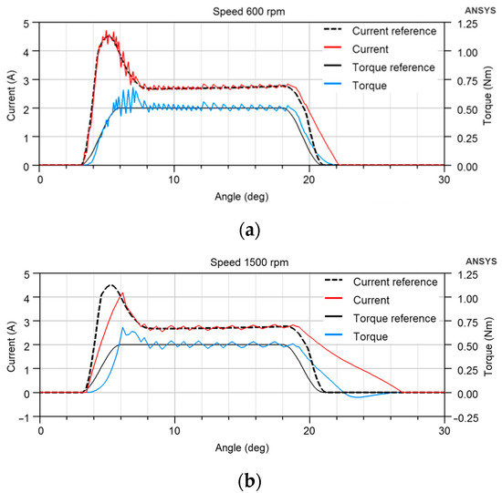
Figure 4.
Simulated TSF torque reference, current reference and actual torque and current for (a) 600 rpm, (b) 1500 rpm; θon = 3°, θov = 3°. The rotor and stator poles are equally wide, θAligned = 22.5°, and the load torque is 0.5 Nm.
Figure 5 illustrates the situation when the rotor pole is wider than the stator one. The linearized inductance profile has a flat top in an aligned position. Therefore, the torque is zero before changing the direction, giving time for the current to drop while retaining the average value of the torque pulse. This reduces the effect of tracking error on TSF control. The influence of the rotor pole width on the motor efficiency and torque ripple is described in Section 5.
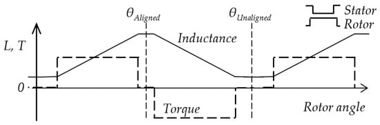
Figure 5.
Linearized phase inductance and reluctance torque at constant current I. The rotor pole is wider than the stator one.
3. Optimization of Torque Sharing Function Parameters
The TSF Equations (2)–(4) used in this research has two parameters: start angle θon and overlap angle θov. It can be expected that the optimal values of θon and θov are different for different motor speeds, torque, and geometry. Besides that, optimal values depend upon the selected objective function. Commonly used objective functions are torque ripple and copper loss. However, various motor applications may require other functions such as motor efficiency, overall converter-motor efficiency, noise, etc. In many cases, multi-objective optimization can be considered [15], or problem-specific criteria can be introduced, as in [19], where authors distinguish between motoring and generating quadrants to avoid negative torque generation.
Our research uses three objectives directly related to the desired properties of the drive performance. The fourth objective is a weighted criterion composed of the previous objectives:
- Relative torque ripple Trip:
- Torque ripple RMS TripRMS:where T is the instantaneous torque during the time interval (t1, t2).
- Motor efficiency η
- Weighted criterion Wcrit:where w1 and w2 are relative weights.
Two of these objectives, Motor efficiency and Torque ripple according to (6), are used to analyze the effect of rotor geometry on TSF control in Section 5.
The following section will describe the optimization procedure to calculate the values of functions f1(Tc,ω) and f2(Tc,ω) in discrete points for one rotor geometry. It should be noted that applying different objective functions leads to different functions f1 and f2.
The steps of the procedure are as follows:
- Building and verification of FEM model for given SRM;
- Determining the range and number of discrete values of load torque, speed, θon, and θov for a given geometry;
- Planning and execution of simulation experiments for each torque-speed combination;
- Executing a set of experiments for all combinations of θon and θov values, recording values of selected objective functions;
- Creating an interpolation function fint(θon,θov) for each objective function;
- Finding a minimum of fint and recording optimal values of θon and θov for actual torque-speed combinations for each objective function at given geometry.
- Interpolating θon = f1(Tc,ω) and θov = f2(Tc,ω) from optimal values recorded in the previous step.
The torque and speed range depends on where the motor is expected to operate. The choice of θon and θov range is related to the width of the region where the phase inductance is minimal (see Figure 1). FEM calculation speed and available time determine the number of discrete values in a range. A small number may not capture the local extreme, and a large number is time-consuming.
4. Rotor Pole Embrace
In this paper, the rotor pole width is expressed as the rotor pole embrace defined by the ratio of the pole arc to pole pitch (Figure 6). The change in the rotor pole embrace changes the look-up table in the Torque to the Current block in Figure 3. Therefore, new tables are calculated for several rotor geometries, and optimal functions f1 and f2 should be calculated for each geometry according to Section 3. The procedure for obtaining data to study the influence of the rotor geometry on TSF control is summarized in the following:
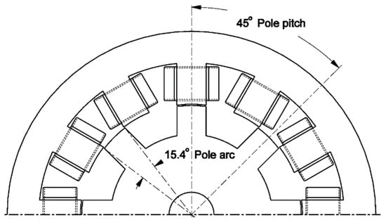
Figure 6.
The cross section of SRM with pole arc and pole pitch explanation.
- Creation of the FEM model for each pole embrace value.
- Calculation of the look-up tables for Torque to the Current block.
- Running TSF optimization for each geometry (Section 3).
- Analyzing results, finding optimal value of pole embrace and corresponding functions f1 and f2.
5. Results from Experiments and Simulation
5.1. FEM Model Verification
The rotor geometry influence on efficiency and torque ripple was studied on a 200 W three-phase 12/8 pole switched reluctance motor with a rated voltage of 120 V and maximum phase current 6 A (Table 1). The maximum static torque is 2.5 Nm. The motor is primarily designed for variable speed drives ranging from 300 to 1500 rpm. Figure 6 shows a motor cross section.

Table 1.
SRM specification.
Figure 7 shows the motor test bench and measurement devices. The three-phase asymmetric H-bridge power converter drives the SRM, and an induction motor is used as a controlled load. The torque was measured by Torque sensor KISTLER 4520A20 with CoMo torque evaluation instrument 4700BP0UA (Kistler GmbH, Wien, Austria). After setting the constant current, the motor shaft was fixed at angles from 0 to 360 degrees, and the torque value was recorded to get the static torque profile. The phase inductance was calculated from the voltage, current, power and phase shift values for the first harmonic frequency measured by the Infratek 106A Power Analyzer (Infratek AG, Uetikon am See, Switzerland) at several current values and positions of the rotor.
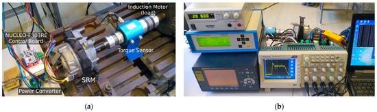
Figure 7.
Motor test bench (a) and measurement devices (b).
The FEM model of SRM was built in ANSYS Maxwell according to the mechanical dimensions of the motor. Static torque and phase inductance measurement was used for final model tuning. A comparison of measured and FEM inductance profiles of the studied motor is given in Figure 8. The model precision for aligned inductance at 22.5° and the current range up to 6 A is sufficient. Figure 9 shows the measured and simulated torque profile for phase currents 3 A and 6 A. It reveals a slight asymmetry in motor torque generation.
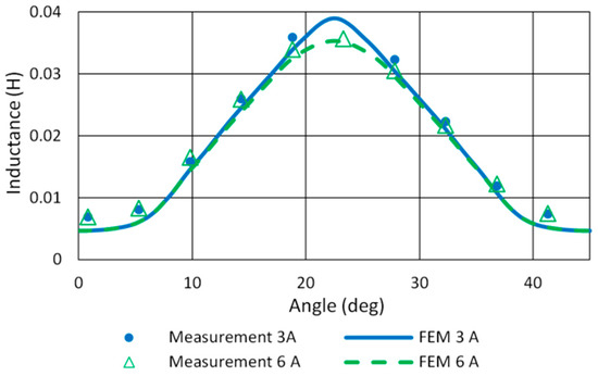
Figure 8.
Measured and FEM inductance profiles of 12/8 SRM.
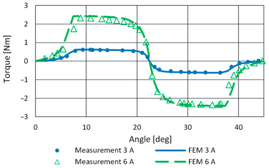
Figure 9.
Measured and FEM calculated torque profiles.
5.2. Optimization of TSF
To illustrate the optimization procedure, Figure 10 shows the results of procedure step 3.b (Section 3), which are functions fint(θon,θov) for three objectives obtained by a piecewise cubic interpolation of FEM calculations. The figure displays Motor efficiency η, Relative torque ripple Trip, and Torque ripple RMS TripRMS for one operating point: load torque 1 Nm and speed 600 rpm. We chose the start angle range from 0° to 5° and the overlap angle from 1° to 5° (step 1°) because the region between the minimum inductance and the rising part of the inductance profile in Figure 8 is approximately 5 degrees wide. Selected ranges cover the minimum of objectives Relative torque ripple and Torque ripple RMS, and the number of simulation runs to obtain data for one operating point was 30.
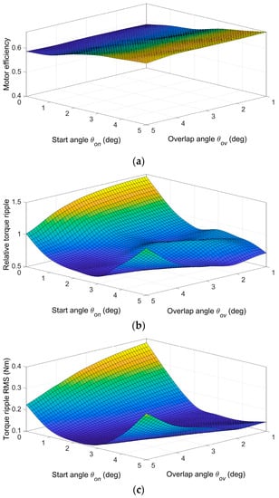
Figure 10.
Interpolated functions for (a) Motor efficiency, (b) Relative torque ripple, and (c) Torque ripple RMS for one operating point: load torque 1 Nm, speed 600 rpm.
The minimum of fint(θon,θov) in Figure 10 defines optimal values of θon and θov for a given operating point and given objective function. Different objective functions lead to different optimal values of θon and θov. Therefore, SRM application-dependent objective function, weighted criterion, or multi-objective (Pareto) optimization should be used. The choice depends on the requirements that must be met. From Figure 10, it is clear that the torque ripple reduction leads to a decrease in efficiency. For example, moving to a minimum Torque ripple RMS (Figure 10c) will reduce efficiency by 3.94% from the maximum calculated value of 0.668. A weighted criterion is commonly used to achieve a trade-off between objectives. The selection of the objective function leads to different functions f1 and f2 used for TSF control. Figure 11 shows partial functions f1 and f2 for one torque value Tc = 1 Nm. The figure illustrates how objective selection changes functions. The weights in weighted criterion (7) are w1 = −0.4 and w2 = 0.6. A higher absolute value of the weight for the objective function means that the resulting angles will be more shifted towards the optimal angles of the given objective. The sign of the number indicates the search for the maximum or minimum.
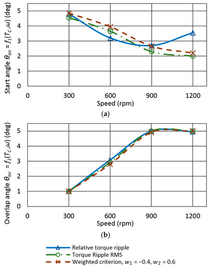
Figure 11.
Partial functions (a) f1(Tc,ω) and (b) f2(Tc,ω) for torque Tc = 1 Nm for calculation of optimal values of θon and θov, pole embrace 0.342.
The presented optimization procedure result is a set of points used to construct functions f1 and f2 for calculating optimal angle values in the motor control algorithm in Figure 3. For feasibility reasons, the set of values must be extended to define angles θon and θov at zero speed and zero torque. Figure 12 shows the final form of the functions f1(Tc,ω) and f2(Tc,ω), a cubic spline interpolation of optimal points, for the Torque ripple RMS objective. The control software uses look-up tables instead. It should be noted that the obtained functions are quasi-optimal because of the numerical nature of the presented procedure.
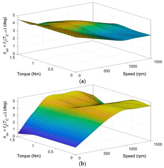
Figure 12.
Functions (a) f1(Tc,ω) and (b) f2(Tc,ω) for objective Torque ripple RMS, pole embrace 0.342.
Figure 13 shows the torque waveforms for several combinations of θon and θov. It illustrates that the torque waveforms for values near optimal (θon = 3°; θov = 3°) and (θon = 4°; θov = 3°) at a speed of 600 rpm for the objective Relative torque ripple and Weighted criterion, respectively, have smaller ripples than waveforms for non-optimal values.
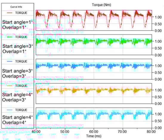
Figure 13.
Simulated motor torque for speed 600 rpm and load torque 1 Nm at different values of θon and θov.
5.3. Effect of Changing Rotor Embrace on TSF Control
Figure 14 shows the simulated TSF torque reference translated to the current reference and the actual torque and current for 600 and 1500 rpm speeds for the new rotor embrace of 0.42. The θon, θov, and the load torque are the same as in Figure 4 to document the effect of changing the rotor geometry on the TSF control. The current overshoot is eliminated at both low and high speeds because the motor already has a torque at the θon = 3°, and a higher current value is not needed to compensate for the small torque. The negative torque at a speed of 1500 rpm is shifted to a higher angle and has a smaller value, which decreased from −0.05 Nm in Figure 4b to −0.0468 Nm in Figure 14b.
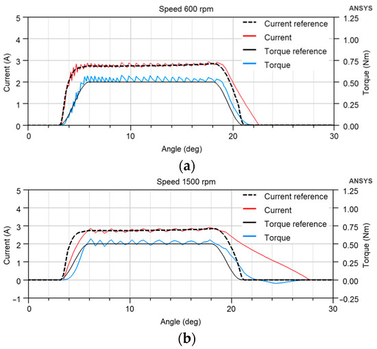
Figure 14.
Simulated TSF torque reference, current reference, and actual torque and current for (a) 600 rpm, (b) 1500 rpm at rotor pole embrace 0.42; θon = 3°, θov = 3°, θAligned = 22.5°, the load torque is 0.5 Nm.
5.4. Influence of Rotor Geometry on Efficiency and Torque Ripple
This section shows the results of simulation experiments that document the influence of rotor geometry on efficiency and torque ripple optimization objectives. Table 2 lists investigated values of the rotor pole embrace for each rotor geometry shown in Figure 15.
Table 2.
SRM rotor pole embrace values.
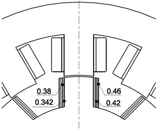
Figure 15.
The rotor pole geometry for pole embrace values from Table 2.
As mentioned in Section 3, for each operating point and geometry, it is necessary to evaluate the objective functions and find the optimal values for f1 and f2. Figure 16 shows the shapes of objective functions of Motor efficiency, and Figure 17 shows Torque ripple RMS TripRMS for two operating points for each rotor geometry. From Figure 16, it is possible to observe a shift of the maximum efficiency values to the area of lower start angles θon with the increase in speed. The start angle has a more significant effect on the efficiency than the overlap angle θov. Thus, if the only criterion is the efficiency, the θov could remain constant. However, in the case of the Torque ripple RMS TripRMS criterion, the minimum is already strongly dependent on both the start angle and the overlap angle (Figure 17). After quantifying the objective functions, we found the optimal values of f1 and f2 for each geometry. For optimization, we used the best values from fixed grid optimization parameters instead of interpolated objective functions described in Section 3.
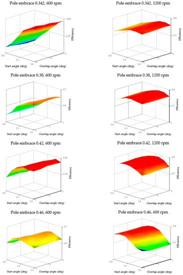
Figure 16.
Motor efficiency objective functions for speeds 600 and 1200 rpm for four rotor pole embrace values of 0.342, 0.38, 0.42, and 0.46; torque 1 Nm.
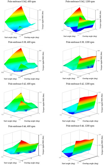
Figure 17.
Torque ripple RMS objective functions for speeds 600 and 1200 rpm for four rotor pole embrace values of 0.342, 0.38, 0.42, and 0.46; torque 1 Nm.
A comparison of the maximum efficiency for the efficiency-optimized TSF for each rotor pole embrace value is shown in Figure 18. The speed range is from 600 to 1500 rpm, and the load torque range is from 0.5 to 1.5 Nm. The figure shows the maximum efficiency at an embrace value of 0.42. Further increasing the pole width leads to a slight decrease in efficiency of −0.37% on average and a maximum of −0.67%. The existing motor with a pole embrace of 0.342 has the lowest efficiency in the entire investigated range. Changing the pole embrace significantly affects efficiency at higher speeds of 900 to 1500 rpm. The average efficiency increase is 2.15%, and the maximum is 2.64% at 900 rpm, 1.5 Nm.
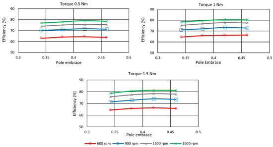
Figure 18.
Rotor pole embrace influence on the efficiency of SRM controlled by efficiency-optimized TSF.
The effect of the rotor pole embrace on Torque ripple RMS TripRMS is shown in Figure 19. The ripple value decreases with the increase in pole width. A more significant reduction is in the range from 900 to 1500 rpm. The pole embrace has a negligible effect on the ripples at 600 rpm (low speed) for all investigated loads. In the case of optimization to the minimum torque ripple, it is not possible to say unambiguously which value of the pole embrace is most suitable. The selection will depend on the operating point at which the motor is most frequently located. If the motor is operated at higher speeds, then the value of the pole embrace can be as high as 0.46, with little loss in efficiency.
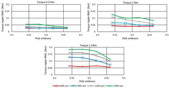
Figure 19.
Rotor pole embrace influence on Torque ripple RMS controlled by Torque ripple RMS optimized TSF.
6. Conclusions
A properly tuned SRM control method and modified geometry increase efficiency and reduce torque ripple. This article describes the procedure for finding the optimal parameters of sinusoidal TSF control applied to several rotor geometries to study the influence of rotor geometry on TSF performance.
An advantage of the described TSF optimization procedure is that it can use any objective function calculated from FEM. In addition, the procedure itself can be applied to other SRM control methods and inherits their advantages and disadvantages. The described procedure is demonstrated on a 200 W three-phase SRM with three objective functions, including motor efficiency, which is essential in the case of electric vehicle battery life extension.
The research showed that the existing motor with a pole embrace of 0.342 has the lowest efficiency in the entire investigated range. Changing the pole embrace significantly affects efficiency at higher speeds of 900 to 1500 rpm. If efficiency is the most important objective, it is possible to determine a suitable rotor pole embrace value of 0.42. For other criteria, the choice is not so clear-cut and requires consideration of the SRM operating modes. If the motor is operated at higher speeds, then the value of the pole embrace can be as high as 0.46, with little loss in efficiency.
From the research results, it follows that when designing the motor structure, it is necessary to consider the chosen control method and vice versa. The parameters of the chosen control method must be optimized for a specific geometry. The advantage of the described procedure is that it makes it possible to find the best geometry according to the chosen objective and simultaneously has a precisely tuned control method.
Author Contributions
Conceptualization, Ž.F. and P.B.; methodology, P.B.; software, Ž.F. and P.B.; validation, P.B.; investigation, Ž.F. and P.B.; data curation, P.B.; writing—original draft preparation, P.B.; writing—review and editing, Ž.F.; funding acquisition, Ž.F. All authors have read and agreed to the published version of the manuscript.
Funding
This work was supported by the Slovak Research and Development Agency under contract No. APVV-18-0436 and by the Scientific Grant Agency of the Ministry of Education, Science, Research and Sport of the Slovak Republic, VEGA 1/0363/23.
Data Availability Statement
Research data can be made available for non-profit use in research and education upon a formal request to the corresponding author.
Conflicts of Interest
The authors declare no conflict of interest.
References
- Miller, T.J.E. Optimal design of switched reluctance motors. IEEE Trans. Ind. Electron. 2002, 49, 15–27. [Google Scholar] [CrossRef]
- Tursini, M.; Villani, M.; Fabri, G.; Di Leonardo, L. A switched-reluctance motor for aerospace application: Design, analysis and results. Electr. Power Syst. Res. 2017, 142, 74–83. [Google Scholar] [CrossRef]
- Belhadi, M.; Krebs, G.; Marchand, C.; Hannoun, H.; Mininger, X. Geometrical optimization of SRM on operating mode for automotive application. Electr. Eng. 2018, 100, 303–310. [Google Scholar] [CrossRef]
- Gan, C.; Wu, J.; Sun, Q.; Kong, W.; Li, H.; Hu, Y. A Review on Machine Topologies and Control Techniques for Low-Noise Switched Reluctance Motors in Electric Vehicle Applications. IEEE Access 2018, 6, 31430–31443. [Google Scholar] [CrossRef]
- Rahman, K.M.; Fahimi, B.; Suresh, G.; Rajarathnam, A.V.; Ehsani, M. Advantages of switched reluctance motor applications to EV and HEV: Design and control issues. IEEE Trans. Ind. Appl. 2000, 36, 111–121. [Google Scholar] [CrossRef]
- Saxena, S.; Le Floch, C.; MacDonald, J.; Moura, S. Quantifying EV battery end-of-life through analysis of travel needs with vehicle powertrain models. J. Power Sources 2015, 282, 265–276. [Google Scholar] [CrossRef]
- 360 Market Updates: Global Switched Reluctance Motors Market Research Report 2020. 7 January 2020. Available online: https://www.360marketupdates.com/global-switched-reluctance-motors-market-14837961 (accessed on 31 May 2022).
- Hamouda, M.; Amin, A.R.A.; Gouda, E. A New Constructed Geometry of a Switched Reluctance Motor for Reduced Torque Ripple. Mansoura Eng. J. 2015, 40, 22–35. [Google Scholar] [CrossRef]
- Peniak, A.; Makarovic, J.; Rafajdus, P.; Vavrus, V.; Makys, P.; Buhr, K.; Fajtl, R. Design and optimization of switched reluctance motor for electrical vehicles. Electr. Eng. 2017, 99, 1393–1401. [Google Scholar] [CrossRef]
- Di Barbaa, P.; Mognaschia, M.E.; Przybylskib, M.; Rezaeia, N.; Slusarekb, B.; Wiak, S. Geometry optimization for a class of switched-reluctance motors: A bi-objective approach. Int. J. Appl. Electromagn. Mech. 2018, 56, 107–122. [Google Scholar] [CrossRef]
- Lee, J.; Seo, J.H.; Kikuchi, N. Topology optimization of switched reluctance motors for the desired torque profile. Struct. Multidiscip. Optim. 2010, 42, 783–796. [Google Scholar] [CrossRef]
- Byun, J.; Hahn, S. Topology Optimization of Switched Reluctance Motor Using Mutual Energy Method. Int. J. Appl. Electromagn. Mech. 2001, 13, 421–426. [Google Scholar] [CrossRef]
- Ye, W.; Ma, Q.S.; Zhang, P.M. Improvement of the Torque-Speed Performance and Drive Efficiency in an SRM Using an Optimal Torque Sharing Function. Appl. Sci. 2018, 8, 720. [Google Scholar] [CrossRef]
- Zhang, M.; Bahri, I.; Mininger, X.; Vlad, C.; Xie, H.Q.; Berthelot, E. A New Control Method for Vibration and Noise Suppression in Switched Reluctance Machines. Energies 2019, 12, 1554. [Google Scholar] [CrossRef]
- Li, H.; Bilgin, B.; Emadi, A. An Improved Torque Sharing Function for Torque Ripple Reduction in Switched Reluctance Machines. IEEE Trans. Power Electron. 2019, 34, 1635–1644. [Google Scholar] [CrossRef]
- Ye, J.; Bilgin, B.; Emadi, A. An Offline Torque Sharing Function for Torque Ripple Reduction in Switched Reluctance Motor Drives. IEEE Trans. Energy Convers. 2015, 30, 726–735. [Google Scholar] [CrossRef]
- Xue, X.D.; Cheng, K.W.E.; Ho, S.L. Optimization and Evaluation of Torque-Sharing Functions for Torque Ripple Minimization in Switched Reluctance Motor Drives. IEEE Trans. Power Electron. 2009, 24, 2076–2090. [Google Scholar] [CrossRef]
- Ro, H.-S.; Lee, K.-G.; Lee, J.-S.; Jeong, H.-G.; Lee, K.-B. Torque Ripple Minimization Scheme Using Torque Sharing Function Based Fuzzy Logic Control for a Switched Reluctance Motor. J. Electr. Eng. Technol. 2015, 10, 118–127. [Google Scholar] [CrossRef]
- Üstün, O.; Önder, M. An Improved Torque Sharing Function to Minimize Torque Ripple and Increase Average Torque for Switched Reluctance Motor Drives. Electr. Power Components Syst. 2020, 48, 667–681. [Google Scholar] [CrossRef]
- Xia, Z.; Bilgin, B.; Nalakath, S.; Emadi, A. A New Torque Sharing Function Method for Switched Reluctance Machines With Lower Current Tracking Error. IEEE Trans. Ind. Electron. 2021, 68, 10612–10622. [Google Scholar] [CrossRef]
- Ferková, Ž.; Bober, P. An off-line Optimization of Torque Sharing Functions for Switched Reluctance Motor Control. In Proceedings of the 2021 IEEE International Workshop of Electronics, Control, Measurement, Signals and their application to Mechatronics (ECMSM), Liberec, Czech Republic, 21–22 June 2021; pp. 1–4. [Google Scholar] [CrossRef]
- Abhijith, V.; Hossain, M.J.; Lei, G.; Sreelekha, P.A.; Monichan, T.P.; Rao, S.V. Hybrid Switched Reluctance Motors for Electric Vehicle Applications with High Torque Capability without Permanent Magnet. Energies 2022, 15, 7931. [Google Scholar] [CrossRef]


Disclaimer/Publisher’s Note: The statements, opinions and data contained in all publications are solely those of the individual author(s) and contributor(s) and not of MDPI and/or the editor(s). MDPI and/or the editor(s) disclaim responsibility for any injury to people or property resulting from any ideas, methods, instructions or products referred to in the content. |
© 2023 by the authors. Licensee MDPI, Basel, Switzerland. This article is an open access article distributed under the terms and conditions of the Creative Commons Attribution (CC BY) license (https://creativecommons.org/licenses/by/4.0/).