Article

Research on HMCVT Parameter Design Optimization Based on the Service Characteristics of Agricultural Machinery in the Whole Life Cycle

1
Department of Vehicle Engineering, Nanjing Forestry University, Nanjing 210037, China
2
College of Engineering, Nanjing Agricultural University, Nanjing 210031, China
*
Author to whom correspondence should be addressed.
Machines 2023, 11(6), 596; https://doi.org/10.3390/machines11060596
Submission received: 20 April 2023 / Revised: 18 May 2023 / Accepted: 25 May 2023 / Published: 1 June 2023
(This article belongs to the Special Issue Agricultural Machinery and Robotics: Design, Control and Applications)

Abstract

:
The HMCVT (Hydro-mechanical Continuously Variable Transmission) can realize continuously variable speed in a large range and transmit high power through power diving, and thus, it is widely applied in agricultural machineries, such as tractors. The engineering technology requirements of precision agriculture and intelligent agriculture have put forward higher requests for the research and development of HMCVT. In order to further improve the performance of HMCVT in the design stage and match the service characteristics of agricultural tractors in the whole life cycle, this paper proposes a new HMCVT optimization design method which mainly consists of 5 steps. The proposed method takes the regular and continuous transmission ratio variation, matching the working requirements in the whole life cycle of agricultural tractors and transmission efficiency maximization as comprehensive objectives. The improved genetic algorithm (I-GA) is applied. The HMCVT efficiency characteristic model combines the characteristic efficiency model of the hydraulic system, which has been verified, and the theoretical calculation model based on the engaging power method. By analyzing the statistical data of the tractor speed operating frequency in the whole life cycle, the proposed method is used to determine the weight of each hydro-mechanical power dividing stage (i.e., HM stage) service time. In the design process, the HMCVT efficiency is integrated with the displacement ratio so as to realize the evaluation of the maximum efficiency in the whole life cycle of the tractor. Research results show that the proposed method can improve HMCVT performance significantly, and the mean error between speed regulating characteristics and expected value in design is 1.04% or so. The HMCVT service efficiency in the whole life cycle of the tractor has been improved by 19.93%. The research in the paper offers a valuable reference for getting the law of HMCVT characteristics and performance improvement design of tractors.

1. Introduction

The tractor is one of the most important agricultural machinery [1,2] and faces complicated working conditions. Different operations, such as plowing, deep scarification, winter tillage, rotary tillage, seeding, transplanting, harvest, transportation, ditching and so on, require tractors to meet different operational requirements [3,4,5,6]. The performance of speed regulating transmission system of tractors, such as transmission ratio, the variation range of transmission ratio, transmission efficiency and so on, has a great influence on the fuel economy, dynamic property and other key performance indexes of the full tractor. The HMCVT (Hydro-Mechanical Continuously Variable Transmission) can realize continuously variable speeds in a large range and also inherits the advantages of mechanical transmission’s high efficiency and hydraulic transmission’s high power [7,8,9,10] while overcoming the disadvantages, and thus, can meet the requirements of agricultural machinery like tractors better. Therefore, the HMCVT is applied widely to agricultural and engineering machinery, such as tractors, and the research on HMCVT has great significance [11,12,13,14].
A reasonable design is the primary premise of the application of HMCVT transmission parameters to agricultural machinery like tractors. A good design for HMCVT transmission parameters of the tractor needs to take the following aspects into consideration: (1) the requirement of full tractor’s driving and working conditions on HMCVT speed variation range; (2) the continuity of transmission ratio variation intervals of variable speed stages of multi-stage HMCVT, to avoid any discontinuity point in the variation process of HMCVT transmission ratio from the minimum value to the maximum value, reduce the impact of stage shifting and improve the ride comfort of the tractor in operation and the reliability of parts; (3) the maximization of work efficiency of HMCVT for energy conservation and emission reduction.
Currently, there is relatively little research on transmission parameter optimization design based on HMCVT speed regulation characteristics and efficiency characteristics (that is, the transmission efficiency changes with the system operating conditions, efficiency can be calculated from the transmission output power and input power ratio). Ince and Guler [15] made detailed theoretical analysis and derivation of characteristic models for a new continuously variable speed system, including kinematic analysis, power flows and efficiencies at different stages. This study provides a valuable reference for the optimization design of a power-split infinitely variable power transmission system. Cheng and Lu [16] measured the speed regulation characteristics of the hydraulic system of HMCVT. Four models of speed regulation characteristics were established and compared. In this study, the improved particle swarm optimization algorithm and the modified HMCVT speed-regulating characteristic model are applied to the optimal design of transmission parameters. This is helpful in improving the practical application effect of the optimized design results. However, this study ignored the effect of the efficiency characteristics of HMCVT. Cheng et al. [17] used an improved genetic algorithm to optimize the transmission parameters of the HMCVT, which has a three-planetary alignment cooperative motion. This study takes into account the efficiency characteristics of HMCVT. However, the efficiency of the hydraulic system (mainly composed of pumps and motors) is assumed to be a constant value. Zhu et al. [18] designed a multi-stage HMCVT by taking the ratio of each gear’s maximum and minimum output speed as the fixed value (namely, equal-ratio design method). The approximate method was also adopted by He et al. [19] and Zhang et al. [20] (similar to the equal-ratio design method, the difference between each gear’s maximum and minimum output speed is taken as the fixed value in this study) and other studies. These methods have certain limitations in terms of design flexibility. Additionally, it is often difficult to take into account the efficiency characteristics of the system. This is not friendly in terms of energy conservation.
To sum up, the current research on HMCVT design has some shortcomings, including the following aspects: (1) The design only considers the speed regulation characteristics of HMCVT. This results in limited transmission efficiency during HMCVT operation. (2) The design method is not flexible. In the classical design method, the ratio of the maximum and minimum output speed of each gear is fixed by solving equations, or the difference between the maximum and minimum output speed of each gear is fixed. (3) The changing characteristics of hydraulic system efficiency are ignored. The hydraulic system efficiency is often set to a fixed value in the study. This leads to a certain error between the analysis results and the actual system. (4) The working characteristics of agricultural machinery in the whole life cycle affect the performance of HMCVT. Agricultural machinery often operates in certain speed ranges when traveling or operating. The design of HMCVT can further improve the working efficiency of the whole agricultural machinery by matching the service characteristics of agricultural machinery. No reports have been found on the introduction of full life cycle working characteristics of agricultural machinery in design. In addition, the heuristic intelligent optimization algorithm is used to optimize the HMCVT transmission parameters. The decision variables are many, as well as the objective functions are many and nonlinear. Therefore, it is difficult to optimize the design based on the characteristics of HMCVT transmission ratio change, the working characteristics of agricultural machinery in the whole life cycle, and the maximization of HMCVT transmission efficiency.
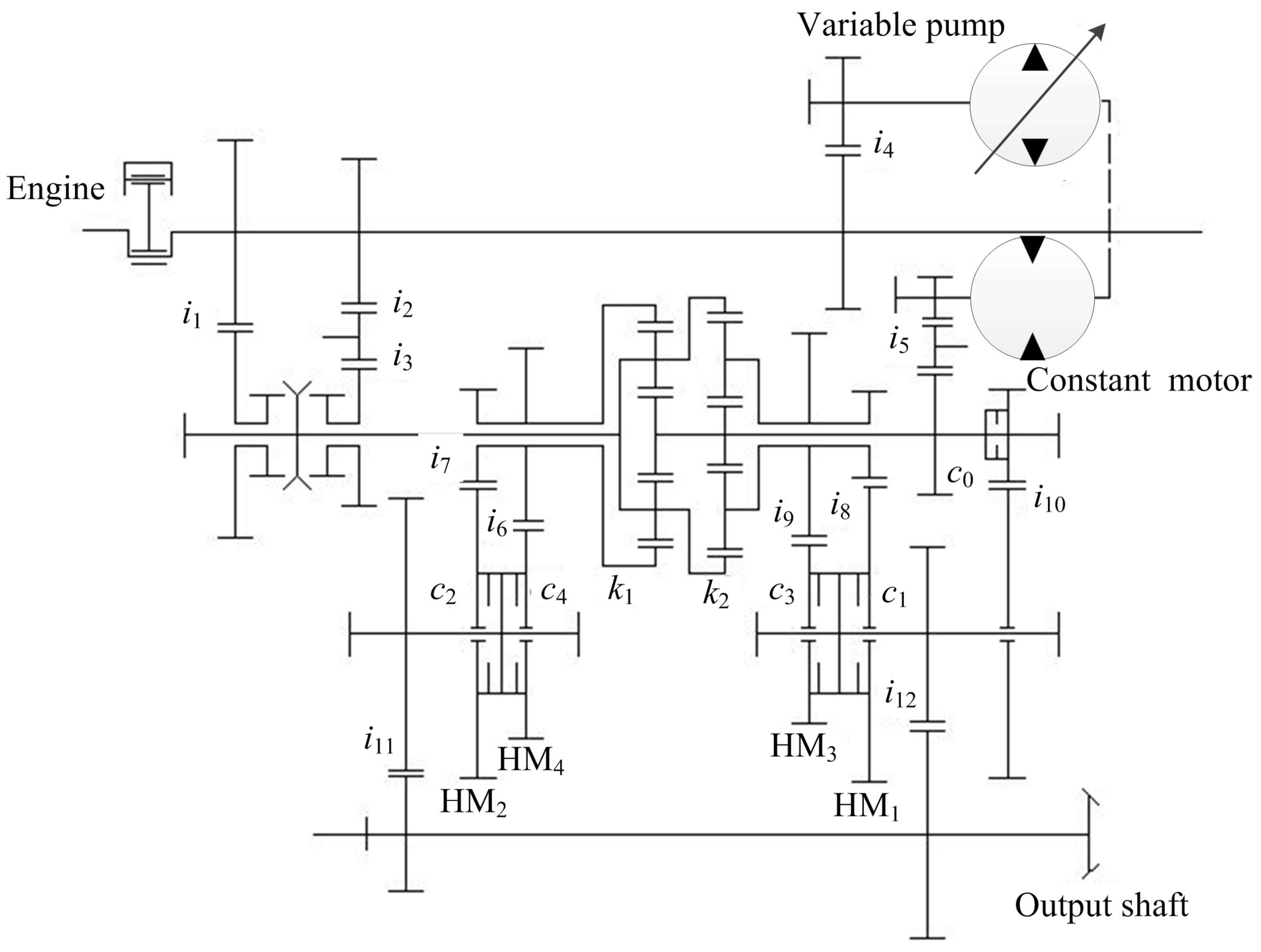
To solve the problems above, this paper proposes a transmission parameter optimization design method based on the verified speed regulation characteristic model and the verified hydraulic system efficiency characteristic model aiming at improving the performance (mainly referring to speed regulation characteristics and efficiency characteristics) of tractor HMCVT. The research in the paper considers a type of 5-stage tractor HMCVT as the object. According to the pump-motor efficiency model, the paper builds an HMCVT efficiency model by using the engaging power method. The paper uses the I-GA improved in four aspects (i.e., avoiding any super individual in the initial population, the adaptive scaling of population size in the iteration process, the adaptive changes of crossover probability and the adaptive changes of mutation probability) to optimize and improve HMCVT performance in speed regulating and efficiency characteristics. In the optimization, the paper considers the following three points as the comprehensive objective: the HMCVT speed regulating characteristics and efficiency characteristics matching the driving and working requirements of the tractor, the continuous speed regulating characteristic of HMCVT and the maximization of mean transmission efficiency of HMCVT. According to the HMCVT transmission parameter optimization design method for tractors proposed in the paper, the optimal matching design of HMCVT transmission parameters and performance improvement can be realized by obtaining the efficiency data samples of the “pump-motor” system selected in the HMCVT design and combining with the requirements of tractor operation and driving conditions.

2. The Transmission Principle and Characteristic Description of HMCVT for Agricultural Tractor

2.1. The Transmission Principle

Figure 1 shows the transmission principle of the 5-stage HMCVT of a tractor. The basic working principle of HMCVT is that the mechanical system’s power flow (the output power of the engine) and the hydraulic system’s power flow (the output power of variable-pump-constant-motor system) converge through a planetary row confluence structure for power confluence to realize the continuous variation of transmission ratio of HMCVT output end. The HMCVT is mainly composed of the variable-pump-constant-motor system, the Simpson double-row planetary gear train, 12 pairs of meshing gear systems (i1~i12) and 5 wet clutches (C0, C1, C2, C3 and C4). The HMCVT can realize one purely hydraulic system working stage (H0) and four hydro-mechanical power dividing working stages (stage HM1, stage HM2, stage HM3 and stage HM4) by means of the operations of different wet clutches. The HMCVT makes the tractor move backward and forward by shifting gear pair i1 and gear pairs i2 and i3. Because the purely hydraulic system working stage depends on the variable-pump-constant-motor system alone for power output, and the working stage only serves when the tractor starts up, the optimization design research in the paper doesn’t say much about the optimization design process of this stage.

2.2. The Speed Regulation Characteristics of the Total System

The speed regulation characteristics of the HMCVT are described in the previous study [21]. Its approximate power transmission route is as follows: stage HM2 and stage HM4 stages are the output of mechanical and hydraulic power after the confluence of the planetary row with characteristic parameter k1, and stage HM1 and stage HM3 stages are the output of mechanical and hydraulic power after the confluence of the planetary row with characteristic parameter is k2. The theoretical calculation models of the HMCVT each working stage transmission ratio are as follows:
i H M 1 = ( 1 + k 2 ) i 2 i 3 i 4 i 5 i 8 i 12 k 2 i 4 i 5 ε i 2 i 3
i H M 2 = k 1 i 2 i 3 i 4 i 5 i 7 i 11 ( 1 + k 1 ) i 4 i 5 + ε i 2 i 3
i H M 3 = ( 1 + k 2 ) i 2 i 3 i 4 i 5 i 9 i 12 k 2 i 4 i 5 ε i 2 i 3
i H M 4 = k 1 i 2 i 3 i 4 i 5 i 6 i 11 ( 1 + k 1 ) i 4 i 5 + ε i 2 i 3
in which i H M 1 , i H M 2 , i H M 3 and i H M 4 represent the transmission ratios of stage HM1, stage HM2, stage HM3 and stage HM4, respectively, and ε is the displacement ratio (the value ranges from −1 to 1).
According to reference [21], the average error of the theoretical calculation model and bench test is about 1.10%, and the maximum error is about 6.24%. The theoretical calculation model of the total system speed regulation characteristics is in good agreement with the actual value.

2.3. The Efficiency Characteristics of the Hydraulic System

The characteristic efficiency model of the hydraulic system is detailed in the previous study [21]. The established efficiency characteristic model of the hydraulic system is shown as follows:
η P = η P V η P M = 1 C s Δ P P ε μ n P 1 + C v μ n P ε Δ P P + C f ε
in which η P V is the volume efficiency of the variable pump; C s is the laminar leakage coefficient; ε is the displacement ratio of the variable pump; μ is the dynamic viscosity of hydraulic oil; n P is the pump speed; Δ P P is the pressure of pump system; η P M is the mechanical efficiency of the variable pump; C v is laminar resistance coefficient; C f is mechanical resistance coefficient.
η M = η M V η M M = 1 C v μ n M Δ P M C f 1 + C s Δ P M μ n M
in which η M V is the volume efficiency of the constant motor; n M is the motor speed; Δ P M is the pressure of constant motor system; η M M is the mechanical efficiency of the constant motor.
According to reference [21], the average error of the variable pump efficiency characteristic model is 3.84%, and that of the constant motor efficiency characteristic model is 1.37%. The calculation model of the efficiency characteristic of the hydraulic system has high precision.

3. Establishment of HMCVT Total Efficiency Characteristic Model

The HMCVT’s efficiency characteristics are composed of the mechanical system efficiency (i.e., the transmission efficiency of planetary gear mechanism and the transmission efficiency of fixed-axle gear train) and the transmission efficiency of the hydraulic system (i.e., the pump-motor system efficiency). This type of hydro-mechanical continuously variable transmission’s core confluence mechanism is the Simpson planetary gear mechanism, and there is only one planetary row that transmits power actually in the working mode of the hydraulic-mechanical stage, so we use the engaging power method [22,23] to analyze and calculate the working efficiency of hydraulic-mechanical power dividing stage of the 5-stage HMCVT. The engaging power method is a common method to calculate the efficiency of the gear mechanism. The basic principle is to assume that the friction loss power of the planetary gear system is constant (mainly depends on the force of each moving pair, friction coefficient between moving pair elements and relative motion speed) and does not consider the inertia force of rotating parts. In view of HMCVT, it is necessary to combine the existence of a power cycle in the transmission process. The specific derivation and analysis process is as follows.

3.1. Stage HM1 and Stage HM3

According to Figure 1 and the closed transmission principle, suppose the HMCVT’s input shaft is I, the output shaft is O, closed component a is planetary row P2’s gear ring, closed component b is planetary row P2’s sun gear, and component c is planetary row P2’s planet carrier. Chain a-I is the transmission chain connecting planetary row P2’s gear ring and input shaft I, passing through two pairs of gear pairs. Chain b-I is the transmission chain connecting planetary row P2’s sun gear and input shaft I, passing through three pairs of gear pairs and one variable-pump-constant-motor system.
According to the closed transmission calculation principle [24], calculate related transmission ratios and obtain i a I = 1 i 2 i 3 , i b I = ε i 4 i 5 , i c a b = k 2 1 + k 2 , i c b a = 1 1 + k 2 , i c I = i c I a + i c I b , i c I a = i c b a i b I , i c I b = i c a b i a I and i I c = 1 i c I .
To sum up:
i c I a i c I b = k 2 ( 1 + k 2 ) 2 i 2 i 3 i 4 i 5 ε
According to Equation (7), when displacement ratio ε 0 , i c I a i c I b 0 . In this working condition, the HMCVT’s work doesn’t have any phenomenon of the power cycle. In this case, the HMCVT’s efficiency calculation formula is as follows:
η HM 1 = η HM 3 = { 1 + | i I c | [ | i c I b i c I b i c I | ψ x + | i c I a | ( 1 η b I 1 ) + | i c I b | ( 1 η a I 1 ) ] } 1 η i g
in which η HM 1 and η HM 3 are the gross transmission efficiencies of stage HM1 and stage HM3 of 5-stage HMCVT when the displacement ratio ε 0 ; η i g is the gear engaging transmission efficiency between the output end of the planetary gear train and the output end of HMCVT; η a I = η i 2 η i 3 ; η b I = η P η M η i 4 η i 5 ; ψ x is the loss coefficient of engagement pair. The research in the paper sets the engaging transmission efficiency of a pair of gears to be 0.98.
According to Equation (7), when displacement ratio, i c I a i c I b < 0 . In this working condition, the HMCVT has a power cycle phenomenon, and the calculation formula of HMCVT efficiency is as follows:
η HM 1 = η HM 3 = { 1 + | i I c | [ | i c I b i c I b i c I | ψ x + | i c I a | ( 1 η b I ) + | i c I b | ( 1 η a I ) ] } 1 η i g
in which η HM 1 and η HM 3 are the gross efficiencies of stage HM1 and stage HM3 of 5-stage HMCVT when displacement ratio ε < 0 ; η a I = η i 2 η i 3 ; η b I = η P η M η i 4 η i 5 .

3.2. Stage HM2 and Stage HM4

With Figure 1, according to the closed transmission principle, suppose the HMCVT’s input shaft is I, the output shaft is O, closed component a is planetary row P1’s sun gear, closed component b is planetary row P1’s planet carrier and component c is planetary row P1’s gear ring. Chain a-I is the transmission chain connecting planetary row P1’s sun gear and input shaft I, passing through three pairs of gear pairs and one variable-pump-constant-motor system. Chain b-I is the transmission chain connecting planetary row P1’s planet carrier and input shaft I, passing through two gear pairs.
According to the closed transmission calculation principle [24], calculate related transmission ratios and obtain i a I = ε i 4 i 5 , i b I = 1 i 2 i 3 , i c a b = 1 k 1 , i c b a = 1 + k 1 k 1 , i c I = i c I a + i c I b , i c I a = i c b a i b I , i c I b = i c a b i a I , i I c = 1 i c I .
To sum up:
i c I a i c I b = ε ( 1 + k 1 ) k 1 2 i 2 i 3 i 4 i 5
According to Equation (10), when displacement ratio ε 0 , i c I a i c I b 0 . In this working condition, the HMCVT’s work doesn’t have any phenomenon of the power cycle. In this case, the HMCVT’s efficiency calculation formula is as follows:
η HM 2 = η HM 4 = { 1 + | i I c | [ | i c I i b I | ψ x + | i c I b | ( 1 η a I 1 ) + | i c I a | ( 1 η b I 1 ) ] } 1 η i g
in which η HM 2 and η HM 4 are the gross transmission efficiencies of stage HM2 and stage HM4 of 5-stage HMCVT when displacement ratio ε 0 ; η a I = η P η M η i 4 η i 5 ; η b I = η i 2 η i 3 .
According to Equation (10), when displacement ratio ε < 0 , i c I a i c I b < 0 . In this working condition, the HMCVT has a power cycle phenomenon, and the calculation formula of HMCVT efficiency is as follows:
η HM 2 = η HM 4 = { 1 + | i I c | [ | i c I i b I | ψ x + | i c I b | ( 1 η a I ) + | i c I a | ( 1 η b I ) ] } 1 η i g
in which η HM 2 and η HM 4 are the gross efficiencies of stage HM2 and stage HM4 of 5-stage HMCVT when displacement ratio ε < 0 ; η a I = η P η M η i 4 η i 5 ; η b I = η i 2 η i 3 .

4. The New HMCVT Optimization Design Method

The paper considers the HMCVT of the tractor as the design object. Suppose the maximum speed of a tractor running in the fields is 32 km/h, the radius of the wheel is 0.9 m, engine speed changes in the range of 750~2300 r/min, and the other train transmission ratio is 28. The calculation of tractor speed refers to the calculation formula of vehicle speed [25,26,27]. As the conceptual design phase for HMCVT is studied in this paper, tire slip is ignored. Then, i c v t _ min , the minimum transmission ratio of HMCVT to be designed, can be calculated and obtained, which is 0.87 (the minimum transmission ratio in stage HM4). Next, suppose the minimum steady speed in stage HM1 required by a tractor in field operations is 2 km/h (stage H0, i.e., the hydraulic transmission system, offers the speed for the tractor to start up and the speed less than 2 km/h). Additionally, to meet the tractor’s field driving requirement to large torque, the engine’s working speed is about 1500 r/min. Therefore, we can calculate and obtain that i HM 1 _ max , the maximum transmission ratio of stage HM1 of HMCVT, is 9.09.
Different working conditions have different requirements for the tractor’s speed. For instance, some rotary tillage and seeding tasks of the tractor are low-speed operations, while plowing, intertillage, and field transportation are medium-high-speed operations. The conventional transmission ratio design of the speed control system of tractors only considers the requirements of the full-vehicle dynamic property. However, the conventional HMCVT design generally adopts equal-difference or equal-ratio changing transmission design schemes for the convenience of design calculation. Therefore, the conventional design principle neglects not only the main working speed intervals in the life cycle of the tractor but also the influence of the transmission system’s efficiency characteristics on the full-vehicle energy saving of the tractor.
The paper proposes an optimization design method of transmission parameters considering the HMCVT efficiency maximization in the life cycle of the tractor. The steps are as follows:
Step 1. Analyze the statistical data of operating frequency of speed in the whole life cycle of the tractor.
Our design takes scholar Wang’s analysis of the research results of Resch and Renius for reference [28]. In the whole life cycle, the tractor spends 61~68% of working time in the speed interval of 4~12 km/h and 15~25% of working time in the speed interval of 12~20 km/h. Therefore, the paper designs the percentage of time of each time interval of the tractor in the whole life cycle as follows:
P t i m e _ m = { 61 + 68 2 = 64.5 % , 4 u a 12   km / h   ,   m = 1 15 + 25 2 = 20.0 % , 12 < u a 20   km / h ,   m = 2 100 84.5 = 15.5 % , Other   conditions ,   m = 3
Step 2. Calculate the variation range of transmission ratio corresponding to the high-frequency used speed interval of the tractor.
With the minimum working speed n e _ min and the maximum working speed n e _ max of the engine, calculate the minimum transmission ratios and the maximum transmission ratios of HMCVT corresponding to different speed intervals in calculation Equation (13). Suppose the minimum transmission ratio and the maximum transmission ratio of HMCVT are i _ min 1 and i _ max 1 , respectively, when 4 u a 12   km / h . Suppose the minimum transmission ratio and the maximum transmission ratio of HMCVT are i _ min 2 and i _ max 2 , respectively, when 12 < u a 20   km / h .
Step 3. Calculate the weight of service time of each hydro-mechanical power dividing stage (i.e., HM stage) of HMCVT.
According to the design results of a group of transmission parameters, calculate the proportion of the transmission ratio of each HM stage of HMCVT to the transmission ratio interval in Step 2 in the current design results. Next, according to the proportion and combined with the proportion ratio of each section’s service time in Step 1, estimate the proportion of service time of each HM stage in the whole life cycle of the tractor. Then, consider the proportion as the service time weight a η required by the optimization of the objective function in the subsequent optimization design of HMCVT.
a η k = P t i m e _ 1 L k _ 1 i max 1 i min 1 + P t i m e _ 2 L k _ 2 i max 2 i min 2 + P t i m e _ 3 L k _ 3 L k _ 0
in which a η k is the service time weight of the kth HM stage; L k _ 1 is the proportion of transmission ratio of the kth HM stage in interval [ i _ min 1 ,   i _ max 1 ] ; L k _ 2 is the proportion of transmission ratio of the kth HM stage in interval [ i _ min 2 ,   i _ max 2 ] ; L k _ 3 is the proportion of transmission ratio of the kth HM stage in other transmission ratio intervals; L k _ 0 is the rest of transmission ratio range of all HM stages in the intervals except [ i _ min 1 ,   i _ max 1 ] and [ i _ min 2 ,   i _ max 2 ] .
Step 4. Set objective function f i t n e s s ( X ) with the comprehensive optimization objective of transmission ratio continuity, transmission ratio variation range matching required speed of tractor and service efficiency maximization in the whole life cycle of the tractor.
min f i t n e s s ( X ) = a 1 f 1 ( X ) + a 2 f 2 ( X )
in which X is the variable to be optimized and X = [ i 2 i 3 , i 4 , i 5 , i 6 , i 7 , i 8 , i 9 , i 11 , i 12 , k 1 , k 2 ] (in which i 2 i 3 act as a whole to transmit power in the whole HMCVT transmission system, so they are combined with being one variable to be optimized in the optimization design; i 1 is a reverse gear and the HMCVT has a consistent working principle for moving forward and backward, so the paper sets i 1 = i 2 i 3 in the optimization design; i 10 is the transmission ratio value required by the purely hydraulic system stage in the case of starting up, and because the purely hydraulic system transmission ratio can realize continuously variable regulation by itself, the determination of i 10 ’s value only needs to match the maximum transmission ratio of stage HM1, so the optimization design in the paper doesn’t take the parameter into account.); a 1 and a 2 are the weight coefficients of the objective function; f 1 ( X ) is the objective function realizing the continuity of transmission ratio and the variation range of transmission ratio matching the required vehicle speed of the tractor, as shown in Equation (16); f 2 ( X ) is the objective function realizing the service efficiency maximization of the tractor in the whole life cycle, as shown in Equation (17).
f 1 ( X ) = | i HM 1 ( ε = 1 ) i HM 2 ( ε = 1 ) | + | i HM 1 ( ε = 1 ) 9.09 | + | i HM 2 ( ε = 1 ) i HM 3 ( ε = 1 ) | + | i HM 3 ( ε = 1 ) i HM 4 ( ε = 1 ) | + | i HM 4 ( ε = 1 ) i d |
in which ε is the displacement ratio of the variable pump; i d is the minimum transmission ratio of stage HM4 set in the optimization design of HMCVT. According to the design requirement, i d should take a value of 0.87. However, to ensure that HMCVT’s speed regulating characteristics meet the maximum vehicle speed requirement after optimization design, and also for the expectation of getting a vehicle speed as high as possible, the optimization design stage in the paper takes the value of i d less than 0.87.
The paper adopts the mean value of transmission efficiencies in working conditions of different engine speeds and different motor output end loads as the transmission efficiency of a fixed displacement ratio and writes it as η HM k ¯ ( ε ) the mean transmission efficiency in the displacement ratio. The research in the paper calculates the ratio of η HM k ¯ ( ε ) ’s integral value of variation interval of displacement ratio to the variation length of displacement ratio and considers it as the man value of transmission efficiency of each HM stage. Additionally, the research considers the sum value of the mean value of transmission efficiencies of stages and considers the sum value of the mean efficiency of HM stages and the product of efficiency weight as the service efficiency of HMCVT with currently designed parameters. Besides, the optimization process adopted in the paper is a process searching the minimum value of the objective function, so the paper considers the loss value of the system deducting service efficiency as the objective function of f 2 ( X ) .
f 2 ( X ) = 1 k = 1 4 a η k ε = 1 ε = 1 η HM k ¯ ( ε ) d ε 2
in which η HM k ¯ ( ε ) is the mean value of efficiency of the kth HM stage with displacement ratio of ε (Section 2 and Section 3 give the efficiency models of HM stages of the HMCVT); Constant 2 presents the variable length of displacement ratio of each HM stage.
The purpose of using the objective function f i t n e s s ( X ) ’s weight coefficients a 1 and a 2 is to balance the orders of magnitude of f 1 ( X ) and f 2 ( X ) , and, on the other hand, reflect the degree of importance tendency between f 1 ( X ) and f 2 ( X ) in the optimization design. In the optimization design of the paper, it’s recommended to substitute the original design parameters (Table 1) into Equations (16) and (17) to obtain the values of f 1 ( X 0 ) and f 2 ( X 0 ) through calculation and make a 1 = 1 f 1 ( X 0 ) and a 2 = 1 f 2 ( X 0 ) .
Step 5. Use a heuristic intelligent optimization algorithm for the optimization design of transmission parameters.
The heuristic optimization algorithm is widely used to solve problems in complex engineering projects [29,30,31,32,33,34], which can effectively solve nonlinear, multi-objective or multi-decision variable optimization problems. The case of optimization design in the paper has many variables to be optimized (a total of 11 variables to be optimized), and the calculation model of the objective function is complicated (i.e., it’s required to calculate the speed regulating characteristics in different working conditions of HMCVT for each individual in each iteration process of algorithm and consider the service time weight and efficiency of each HM stage in the whole life cycle of the tractor), so the research in the paper adopts the I-GA for the optimization design of transmission parameters. The GA has improved in the following four aspects: the super individual screening, the population size adaptive change, the adaptive changes of crossover probability and mutation probability. See reference [17] for the specific improvement process and optimization results after improvements.

5. Results and Discussion

In the optimization design, the paper sets the I-GA’s initial population size to be 500, and, in the process of iteration, the maximum value of adaptive change of population size to be 1000 and the maximum number of iterations to be 100. 
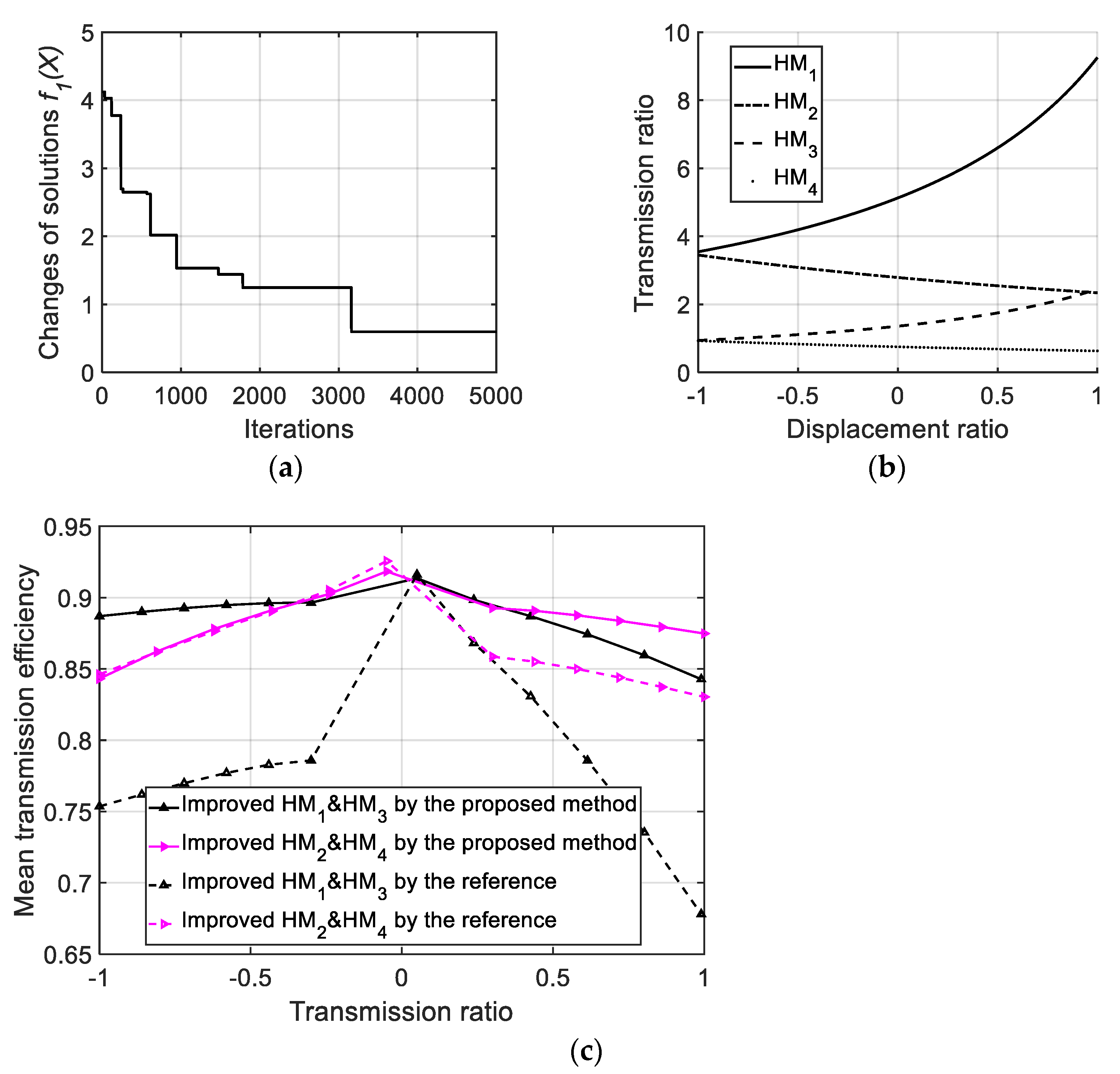
Figure 2 shows the iteration evolution curve.
According to Figure 2, the HMCVT’s optimization process has a fast rate of descent in the initial period (in the first 20 iterations, the objective function decreases from 4.5593 to 1.1491, decreasing by about 74.80%), indicating the I-GA can avoid the phenomenon of prematurity well in the early period of optimization. Meanwhile, because of the introduction of population size adaptive change and crossover & mutation probability adaptive change, the optimization process still has an evolution ability in the middle and later periods to get out of the optimal local solution.
Table 1 shows the optimization design results of HMCVT transmission parameters.
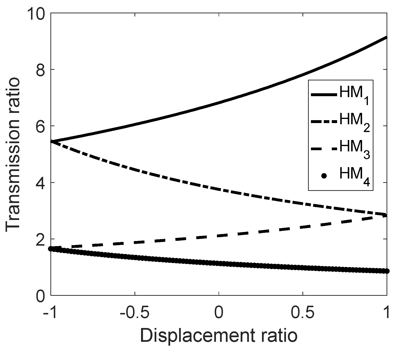
Figure 3 shows the transmission characteristics of HMCVT after the optimization design.
According to Figure 3, i HM 1 ( ε = 1 ) = 9.15 after optimization has an error of about 0.62% with the expected value in design; i HM 1 ( ε = 1 ) and i HM 2 ( ε = 1 ) have an error of about 0.62%; i HM 2 ( ε = 1 ) and have an error of about 0.98%; i HM 3 ( ε = 1 ) and i HM 4 ( ε = 1 ) have an error of about 1.94%; i HM 4 ( ε = 1 ) = 0.86 , less than 0.87 the expected value in design (indicating the maximum vehicle speed meets design requirement).
After optimization, the transmission ratio characteristics of each HMCVT working stage (a total of 4 HM stages) change continuously with the variable pump displacement ratio, without discontinuity point or transmission ratio mutation phenomenon. The total transmission ratio of the transmission system can be continuously changed from 9.15 to 0.86, meeting the design requirements of the tractor in Section 4 (the maximum speed required for the tractor to drive in the fields is 32 km/h, and the minimum steady speed of stage HM1 is 2 km/h). Specifically, the transmission ratio varies from 5.44 to 9.15 (stage HM1), 2.86 to 5.47 (stage HM2), 2.83 to 1.68 (stage HM3), and 1.65 to 0.86 (stage HM4) for each HMCVT working stage. The transmission ratio of HMCVT presents a nonlinear change characteristic, which corresponds to Equations (1)–(4), and the degree of nonlinearity decreases with the increase of the HM stage.
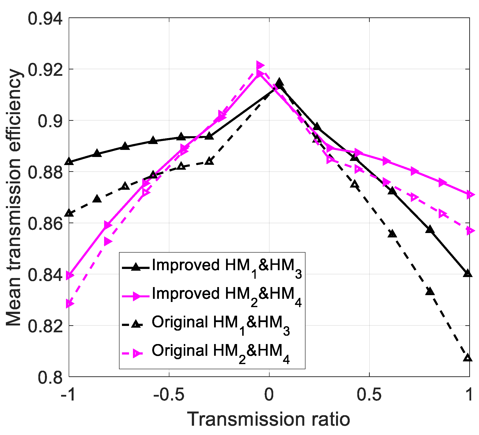
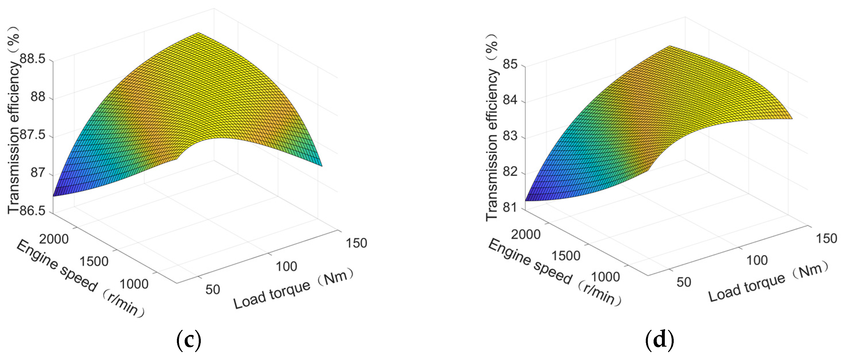
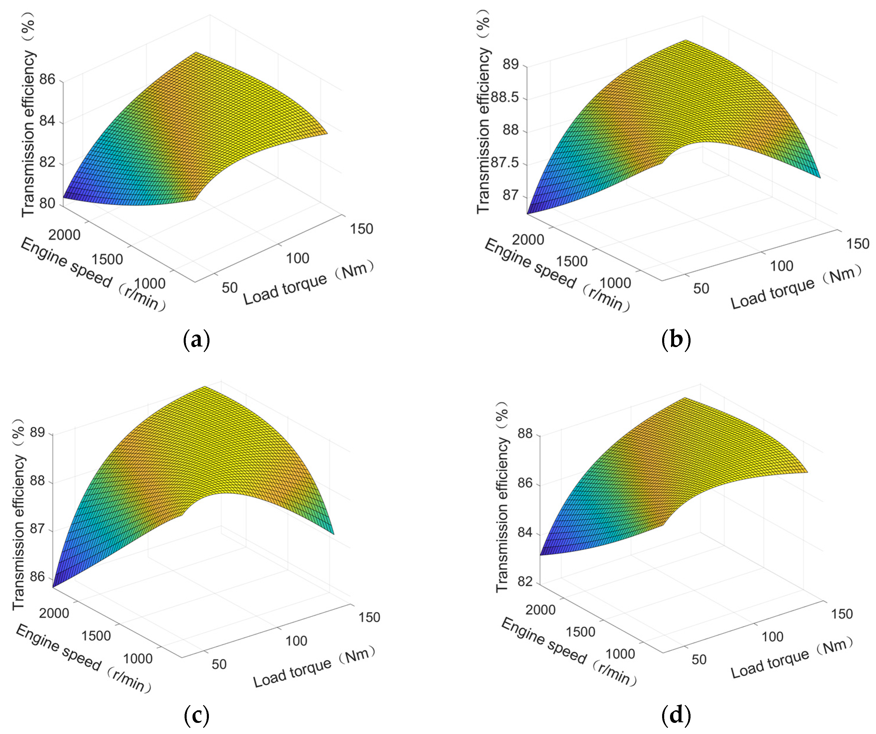
Figure 4 shows the comparison of mean transmission efficiencies of HM stages of HMCVT (i.e., the mean value of efficiencies with different engine speeds and different motor output end loads in each displacement ratio condition. The calculation in the paper sets the engine speed to be 750~2300 r/min and the motor output end load to be 34.71~138.84 Nm. Meanwhile, the paper chooses 50 evenly spaced working conditions in the engine speed interval and the output end load interval. Therefore, we calculate the mean of transmission efficiencies in a total of 2500 working conditions in the case of one displacement ratio) before and after the optimization.
According to Figure 4, after the optimization, the mean transmission efficiencies of HM stages of HMCVT in the displacement ratio working conditions (i.e., calculating the mean value of transmission efficiencies in a total of 2500 working conditions with a certain displacement ratio) all improve to a certain extent. For stage HM1 and stage HM3, the mean transmission efficiency is improved by 4.08% to the most and 1.72% on average. For stage HM2 and stage HM4, the mean transmission efficiency is improved by 1.64% to the most and 0.71% on average. As for the improvement result considering HMCVT service efficiency in the whole life cycle of the tractor (i.e., objective function f 2 ( X ) ), the value after optimization is improved by 19.93% compared with the value before optimization.
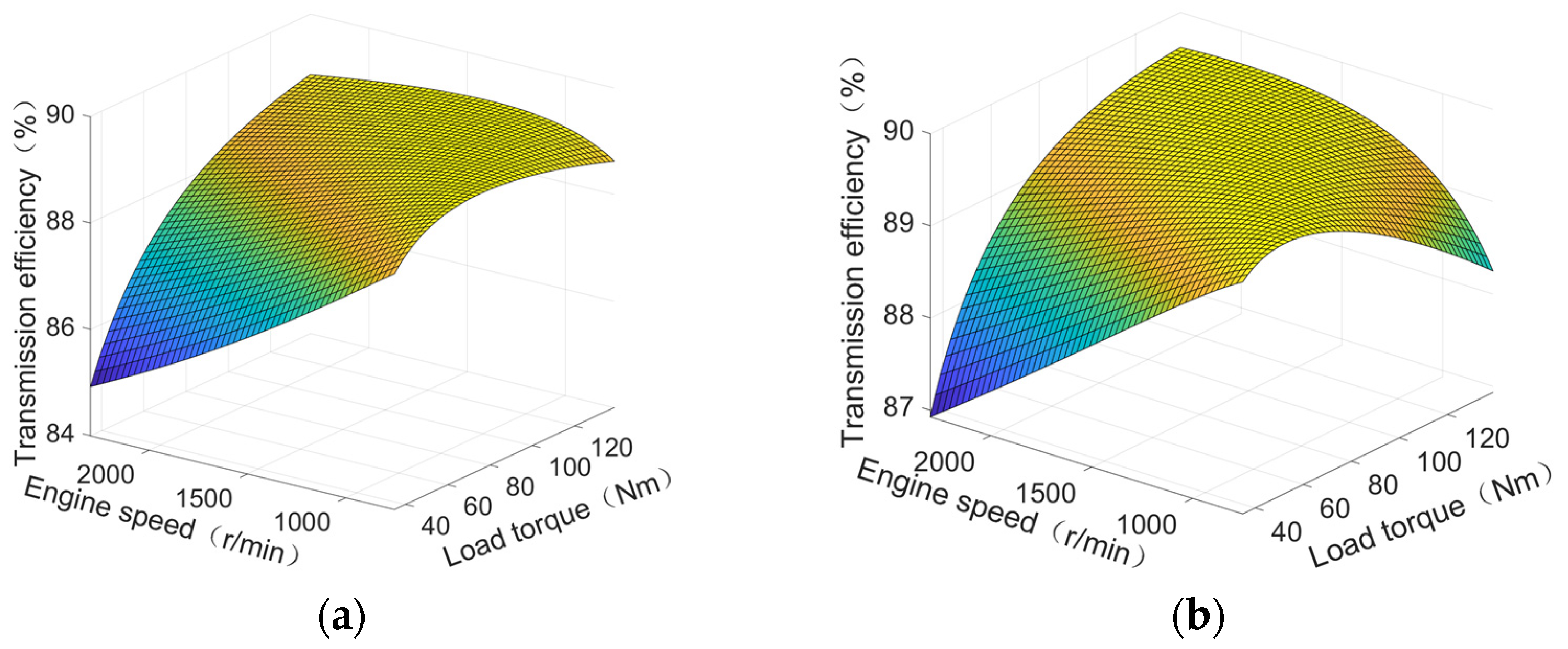
Figure 5 (corresponding to stage HM1 and stage HM3) and Figure 6 (corresponding to stage HM2 and stage HM4) show the gross transmission efficiencies of the system of HMCVT in different working conditions (for example, in the case that engine speed is 750~2300 r/min, motor output end load is 34.71~138.84 Nm, and the displacement ratio is in −1~1)
In order to further demonstrate the effectiveness of the proposed design method, it is compared with the traditional design method (i.e., the design method that ignores the efficiency characteristics of HMCVT). Taking reference [16] as an example, the traditional design method adopts the improved particle swarm optimization algorithm to optimize the design of HMCVT. The design results are shown in Figure 7.
According to Figure 7, the design results of the traditional design method can well meet the requirements of HMCVT speed regulation characteristics. However, the HMCVT efficiency characteristics are ignored in the design process, which leads to relatively poor efficiency characteristics after optimization design and high energy consumption of the system. For stage HM1 and stage HM3, the mean transmission efficiency is reduced by 24.30% to the most and 13.05% on average. For stage HM2 and stage HM4, the mean transmission efficiency is reduced by 5.35% to the most and 2.21% on average. Considering the whole life cycle of the tractor, the design result of HMCVT service efficiency decreases by 20.42%.

6. Conclusions

The paper proposes an HMCVT transmission parameter optimization design method combining the speed regulating characteristic model, the engaging power method, the pump-motor system efficiency model, and the service efficiency estimation method of the speed control system in the whole life cycle of the tractor. Besides, the paper proposes an objective function f i t n e s s ( X ) with the comprehensive optimization design objective of the continuous variation range of transmission ratios of HM stages of HMCVT, transmission variation range matching required speed of tractor and service efficiency maximization in the whole life cycle of the tractor. The research in the paper adopts the I-GA (of which the improvements include the super individual screening, the population size adaptability, and the crossover and mutation probability adaptability) for the optimization design of a 5-stage HMCVT. Results show that the I-GA has great optimization results. The mean value of error between speed regulating characteristics and expected value in design is about 1.04%. HMCVT’s service efficiency in the whole life cycle of the tractor has been improved by 19.93%. The method, on the one hand, offers technical means for the building of efficiency models in multiple working conditions of HMCVT (i.e., the engine working speed, the output end load and the displacement ratio of HMCVT), and on the other hand, offers guidance for the design of variable speed transmission system considering the service characteristics in the whole life cycle of the vehicle.

Author Contributions

Methodology, Z.C.; software, Z.C.; validation, Z.C.; investigation, Z.C.; resources, Z.L.; writing—original draft preparation, Z.C.; writing—review and editing, Z.C. and Z.L.; supervision, Z.L.; and project administration, Z.C. All authors have read and agreed to the published version of the manuscript.

Funding

This research was funded by the National Natural Science Foundation of China (grant number: 52105063).

Data Availability Statement

The data presented in this study are available on demand from the corresponding author or first author at [email protected].

Acknowledgments

The authors thank the National Natural Science Foundation of China for funding. We also thank the anonymous reviewers for providing critical comments and suggestions that improved the manuscript.

Conflicts of Interest

The authors declare no conflict of interest.

References

  1. Xie, B.; Wu, Z.B.; Mao, E.R. Development and prospect of key technologies on agricultural tractor. Trans. Chin. Soc. Agric. Mach. 2018, 49, 1–17. [Google Scholar]
  2. Liu, Z.J.; Zhang, G.Q.; Chu, G.P.; Niu, H.L.; Zhang, Y.Z.; Yang, F.Z. Design matching and dynamic performance test for an HST-based drive system of a hillside crawler tractor. Agriculture 2021, 11, 466. [Google Scholar] [CrossRef]
  3. Qian, Y.; Cheng, Z.; Lu, Z.X. Study on stepwise optimization of shift quality of heavy-duty tractor HMCVT based on five factors. J. Nanjing Agric. Univ. 2020, 43, 564–573. [Google Scholar]
  4. Fang, S.S.; Lu, Z.X.; Wang, Z.C.; Diao, X.Y.; Lu, Y.; Gong, J.H.; Zhu, C.Y. Design and prototype performance experiments of steering-by-wire hydraulic pressure system of tractor. Trans. Chin. Soc. Agric. Eng. 2017, 33, 86–93. [Google Scholar]
  5. Sun, J.B.; Chu, G.P.; Pan, G.T.; Meng, C.; Liu, Z.J.; Yang, F.Z. Design and performance test of remote control omnidirectional leveling hillside crawler tractor. Trans. Chin. Soc. Agric. Mach. 2021, 52, 358–369. [Google Scholar]
  6. Liu, M.N.; Zhou, Z.L.; Xu, L.Y.; Zhao, J.H.; Yan, X.H. Multi-objective optimization and design of tractor trailer systems. Trans. Chin. Soc. Agric. Eng. 2017, 33, 62–68. [Google Scholar]
  7. Xia, Y.; Sun, D.Y. Characteristic analysis on a new hydro-mechanical continuously variable transmission system. Mech. Mach. Theory 2018, 126, 457–467. [Google Scholar] [CrossRef]
  8. Cheng, Z.; Zheng, S.Q.; Qian, Y.; Lu, Z.X.; Zhang, H.J. Based on improved SA and GA a new method for optimizing transmission parameters of automotive HMCVT. J. Mech. Strength 2020, 42, 61–66. [Google Scholar]
  9. Rossetti, A.; Macor, A. Multi-objective optimization of hydro-mechanical power split transmissions. Mech. Mach. Theory 2013, 62, 112–128. [Google Scholar] [CrossRef]
  10. Zhang, G.Q.; Zhang, H.T.; Ge, Y.Y.; Qiu, W.; Xiao, M.H.; Xu, X.M.; Zhou, M.H. Mechanical efficiency of HMCVT under steady-state conditions. Shock Vib. 2021, 2021, 4275922. [Google Scholar] [CrossRef]
  11. Cheng, Z.; Lu, Z.X. System response modeling of HMCVT for tractors and the comparative research on system identification methods. Comput. Electron. Agric. 2022, 202, 107386. [Google Scholar] [CrossRef]
  12. Chen, Y.; Qian, Y.; Lu, Z.X.; Zhou, S.; Xiao, M.H.; Bartos, P.; Xiong, Y.P.; Jin, G.H.; Zhang, W. Dynamic characteristic analysis and clutch engagement test of HMCVT in the high-power tractor. Complexity 2021, 2021, 8891127. [Google Scholar] [CrossRef]
  13. Yu, J.; Chen, H.; Liu, J.H. Speed ratio follow-up control of HMCVT based on variable universe fuzzy PID. China Mech. Eng. 2019, 30, 1226–1232. [Google Scholar]
  14. Zhang, M.Z.; Wang, Q.S.; Bai, D.Y.; Yin, Y.X.; Hao, X.Y. Speed changing law of hydro-mechanical CVT based on maximum efficiency of tractors. Trans. Chin. Soc. Agric. Eng. 2016, 32, 74–78. [Google Scholar]
  15. Ince, E.; Guler, M.A. Design and analysis of a novel power-split infinitely variable power transmission system. J. Mech. Des. 2019, 141, 054501. [Google Scholar] [CrossRef]
  16. Cheng, Z.; Lu, Z.X. Regression-Based Correction and I-PSO-Based Optimization of HMCVT’s Speed Regulating Characteristics for Agricultural Machinery. Agriculture 2022, 12, 580. [Google Scholar] [CrossRef]
  17. Cheng, Z.; Lu, Z.X.; Qian, J. A new non-geometric transmission parameter optimization design method for HMCVT based on improved GA and maximum transmission efficiency. Comput. Electron. Agric. 2019, 167, 105034. [Google Scholar] [CrossRef]
  18. Zhu, Z.; Gao, X.; Zhu, Y. Reverse Design of a Hydro-mechanical Continuously Variable Transmission. Mech. Sci. Technol. Aerosp. Eng. 2016, 35, 545–550. [Google Scholar]
  19. He, C.K.; Lang, P.F.; Kang, M.; Zhang, H.J. Transmission design and force analysis of HMCVT for high power tractor. J. Mech. Transm. 2018, 42, 54–59. [Google Scholar]
  20. Zhang, P.C.; Ni, X.D.; Mei, W.J.; Peng, X.R. Design and characteristic analysis of hydro-mechanical continuous variable transmission of cotton picker. Mach. Des. Manuf. 2017, 10, 64–66. [Google Scholar]
  21. Cheng, Z. Research on System Dynamics Analysis and Continuously Variable Speed of Tractor. Ph.D. Thesis, Nanjing Agricultural University, Nanjing, China, 2020. [Google Scholar]
  22. Li, J.L.; Liu, L.T.; Xiao, M.H.; Wang, T.T.; Wang, X.; Zhang, H.J. Research on dynamic characteristics of hydro-mechanical continuously variable transmission. J. Mech. Strength 2017, 39, 14–19. [Google Scholar]
  23. Wang, C. Study of efficiency calculation of planetary gear trains based on meshing power method. Manuf. Technol. Mach. Tool 2016, 80–82. [Google Scholar] [CrossRef]
  24. Zhang, M.Z. Control Strategy Development for Multi-Range Hydro-Mechanical Continuously Variable Transmission in Tractors. Ph.D. Thesis, Xi’an University of Technology, Xi’an, China, 2007. [Google Scholar]
  25. Li, D.X.; Xu, B.; Tian, J.; Ma, Z.S. Energy management strategy for fuel cell and battery hybrid vehicle based on fuzzy logic. Processes 2020, 8, 882. [Google Scholar] [CrossRef]
  26. Li, T.H.; Xie, B.; Li, Z.; Li, J.K. Design and optimization of a dual-input coupling powertrain system: A case study for electric tractors. Appl. Sci. 2020, 10, 1608. [Google Scholar] [CrossRef]
  27. Li, Y.J.; Ma, Z.S.; Zheng, M.; Li, D.X.; Lu, Z.H.; Xu, B. Performance analysis and optimization of a high-temperature PEMFC vehicle based on particle swarm optimization algorithm. Membranes 2021, 11, 691. [Google Scholar] [CrossRef]
  28. Wang, G.M. Study on Characteristics, Control and Fault Diagnosis of Tractor Hydro-Mechanical CVT. Ph.D. Thesis, Nanjing Agricultural University, Nanjing, China, 2014. [Google Scholar]
  29. Xu, X.M.; Lin, P. Parameter identification of sound absorption model of porous materials based on modified particle swarm optimization algorithm. PLoS ONE 2021, 16, e0250950. [Google Scholar] [CrossRef]
  30. Chang, C.C.; Zheng, Y.P.; Yu, Y. Estimation for battery state of charge based on temperature effect and fractional extended kalman filter. Energies 2020, 13, 5947. [Google Scholar] [CrossRef]
  31. Wang, H.; Zheng, Y.P.; Yu, Y. Joint estimation of soc of lithium battery based on dual kalman filter. Processes 2021, 9, 1412. [Google Scholar] [CrossRef]
  32. Lin, Y.; Xiao, M.H.; Liu, H.J.; Li, Z.L.; Zhou, S.; Xu, X.M.; Wang, D.C. Gear fault diagnosis based on CS-improved variational mode decomposition and probabilistic neural network. Measurement 2022, 192, 110913. [Google Scholar] [CrossRef]
  33. Zhang, Y.Q.; Hu, Z.; Zhang, M.; Ba, W.T.; Wang, Y. Emergency Response Resource Allocation in Sparse Network Using Improved Particle Swarm Optimization. Int. J. Environ. Res. Public Health 2022, 19, 10295. [Google Scholar] [CrossRef]
  34. Li, Y.J.; Li, D.X.; Ma, Z.S.; Zheng, M.; Lu, Z.H.; Song, H.L.; Guo, X.J.; Shao, W. Performance analysis and optimization of a novel vehicular power system based on HT-PEMFC integrated methanol steam reforming and ORC. Energy 2022, 257, 124729. [Google Scholar] [CrossRef]
Figure 1. Transmission schematic diagram of HMCVT adopted in the research.
Machines 11 00596 g001
Figure 2. HMCVT transmission parameter optimization iteration evolution curve.
Machines 11 00596 g002
Figure 3. HMCVT speed regulating and transmission characteristics after optimization.
Machines 11 00596 g003
Figure 4. The transmission efficiency of each HM stage before and after optimization.
Machines 11 00596 g004
Figure 5. The transmission efficiency of stage HM1 and stage HM3 in the working conditions. (a) displacement ratio is −1; (b) displacement ratio is −0.5; (c) displacement ratio is 0.5; (d) displacement ratio is 1.
Machines 11 00596 g005aMachines 11 00596 g005b
Figure 6. The transmission efficiency of stage HM2 and stage HM4 in the working conditions. (a) displacement ratio is −1; (b) displacement ratio is −0.5; (c) displacement ratio is 0.5; (d) displacement ratio is 1.
Machines 11 00596 g006
Figure 7. The optimization design results from the method from reference [16]. (a) HMCVT transmission parameter optimization iteration evolution curve; (b) HMCVT speed regulating and transmission characteristics after optimization; (c) the transmission efficiency comparison results of each HM stage between two methods (Method 1: proposed in this paper, Method 2: proposed in the reference [16]).
Machines 11 00596 g007
Table 1. Transmission parameter optimization design results.
parametersi2 i3i4i5i6i7
original value1.4380.6781.9600.9823.520
optimal value1.7021.3151.4500.9703.215
i8i9i11i12k1k2
2.7670.7940.8231.0932.5603.560
4.0121.2421.0570.7771.8483.510
Disclaimer/Publisher’s Note: The statements, opinions and data contained in all publications are solely those of the individual author(s) and contributor(s) and not of MDPI and/or the editor(s). MDPI and/or the editor(s) disclaim responsibility for any injury to people or property resulting from any ideas, methods, instructions or products referred to in the content.

