Article

Research of Dynamic Characteristics of Bearing Reducers of the TwinSpin Class in the Start-Up Phase and in the Initial Operating Hours

1
Faculty of Manufacturing Technologies, Technical University of Košice, 08001 Prešov, Slovakia
2
SPINEA Technologies, Ltd., 08001 Prešov, Slovakia
*
Author to whom correspondence should be addressed.
Machines 2023, 11(6), 595; https://doi.org/10.3390/machines11060595
Submission received: 17 April 2023 / Revised: 19 May 2023 / Accepted: 26 May 2023 / Published: 31 May 2023

Abstract

:
This paper describes the results of research in the field of monitoring dynamic characteristics of the TwinSpin cycloid bearing reducer made by SPINEA. The research in this area resulted from the requirement to monitor the condition of high-precision bearing reducers and to assess the non-linear behavior of the kinematic structures of the monitored bearing reducers, specifically to determine the optimal start-up time of a particular bearing reducer class and to plan its maintenance. The condition of contact surfaces in the operational process was identified, and the lubricant applied to the monitored class of reducers was assessed. Analyses of the applied lubricant were carried out in order to identify and monitor changes in the technical condition of the bearing reducer. The aim of the measurements was to verify the start-up time of the bearing reducer, to assess the correlation between the total content of iron particles in the lubricant and an increase in kinematic backlash in the engagement of cycloidal wheels and reducer bearings after start-up and after about 1000 h of operation, and to propose recommendations to the operator for the implementation of short-term dynamic vibration, noise, and temperature tests before the reducer itself is put into operation.

1. Introduction

The SPINEA TwinSpin bearing reducer belongs to the hi-tech products category and represents a unique solution, combining a radial-axial bearing and a high-precision gearbox in a single unit. The gearbox and bearing are designed and integrated to support each other, and they function as a single unit. The gearbox ensures accurate transmission of movement or torque between the two shafts. In this case, it is designed with high accuracy, which means that it is able to minimize deviations and inaccuracies in the transmission of motion. The structural interconnection of these two components into one compact unit has several advantages. The first advantage is the saving of space, since there is no need to have separate gearboxes and bearings. Another advantage is greater precision and stability, as the bearing itself can help minimize vibration and inaccuracies in the gearbox. The advantage of such a solution is high transmission efficiency and positioning accuracy, while its dimensions and weight are small due to extremely high transmission capacity. Since its launch, through continuous development, this reducer has gone through several improvements and, in addition to the basic T series, there are also E, H, G, and M series available (Table 1). These bearing reducers are used in combination with servomotors and are applied where high kinematic accuracy, high rigidity, backlash-free operation, and high torque capacity are required [1].
TwinSpin reducers utilize the operating principle of the cycloid gearbox. The transmission and drive mechanism of TwinSpin reducers rely on a high-speed input component, which can be a full or hollow input shaft. The input shaft incorporates two eccentrically ground bearing tracks that serve as guides for the reducer wheels, which are supported by rolling bearings (Figure 1). The wheels are connected to their corresponding transmission components through modified parts and are engaged with pre-stressed linear roller guides. The input and output flanges are securely linked and rotate at a reduced speed within the radial-axial output bearing relative to the body. These radial-axial bearings are highly precise and mounted with pre-stress, ensuring a backlash-free operation. The gearbox sits in a compact housing and allows very easy connection to the drive motor. Typical areas of application are in industrial robots, machine tools, and the design of other industrial equipment [2,3,4].
Thus, a cycloidal bearing reducer represents a special type of gearbox using a cycloidal gear system to transfer energy between two shafts. For such a transmission to be reliable, in addition to other factors, the start-up time may have a significant impact on the operating parameters of the cycloid gearbox, such as its efficiency, noise, durability, and overall performance. If the start-up stage is too short, the cycloid gearbox may be susceptible to subsequent wear and tear, and its service life may be reduced. In general, the optimal start-up length of a cycloid gearbox depends on several factors and must be selected based on the specific requirements of its application.
Determining the optimal run-in time of bearing reducers varies depending on the design and operating conditions of such a transmission mechanism. The aim of our research was to verify the run-in time of the bearing reducer recommended by the manufacturer and to assess the relationship between the total content of iron particles in the lubricant and the increase in kinematic backlash upon engagement of cycloidal wheels and bearings of the TwinSpin TS 050-63 class reducer. The measurements were carried out on 10 samples after the run-in time and after 1000 h in operation. We analyzed the non-linear behavior of this bearing reducer using technical troubleshooting methods. At the same time, we identified the state of abrasive particles in the lubricant during the recommended run-in time and after 1000 h in operation. The applied measurements confirmed that significant wear of the contact surfaces occurs during the run-in phase. At the same time, we have identified factors that affect not only the recommended run-in time but also the operational reliability and service life of the TwinSpin bearing reducer of the TS 050 class.

2. Overview of the Papers Published in the Field of the Issue Addressed

The problems of the research and design of the mathematical transmission model and the definition of the precision of the rotational node for a robotic system using a cycloidal transmission are dealt with in the scientific paper [5] by Strutynskyi and Semenchuk. The kinematics of the rotary unit, including the bearing unit and the cycloid transmission, were examined. One of the remarkable aspects of the operation of rolling bearings is the presence of clearances, which remain within the range of several tens of microns. These clearances effectively prevent potential jamming. Working clearances negatively affect the precision of the manipulator. The research conducted indicates that while the rigidity of the manipulator’s links affects accuracy, it is not a determining factor. The paper proposes a method for determining the basic geometric dimensions of the links, based on pre-selected optimal values of deformation. In their article “Procedure Selection Bearing Reducer TwinSpin for Robotic Arm” [6], the authors Semjon et al. deal with the issue of selecting a suitable bearing reducer for individual axes of an industrial robot. The choice is largely dependent on the bearing used. The reason for this is that a significant component of the bearing reducer system is the radial-axial bearing, which plays a crucial role in determining the overall functionality and accuracy of the bearing reducer. Achieving smooth, long-term operation of the bearing reducer and the industrial robot can only be accomplished through an active assessment of their overall dynamics, taking into account the maximum speed and load.
In their respective article [7], Lopez Garcia et al. justify the high applicability of cycloid transmissions in robotic technology. Cycloidal drives face natural obstacles when it comes to handling high input speeds, primarily due to the influence of the relatively heavy and dimensionally large planetary (cam) wheel. This affects inertia and causes significant imbalance. To address this limitation, it is common to use two planet wheels arranged in series, shifted 180 degrees from each other. This configuration helps counterbalance the imbalances, minimize vibrations and facilitate higher input speeds. By incorporating pre-gearing stages consisting of conventional planetary gear train (PGT) stages, cycloid drives have successfully gained widespread acceptance in robotics. This combination has enabled cycloid drives to achieve their current level of popularity in the field.
In their article [8], Z. Pawelski, Z. Zdziennicki, et al. presented the findings of their tests on a prototype of a cycloid gear. The aim of the tests was to determine key parameters such as the fluctuation of torque on the input and output shaft, housing vibrations, and efficiency. By conducting FFT analysis on the recorded parameters, they observed a strong correlation between the various measured signals and the designated frequencies. The anticipated benefits of the cycloid gear were indeed validated by the results.
In their article [9], R. Zareba, T. Mazur, et al. assert that a comparison of different drives revealed the superior efficiency of two-stage cycloidal drives, which achieved a remarkable efficiency of 92.7%. This high efficiency was considered advantageous. This type of gearbox offers high precision, high torque, efficiency, overload resistance and a compact design. However, there are also technical solutions aimed at improving these transmissions, such as the use of non-circular gears or the application of cylindrical profiled teeth. In their article titled “A New Design of a Two-Stage Cycloidal Speed Reducer,” the authors Blagojevic et al. introduce a novel concept for a two-stage cycloidal speed reducer. The newly designed two-stage cycloidal speed reducer described in this document utilizes only one cycloidal disc per stage, resulting in a more compact design. This is a significant difference compared to the traditional solution. The outcome is a good load distribution and achieved high dynamic balance [10].
In the paper titled “The Effect on Dynamics of Using Various Transmission Designs for Two-Stage Cycloidal Speed Reducers,” authored by Hsieh and Jian, the authors present a study on the dynamic properties of four different types of two-stage speed reducers. The article presents four new structural configurations for a two-stage speed reducer and develops a system dynamics analysis model to examine changes in motion and stress in the main components. The research findings shed light on the differences, advantages, and disadvantages of the developed four types of transmissions, particularly in terms of dynamic load imbalance and potential stress depending on the individual design solutions [11].
In their article titled “Design and Analysis of a Three-Stage Cycloidal Planetary Drive for High Gear Ratio,” Tsai et al. present a new comprehensive design of a three-stage differential cycloidal planetary drive. The aim of the design solution was to achieve a high gear ratio. The authors describe a conducted study on the load and structural characteristics of such a solution [12].
The article titled “High-Precision Gearboxes for Industrial Robots Driving the 4th Industrial Revolution: State of the Art, Analysis, Design, Performance Evaluation, and Perspectives” by Pham and Ahn provides a comprehensive overview of high-precision gearboxes and their potential application in industrial robot construction. The authors analyze various designs from a technical standpoint and assess performance factors such as transmission error, hysteresis, and efficiency. Lastly, the authors evaluate the possibilities of applying such gearboxes in other systems, such as robots [13].
The scientific article titled “Dynamic Behavior of a Two-Stage Cycloidal Speed Reducer with a New Design Concept” by Blagojević et al. addresses a new concept of a two-stage cycloidal speed reducer. Within the presented study, the dynamic behavior of such a solution is examined. The system of differential equations of motion for the first and second stages of the newly designed two-stage cycloidal speed reducer was solved using Matlab-Simulink R2018b software [14].
The authors Yang et al. state in their article “Reliability-Based Design Optimization for RV Reducer with Experimental Constraint” that design optimization for RV reducers is emerging as a pressing issue in the industry. Presently, existing research predominantly concentrates on deterministic design optimization, neglecting uncertainties and potentially resulting in unreliable designs. Hence, this study addresses the implementation of reliability-based design optimization for RV reducers. The objective is to reduce the size of the RV reducer while simultaneously enhancing its reliability [15].
According to Bednarczyk’s article titled “Analysis of the Cycloidal Reducer Output Mechanism Considering Machining Variations,” the findings indicate that the distribution of backlash, forces, and contact pressures is heavily influenced by the tolerances of the bushings’ arrangement and the holes in the planet wheel. The research in this field has contributed to the development of knowledge in the area of selecting various machining variations with regard to the resulting cutting forces [16].
The article titled “Analysis of Dimensions and Efficiency of Two-Stage Cycloid Speed Reducers” by Matejic et al. presents a comparative study between a traditional two-stage cycloid speed reducer and a new conceptual design. The analysis includes a comparison of various dimensions, such as volume, height, width, and total length. The verification of design proposals was conducted using the Kudrijavcev method [17].
The article titled “A New Three-Stage Gearbox Concept for High Reduction Ratios: Use of a Nested-Cycloidal Architecture to Increase the Power Density” by Maccioni et al. presents a novel gearbox architecture. The new design solution is based on a combination of hypocycloidal and three-stage cycloidal gearing. It involves a so-called nested architecture, where the construction includes stages with gears internally and externally arranged in a concentric manner [18].

3. Theoretical Methods

3.1. Impact of the Run-In Process on the Operational Reliability of the Bearing Reducer

In the field of machine tools and automation, reducing mechanisms such as high-precision bearing reducers of the drive units under examination are, in terms of their technological sophistication, cutting-edge devices. The run-in period of such a mechanism is of crucial importance. Development of new materials, lubricants, smaller manufacturing tolerances, and new finishing technologies have reduced the length of the run-in period. Nevertheless, it is irresponsible to apply the full load to the reduction mechanism right from the start of its technical life. The mandatory trial run cannot be considered a full-fledged run-in. The trial run is mainly used to verify the functionality of the reduction mechanism.
The application of new engineering technologies makes it possible to achieve the required precision of the contact surfaces. Nevertheless, each surface of a component material features specific properties typical thereof. Every part of the bearing reducer that comes into contact with another surface must adapt its position to the opposite part. When functional surfaces come into contact with each other, friction occurs. Friction increases wear on functional surfaces. Each reduction mechanism includes rolling elements and bearings that reduce friction by allowing both surfaces to roll off each other, reducing the friction of contact surfaces. It is now considered a standard for the components intended for high-precision reducers to be deburred, demagnetized, and washed.
The run-in process for bearing reducers includes the following:
  • Lubrication: Reducers usually have lubrication systems to ensure a smooth and reliable run-in. The lubricant is applied to the reducer to minimize the friction and wear of the bearings while ensuring cooling.
  • Alignment: Reducer bearings should be properly aligned to minimize unwanted load and increase bearing life. Correct alignment ensures optimal distribution of forces and reduces deformations.
  • Pre-load setting: Pre-loading is done during the bearing reducer installation. This ensures a certain degree of stress in the bearings, which minimizes the movement of the bearings under load and improves their accuracy.
  • Start-up: When the preparation is complete, the reducer is started. When the bearing reducer moves, a circular motion is formed, where the operating load is transferred from the input shaft to the output shaft. The grease ensures smooth movement and prevents bearing wear.
  • Monitoring and maintenance: After starting, it is important to monitor the operation of the bearing reducer and subject it to regular maintenance. This includes checking the quantity and quality of the lubricant, aligning the bearings, checking the shafts, and, if necessary, replacing them in the case of wear.
An improperly designed and implemented bearing reducer run-in process may cause several negative consequences and problems. Incorrectly executed run-in may lead to suboptimal distribution of forces and unwanted bearing loads. This may cause faster wear and shorten the life of the reducer bearings. Insufficient alignment, improper preloading, or inadequate lubrication may lead to bearing failure. Improper alignment and lubrication may result in increased friction between the bearings and the reducer. An incorrectly executed run-in process may also cause unwanted vibrations in the reducer. These vibrations may have a negative impact on performance, accuracy, and smoothness of operation.
If the run-in process is carried out incorrectly and the necessary procedures are not followed, failure of the bearing reducer operation may be the result. This failure may be caused by deformation of the bearing components, bearing damage, loss of accuracy, or other reducer-related problems. The result may be a malfunctioning reducer, interruption of operation, or even damage to other parts of the machine.
It is important to remember that the specific run-in process may depend on reducer type and design. Reducer manufacturers often provide specific instructions and recommendations for the correct setting, operation, and maintenance of their products that are appropriate to follow.

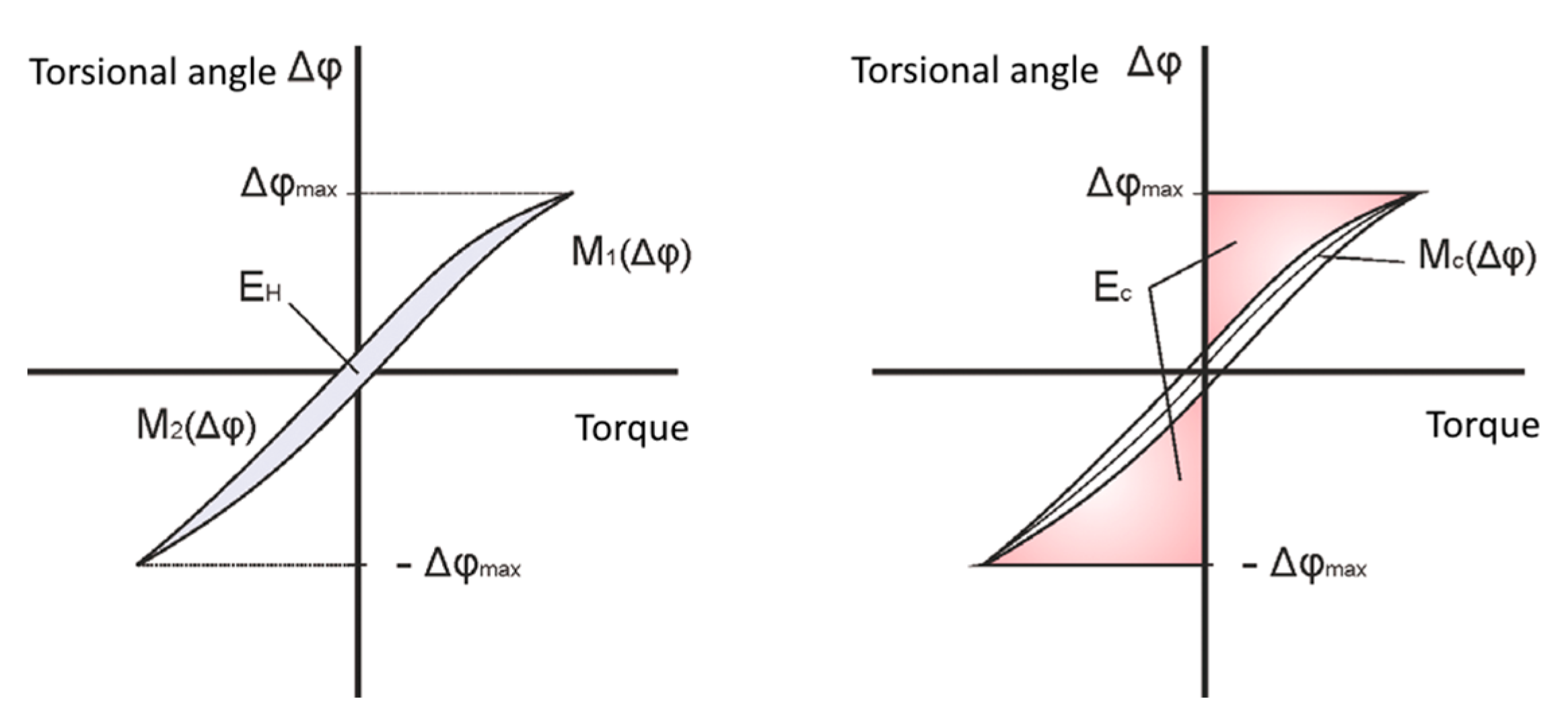
3.2. Dynamic Properties of Bearing Reducers of the TwinSpin Class

The disadvantage of the classic cycloid transmission lies in the ripple of the output torque at constant speed. The rotation of two wheels is described as rolling off of each other, with the axis of one of the wheels shifted by the value of eccentricity, which causes the resulting ripple of the cycloid gearbox torque. In reality, though, the interactions in the gearbox are much more complex. Under the effect of the eccentric shaft, the SPINEA gearbox’s trochoid wheels shift by 180° with respect to each other. As a result of the precise trochoid gear profile, almost 50% of the cogs of one wheel are engaged at the same time, which significantly flattens this unwanted ripple. In addition, the gearbox includes axial-radial bearings that, with the very precise trochoid gearing of the gearbox itself, predestine the TwinSpin gearbox from SPINEA to be used in precision-intensive applications, applications with high torque capacity, low dead run, and high rigidity of the compact design [19]. Technical parameters of the bearing reducer of the TwinSpin class are listed in Table 1.
In order to meet the requirement of increasing the reliability of the device, information must be available about the actual state of the object examined (BR). This can also eliminate hidden, less serious defects, which can later develop into a malfunction. Based on this information, timely intervention can be made and prevent malfunction at the most appropriate time, which can significantly affect the entire production process.
If the input shaft and the case are fixed and a torque is applied to the output flange, then the load diagram has the shape of a hysteresis curve (Figure 2). Lost motion (LM) is a pitch angle of the output flange at ±3% nominal torque measured on the centerline of the hysteresis curve (Figure 2).
Torsional stiffness (kt) is defined as follows:
k t = c d N m / a r c m i n
The torsional stiffness values are statistical values for the particular reduction ratio. The hysteresis characteristic of TwinSpin TS 140-139-TB with the lost motion under 0.5 [arcmin] is illustrated in Figure 3.
In their respective publications [19,20], the authors discuss dynamic properties of the TwinSpin gearbox, which is a linear three-weight system with a flexible coupling. In terms of position control, it is necessary to know or identify the nonlinearities that affect the resulting positioning accuracy. As a result of the imperfection in the production of the trochoid wheels and the gearbox support body, the so-called angular transmission error of the gearbox occurs, shown in Figure 4. This phenomenon results in a positioning error, which can be understood as the volatility of the already mentioned theoretical value of the ith transmission ratio.
Depending on the position of the output shaft and the angular transmission error value, the following equations [19,20,21] apply to the position and torque, respectively:
φ ˙ i n = i ( φ o u t ) φ ˙ o u t
M a = M o u t i ( φ o u t )
The exact gear ratio i(ϕout) in the defined position of the rotated output flange cannot be accurately described by a simple equation (φin, φout are the turning angles of the wheels). Due to the periodicity of the angular transmission error having exceeded at least one revolution of the output flange, this error can be characterized by the Fourier series:
u φ o u t = i t h + j = 1 n u A j c o s ( f j φ o u t + b j )
where f is the frequency of rotation, ith is the theoretical value of the transmission ratio, A represents the amplitude, and b is the phase deviation.
The angular transmission error (ATEM) is an important characteristic of rotary modules and refers to the deviation between the actual output rotation angle and the theoretical output rotation angle. ATEM is typically measured in degrees or arcminutes, and it is a critical factor for ensuring the accuracy, uniformity, and repeatability of the output position of the rotary module. ATEM is influenced by several factors, such as the design of the rotary module, the coupling mechanism used to connect the input and output shafts, the quality of the bearings, and the machining tolerances of the various components. In general, a low ATEM value is desirable, as it indicates that the rotary module can deliver more accurate and precise output positions. Therefore, it is important to carefully consider the ATEM specifications of rotary modules when selecting them for various applications that require high precision and accuracy. Understanding the factors that influence ATEM can help in the design and manufacturing process of rotary modules to achieve better performance and minimize errors. The angular transmission error of the high-precision TwinSpin reducer is less than 1 arcmin. Figure 4 shows an example of an angular transmission error measured on a particular high-precision reducer TS 140-139-TB. The impact of the load on the accuracy of angular transmission is relatively low.
The measurement methodology consists of reaching a position of 720° at the speed of rotation of the reducer’s output flange of 6°/s. Subsequently, the reducer reaches the 0° position at the same speed of the output flange. This ensures 360° rotation of all rotating components. The ATEM is measured in the load-free state with the input gear speed equal to the gear ratio. The speed of the output flange of the reducer is evaluated by 360° in units [arcsec].
The measurement evaluates the amplitude of error deflection as the fluctuation of the “Peak to Peak” deflection in relation to the angle of rotation of the BR output flange.
The measurement takes place in two directions:
  • rotation of the output flange in one direction by 360°—marked CW—and
  • rotation of the output flange in the opposite direction by 360°—marked CCW.
The investigated object—the reducer—was fastened in the MTS frame in a vertical position. The measurement was carried out in a load-free state.
The measurement of hysteresis lies in detecting the difference between the actual position of the output flange and the desired position, depending on the magnitude of the torque applied at the braked input side of the reducer. The hysteresis of the torsional rotation of the BR output flange as an angular difference is defined by the hysteresis loop in units [arcmin]. The hysteresis characteristics offer information on the static and dynamic profile of the examined gearbox. Torsional stiffness, backlash in the cogs, and information on positioning accuracy are among the most significant variables that can be obtained from measuring the hysteresis of a given gearbox. Hysteresis is a phenomenon that describes the lagging or delayed response of a system to a changing input or stimulus. In the context of gearboxes and positioning systems, hysteresis can cause positioning errors, reduce accuracy, and increase wear on the components of the system. The hysteresis curve is a graphical representation of the relationship between the input and output of a system, which can help with visualization of the magnitude and direction of the hysteresis effect (Figure 3). It typically shows the output response of the system as a function of the input as the input is gradually increased and then decreased while keeping all other conditions constant. Reducing hysteresis is often a key goal in the design and optimization of gearboxes and positioning systems, as it can improve positioning accuracy, reduce wear, and increase overall performance. Techniques such as optimizing the design of the gearbox components, using high-quality materials and lubricants, and carefully controlling operating conditions can help to minimize hysteresis and improve the performance of the system [19].
In [20], the relationship between gearbox hysteresis and torsional stiffness efficiency nt is described as follows:
n t = 1 E h 2 E c
where Eh is the lost energy and Ec represents the energy of the undampened spring, while the following applies to these energies:
E h = φ m a x φ m a x M 1 φ d φ φ m a x φ m a x M 2 φ d φ
E c = φ m a x φ m a x M c φ d φ
where M1 and M2 are the torque values of the upper or lower branch of the hysteresis curve, respectively, and Mc is the torque corresponding to the loss-free elastic torque of the spring (see Figure 5).
For research purposes, as part of the process of measuring static and dynamic parameters of bearings and high-precision bearing reducers (BR), a mechatronic troubleshooting system (MTS) has been designed. Drawing on the criteria proposed for selection of actuators, a measuring device designated as MTS 4.0 (Figure 6) has been designed. The troubleshooting device is the property of our partner—SPINEA Technologies, Ltd., Prešov. All measurements were carried out on the premises of SPINEA Technologies, Ltd.

3.3. Tribological Properties and Lubrication of Bearing Reducer Mechanisms

Lubricant (oil, grease lubricant) in the reduction mechanism can be considered one of the most important components affecting trouble-free operation of the bearing reducer. The aim is to ensure perfect lubrication of friction points, or effective protection against friction and wear, as well as against the consequences of these phenomena (contact corrosion). In addition, lubricants must meet the following criteria:
  • reduction of mechanical energy losses and improvement of the mechanical efficiency of the system,
  • reduction or suppression of wear and its harmful effects on the tribological system, and
  • improvement of heat dissipation and sufficient cooling.
The quality of the lubricant (grease and oil) applied to the bearing reducer affects its trouble-free operation and service life. The reliability of the reduction mechanism also depends on other technical conditions that are necessary for proper functioning of the technical system. One such condition is cleanliness. Cleanliness is an essential condition that must be met in order for the reduction mechanism, as well as the entire mechatronic system, to work properly and reliably throughout its lifetime. The most common damage to transmission mechanisms occurs due to bearing damage and gear damage. The reasons for this need to be attributed to the fact that in such transmission mechanisms, there is a high pressure load (Hertz pressure), which leads to the formation of small fragments—particles—that are the cause of bearing damage. When the cogs are worn, this gives rise to the so-called micropitting, which occurs on the surface of the cog and causes a change in the cog profile, leading to greater cog noise and causing additional fatigue wear (macropitting, chipping, etc.). Micropitting may also occur in bearings. The influence of metal particles on oil degradation depends on the type of particles, e.g., Fe, Cu, etc. These particles can cause catalytic oxidation. In any reduction mechanism, there is a release of abrasive particles—the generation of the particles themselves. Such a system needs to be periodically monitored in order to achieve a certain equilibrium of the particles present so as to not cause fatal destruction of the reduction mechanism.
For measuring purposes, the COSMOS SDM-73measuring device was used. The device allows easy troubleshooting to determine the wear of bearings, gears, etc. The aim of the measurement was to determine the concentration of Fe particulate concentration after the run-in time and after operating 1000 h in the load configurations with mechanical weight. The method of particle detection and isolation by means of a magnetic analyzer allows detection of the intensity of wear and informs on the friction and wear process. It is the result of the fluid’s drift force and the magnetic forces that, when applied to an inspected oil sample, ensure that larger iron particles settle immediately upon inlet onto a glass slide that is conveniently located in a strong magnetic field generated by permanent magnets. Due to greater surface-to-volume ratio, particles of 1 to 2 μm flow more slowly and settle on the bottom of the glass slide, i.e., at the outflow of the analyzed sample from the glass slide (ppm—parts per million), the number of particles per 1 million other particles, or 0.0001%, or 1 mg of the substance in 1 L of solution. For example, 25 ppm means 25 millionths, i.e., 0.000025, or 45 × 10−6, or 0.0025%, or 0.025‰.

4. Experimental Methods

Assessment of the Current Technical Condition of Selected Bearing Reducer Samples by the Chosen Methods of Technical Troubleshooting

The research focused on the assessment and analysis of characteristic non-linear behavior of the kinematic structures of the selected high-precision bearing reducer. Our partner was interested in the analysis of the TS 050 class reducer’s technical condition after its approx. 1000 h in operation (Figure 1). We identified the state of abrasive particles in the lubricant, analyzed the state of the contact surfaces in the start-up process, and diagnosed the state of the lubricant and subsequently the state of the contact surfaces in the operational process. The conducted lubricant analysis was primarily focused on determining the optimal start-up time of a given BR and identification of abrasive particles that pass through during the start-up in the first hours of operation. During the start-up, significant wear occurs due to the contact of the respective surfaces of the transmission components. This condition persists until the individual components of the transmission mechanism have settled into operation. The same measurements were also carried out during operation in order to identify significant changes in the BR’s technical condition. Temperature changes were analyzed at the same time. Last, but not least, a correlation was sought between the total content of Fe (iron) particles in the oil and an increase in kinematic backlash in the engagement of cycloidal wheels and BR bearings.
Measurement of the TS 050 bearing reducer was carried out configured with a mechanical weight load on the arm on the mechatronic troubleshooting system. Measurements of the examined object were carried out on 10 samples under 100% TR load and with a constant input rotation rate of 1000 rpm over a period of 1000 h. The measurement parameters are listed in Table 2.
The so-called bump test was done repeatedly on the BR. The bump test is a type of frequency response test that is commonly used to identify the natural frequencies and damping ratios of a mechanical system, such as a gearbox or a structure. In the context of the BR, the bump test would involve applying a sudden, short-duration impulse or “bump” to the system and measuring the resulting response in the torsional and tilting directions. BR was measured at a constant rotational frequency of 1000 rpm at the input, under a sinusoidal load (weight on the arm), in both directions of rotation (CW, CCW). A vibration sensor was used for the measurement PBC 356B18. At the same time, the measurement of absolute vibrations was carried out during a smooth change of the input speed, in the ranges of 0 to 2000 rpm and 0 to 3000 rpm, with the aim of monitoring the amplification of the oscillation of the output arm. Subsequent to the 1000-h operation, measurements of the LM and H parameters, which could have been affected by the start-up mode, were taken again. Due to the comparability of the individual results before and after the start-up and after 1000 h of operation, a mark was created on each BR across the position of the BR support body and the position of the output flange. In this simple way, a relevant assessment of the technical condition of the measured parameters was achieved. Graphed representation of the course of the LM and H measurements of the selected TS 050-63, s/n 1911, is shown in Figure 7.
The TS 050 troubleshooting has been extended by another technical parameter reflecting the kinematic accuracy of the BR, namely the ATEM parameter. It was evaluated between the position sensors located on the input and output sides of the BR, in the load-free state at the BR rotation speed of 6°/s, at a rotation of the BR output of 360° in both directions (CW, CCW). A summary of the ATEM values measured in the individual BR samples after a 48-h start-up and after 1000 h in operation is given in Table 3. The ATEM graphs for the TS 050 bearing reducer with the serial number 1901 are shown in Figure 8, Figure 9, Figure 10 and Figure 11. Testing was done 5 days a week, 24 h a day.
The measurement of the concentration of solid Fe particles was carried out after the start-up time and after the 1000-h operation in the configuration featuring a load (a mechanical weight) in accordance with the conditions specified in Table 2. Castrol Tribol GR TT1 PD lubricant was applied to the BR. The analysis of the lubricant was done using the evaluation device Cosmos SDM-72. The measured values are listed in Table 4.
Table 5 includes a record of the measured values of the natural frequencies of the bearing reducer BR 050 after 1000 h in operation.
In order to assess the levels of HF (high frequency) vibration, measurements and analysis of selected troubleshooting methods were also carried out as follows:
  • Acceleration, EnvAcc up to 10 kHz for assessing the quality of microgeometry of the contact surfaces (bearings, gearing)
  • EnvAcc up to 20 kHz and HFD up to 40 kHz for friction mode and quality assessment—bearing capacity of oil film.
The operating condition of the TS 050 reducers (s/n 1902–s/n 1910) can be assessed as good or satisfactory for input speeds of 2000 and 3000 rpm, respectively, based on the assessment of the measured high-frequency vibrations. The exception is the TS 050 s/n 1901 reducer, where the vibrations exceed the allowed limit specified in Alarm 1 (see Table 6).
With respect to overall measured vibration values, it was necessary to identify the recommended limits with respect to the requirements of technical standard STN ISO 10816-3(6). For different operating modes of the machine (considering speed, loading, and performance) it is possible to set the warning limits (alarms) also on the basis of general recommendations (signal increase by 200% compared to reference value).
Default alarm levels:
  • ALARM 1—Warning: 4.0 (mm/s g gE)
  • ALARM 2—Danger: 7.1 (mm/s g gE)
Figure 12 and Figure 13 show En4 time records for the CW and CCW measurement methods on the examined TS 050 reducer, s/n 1901.
In terms of the FFT spectrum with Acc up to 16 kHz—a comparison of the signal for the speed of 3000 rpm, after 1000 h in operation—the TS 050-63 bearing reducer shows an improvement in high-frequency vibrations by about 30% in the frequency range above 7 kHz. However, the vibration value continues to exceed Alarm 1, especially during the load time of the power transmission (Figure 14 and Figure 15).
Figure 16 and Figure 17 shows plotted records of mechanical vibrations in the frequency range up to 1 kHz, measurements on the BR TS 050 support body with the input speed of 2000 rpm. Time records indicate a sinusoidal effect of the weight load in the transfer of mechanical power. The measured values are related to the increase in torsional vibrations on the output arm. The gearbox shows minimal deterioration after 1000 h. On the time record, a different response to the load can be observed at the time of lifting and lowering the arm (alternation of lighter and darker vibrating areas under the curve).
Figure 18 and Figure 19 show the dependence of vibration on the input speed in the radial and axial directions.
In the case of radial recording, the critical speed (natural torsional frequency) is identifiable around the input speed of 750 rpm. In the axial direction, the critical speed (natural tilting frequency) is at about 1240 rpm of the input speed.
The measurement of temperature changes on the surface of the BR support body was performed using an Alnico sensor. This technique is useful in monitoring the temperature of the BR support body, as temperature changes can affect the performance and reliability of the system. Excessive temperature can cause thermal expansion, which can lead to misalignments, distortions, or even failures in the system. By monitoring the temperature changes, engineers can identify any potential issues and take appropriate measures to prevent or mitigate them. The alarm value was set to 60 °C. The temperature was measured in hourly intervals. The temperature alarm value was not exceeded during the measurements. The sum values of the BR surface temperatures over the first 48 h of measurements are shown in Figure 20.

5. Results and Discussion

After the start-up mode with a load and finding of the initial BR state, measurements of the start-up torque, hysteresis, lost motion, and temperatures; analysis of the presence of abrasive Fe particles; vibration measurement in the tilt and torsion directions; and measurement of temperature changes were carried out on the examined object, the TS 050 bearing reducer. Prior to the stress test itself, other measurements were made to determine the angular transmission error.
The measurements were done on 10 TS 050-63 reducer samples. The examined object was burdened with a load of the rated output torque TR = 18 Nm during a 1000-h long operation. After the end of a given period of operation under a load, repeated measurements were made to determine the BR’s natural frequencies, as were the H, LM, and ATEM parameter measurements, the test for the presence of abrasive particles, HF vibration measurement, FFT spectrum Acc up to 16 kHz, vibration up to 1 kHz, and critical speed measurement.
Based on the measurements and the subsequent analyses, it is possible to state the following:
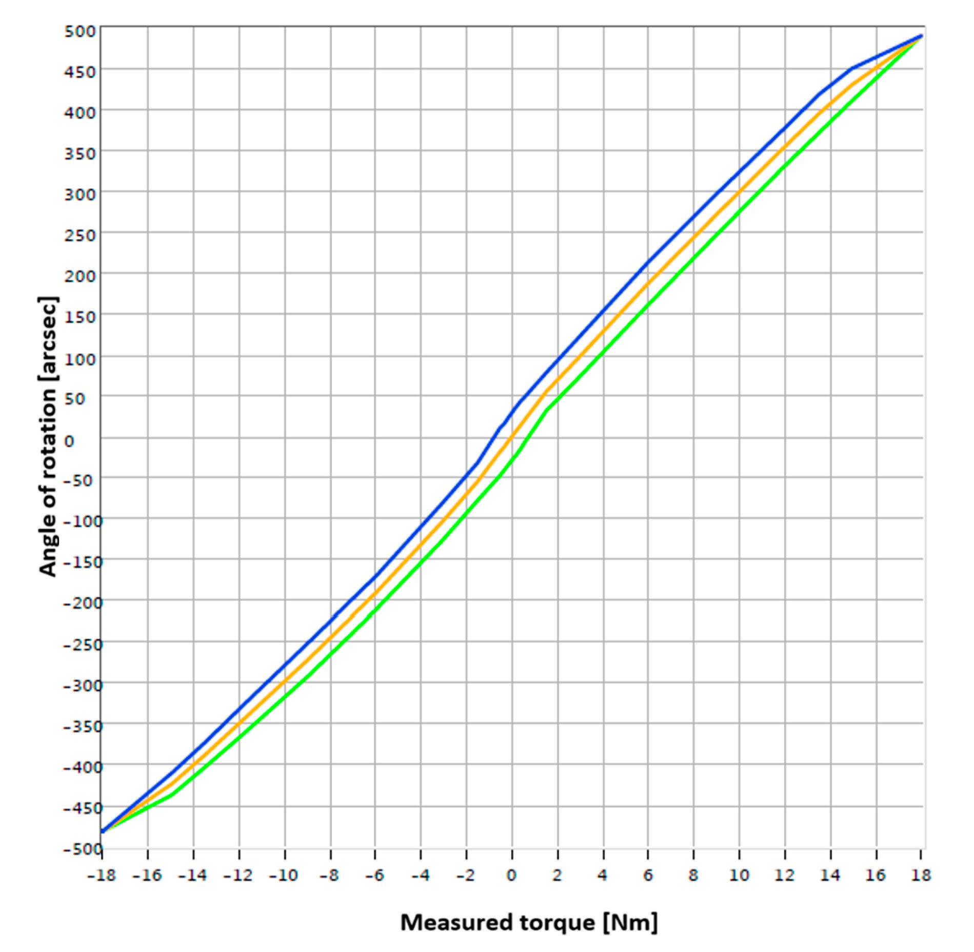
  • In terms of measurement of lost motion, hysteresis: The monitored parameters of post-operative hysteresis showed a slight increase in values. The LM parameter showed no significant change from the baseline value after 1000 h of operation.
  • In terms of temperature measurement: The alarm value of 60 °C was not exceeded during the measurements.
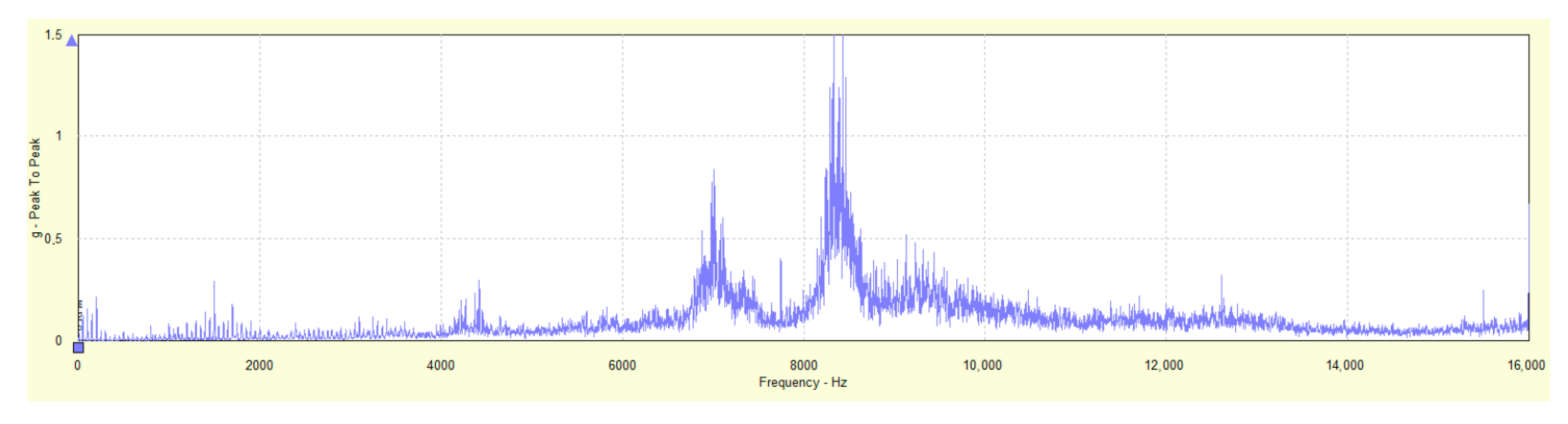
  • In terms of vibration measurement: A decrease in torsional stiffness was noted after 1000 h of operation. This was confirmed by measuring natural frequencies, which showed a decrease of about 2 Hz in the torsion direction. Reduced natural frequency has a positive effect on the overall vibration. No resonance is generated. The tested samples continued to be free of load peaks—no sign of metallic contact. There was an overall drop in vibration for the test speeds of 2000 rpm and 3000 rpm, respectively. The HF vibration analysis confirmed the satisfactory technical condition of the TS 050 bearing reducer samples in nine out of ten cases.
HF vibrations were recorded in the sample with the serial number of 1901, identifying a condition of non-conformity, mainly in terms of friction assessment at the input component speed BR 3000 rpm. Long-term tests have shown that there is gradual damage to the output bearings and thus to the reducer itself. It is recommended to dismantle and check the internal dimensions and surfaces of the sample in question.
The critical input speed was determined for the BR measured. In the axial direction, the value is about 1240 rpm, and in the radial direction, the speed accounts for about 750 rpm. When measuring vibrations up to 1 kHz, it is possible to see from the time record how the measured mechanical system reacts to the load when transmitting mechanical power with a load on the arm. The time record shows a different reaction at the time of lifting and lowering the arm with the load (alternation of lighter and darker area under the curve).
  • In terms of assessing the lubricant condition: After the initial phase of relative start-up and 1000 h of operation, the filling of Castrol Tribol GR TT1 PD continued to show a satisfactory state of the abrasive Fe particles content. All sample values were below the recommended limit.
  • In terms of ATEM measurement: The monitored ATEM parameters showed a slight increase in values after initial start-up and 1000 h of operation.

6. Conclusions

The high-precision TwinSpin gearbox is a combination of a transmission mechanism and an output bearing. Inside, it contains both slow- and high-speed bearings along with cycloidal gearing. Typical for the TwinSpin gearbox is its absolutely balanced internal design, which, despite containing excentres as a vibration generator, eliminates their resulting impact during rotation through their careful placement to achieve that effect. The transmission mechanism itself is dominated by rolling friction, which in its essence does not generate vibrations, as is the case with shear friction. Balance and low vibration are also achieved by a single-stage transmission, which also achieves high gear ratios. Dimensional tolerances, geometric accuracy, and roughness are extremely low, below 1 µm. The cycloid gearbox transfers mechanical power from the servo drive to the output arm through individual components—contact surfaces (bearings, cogged gears, etc.). For reliable operation, it is extremely important that excessive wear (adhesive/abrasive Fe particles) does not occur on the contact surfaces during the entire life of the gearbox (manipulator/robot).
In order to meet the requirement of increased reliability, information must be available about the actual state of the object examined (BR). This can also eliminate hidden, less serious defects, which can later develop into a malfunction.
The present research was aimed at identifying the current BR state during its start-up phase and after about 1000 h of operation. The state of the presence of the abrasive particles in the lubricant was identified, and, subsequently, the state of contact surfaces after the start-up and the operational phase was assessed. In practice, we are not often approached with the requirement to sample lubricants and check them at such intervals. However, since this is a relatively small BR design in which the lubricant content is low (in milliliters—the quantity of lubricant collected was in the same volume), it was very important to do the analysis. Lubricant analyses were primarily aimed at determining the optimal start-up time for the given BR. Abrasive Fe particles, which are introduced during the start-up in the first hours of operation, have been identified. The finding that significant wear and tear occurs during the first hours of operation due to contact of the respective surfaces of the transmission components has been confirmed.
The start-up time of cycloid bearing reducers varies depending on their design, use, and operating conditions. In general, cycloidal bearing reducers have a higher start-up time than conventional cogged gearboxes. An important factor is also the quality and type of the bearings used, which can affect the operational reliability and service life of the reducer. Based on the analysis, we can confirm the recommendations for the user of the bearing reducer of the TwinSpin class to run the reducer for at least 48 h under at least a 50% load of the nominal torque and a maximum speed of 1000 rpm. In order to ensure high service life and operational reliability, it is recommended to replace the entire oil filling after the first 100 h of operation after the start-up with lubricant in the form of technical oil. Based on recommendations from the reducer manufacturer, if the lubricant is grease, it is possible to replace the grease only by completely dismantling the BR. Grease replenishment should be carried out after 1000 h of operation.
The operating problems of bearing cycloid reducers can be caused by various factors that can interact with each other. Some of the most common operational problems are [22,23,24,25,26]:
  • Wear and tear of the cogs—A cycloid gear system is prone to wear and tear due to high pressure and friction between the gear cogs. Wear and tear may lead to impaired torque transmission accuracy and impaired torque efficiency.
  • Incorrect mounting—Incorrect mounting may cause various problems, such as damage to the gear, disruption of the gear geometry, and deterioration of its efficiency.
  • Excessive load—the cycloid bearing reducer is designed for a certain load, and exceeding this limit may cause damage to the gear cogs and lead to a gearbox failure.
  • Insufficient lubrication—Insufficient or contaminated lubricant may cause gear wear and deterioration of transmission efficiency.
  • Noise—a cycloid gear system can be significantly noisy in operation, which can be undesirable in specific applications.
  • Vibration—A cycloid gear system may tend to vibrate. Vibration may negatively affect torque transmission accuracy and impair gearbox efficiency.
To prevent these problems and ensure operational reliability and more efficient operation of the cycloid bearing reducer, regular maintenance and inspection is of utmost importance.

Author Contributions

Conceptualization, P.B. and M.K.; methodology, D.P., P.B. and M.K.; software, P.B. and M.K.; validation, M.K. and D.P.; formal analysis, P.B., M.K. and D.P.; investigation, P.B., M.K. and D.P.; resources, D.P.; data curation, P.B. and M.K.; writing—original draft preparation, P.B.; writing—review and editing, P.B.; visualization, P.B.; supervision, P.B.; project administration, M.K.; funding acquisition, P.B. All authors have read and agreed to the published version of the manuscript.

Funding

The article was prepared thanks to the support of the Ministry of Education, Science, Research, and Sport of the Slovak Republic through the grants VEGA number VEGA 1/0026/22 and KEGA number KEGA 002TUKE-4/2023.

Data Availability Statement

The data presented in this study are available on request from the corresponding author. The data are not publicly available due to restrictions of the funding source.

Conflicts of Interest

The authors declare no conflict of interest.

Abbreviations

ACCdeflection ACCeleration
ATEMAngular Transmission Error
CCWCounterclockwise
CWClockwise
FFTFast Fourier Transformation
HHysteresis
HFHigh Frequency
LMLost Motion
BRBearing Reducer
MTSMechatronic Troubleshooting System
ppmparts per million
RVRotate Vector
HPRHigh Precision Reducer
HDHarmonic Drive
RTERotational Transmission Error
GRGear Ratio

References

  1. Baron, P.; Kocisko, M.; Dobransky, J.; Pollak, M.; Cmorej, T. Research and correlation of diagnostic methods for assessment of the state of oil filling in cycloid gearbox. Adv. Mater. Sci. Eng. 2015, 2015, 597841. [Google Scholar] [CrossRef]
  2. Kocisko, M.; Pollák, M.; Töröková, M.; Baron, P.; Paulišin, D.; Kundrík, J. Determination of Methodology and Research of the Influence of the Trial Run of High-Precision Reducers on the Change of Their Characterizing Properties. Appl. Sci. 2021, 11, 3859. [Google Scholar] [CrossRef]
  3. Olejarova, S.; Dobransky, J.; Svetlik, J.; Pituk, M. Measurements and evaluation of measurements of vibrations in steel milling process. Measurement 2017, 106, 18–25. [Google Scholar] [CrossRef]
  4. Krolczyk, G.; Legutko, S.; Stoic, A. Influence of the cutting parameters and conditions onto surface hardness of duplex stainless steel after turning. Teh. Vjesn. Tech. Gaz. 2013, 20, 1077–1080. [Google Scholar]
  5. Strutynskyi, S.; Semenchuk, R. Investigation of the Accuracy of the Manipulator of the Robotic Complex Constructed on the Basis of Cycloidal Transmission. Technol. Audit. Prod. Reserves. 2021, 4, 6–14. [Google Scholar] [CrossRef]
  6. Semjon, J.; Janos, R.; Tuleja, P.; Balaz, V. Procedure selection bearing reducer twinspin for robotic arm. Appl. Mech. Mater. 2013, 245, 261–266. [Google Scholar] [CrossRef]
  7. Lopez Garcia, P.; Crispel, S.; Saerens, E.; Verstraten, T.; Lefeber, D. Compact Gearboxes for modern Robotics: A Review. Front. Robot. AI 2020, 7, 103. [Google Scholar] [CrossRef]
  8. Pawelski, Z.; Zdziennicki, Z.; Uszpolewicz, G. Properties of a three disc cycloid gear as a result of bench test. J. KONES 2018, 25, 269–280. [Google Scholar] [CrossRef]
  9. Zareba, R.; Mazur, T.; Olejarczyk, K.; Bzinkowski, D. Measurement of the Cycloidal Drive Sleeves and Pins. Mechanika 2021, 27, 6. [Google Scholar] [CrossRef]
  10. Blagojevic, M.; Marjanovic, N.; Djordjevic, Z.; Stojanovic, B.; Disic, A. A new design of a two-stage cycloidal speed reducer. Des. Innov. 2011, 133, 085001. [Google Scholar] [CrossRef]
  11. Hsieh, C.F.; Jian, W.S. The effect on dynamics of using various transmission designs for two-stage cycloidal speed reducers. Proc. Inst. Mech. Eng. Part C J. Mech. Eng. Sci. 2015, 230, 4. [Google Scholar] [CrossRef]
  12. Tsai, S.J.; Chang, L.C.; Huang, C.H. Design and analysis of a three-stage cycloidal planetary gear drive for high reduction ratio. In Proceedings of the JSME International Conference on Motion and Power Transmissions, Kyoto, Japan, 28 February–3 March 2017; The Japan Society of Mechanical Engineers: Tokyo, Japan, 2017. [Google Scholar] [CrossRef]
  13. Pham, A.D.; Ahn, H.J. High precision reducers for industrial robots driving 4th industrial revolution: State of arts, analysis, design, performance evaluation and perspective. Int. J. Precis. Eng. Manuf. Green Technol. 2018, 5, 519–533. [Google Scholar] [CrossRef]
  14. Blagojević, M.; Matejić, M.; Kostić, N. Dynamic behaviour of a two-stage cycloidal speed reducer of a new design concept. Teh. Vjesn. 2018, 25 (Suppl. S2), 291–298. [Google Scholar] [CrossRef]
  15. Yang, M.; Zhang, D.; Cheng, C.; Han, X. Reliability-based design optimization for RV reducer with experimental constraint. Struct. Multidiscip. Optim. 2021, 63, 2047–2064. [Google Scholar] [CrossRef]
  16. Bednarczyk, S. Analysis of the cycloidal reducer output mechanism while taking into account machining deviations. Proc. Inst. Mech. Eng. Part C J. Mech. Eng. Sci. 2021, 235, 7299–7313. [Google Scholar] [CrossRef]
  17. Matejic, M.; Goluza, V.; Vasic, M.; Blagojevic, M. Analysis of two-stage cycloid speed reducers dimensions and efficiency. In Proceedings of the KOD 2021: Machine and Industrial Design in Mechanical Engineering, Novi Sad, Serbia, 10–12 June 2021; pp. 171–181. [Google Scholar] [CrossRef]
  18. Maccioni, L.; Concli, F.; Blagojevic, M. A new three-stage gearbox concept for high reduction ratios: Use of a nested-cycloidal architecture to increase the power density. Mech. Mach. Theory 2023, 181, 105203. [Google Scholar] [CrossRef]
  19. Hric, M.; Fedák, V.; Durovský, F. Vplyv nelinearít cykloidnej prevodovky na presnosť polohovania. ATP J. 2012, 9, 42–44. [Google Scholar]
  20. Balara, M. Ložiskový Reduktor a Jeho Matematický Model. Sekel 2007 Principia Cybernetica 2007; ČVUT: Prague, Czech Republic, 2007; p. 6. ISBN 9788001038048. [Google Scholar]
  21. Olsson, H.; Astrom, K.J.; de Wit, C.C.; Gafvert, M.; Lischinsky, P. Friction Models and Friction Compensation. Eur. J. Control 1998, 4, 176–195. [Google Scholar] [CrossRef]
  22. Pham, A.D.; Ahn, H.J. Efficiency analysis of a cycloid reducer considering tolerance. J. Frict. Wear 2017, 38, 490–496. [Google Scholar] [CrossRef]
  23. Terakawa, T.; Komori, M.; Morita, Y. Motion analysis and experiments of reducer-integrated motor using strain wave gearing system. In Proceedings of the ASME 2018 International Design Engineering Technical Conferences and Computers and Information in Engineering Conference, Quebec, QC, Canada, 26–29 August 2018; pp. 1–6. [Google Scholar] [CrossRef]
  24. Gorla, C.; Davoli, P.; Rosa, F.; Longoni, C.; Chiozzi, F.; Samarani, A. Theoretical and experimental analysis of a cycloidal speed reducer. J. Mech. Des. 2008, 130, 112604. [Google Scholar] [CrossRef]
  25. Yamada, S.; Fujimoto, H. Precise joint torque control method for two-inertia system with backlash using load-side encoder. IEEJ J. Ind. Appl. 2019, 8, 75–83. [Google Scholar] [CrossRef]
  26. Ren, Z.Y.; Mao, S.M.; Guo, W.C.; Guo, Z. Tooth modification and dynamic performance of the cycloidal drive. Mech. Syst. Signal Process. 2017, 85, 857–866. [Google Scholar] [CrossRef]
Figure 1. TwinSpin cycloid reducer from SPINEA (Prešov, Slovakia).
Machines 11 00595 g001
Figure 2. Hysteresis curve and the definition of stiffness TwinSpin bearing reducer [2].
Machines 11 00595 g002
Figure 3. Hysteresis curve of TS 140-139-TB.
Machines 11 00595 g003
Figure 4. Angular transmission error measurement—Model: TS 140-139-TB; load conditions: no load.
Machines 11 00595 g004
Figure 5. Typical values of the hysteresis curve [19].
Machines 11 00595 g005
Figure 6. Block diagram and design implementation of the mechatronic troubleshooting system.
Machines 11 00595 g006
Figure 7. The course of the TS-50-63, s/n 1901 hysteresis curve after 1000 h in operation.
Machines 11 00595 g007
Figure 8. ATEM, TS 050 s/n 1901 after a 48-h start-up, CW.
Machines 11 00595 g008
Figure 9. ATEM, TS 050 s/n 1901 after a 48-h start-up, CCW.
Machines 11 00595 g009
Figure 10. ATEM, TS 050 s/n 1901 after 1000 h in operation, CW.
Machines 11 00595 g010
Figure 11. ATEM, TS 050 s/n 1901 after 1000 h in operation, CCW.
Machines 11 00595 g011
Figure 12. Time records En4, TS 050 s/n 1901, 2000RPM, CW.
Machines 11 00595 g012
Figure 13. Time records En4, TS 050 s/n 1901, 2000 rpm, CCW.
Machines 11 00595 g013
Figure 14. FFT spectrum Acc up to 16 kHz, TS 050 s/n 1901, 3000 rpm, CW.
Machines 11 00595 g014
Figure 15. FFT spectrum Acc up to 16 kHz, TS 050 s/n 1901, 3000 rpm, CCW.
Machines 11 00595 g015
Figure 16. Recording of mechanical vibrations in the frequency range up to 1 kHz, BR TS 050, CW direction.
Machines 11 00595 g016
Figure 17. Recording of mechanical vibrations in the frequency range up to 1 kHz, BR TS 050, CCW direction.
Machines 11 00595 g017
Figure 18. Effect of input speed on TS 050-63 gearbox vibration, s/n 1901—radial direction.
Machines 11 00595 g018
Figure 19. Effect of input speed on TS 050-63 gearbox vibration, s/n 1901—axial direction.
Machines 11 00595 g019
Figure 20. Record of the course of temperature changes.
Machines 11 00595 g020
Table 1. Technical parameters of bearing reducers of the TwinSpin class.
TS 050TS 070TS 095TS 110
Gear ratioi47.6357.7543.9563.89
Rated output torqueTr [Nm]185085122
Acceleration and braking torqueTmax [Nm]36100170244
Permissible torque at emergency stopTem [Nm]90250425610
Rated input speednR [rpm]2000200020002000
Effective cycle speednef [rpm]3000250025002500, 2000
Max. permissible input speednmax [rpm]5000500045003900, 4500
Tilting stiffnessMt [Nm/arcmin]435140150
Torsional stiffnesskt [Nm/arcmin]2.571522
Max. dead runLM [arcmin]<1.5<1.5<1<1
ATEMATE [arcsec]-±36±20±20
HysteresisH [arcmin]<1.5<1.5<1.5<1.5
Weightm [kg]0.471.051.803.76
Table 2. Conditions of measurements applied to TS 050.
TS 050
Gear ratioi63
Rated output torque 100%TR [Nm]18
Rated output torque 50%TR 50% [Nm]9
Rated output speednR [rpm]1000
Vibration measurement-Yes
Lubricant analysis-Yes
Lubricant quantity[cm3]2.85
Lubricant type TT1 PD
Table 3. Measured ATEM values, TS 050 after a 48-h start-up and after 1000 h in operation.
No.Type BR/Serial No.ATEM after a 48-h Start-Up
CW/CCW [Arcmin]
ATEM after 1000 h in Operation CW/CCW [Arcmin]
1.TS 050/1901108.28/98.02111.53/105.34
2.TS 050/1902109.62/97.63112.02/101.25
3.TS 050/1903106.45/95.32107.18/96.81
4.TS 050/1904102.61/93.26104.11/94.54
5.TS 050/1905105.25/97.13106.09/98.75
6.TS 050/1906103.34/95.38105.28/95.63
7.TS 050/1907106.65/94.51107.20/97.32
8.TS 050/1908104.55/96.28105.85/97.32
9.TS 050/190997.69/86.54101.62/92.36
10.TS 050/1910107.32/98.87109.32/97.25
Table 4. Solid abrasive particle content values after a 1000-h long operation, TS 050.
No.Type BR/Serial No.Content Fe
(ppm)
after 48-h
Content Fe
(ppm)
after 1000-h
1.TS 050/19011622
2.TS 050/19021621
3.TS 050/19031723
4.TS 050/19041821
5.TS 050/19051822
6.TS 050/19061723
7.TS 050/19071620
8.TS 050/19081924
9.TS 050/19091722
10.TS 050/19101721
Table 5. Measured values of natural frequencies of the BR 050 bearing reducer after 1000 h in operation.
No.Type BR/Serial No.Lost Motion [Arcmin]Hysteresis
[Arcmin]
Natural Frequency Radially—Torsion [RPM/Hz]Natural Frequency Axially—Tipped [RPM/Hz]
1.TS 050/19010.520.49802/11.7 1320/22.0
2.TS 050/19020.660.60829/10.91214/21.4
3.TS 050/19030.570.57838/10.21248/20.2
4.TS 050/19040.530.69847/11.31273/19.3
5.TS 050/19050.550.52839/10.71236/20.1
6.TS 050/19060.550.47837/10.21251/20.9
7.TS 050/19070.690.49840/12.21238/21.1
8.TS 050/19080.560.642835/11.51245/19.6
9.TS 050/19090.510.60824/9.11213/20.9
10.TS 050/19100.650.53830/9.31214/21.8
Table 6. HF vibrations values measured in TS 050, serial no. 1901.
BR Type /Ser. No./Input SpeedOperating Time [Hours]DirectionHF High-Frequency
Vibration
Assessment of
the Operating
Status
Acc
(g)
En3
(gE)
En4
(gE)
HFD
(gHF)
TS 050/s.n.1901/2000 rpm48CW3.52.01.63.1Good
10002.71.81.62.0
48CCW3.02.31.73.6
10002.61.91.62.6
TS 050/s.n.1901/3000 rpm48CW3.84.14.45.3Unsatisfactory condition
10004.34.14.75.7
48CCW4.03.93.74.1
10004.44.13.85.9
CCW3.42.32.33.5
Disclaimer/Publisher’s Note: The statements, opinions and data contained in all publications are solely those of the individual author(s) and contributor(s) and not of MDPI and/or the editor(s). MDPI and/or the editor(s) disclaim responsibility for any injury to people or property resulting from any ideas, methods, instructions or products referred to in the content.

