
Study on Cage Wear of Railway Traction Motor Bearings Based on Analysis of Rolling Element Motion


Abstract
1. Introduction
2. Materials and Methods
2.1. Target Bearing
2.2. Method for Measuring Contact Force between Roller and Cage
2.3. Method for Dynamic Analysis for Determining Impulse
- I.
- Only the translational velocity of the roller changes when the roller and the cage make contact (the angular velocity of the cage is constant at a geometrically determined value.).
- II.
- In the no-load zone, the roller contacts the outer ring raceway due to centrifugal force and does not contact the inner ring raceway.
- III.
- The rotational speed of rollers is assumed to be constant at a theoretical value (The angular velocity of the roller is constant at a geometrically determined value.).
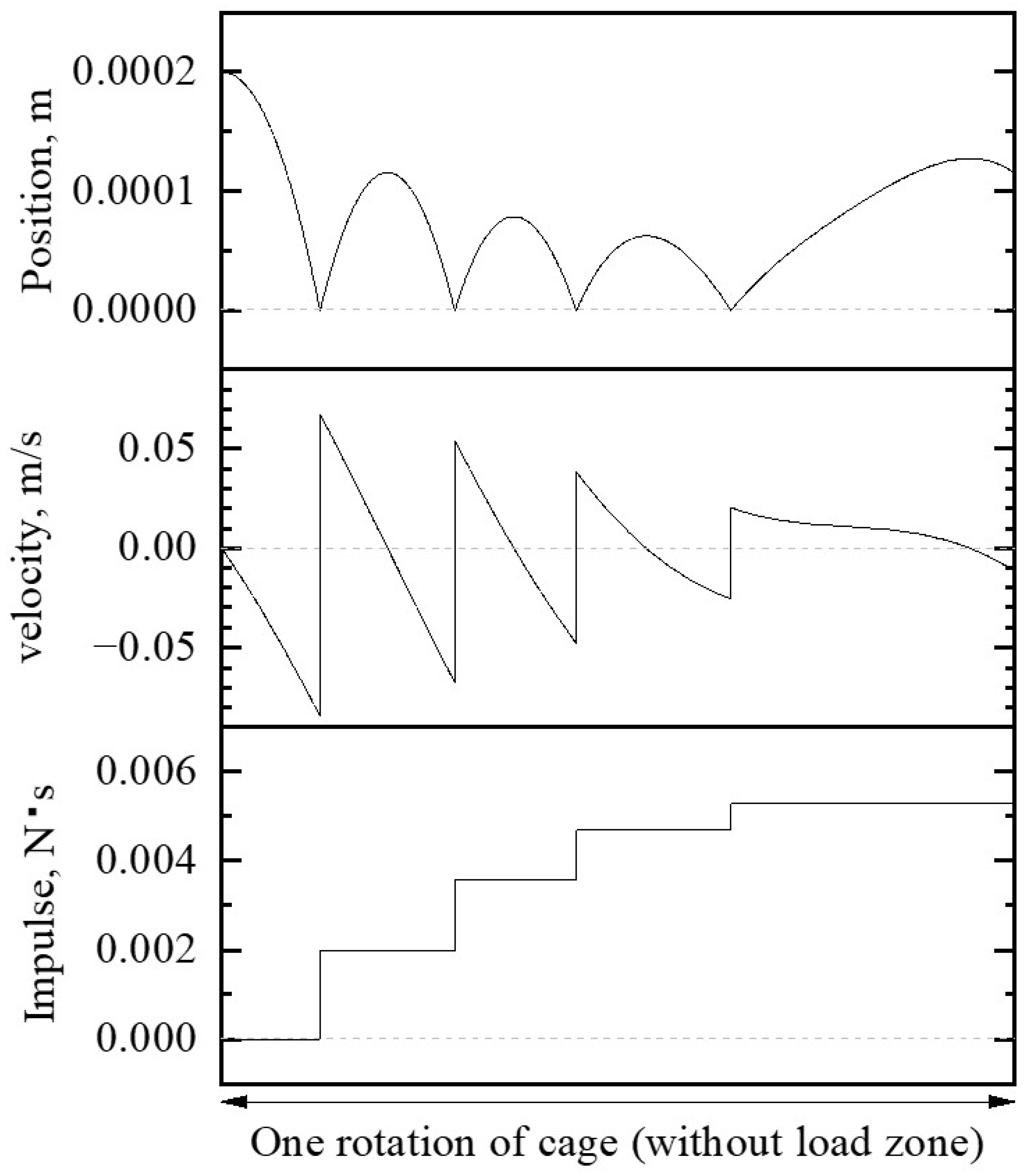
- (1)
- The roller within the no-load zone is located in the front of the cage pocket. This is because the roller accelerates the cage within the loading zone.
- (2)
- The orbital velocity of the roller is decelerated by and the tangential force of gravity. This causes the roller to move to the rear of the cage pocket. is generated by the oil film between the roller and the outer ring.
- (3)
- The roller contacts the rear of the cage pocket. is generated by the contact.
- (4)
- The roller bounces and moves to the front of the cage pocket.
- (5)
- When the relative velocity between the roller and the cage is zero, and the tangential forces of gravity act on the cage through the roller.
3. Results and Discussion
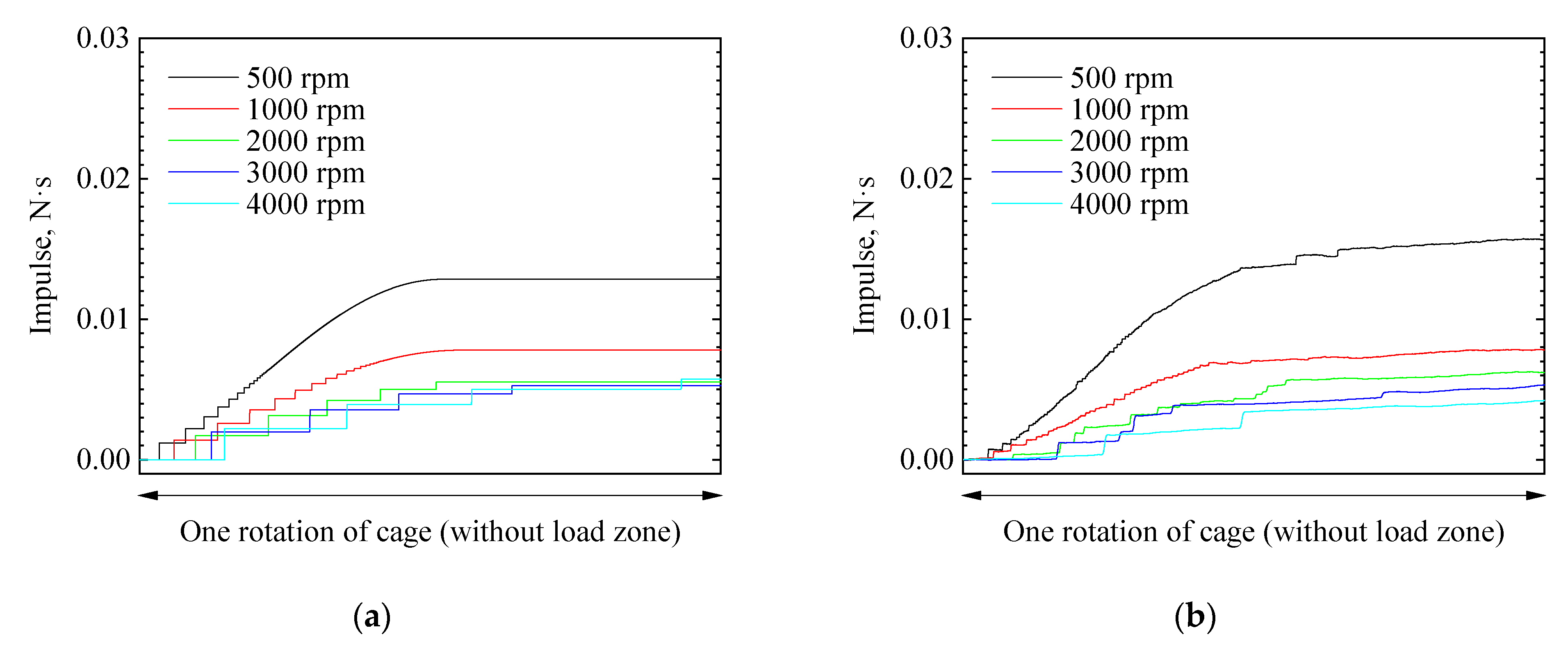
3.1. Comparison of Measurement and Dynamic Analysis
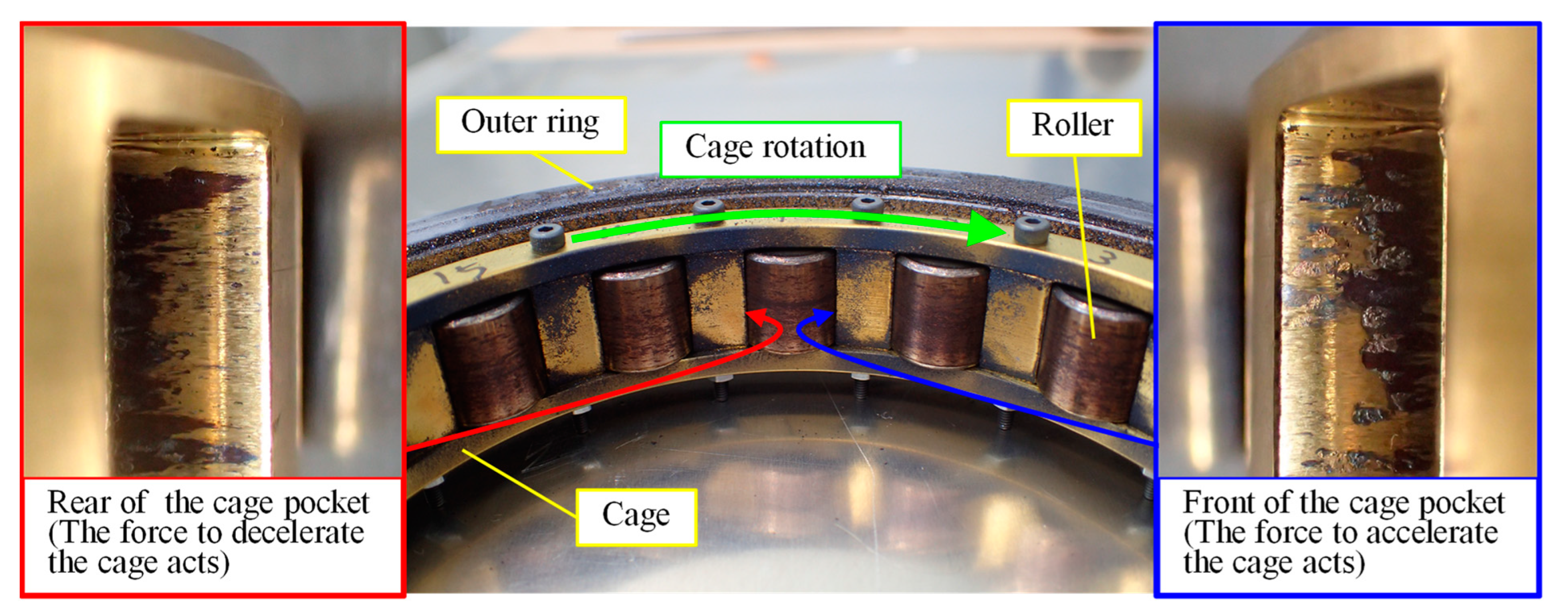
- (a)
- Force to accelerate the cage
- (b)
- Force to decelerate the cage
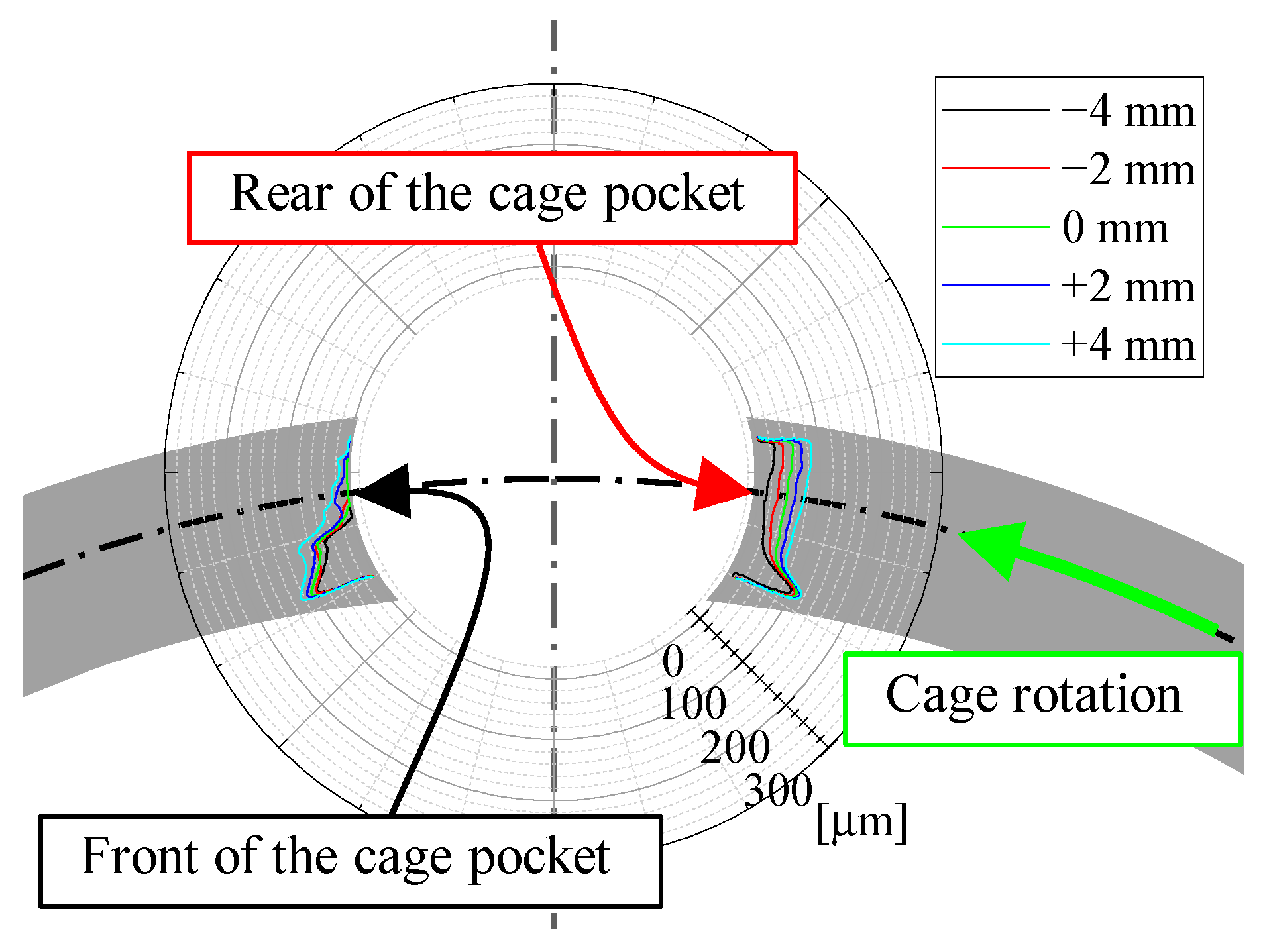
3.2. Determining Wear Modes
4. Conclusions
- The volume of cage wear is considered to be proportional to the impulse caused by contact, so a method was proposed to calculate this impulse. In this method, a model consisting only of a roller and a cage was constructed, and the movement of the roller relative to the cage was calculated. Using this method, the impulse caused by the contact was determined and compared with the measured results. The calculated results of the impulse were in close agreement with the measured values. Based on this, the analysis model in this paper is reasonable.
- The experiment was conducted to determine the wear mode of the cage. The results showed that the volume of cage wear is equal when the sum of the impulse is the same, regardless of the magnitude and frequency of the contact forces. In other words, the assumption that cage wear is proportional to the impulse is valid.
Author Contributions
Funding
Data Availability Statement
Conflicts of Interest
Nomenclature
| radius of roller (m) | |
| pitch circle radius of roller (m) | |
| inner radius of outer ring (m) | |
| mass of roller (kg) | |
| contact force between roller and cage (N) | |
| to accelerate cage (N) | |
| to decelerate cage (N) | |
| rotational speed of inner ring (rpm) | |
| volume of cage wear (m3) | |
| coefficient of wear | |
| contact force of two objects (N) | |
| sliding distance (m) | |
| hardness of softer material in two contact materials | |
| coefficient of impact wear | |
| kinetic energy at impact (J) | |
| coefficient of impact wear | |
| time (s) | |
| impulse caused by (=) (N·s) | |
| impulse caused by (=) (N·s) | |
| impulse caused by (=) (N·s) | |
| position of roller in cage pocket (m) | |
| pressure force exerted by oil film between roller and outer ring (N) | |
| normal force between roller and outer ring (N) | |
| rolling velocity (m/s) | |
| angular velocity of inner ring (rad/s) | |
| angular velocity of roller (=)) (rad/s) | |
| angular velocity of cage (=) (rad/s) | |
| constant in Equation (2) | |
| relative velocity of roller and cage before contact (m/s) | |
| relative velocity of roller and cage after contact (m/s) | |
| coefficient of restitution between roller and cage (=) | |
| half angle of load zone (°) | |
| angle of rotation (°) | |
| acceleration of gravity (m/s2) |
References
- Anderson, W.J.; Macka, E.F.; Nemeth, Z.N. Comparison of Performance of Experimental and Conventional Cage Designs and Materials for 75-Millimeter-Bore Cylindrical Roller Bearings at High Speed. U.S. Patent NACA-TR-1177, 1 January 1954. [Google Scholar]
- Wagner, F.C.; Burwell, J.T., Jr. New Retainer materials for Aircraft Gas Turbine Bearings. ASLE Trans. 1958, 1, 1–9. [Google Scholar] [CrossRef]
- Wen, B.; Wang, M.; Zhang, J.; Sun, W. Experimental Investigation of Clearance Influences on Cage Motion and Wear in Ball Bearings. Appl. Sci. 2021, 11, 11848. [Google Scholar] [CrossRef]
- Wen, B.; Li, Y.; Wang, M.; Yang, Y. Measurement for Lubricant Distribution in an Angular Contact Ball Bearing and Its Influence Investigation. Lubricants 2023, 11, 63. [Google Scholar] [CrossRef]
- Chen, C.; Deng, Z.; Wang, H.; He, T. Simulation of Friction Fault of Lightly Loaded Flywheel Bearing Cage and Its Fault Characteristics. Sensors 2022, 22, 8346. [Google Scholar] [CrossRef]
- Kudelina, K.; Baraškova, T.; Shirokova, V.; Vaimann, T.; Rassõlkin, A. Fault Detecting Accuracy of Mechanical Damages in Rolling Bearings. Machines 2022, 10, 86. [Google Scholar] [CrossRef]
- Pan, C.; Wang, C.; Zhao, Y.; Cao, G. Study on design and simulation of a novel isolator cylindrical roller bearing. J. Mech. Sci. Technol. 2022, 36, 3851–3862. [Google Scholar] [CrossRef]
- Lundberg, G.; Palmgren, A. Dynamic Capacity of Rolling Bearings. J. Appl. Mech. 1949, 16, 165–172. [Google Scholar] [CrossRef]
- Kakuta, K. The Effects of Misalignment on the Forces Acting on the Retainer of Ball Bearings. J. Fluids Eng. 1964, 86, 449–454. [Google Scholar] [CrossRef]
- Stacke, L.-E.; Fritzson, D. Dynamic behaviour of rolling bearings: Simulations and experiments. Proc. Inst. Mech. Eng. Part J. J. Eng. Tribol. 2001, 215, 499–508. [Google Scholar] [CrossRef]
- Tada, S. Dynamic Analysis of Sound, Vibration and Motion of Cage in High Speed Ball Bearings. KOYO Eng. J. 2002, 160, 29–36. [Google Scholar]
- Chen, S.; Chen, X.; Li, Q.; Gu, J. Experimental Study on Cage Dynamic Characteristics of Angular Contact Ball Bearing in Acceleration and Deceleration Process. Tribol. Trans. 2021, 64, 42–52. [Google Scholar] [CrossRef]
- Gupta, P.K. Dynamics of Rolling-Element Bearings Part I: Cylindrical Roller Bearing Analysis. J. Lubr. Technol. 1979, 101, 293–302. [Google Scholar] [CrossRef]
- Gupta, P.K. Dynamics of Rolling-Element Bearings Part II: Cylindrical Roller Bearing Results. J. Lubr. Technol. 1979, 101, 305–311. [Google Scholar] [CrossRef]
- Gupta, P.K. Dynamics of Rolling-Element Bearings Part III: Ball Bearing Analysis. J. Lubr. Technol. 1979, 101, 312–318. [Google Scholar] [CrossRef]
- Gupta, P.K. Dynamics of Rolling-Element Bearings Part Ⅳ: Ball Bearing Results. J. Lubr. Technol. 1979, 101, 319–326. [Google Scholar] [CrossRef]
- Sakaguchi, T.; Harada, K. Dynamic Analysis of Cage Behavior in a Tapered Roller Bearing. J. Tribol. 2006, 128, 604–611. [Google Scholar] [CrossRef]
- Sakaguchi, T.; Harada, K. Dynamic Analysis of Cage Stress in Tapered Roller Bearings Using Component-Mode-Synthesis Method. J. Tribol. 2009, 131, 011102. [Google Scholar] [CrossRef]
- Weinzapfel, N.; Sadeghi, F. A discrete element approach for modeling cage flexibility in ball bearing dynamics simulations. J. Tribol. 2009, 131, 021102. [Google Scholar] [CrossRef]
- Ashtekar, A.; Sadeghi, F. A New Approach for Including Cage Flexibility in Dynamic Bearing Models by Using Combined Explicit Finite and Discrete Element Methods. J. Tribol. 2012, 134, 041502. [Google Scholar] [CrossRef]
- Suzuki, D.; Takahashi, K.; Itoigawa, F.; Maegawa, S. Contact forces between roller and cage pocket in cylindrical roller bearings (Consideration based on dynamic behavior between roller and cage). Trans. JSME 2022, 88, 22-00153. (In Japanese) [Google Scholar] [CrossRef]
- Archard, J.F. Contact and Rubbing of Flat Surfaces. J. Appl. Phys. 1953, 24, 981. [Google Scholar] [CrossRef]
- Dahiwal, R.; Thielen, S.; Sauer, B. Modeling and Simulation of Cage Wear in Solid-Lubricated Rolling Bearings. Tribol. Online 2020, 15, 25–35. [Google Scholar] [CrossRef]
- Gao, S.; Han, Q.; Zhou, N.; Zhang, F.; Yang, Z.; Chatterton, S.; Pennacchi, P. Dynamic and wear characteristics of self-lubricating bearing cage: Effects of cage pocket shape. Nonlinear Dyn. 2022, 110, 177–200. [Google Scholar] [CrossRef]
- Zhou, R.S.; Hoeprich, M.R. Torque of tapered roller bearings. J. Tribol. 1991, 113, 590–597. [Google Scholar] [CrossRef]
- Tatara, Y.; Moriwaki, N. Study on Impact of Equivalent Two Bodies: Coefficients of Restitution of Spheres of Brass, Lead, Glass, Porcelain and Agate, and the Material Properties. Bull. JSME 1982, 25, 631–637. [Google Scholar] [CrossRef]
- Lewis, R. A modelling technique for predicting compound impact wear. Wear 2007, 262, 1516–1521. [Google Scholar] [CrossRef]
- Komoriya, T.; Ichimura, R.; Kochi, T.; Yoshihara, M.; Sakai, M.; Dong, D.; Kimura, Y. Service Life of Lubricating Grease in Ball Bearings (Part 1) Behavior of Grease and Its Base Oil in a Ball Bearing. Tribol. Online 2021, 16, 236–245. [Google Scholar] [CrossRef]


| Bearing Type | Cylindrical Roller Bearing | |
|---|---|---|
| Bearing number | NU214 | |
| Inner diameter | 70 mm | |
| Outer diameter | 125 mm | |
| Width | 24 mm | |
| Radial clearance | 0.090–0.125 mm | |
| Pitch circle diameter of roller | 97.5 mm | |
| Number of rollers | 16 | |
| Roller diameter | 13 mm | |
| Length of roller | 13 mm | |
| Mass of roller | 13 g | |
| Cage guide | By rollers | |
| Material | Race rings Rollers | Bearing steel |
| Cage | High-strength brass | |
| Basic dynamic load rating | 83,500 N | |
| Rotational speed of inner ring | 500, 1000, 2000, 3000, 4000 rpm |
| Direction of rotation | Forward, reverse |
| Radial load | 970 N |
| Lubricant | Lithium complex soap grease |
| Rotational speed of inner ring | 6000 rpm |
| Rotational direction of inner ring | Forward |
| Radial load | 922 N |
| Lubricant | Lithium complex soap grease 0.1 g |
| Data for This Paper | Data for Reference [27] | |
|---|---|---|
| Mass (Kg) | 0.013 | 0.00055 |
| Impact velocity (m/s) | 0.112 | 2.16 |
| Kinetic energy (J) | 8.15 × 10⁻⁵ | 1.28 × 10⁻³ |
Disclaimer/Publisher’s Note: The statements, opinions and data contained in all publications are solely those of the individual author(s) and contributor(s) and not of MDPI and/or the editor(s). MDPI and/or the editor(s) disclaim responsibility for any injury to people or property resulting from any ideas, methods, instructions or products referred to in the content. |
© 2023 by the authors. Licensee MDPI, Basel, Switzerland. This article is an open access article distributed under the terms and conditions of the Creative Commons Attribution (CC BY) license (https://creativecommons.org/licenses/by/4.0/).
Share and Cite
Suzuki, D.; Takahashi, K.; Itoigawa, F.; Maegawa, S. Study on Cage Wear of Railway Traction Motor Bearings Based on Analysis of Rolling Element Motion. Machines 2023, 11, 594. https://doi.org/10.3390/machines11060594
Suzuki D, Takahashi K, Itoigawa F, Maegawa S. Study on Cage Wear of Railway Traction Motor Bearings Based on Analysis of Rolling Element Motion. Machines. 2023; 11(6):594. https://doi.org/10.3390/machines11060594
Chicago/Turabian StyleSuzuki, Daisuke, Ken Takahashi, Fumihiro Itoigawa, and Satoru Maegawa. 2023. "Study on Cage Wear of Railway Traction Motor Bearings Based on Analysis of Rolling Element Motion" Machines 11, no. 6: 594. https://doi.org/10.3390/machines11060594
APA StyleSuzuki, D., Takahashi, K., Itoigawa, F., & Maegawa, S. (2023). Study on Cage Wear of Railway Traction Motor Bearings Based on Analysis of Rolling Element Motion. Machines, 11(6), 594. https://doi.org/10.3390/machines11060594