Article

An Improved Crack Breathing Model and Its Application in Crack Identification for Rotors

1
Hubei Key Laboratory of Mechanical Transmission and Manufacturing Engineering, Wuhan University of Science and Technology, Wuhan 430081, China
2
The Key Laboratory of Metallurgical Equipment and Control of Education Ministry, Wuhan University of Science and Technology, Wuhan 430081, China
3
School of Astronautics, Northwestern Polytechnical University, Xi’an 710072, China
*
Author to whom correspondence should be addressed.
Machines 2023, 11(5), 569; https://doi.org/10.3390/machines11050569
Submission received: 17 April 2023 / Revised: 15 May 2023 / Accepted: 18 May 2023 / Published: 20 May 2023
(This article belongs to the Section Turbomachinery)

Abstract

:
The crack breathing model and crack identification method for rotors using nonlinearity induced by cracks are studied in this work. Firstly, the finite element method is utilized to model a rotor–bearing system with a response-dependent breathing crack to obtain the numerical data for crack identification. During the modelling, an improved breathing crack model is proposed, focused on the unreasonable assumption about crack closure line in the original crack closure line position (CCLP) model. Compared with the original model, the improved breathing model can reflect the nonlinear behavior of cracks better. Secondly, based on the established model, super-harmonic features at 1/3 and 1/2 of the critical rotating speeds under different crack locations and crack depths are extracted for crack identification. Additionally, the super-harmonic features from two measurement points are used as inputs into an artificial neural network with a Levenberg–Marquardt back-propagation algorithm, corresponding crack positions and depths as outputs. The robustness of the method is tested by examining the identification results under different levels of noise. The results show that the proposed crack identification method is efficient for simultaneous identification of crack depth and position in operating rotors.

1. Introduction

Fatigue cracks on rotors will appear inevitably under the action of long-term alternating loads. If not detected in a timely manner, a sudden failure of equipment could occur. With the rotation of the rotor, due to the effects of gravity, unbalance and other external excitations, the crack will present a breathing phenomenon of opening and closing [1], making the stiffness caused by the crack change periodically with time. The appearance of the breathing phenomenon makes the rotor response more complex and enriches the information that can be used for crack diagnosis. The issue of how to simulate the crack breathing behavior reflecting the real situation, and utilize the nonlinear characteristics induced by crack breathing for crack monitoring and diagnosing, is of vital importance. Much research has been carried out on the dynamic behavior of cracked rotors in order to identify cracks in rotors [1,2,3,4,5,6].
To realize crack identification in rotors, the key is to obtain accurate measurement data. Because of the difficulty in creating breathing cracks in rotors, most research is based on theoretical models such as finite element models and analytical models. Therefore, a model which has the ability to reflect the essential behavior of a crack is particularly important. During modelling, crack breathing models directly affect the accuracy of dynamic responses. Crack breathing models can be mainly divided into rotation-dependent models and response-dependent models. The rotation-dependent breathing models assume that crack breathing is determined by the rotating of the rotor, and it is generally assumed that the static deformation of the rotor is much larger than the vibration response of the rotor, that is, gravity dominates; examples include the switch model [7], cosine model [8], truncated Fourier series expansion model [9], etc.
The response-dependent breathing models hold that the crack breathing state is determined by the local response of the crack, so it is applicable not only in the case of gravity dominance, but also in the case of non-gravity dominance. Response-dependent breathing models mainly include: the three-dimensional nonlinear contact model [10], which is recognized as a most accurate numerical model but with heavy computation; the analytical three-dimensional contact model [11]; the rigid finite element model [12,13]; the zero stress intensity factor model [14]; and the neutral axis model [15,16,17]. Although the first three models are relatively accurate, complex computation is demanded for simulation. Of the latter two models, the neutral axis model is mainly applicable to straight cracks without considering the influence of the crack tip, while the zero stress intensity factor model can be more accurate due to considering the crack tip effects, and can be applied to cracks with any angles under general excitations.
In the zero stress intensity factor model, the crack closure line position (CCLP) breathing model [18,19,20,21] is the one most widely used. In this method, a series of discrete points are used to equally divide the crack front, and the opening and closing boundary positions of the crack are determined according to the positive and negative stress intensity factors of each point on the crack front. Meanwhile, the closing line of the crack is assumed to be a straight line segment passing through the position and perpendicular to the crack front, so as to determine the opening and closing region of the crack. Then, the crack stiffness under the current opening and closing state is calculated using the strain energy release rate theory [4]. The greatest advantage of this method is the ability to simulate cracks with any crack angle action and with any excitations. By comparing the rotor nonlinear dynamic response based on the crack-switch breathing model and the response-dependent CCLP breathing model, Patel et al. found that the breathing model had a great influence on the nonlinear characteristics of the response [22]. Bachschmid et al. simulated the breathing of cracks through three-dimensional nonlinear contact [23], and the research showed that the crack closure line and the crack front are not perpendicular but present a certain angle. Theoretically, the 3D nonlinear finite element method is the most accurate crack simulation method; therefore, it is not that reasonable to assume that the crack closure line is perpendicular to the crack front edge in the traditional CCLP model. It is necessary to improve the crack model considering its accuracy and complexity.
The crack identification methods can be classified as vibration-based methods, modal testing methods and non-traditional methods [5]. Vibration-based methods include model-based methods and signal-based methods. Additionally, modal testing methods mainly consist of modal parameters and their derivatives-based methods, coupling mechanism-based and nonlinear combined resonance-based methods. As for the non-traditional methods, they include those that cannot be classified as the previous two types. They generally need to extract features based on varied signal processing methods, and always need to apply the modern optimism method or machine learning method to solve the inverse problem of identification.
In [24], a modern model-based technique with the proportional-integral observer was put forward for crack identification in an operating rotor, which was compared with a signal-based technique with wavelets and the support vector machine. In [25], principal component analysis was utilized to construct a damage index for crack detection and localization. In [26], orbit morphological characteristics were extracted for crack detection. Both the model-based and signal-based methods have their strengths and weaknesses, thus a combination of these methods may be helpful to improve the diagnosis performance.
As regards modal testing methods, in [27], highly accurate modal parameters were obtained to identify a crack in rotors by combining the empirical mode decomposition with Laplace wavelets. In [28], the first four natural frequencies were utilized to diagnose a crack in a rotor under the stationery condition. In [29], a wavelet was used to extract the mode shape of a rotor when it passed the critical speed, and the crack was localized by the extracted modes.
In [30], flexural vibration characteristics of rotor with a transverse or slant crack under external torsional excitation were investigated to identify the crack type. In [31], an active magnetic bearing technique was put forward to detect an early stage crack in a rotating rotor based on the bending–torsion coupling induced by the crack. In [32], a multi-sine excitation technique was proposed to detect a crack in a rotor based on the nonlinearity of the cracked rotor. In [33], combination resonances due to a nonlinear crack in a rotor were utilized to realize the location and depth identification of the crack. In [34], a crack in a rotor was detected by time-frequency signal processing methods such as short time Fourier transform, continuous wavelet transform and Hilbert–Huang transform under the accelerating condition. In [35], approximated entropy theory was used to detect cracks with the interference of misalignment in rotors, which showed very good performance. In addition, the appearance of super-harmonic frequency components were the obvious features for breathing cracks which had the potential for crack monitoring and diagnosing [36,37,38].
As for the non-traditional methods, the convolutional neural network was adopted for crack localization via vibration responses in time domain from an experimental rig in [39]. The convolutional neural network and deep metric learning method was proposed for crack position diagnosis in a hollow shaft rotor system using the amplitude–frequency responses [40]. Based on a convolutional neural network and the transfer learning method, crack features were automatically extracted for crack diagnosis [41]. Artificial neural networks were trained for crack position and depth identification by using the discrete wavelet transforms coefficients of operating deflection shapes as inputs [42].
From the literature of crack identification, it can be seen that there is a trend that more and more published works are using a combination of several kinds of methods together to improve the performance of crack identification. Additionally, the super-harmonic features are recognized as obvious indicators for cracked rotors, which are generated by the crack-induced asymmetry and the breathing-introduced nonlinearity. However, from the literature, little research has been carried out to quantify crack locations and depth simultaneously in a rotor with super-harmonic features.
Based on the brief literature review above, this paper will seek to make contributions in two aspects. Firstly, focusing on the unreasonable assumption in the original CCLP crack model, an improved model called the ICCLP model is proposed, using the distribution of stress intensity factor at the crack front and the current angular position of the rotating shaft to determine the crack opening and closing boundary line. By comparing the ICCLP model with the traditional CCLP model and the three-dimensional nonlinear crack contact model, the correctness of the proposed model is verified. Secondly, based on the established model for cracked rotors, the super-harmonic characteristics are investigated, and the sensitive features are utilized to identify the crack locations and depths simultaneously using an artificial neural network.

2. Modelling of a Rotor–Bearing System with a Breathing Crack

The dynamics of a rotor with a breathing crack are the fundament of crack identification, which could help to elucidate the response characteristics and select the sensitive features for crack identification. In this part, an improved crack breathing model is proposed and integrated into the rotor–bearing system using the finite element method to generate the required vibration signals. Based on the established rotor–bearing system model, the dynamic characteristics and sensitive features are investigated.

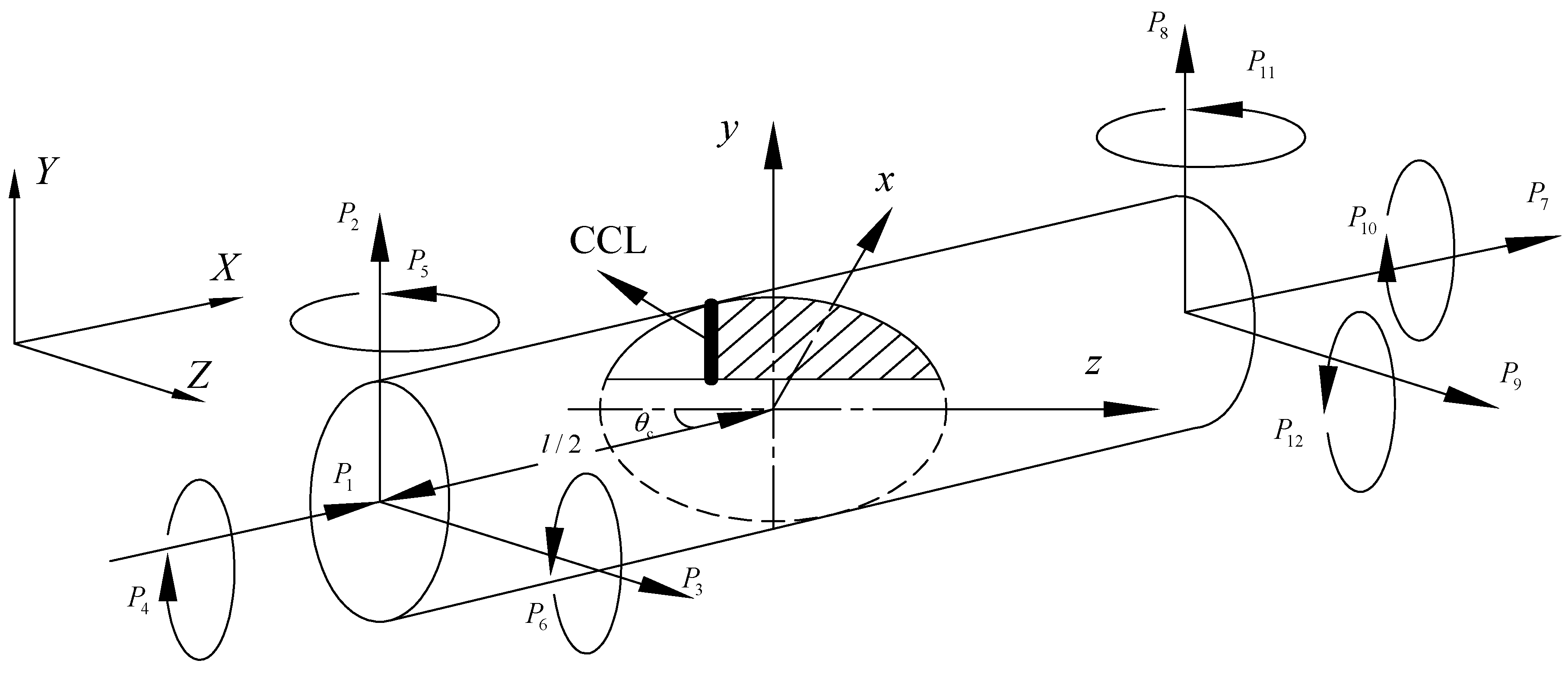
2.1. Crack Stiffness Matrix Calculation

A typical crack shaft element is described in Figure 1 X Y Z  and  x y z  are the global and local coordinate system, respectively. The crack element is considered with two nodes, and each node has three translational and three rotational degrees of freedom. The general forces applied in the crack element are denoted as P1P12. The length and radius of the crack element is l and R, respectively. The crack angle is shown as  θ c , the distance between the crack center and the end of shaft element equals to l/2 in this work.
u i  is denoted as the displacement along the direction of force Pi. According to Castigliano’s theorem and the Paris equation, the flexibility coefficients of crack element can be expressed as
g i j = u i P j = 2 P i P j ( U 0 + U c ) = 2 U 0 P i P j + 2 U c P i P j = g i j 0 + g i j c
where  g i j 0  are the flexibility coefficients of the un-cracked element, and  g i j c  the additional flexibility coefficients of the cracked element. The strain energy of un-cracked element  U 0  and the additional strain energy  U c  due to crack can be expressed according to strain energy release rate [4],
U 0 = 1 2 [ P 1 2 E A + α s P 2 2 G A + α s P 3 2 G A + P 4 2 E I p + ( P 3 x + P 5 ) 2 E I y + ( P 6 P 2 x ) 2 E I z ] d x
U c = 1 v 2 E A c [ ( i = 1 6 K I i ) 2 + ( i = 1 6 K II i ) 2 + ( 1 + v ) ( i = 1 6 K III i ) 2 ] d A c
where E and G are the Young’s modulus and the shear modulus; Ip is the polar moment of inertia; Iy and Iz are the area moment of inertia about axis y and z;  α s  is the shear coefficient; v is the Poisson’s ratio;  K I i , K II i  and  K III i  are the opening, sliding and tearing type stress intensity factors (SIFs), respectively; A is the area of the element cross-section; Ac is the crack section whose variation with time can describe the crack breathing phenomenon. From Equations (1)–(3), the flexibility coefficients matrix  G  of the cracked element (which is a symmetric matrix) can be expressed as
G = [ l E A + g 11 c g 12 c g 13 c g 14 c g 15 c g 16 c g 21 c α s l G A + l 3 3 E I z + g 22 c g 23 c g 24 c g 25 c l 2 4 E I z + g 26 c g 31 c g 32 c α s l G A + l 3 3 E I y + g 33 c g 34 c l 2 4 E I y + g 35 c g 36 c g 41 c g 42 c g 43 c l E I p + g 44 c g 45 c g 46 c g 51 c g 52 c l 2 4 E I y + g 53 c g 54 c l E I y + g 55 c g 56 c g 61 c l 2 4 E I z + g 62 c g 63 c g 64 c g 65 c l E I z + g 66 c ]
According to the static equilibrium of crack element,
{ P 1 + P 7 = 0 P 2 + P 8 = 0 P 3 + P 9 = 0 P 4 + P 10 = 0 P 5 + P 3 l + P 11 = 0 P 6 P 2 l + P 12 = 0 { P 1 , P 2 , , P 12 } T = T { P 1 , P 2 , , P 6 } T
where T corresponds to the transformation matrix,
T T = [ 1 0 0 0 0 0 1 0 0 0 0 0 0 1 0 0 0 0 0 1 0 0 0 l 0 0 1 0 0 0 0 0 1 0 l 0 0 0 0 1 0 0 0 0 0 1 0 0 0 0 0 0 1 0 0 0 0 0 1 0 0 0 0 0 0 0 0 0 0 0 0 1 ]
According to the Hooke’s law,
G { P 1 , P 2 , , P 6 } T = T T { u 1 , u 2 , , u 12 } T
Hence,
{ P 1 , P 2 , , P 12 } T = T G 1 T T { u 1 , u 2 , , u 12 } T
Then, crack stiffness matrix of a crack element can be derived as
K c e = T G 1 T T

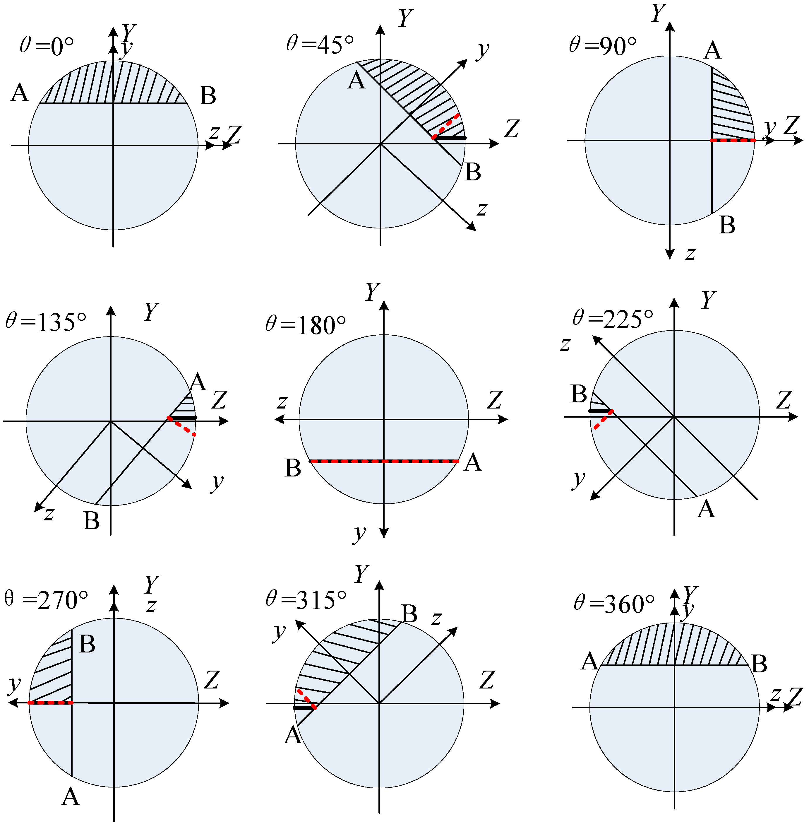
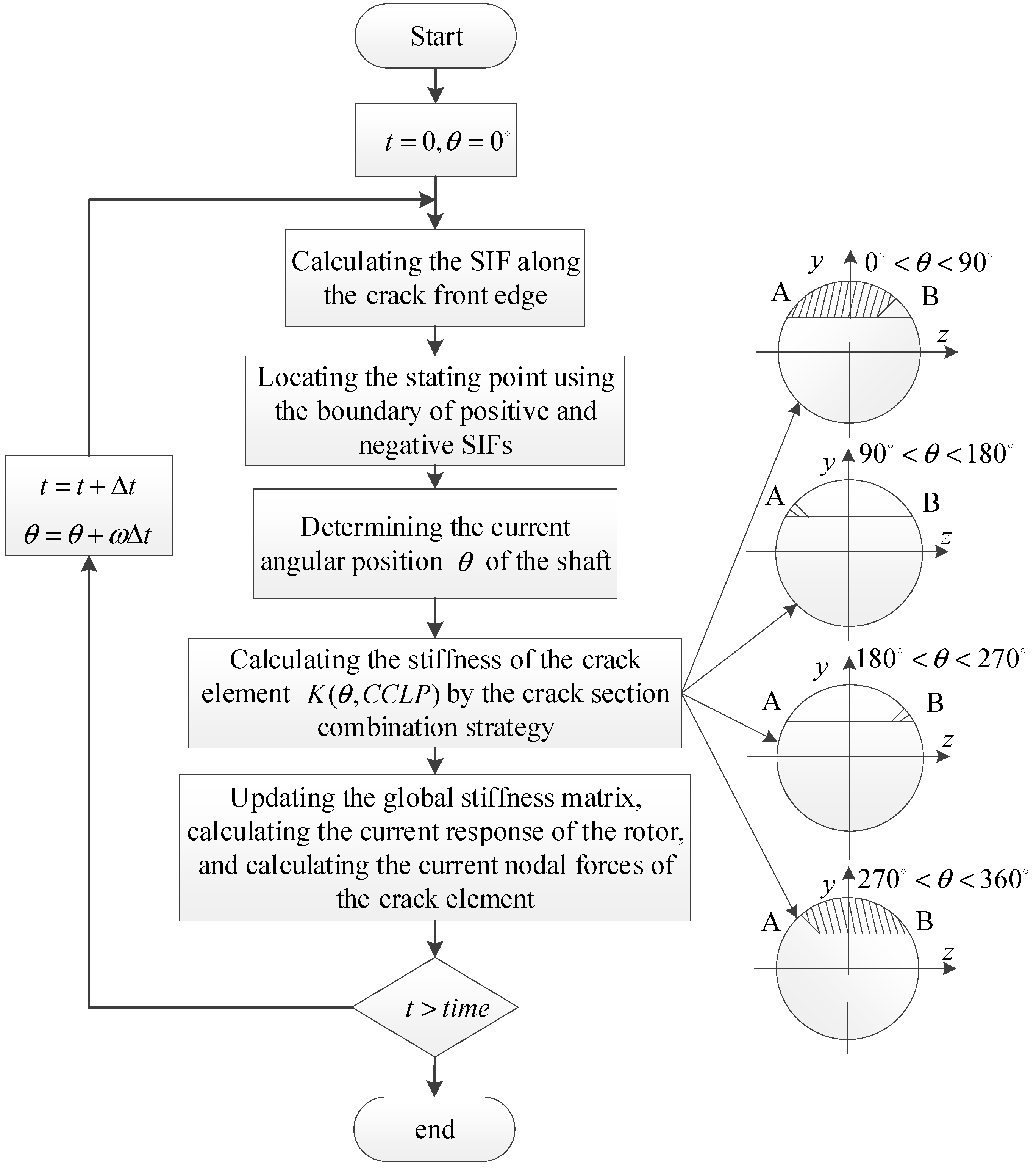
2.2. Improved Breathing Crack Model

From Equation (9), one can obtain the crack element matrix under a fixed open state. However, the crack is breathing with the operating of the rotor, which will lead to the crack section Ac in Equation (3) changing with time. Therefore, the issue of how to accurately describe the changing rule of crack opening and closing, e.g., the crack breathing model, is vitally important for dynamic modelling of a breathing crack rotor. The crack closure line position (CCLP) crack model [14] is one reliable crack breathing model. However, the assumption in the original model that the crack closure line is perpendicular to the crack front has a certain difference from the fact that the angle between the crack closure line and the crack edge is constantly changing. In order to simulate the breathing behavior of cracks more truly and accurately, the original CCLP crack breathing model is improved. It is assumed that the crack closing line and the crack edge have a certain angle, and that the angle is consistent with the current angular position of the shaft. Meanwhile, the starting point of the crack closing line is located by the boundary position of the positive and negative opening mode stress intensity factor  K I  at the crack front edge. The  K I  is the sum of opening mode stress intensity factor along the six directions of the six degrees of freedom expressed in Equation (10). When  K I  is positive, it means the position in the crack front is open, otherwise the position is closed.
K I = i = 1 6 K I i
The evolution process of the transverse crack breathing is depicted in Figure 2 (assuming that the external loads cause the shaft to bend downward in the X–Y plane, without losing generality). In Figure 2, YOZ and yOz are the global and rotation coordinates of the crack section, respectively, and θ is the angular position of the rotor, which is assumed to be 0 at the initial time. AB is the crack front line. The hatched region corresponds to the crack closure region; The crack closure lines determined by the improved CCLP (ICCLP) and the original CCLP breathing models are represented by solid and dotted lines, respectively. It should be noted that the evolution process of the crack breathing is similar to the neutral axis breathing model in [43]. However, the proposed breathing model takes the status of crack tips into consideration using the stress intensity factor, which will be more accurate.
Once the crack closure line is ascertained, the corresponding crack region Ac can be determined. By using the superposition of the flexibility and dividing the crack region reasonably, the crack flexibility matrix can be easily solved, and the corresponding stiffness matrix can then be obtained. The crack section is divided as shown in Figure 3 with three regions, S1, S2 and S3. Additionally, the crack calculation region Ac can be obtained using the combination strategy described in Equation (11).
A c = { 0   θ = 0 , θ = 360 S / 2   θ = 90 , θ = 270 S     θ = 180 S 1 + S 2     θ ( 0 , 90 ) ( 270 , 360 ) S ( S 1 + S 2 )   θ ( 90 , 180 ) ( 180 , 270 )
where  S = S 1 + S 2 + S 3 .
The calculation process is shown in Figure 4. For the initial state, the static deformation of the rotor without cracks is used to calculate the node force of the crack element.

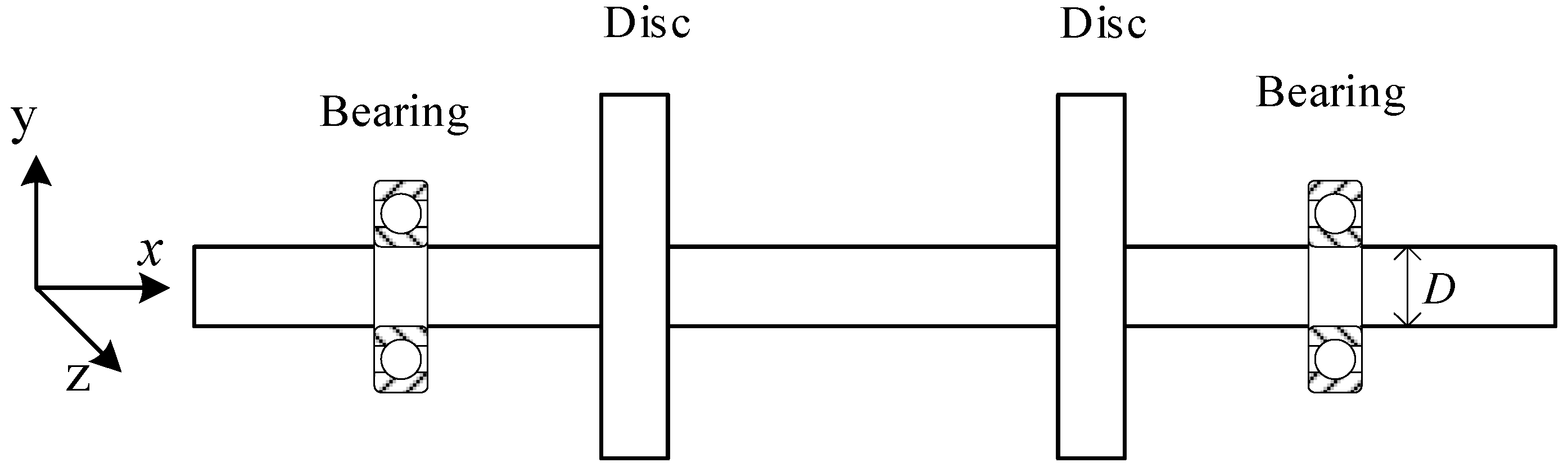
2.3. Finite Element Model of the Cracked Rotor–Bearing System

The finite element method was adopted to establish the cracked rotor–bearing system. The main idea was to assemble the crack element into the intact rotor–bearing system. The crack stiffness matrix and crack breathing model have been described above. The intact rotor–bearing system is shown in Figure 5, and has been established and experimental validated by the authors in [44]. The shaft is discretized into 60 two-node Timoshenko beam elements, and each node has three translational and three rotational degrees of freedom. The discs are assumed to be rigid and consider the gyroscopic effects, and the inertias are added to the corresponding node. A spring-damping model is used to simplify the bearing. The finite element model of the cracked rotor–bearing system can be derived by assembling all the element matrices as:
M q ¨ + ( C + Ω G y ) q ˙ + K ( q ) q = F e + F g + F ex
q = { q 1 , q 2 , q i , , q n } T
q i = { x i , y i , z i , θ x i , θ y i , θ z i } T
where  M C K G y  are the system mass matrix, Rayleigh damping matrix, stiffness matrix and gyroscopic matrix;  q  and  q i  are the total displacement vector and displacement vector of node i F e F g F ex  are the eccentric excitation vector, gravitational force vector and external excitation vector. Ω is the rotating frequency.

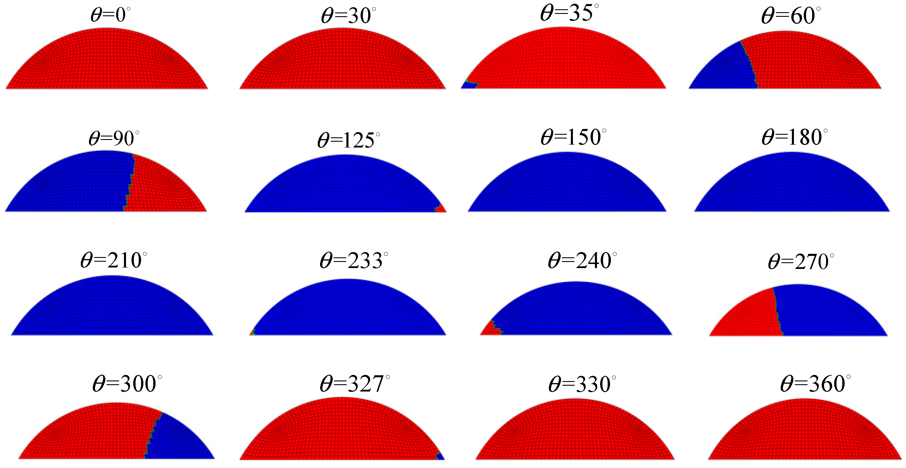
2.4. Model Validation

We consider the rotor system as shown in Figure 5 with a transverse crack located at the 30th element and with a depth of 0.25D. Figure 6 and Figure 7 are the crack stiffness obtained by the improved CCLP model and the original CCLP model during a one-circle rotation of the shaft.
From Figure 6 to Figure 7, it can be seen that the stiffness variation rules of the crack element obtained by ICCLP and CCLP are generally consistent, and the overall breathing behaviors are almost the same, except for stiffness differences in the partially open and closed state. Therefore, the correctness of the proposed ICCLP crack breathing model can be demonstrated. The main advantage of the ICCLP model is that its description of the crack closure line is more accurate and reasonable. In order to further verify the rationality of the improved model, the finite element model of the cracked rotor was established using the currently recognized three-dimensional non-linear contact crack model in ABAQUS, as shown in Figure 8. In the model, the C3D8R (in ABAQUS nomenclature) element is used to mesh the rotor. The crack is simulated considering two shafts jointed by means of the interaction ‘Tie’ (in ABAQUS nomenclature) between the surfaces that constitute the intact part of the cracked section. To avoid interpenetration between the crack faces when the crack is closed, a surface-to-surface contact interaction has been defined for the cracked part of the section. The normal behavior of interaction property is selected as ‘hard contact’ (in ABAQUS nomenclature), which does not allow penetration between the crack faces and prevents the transfer of tensile stress across the interface, and the tangential behavior is set as ‘rough friction’ (in ABAQUS nomenclature), which has an infinite coefficient of friction, avoiding all relative sliding motion between two contacting surfaces. The crack breathing state evolution within one cycle of rotor rotation is shown in Figure 9.
By comparing the variation rules of vertical bending stiffness K22 determined by CCLP model and ICCLP model in Figure 6 and the breathing states from ABAQUS in Figure 9, several key breathing states are shown in Table 1. It can be seen that the maximum error of the crack opening and closing rule determined by the ICCLP model and three-dimensional contact model is less than 5° which is smaller than the maximum error between the original CCLP model and three-dimensional contact model, and considering that the results determined by three-dimensional contact model can be further refined, the final error will be smaller. In addition, the ABAQUS simulation results show that there is a certain angle between the crack closure line and the crack front edge, which also proves the rationality of the hypothesis of the crack closure line in the proposed ICCLP model.
Through the above comparative study, the accuracy of the proposed ICCLP model is fully verified. In order to further analyze its influence on the response of the rotor system, the lateral vibration response of the cracked rotor under the ICCLP and CCLP models was compared as shown in Figure 10.
From Figure 10, one can see that the responses obtained by the two breathing models are similar in the time domain, but more local fluctuations appear in the responses from the ICCLP breathing model, which corresponds more high frequency components. From the frequency spectrum, the phenomenon is more obvious that there are more high order super-harmonic frequencies in the spectrum of the responses from the ICCLP model, which means that the ICCLP mode can capture the super-harmonic characteristics better than the CCLP model. These super-harmonic components are always important for crack diagnosis, and the ICCLP model can simulate the crack breathing more accurately.
Based on the established model, the super-harmonic components with different crack positions and crack depths at 1/3 and 1/2 critical speeds were extracted, and the 1×, 2×, 3× components are shown in Figure 11, where × corresponds to the rotating frequency and the relative amplitude is the ratio of the response between cracked rotors and un-cracked rotors.
From Figure 11, one can see the 1× and 2× components with different crack positions and depths at 1/3 and 1/2 critical speeds are gradually varied, while no obvious changing rules can be found for 3× components at either speed. What is more, there are sudden changes in 3× components with the variation of crack depth in Figure 11c,f, which are generated by the nonlinearity induced by crack breathing. Therefore, it is better to choose 1× and 2× components for crack identification than 3× components. Hence, in the following, the crack identification will be investigated using the 1× and 2× components with the designed artificial neural network.

3. Crack Identification Based on Artificial Neural Network

An artificial neural network is a kind of widely used artificial intelligence methodology which can provide a nonlinear mapping between inputs and outputs. A three-layer network can approximate any smooth mapping [45], so a three-layer backward propagation (BP) neural network was created to identify the crack, Figure 12 presents its structure, where  X = { x 1 , x 2 , , x n } T  is the input vector,  Y = { y 1 , y 2 , , y m } T  is the output vector,  ω i j  is the connecting weights of the ith input neuron to the jth hidden neuron, and  ω j k  is the connecting weights of the jth hidden neuron to the kth output neuron.
The relationship between inputs and outputs of the network can be expressed as
y k = f output { j = 1 l [ f hidden ( i = 1 n ω i j x i a j ) ] ω j k b k } k = 1 , 2 , , m ; j = 1 , 2 , , l ; i = 1 , 2 , , n f output ( x ) = f input ( x ) = 1 1 + e x
where k, l and m are the numbers of output neurons, hidden neurons and input neurons, respectively;  f output  and  f hidden  are the activation functions of output layer and hidden layer separately; and  a j  and  b k  correspond to the thresholds of the neurons of hidden layer and output layer.

3.1. Samples Generating and Network Training

It is well known that suitable samples are critically important for pattern identification using artificial neural networks. The nonlinearity of the crack is more obvious at the rotating speed around the 1/2 critical speed and the 1/3 critical speed, and from Figure 11 above, the 1× and 2× components are good features for crack identification; hence, the 1× and 2× components at the two speeds were selected to generate the samples for training and testing.
Considering the spatial information needed for crack position identification, it is not possible to realize the identification of crack position and depth simultaneously by only utilizing the features in one measurement point, which would lead to the multi-solution problem. Therefore, taking into consideration the convenience of measurement and the fewest measurement points demanded, the features from two measurement points are combined as inputs for the neural network. The measurement points can be installed relatively conveniently near the bearings in application.
Specifically, the crack position varies from element 10 to element 52 with a step of 2 elements, and the crack depth is from 0 to 0.45D with a step of 0.05D. Hence, there are 22 crack positions and 10 crack depths, and 220 samples in total. The inputs include the 1× and 2× super-harmonic components from the vertical rotor response obtained by two measurement points at 1/3 and 1/2 critical speed. So, each input feature vector has the dimension of 8, which is the number of neurons in the input layer of the BP network. Additionally, two output neurons corresponding to crack location and crack depth are set in the output layer. Among the 220 samples generated at 1/3 and 1/2 of the critical speed for different crack locations and depths, 180 samples were chosen randomly as training samples, and the rest used for the network validation and testing with default proportion in MATLAB.
The parameters of the BP network were obtained through a trial-and-error process, and the final parameter values used in the Levenberg–Marquardt back-propagation algorithm are as follows: 8 input layer neurons, 15 hidden layer neurons, 2 output layer neurons, learning ratio of 0.01, training goal of 0.00001, and 5000 epochs. Additionally, the training processes is shown as Figure 13.
From the training process, one can see that the speed of convergence is fast using the selected inputs and outputs, and the accuracy of training, validation and testing are all over 99%, which demonstrates the high training quality of the designed network. Additionally, the trained network can be used for crack identification.

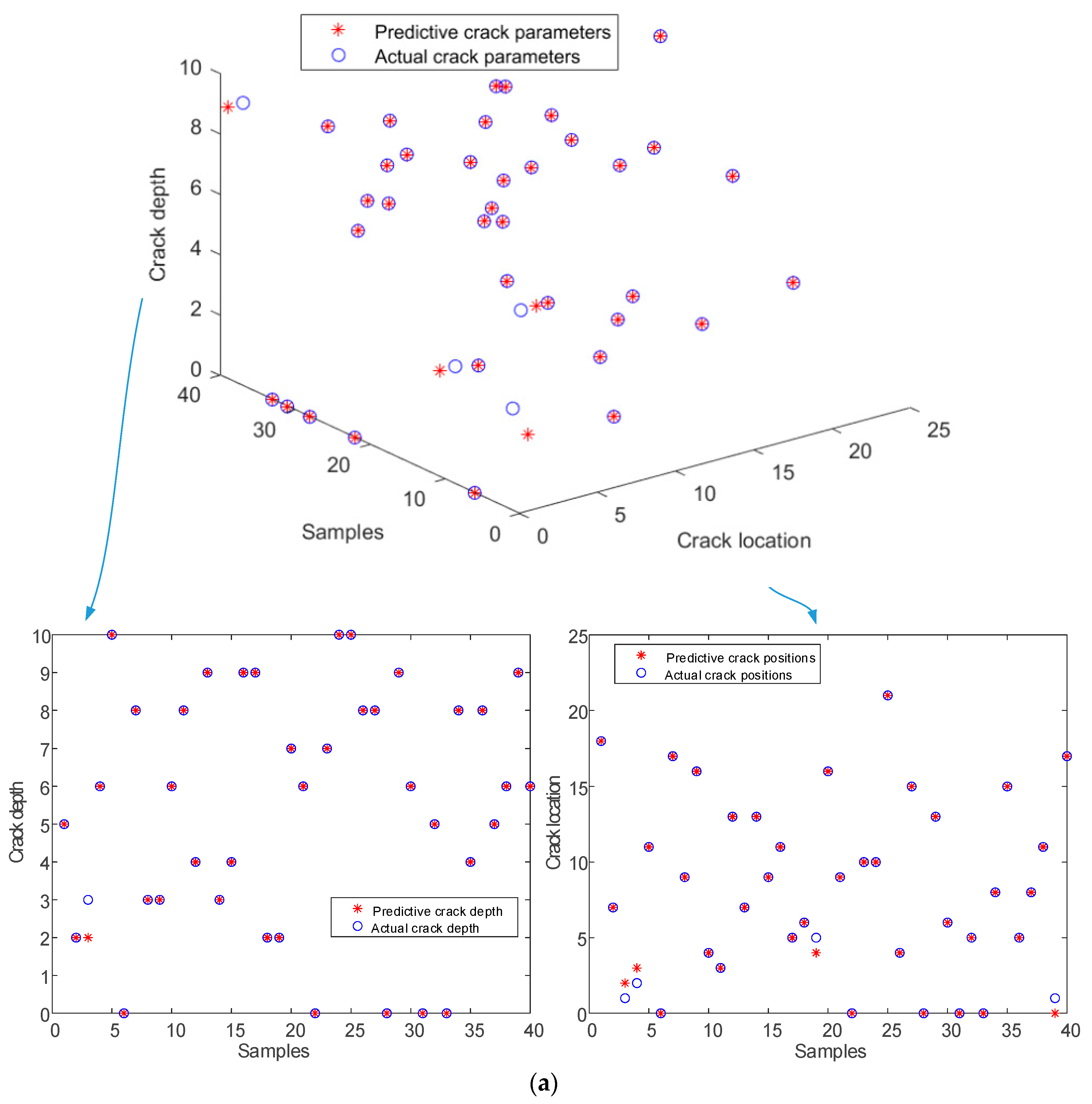
3.2. Crack Identification Results

The remaining 40 samples were used for crack identification, and in order to evaluate the robustness of the network, different level of noise were added to the testing samples, which means the samples for network training were free of noise, while the samples for crack identification featured different levels of noise. Figure 14 presents the identification results based on the trained network under different noise levels. As can be seen from Figure 14, the identified crack locations and depths both match well with the actual crack parameters, even for shallow cracks, especially when there is no noise.
In order to quantify the effectiveness of the method, some evaluation indexes were used which are defined as follows: detectable probability, which is defined as the ratio of identified cracked samples to all cracked samples, and represents the possibility that cracked samples will not be mistaken as un-cracked ones; false-alarm probability, which is defined as the ratio of un-cracked samples mistaken as cracked ones among all the un-cracked samples; identified location probability, which is the ratio of correctly identified crack locations which have the errors no more than 1 (as the location is the position of element in this work) among all the samples; identified depth probability, which is the ratio of correctly identified crack depths which have errors no greater than 0.5 (as the output of depth is an integer, the resolution is one) among all the samples whose locations are identified correctly.
The identification results calculated by the above evaluation indexes are shown in Table 2. It can be seen that the identification results are pretty good when there is no noise; with the increase in the noise level, the identification results gradually degrade to a limited degree, especially the crack location identification accuracy. While the identified depth probability is robust, which represents the likelihood that the crack location is accurately identified, the probability that the crack depth is also accurately identified is also robust to noise. In addition, the false-alarm probability and the detectable probability are not affected, which is a good indicator for application performance. Therefore, one can conclude that crack identification based on the BP network is efficient for the crack locations and depths, especially when the signal-noise ratio is enhanced by pre-processing methods.

4. Conclusions

An improved crack breathing model and its application in crack identification using super-harmonic features for rotors based on an artificial neural network (ANN) were studied in this work. The main conclusions are the following.
(1)
A cracked rotor with a response-dependent nonlinear breathing crack was modelled using the finite element method, and the original CCLP crack breathing model was improved by implementing a more reasonable crack closure line. The improved breathing model was validated by comparison with the original CCLP model and the 3D contact model. The dynamic responses were also compared, and the results indicate that the improved model is accurate and can reflect the super-harmonic nonlinear behavior of cracks better. The advantages of the improved crack model can be summarized as follows: (i) The improved crack model can consider the effect of stress intensity factor at the crack front, which makes the crack stiffness calculation more accurate. (ii) It can describe cracks with any crack angle under arbitrary excitations. (iii) It can describe the crack closure line more accurately and reasonably with affordable computation burden.
(2)
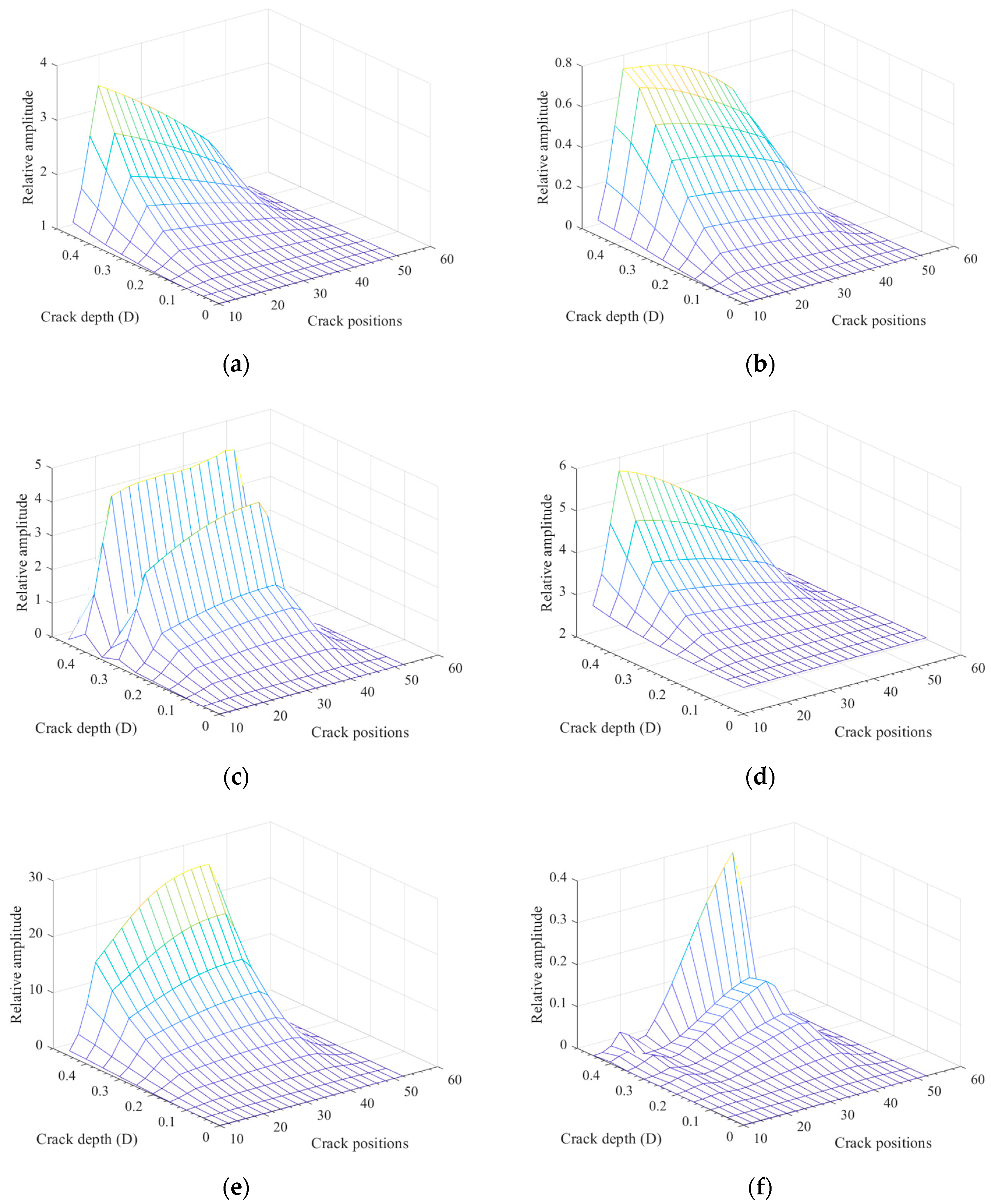
Variation rules of super-harmonic features with different crack positions and crack depths at 1/3 and 1/2 critical speed were investigated. The results show that 1× and 2× components are good indicators to distinguish different crack parameters.
(3)
A backward propagation (BP) artificial neural network was established using the features of 1× and 2× super-harmonic components at 1/3 and 1/2 critical speeds from two measurement points as inputs, and the corresponding crack locations and depths as outputs. The identification results show that the established network is efficient for crack position and depth identification, and, with the increase in the noise level, the identification accuracy remains higher than 90% but degrades to some degree. What is more, the detectable probability and false-alarm probability are robust to noise, which shows good performance for engineering applications.
This work mainly focuses on the feasibility of crack parameter identification using the artificial neural network method; because of the difficulty in breathing crack manufacturing with a control depth, experiments have not yet been carried out, which will be performed to evaluate the performance of the method in near future.

Author Contributions

Conceptualization, Q.L. and Z.L.; funding acquisition, Z.L.; investigation, Q.L. and S.C.; methodology, Q.L. and S.C.; supervision, Z.L.; validation, Q.L. and S.C.; writing—original draft, Q.L.; writing—review and editing, S.C. and Z.L. All authors have read and agreed to the published version of the manuscript.

Funding

This research was funded by the National Natural Science Foundation of China (51905388, 12102346). And The APC was funded by the National Natural Science Foundation of China (51905388, 12102346).

Data Availability Statement

Data will be available once asked by the readers.

Conflicts of Interest

The authors declare that there are no conflict of interest regarding the publication of this paper.

References

  1. Bovsunovsky, A.; Surace, C. Non-linearities in the vibrations of elastic structures with a closing crack: A state of the art review. Mech. Syst. Signal Process. 2015, 62, 129–148. [Google Scholar] [CrossRef]
  2. Kushwaha, N.; Patel, V.N. Modelling and analysis of a cracked rotor: A review of the literature and its implications. Arch. Appl. Mech. 2020, 90, 1215–1245. [Google Scholar] [CrossRef]
  3. Kumar, C.; Rastogi, V. A Brief Review on Dynamics of a Cracked Rotor. Int. J. Rotating Mach. 2009, 2009, 758108. [Google Scholar] [CrossRef]
  4. Papadopoulos, C.A. The strain energy release approach for modeling cracks in rotors: A state of the art review. Mech. Syst. Signal Process. 2008, 22, 763–789. [Google Scholar] [CrossRef]
  5. Sabnavis, G.; Kirk, R.G.; Kasarda, M.; Quinn, D. Cracked shaft detection and diagnostics: A literature review. Shock. Vib. Dig. 2004, 36, 287. [Google Scholar] [CrossRef]
  6. Friswell, M.I.; Penny, J.E. Crack modeling for structural health monitoring. Struct. Health Monit. 2002, 1, 139–148. [Google Scholar] [CrossRef]
  7. Jun, O.S.; Eun, H.J.; Earmme, Y.Y.; Lee, C.W. Modelling and vibration analysis of a simple rotor with a breathing crack. J. Sound Vib. 1992, 155, 273–290. [Google Scholar] [CrossRef]
  8. Al-Shudeifat, M.A. Impact of non-synchronous whirl on post-resonance backward whirl in vertical cracked rotors. J. Sound Vib. 2021, 520, 116605. [Google Scholar] [CrossRef]
  9. Han, Q.; Zhao, J.; Lu, W.; Peng, Z.; Chu, F. Steady-state response of a geared rotor system with slant cracked shaft and time-varying mesh stiffness. Commun. Nonlinear Sci. Numer. Simul. 2014, 19, 1156–1174. [Google Scholar] [CrossRef]
  10. Giannopoulos, G.I.; Georgantzinos, S.K.; Anifantis, N.K. Coupled vibration response of a shaft with a breathing crack. J. Sound Vib. 2015, 336, 191–206. [Google Scholar] [CrossRef]
  11. El Arem, S. On the mechanics of beams and shafts with cracks: A standard and generic approach. Eur. J. Mech. A/Solids 2020, 85, 104088. [Google Scholar] [CrossRef]
  12. Kulesza, Z.; Sawicki, J.T. Rigid finite element model of a cracked rotor. J. Sound Vib. 2012, 331, 4145–4169. [Google Scholar] [CrossRef]
  13. Wand, D.; Cao, H.; Yang, Y.; Du, M. Dynamic modelling and vibration analysis of cracked rotor-bearing system based on rigid body element method. Mech. Syst. Signal Process. 2023, 191, 110152. [Google Scholar]
  14. Darpe, A.K. Coupled vibrations of a rotor with slant crack. J. Sound Vib. 2007, 305, 172–193. [Google Scholar] [CrossRef]
  15. Guo, C.; Yan, J.; Yang, W. Crack detection for a Jeffcott rotor with a transverse crack: An experimental investigation. Mech. Syst. Signal Process. 2017, 83, 260–271. [Google Scholar] [CrossRef]
  16. Ganguly, K.; Roy, H. A novel geometric model of breathing crack and its influence on rotor dynamics. J. Vib. Control 2021, 28, 1802379016. [Google Scholar] [CrossRef]
  17. Kushwaha, N.; Patel, V.N. Nonlinear dynamic analysis of two-disk rotor system containing an unbalance influenced transverse crack. Nonlinear Dyn. 2023, 111, 1109–1137. [Google Scholar] [CrossRef]
  18. Yan, D.; Chen, Q.; Zheng, Y.; Liu, W. Parameter sensitivity and dynamic characteristic analysis of bulb hydro generating unit with shaft crack fault. Mech. Syst. Signal Process. 2021, 158, 107732. [Google Scholar] [CrossRef]
  19. Muñoz-Abella, B.; Montero, L.; Rubio, P.; Rubio, L. Determination of the Critical Speed of a Cracked Shaft from Experimental Data. Sensors 2022, 22, 9777. [Google Scholar] [CrossRef]
  20. Zhang, B.; Li, Y. Six degrees of freedom coupled dynamic response of rotor with a transverse breathing crack. Nonlinear Dyn. 2014, 78, 1843–1861. [Google Scholar] [CrossRef]
  21. Darpe, A.K.; Gupta, K.; Chawla, A. Coupled bending, longitudinal and torsional vibrations of a cracked rotor. J. Sound Vib. 2004, 269, 33–60. [Google Scholar] [CrossRef]
  22. Patel, T.H.; Darpe, A.K. Influence of crack breathing model on nonlinear dynamics of a cracked rotor. J. Sound Vib. 2008, 311, 953–972. [Google Scholar] [CrossRef]
  23. Bachschmid, N.; Pennacchi, P.; Tanzi, E. Some remarks on breathing mechanism, on non-linear effects and on slant and helicoidal cracks. Mech. Syst. Signal Process. 2008, 22, 879–904. [Google Scholar] [CrossRef]
  24. Soeffker, D.; Wei, C.; Wolff, S.; Saadawia, M.S. Detection of rotor cracks: Comparison of an old model-based approach with a new signal-based approach. Nonlinear Dyn. 2016, 83, 1153–1170. [Google Scholar] [CrossRef]
  25. Rathna Prasad, S.; Sekhar, A.S. Detection and localization of fatigue-induced transverse crack in a rotor shaft using principal component analysis. Struct. Health Monit. 2020, 20, 84066386. [Google Scholar] [CrossRef]
  26. Xiang, L.; Zhang, Y.; Hu, A.; Ye, F. Dynamic analysis and experiment investigation of a cracked dual-disc bearing-rotor system based on orbit morphological characteristics. Appl. Math. Model. 2020, 80, 17–32. [Google Scholar] [CrossRef]
  27. Dong, H.B.; Chen, X.F.; Li, B.; Qi, K.Y.; He, Z.J. Rotor crack detection based on high-precision modal parameter identification method and wavelet finite element model. Mech. Syst. Signal Process. 2009, 23, 869–883. [Google Scholar] [CrossRef]
  28. Zapico-Valle, J.L.; Rodríguez, E.; García-Diéguez, M.; Cortizo, J.L. Rotor crack identification based on neural networks and modal data. Meccanica 2014, 49, 305–324. [Google Scholar] [CrossRef]
  29. Sathujoda, P. Detection of a slant crack in a rotor bearing system during shut-down. Mech. Based Des. Struct. Mach. 2020, 48, 266–276. [Google Scholar] [CrossRef]
  30. Lin, Y.; Chu, F. The dynamic behavior of a rotor system with a slant crack on the shaft. Mech. Syst. Signal Process. 2010, 24, 522–545. [Google Scholar] [CrossRef]
  31. Spiros Pantelakis, P.; Chasalevris, A.C.; Papadopoulos, C.A. Experimental detection of an early developed crack in rotor-bearing systems using an AMB. Int. J. Struct. Integr. 2015, 6, 194–213. [Google Scholar] [CrossRef]
  32. Kulesza, Z. Dynamic behavior of cracked rotor subjected to multisine excitation. J. Sound Vib. 2014, 333, 1369–1378. [Google Scholar] [CrossRef]
  33. Cavalini, A.A., Jr.; Sanches, L.; Bachschmid, N.; Steffen Jr, V. Crack identification for rotating machines based on a nonlinear approach. Mech. Syst. Signal Process. 2016, 79, 72–85. [Google Scholar] [CrossRef]
  34. Chandra, N.H.; Sekhar, A.S. Fault detection in rotor bearing systems using time frequency techniques. Mech. Syst. Signal Process. 2016, 72, 105–133. [Google Scholar] [CrossRef]
  35. Sampaio, D.L.; Nicoletti, R. Detection of cracks in shafts with the Approximated Entropy algorithm. Mech. Syst. Signal Process. 2016, 72, 286–302. [Google Scholar] [CrossRef]
  36. Sinou, J. Detection of cracks in rotor based on the 2× and 3× super-harmonic frequency components and the crack–unbalance interactions. Commun. Nonlinear Sci. Numer. Simul. 2008, 13, 2024–2040. [Google Scholar] [CrossRef]
  37. Gómez, M.J.; Castejón, C.; Corral, E.; García-Prada, J.C. Analysis of the influence of crack location for diagnosis in rotating shafts based on 3 x energy. Mech. Mach. Theory 2016, 103, 167–173. [Google Scholar] [CrossRef]
  38. Guo, C.; Al-Shudeifat, M.A.; Yan, J.; Bergman, L.A.; McFarland, D.M.; Butcher, E.A. Application of empirical mode decomposition to a Jeffcott rotor with a breathing crack. J. Sound Vib. 2013, 332, 3881. [Google Scholar] [CrossRef]
  39. Wang, C.; Zheng, Z.; Guo, D.; Liu, T.; Xie, Y.; Zhang, D. An Experimental Setup to Detect the Crack Fault of Asymmetric Rotors Based on a Deep Learning Method. Appl. Sci. 2023, 13, 1327. [Google Scholar] [CrossRef]
  40. Jin, Y.; Hou, L.; Chen, Y.; Lu, Z. An effective crack position diagnosis method for the hollow shaft rotor system based on the convolutional neural network and deep metric learning. Chin. J. Aeronaut. 2021, 35, 242–254. [Google Scholar] [CrossRef]
  41. Guo, T.; Wu, L.; Wang, C.; Xu, Z. Damage detection in a novel deep-learning framework: A robust method for feature extraction. Struct. Health Monit. 2020, 19, 424–442. [Google Scholar] [CrossRef]
  42. Babu Rao, K.; Mallikarjuna Reddy, D. Fault detection in rotor system by discrete wavelet neural network algorithm. J. Vib. Control 2021, 28, 1802379037. [Google Scholar] [CrossRef]
  43. Guo, C.Z.; Yan, J.H.; Bergman, L.A. Experimental Dynamic Analysis of a Breathing Cracked Rotor. Chin. J. Mech. Eng. 2017, 30, 1177–1183. [Google Scholar] [CrossRef]
  44. Lu, Z.; Lv, Y.; Ouyang, H. A Super-Harmonic Feature Based Updating Method for Crack Identification in Rotors Using a Kriging Surrogate Model. Appl. Sci. 2019, 9, 2428. [Google Scholar] [CrossRef]
  45. Mohammed, A.A.; Neilson, R.D.; Deans, W.F.; MacConnell, P. Crack detection in a rotating shaft using artificial neural networks and PSD characterisation. Meccanica 2014, 49, 255–266. [Google Scholar] [CrossRef]
Figure 1. Schematic diagram of crack element with general forces.
Machines 11 00569 g001
Figure 2. Evolution process of crack breathing in one cycle of the rotor rotation.
Machines 11 00569 g002
Figure 3. Schematic diagram of crack stiffness calculation sections based on the ICCLP breathing model.
Machines 11 00569 g003
Figure 4. Flowchart for ICCLP-based crack element stiffness calculation.
Machines 11 00569 g004
Figure 5. The intact rotor–bearing system for investigation.
Machines 11 00569 g005
Figure 6. Crack main stiffness obtained by the ICCLP breathing model and CCLP breathing model.
Machines 11 00569 g006
Figure 7. Crack coupled stiffness obtained by the ICCLP breathing model and CCLP breathing model.
Machines 11 00569 g007
Figure 8. Cracked rotor based on a 3D contact crack model.
Machines 11 00569 g008
Figure 9. Crack breathing evolution rule in one circle.
Machines 11 00569 g009
Figure 10. Horizontal response of rotor with 90° transverse crack.
Machines 11 00569 g010
Figure 11. Varying rules of super-harmonic features with crack positions and crack depths: (a) 1× components at 1/3 critical speed; (b) 2× components at 1/3 critical speed; (c) 3× components at 1/3 critical speed; (d) 1× components at 1/2 critical speed; (e) 2× components at 1/2 critical speed; (f) 3× components at 1/2 critical speed.
Machines 11 00569 g011
Figure 12. Structure of the BP neural network.
Machines 11 00569 g012
Figure 13. Training process of the designed network: (a) convergence plot; (b) regression plot.
Machines 11 00569 g013aMachines 11 00569 g013b
Figure 14. Comparison of identification results based on the trained network and actual results under different levels of noise: (a) no noise; (b) 5% noise; (c) 10% noise.
Machines 11 00569 g014aMachines 11 00569 g014bMachines 11 00569 g014c
Table 1. Breathing state comparison between the ICCLP model, CCLP model and 3D contact model.
State of Crack Open and Close ICCLP CCLPThree-Dimensional Contact Model
Start opening33°30°35°
Fully open130°140°125°
Start closing228°220°233°
Fully closed328°330°327°
Table 2. Identification results under different level of noise.
Evaluation IndexNo Noise5% Noise10% Noise
Detectable probability 100%100%100%
False-alarm probability0%0%0%
Identified location probability100%92.5%90%
Identified depth probability97.5%97.3%97.2%
Disclaimer/Publisher’s Note: The statements, opinions and data contained in all publications are solely those of the individual author(s) and contributor(s) and not of MDPI and/or the editor(s). MDPI and/or the editor(s) disclaim responsibility for any injury to people or property resulting from any ideas, methods, instructions or products referred to in the content.

