1. Introduction
The choice of vehicle should be based on a comparison of the efficiency of possible alternatives. Complex performance indicators are used to take into account as many factors as possible. Their structure may contain economic, technical, and environmental components [
1]. The technical component allows for the assessment of the degree of adaptability of the vehicle to given operating conditions. Within its limits, efficiency criteria are distinguished according to the absolute and specific energy consumption of the vehicle. In most countries, the ratio of actual fuel consumption to completed transport work is used to evaluate the efficiency of transport work [
2]. In references [
3,
4], the authors evaluate the mechanical efficiency of large-class city buses using the ratio of the useful work performed on the sections of a given route in the city of Rzeszów (Poland) to the energy consumption of the studied bus model. The relevant analytical dependencies, presented in [
2,
3,
4], take into account the speed, acceleration, and modes of movement of the vehicle, the gradient of the road, and the weather conditions, and require the determination of the total resistance of the road. In [
2], only the general methodology for evaluating the efficiency of the vehicle according to various indicators of fuel efficiency is described. In [
3,
4], the efficiency of the bus under the conditions of rectilinear movement is studied on a given segment. In these works, examples of the evaluation of the technical efficiency of vehicles moving along a curvilinear trajectory were not considered.
Usually, the driving route contains slopes and curved sections. Therefore, both the longitudinal and transverse dynamics of connected automated vehicles were taken into account in [
5]. The results of the computer simulation in [
5] show that the strategy of integrated planning of traffic modes based on the complex dynamics of the vehicle provided an acceleration of the vehicle by less than 2 m∙s
−2, and demonstrate the advantages of this strategy in terms of transverse stability and energy efficiency on continuous curved roads compared to the longitudinal strategy. The developed models took into account total road resistance and road topography; however, they were implemented only for vehicles of the same type with the same set of technical and operational characteristics. The authors of [
6] evaluate the energy efficiency of vehicles for given categories and types of power plants on city roads, for which the resistance of the road and the level of curvature of the road are determined. However, these parameters contain unclear information. The level of curvature of the road is described by a linguistic variable that can take the same value for different trajectories of movement within a given range of radii. The results of study [
7] revealed that the speed and transverse location of vehicles on the carriageway under the conditions of curved traffic depend on the place of interaction between vehicles in front of the center of the curve.
In references [
8,
9], the parameters of curvilinear movement of a tracked vehicle were investigated. Within the framework of study [
8], the position of the longitudinal axis and the angle of the deviation vector of the speed of movement were determined as the main parameters. Additionally, the turning resistance coefficient is taken into account, which is determined based on the length of the track, angular velocity, normal, and tangential acceleration of the vehicle body. The presence of significant noise in the acceleration values during measurement by inertial sensors significantly limits the accuracy of determining the kinematic and force parameters that characterize the change in the direction of movement of the car. The exponential dependence of the turning resistance coefficient is proposed, taking into account its maximum value and the ratio of the coefficient of curvature to the curvature, at which the force of lateral sliding of the lower rollers is equal to the force of friction. However, the resulting models describe the movement of tracked vehicles with the discrete properties of the steering system on dry sandy soil. Equations of the curvilinear trajectory of a four-wheeled tractor were obtained in [
9], simulating the tractor’s entry into a turn, the exit of a turn, and the rotation of its body. The deviation of the wheels of both axles under the action of lateral forces is taken into account. The correlation dependence between the radius of curvature and the turning angle of the machine frame is constructed. The obtained equations allow for the calculation of the coordinates of the center of mass of the vehicle depending on the turning angle and the intensity of the change in the course angle. The results of this study are the basis for the development of new methods to reduce fuel consumption and maintain the stability of vehicles under operating conditions. However, the obtained models do not take into account such factors as terrain, weather conditions, and the sliding and skidding of wheels during curvilinear movement.
The authors of [
10] investigated the influence of the design of inter-wheel differentials on the resistance to curvilinear movement on paved roads. The study was carried out on the example of an all-wheel drive car with a wheel formula of 8 × 8. As one of the criteria for the analysis of the resistance to curvilinear movement, the relative increase in the actual turning radius of the car, taking into account the slip of the tire at the point of contact compared with the theoretical turning radius calculated without taking into account the slip, was chosen. Among the three self-locking high-friction differentials considered, the models characterizing the operation of inter-wheel differentials, in which the degree of locking depends on the square of the difference in the angular velocities of the half-axles, turned out to be the most rational in terms of the degree of influence on the resistance to curvilinear movement. The authors did not take into account the peculiarities of the operating conditions of the vehicle and the parameters of stability during acceleration.
In [
11], the analytical dependence of the total coefficient of road resistance of special wheeled vehicles on vehicle acceleration, the angular velocity, the angular acceleration, and the distance between the sensors in the lateral plane are presented. The use of the model is limited by the given conditions. The obtained results made it possible to study the dynamics of the change in the coefficient of the road resistance depending on the speed of movement of the vehicles with a 6 × 6 wheel formula.
In [
12], the authors provide data according to which, among all resistance forces in a modern passenger car, 20–30% of the total fuel consumption is due to rolling resistance (depending on driving conditions and tire characteristics). The author claims that reducing its value by 10% will provide a reduction in fuel consumption from 1% to 2%. Taking into account the ranges of values of the rolling resistance coefficient, its accurate assessment will allow determining the optimal driving modes, reducing rolling resistance and harmful emissions into the atmosphere. Rolling resistance cannot be physically measured. Its value strongly depends on the speed of the vehicle, the type of road surface, tire pressure, and tire temperature.
Special attention was paid to the rolling resistance coefficient on an undeformed support surface in the work of Soltus A.P., Wong J.Y., Ilarionov V.A., Sakhno V.P., Petrushov V.A., Jazar R.N., Gillespie T., Suntsov N.V., Knoros V.I., Falkevych B.S. and others; special attention was paid to the determination of the rolling resistance coefficient on an undeformed support surface because, as shown by the results of statistical studies, wheeled vehicles move mainly along a trajectory close to a straight line, and the turning angles of the steered wheels are within 1.5° [
13].
To determine the coefficient
f when driving a car on roads with good quality asphalt or cement concrete, reference [
14] recommends an empirical dependence that takes into account only the speed of the car, and after equivalent transformations, takes the form:
where
V is the speed of the vehicle, m/s.
In [
15], it is recommended that this coefficient is determined by the expression:
where
V is the speed of the vehicle, m/s.
In reference [
16], it is stated that for traction calculations, it is sometimes sufficient to submit the coefficient of rolling resistance in the form of linear dependence on the speed of movement. According to [
16], for the most common range of air pressure in the tire (about 0.179 MPa) at speeds of up to 130 km/h, it is recommended that the average value of the rolling resistance coefficient is determined using the following expression:
where
V is the speed of the vehicle, m/s.
The analysis of Dependencies (1)–(3) shows that they are functions of the speed of movement of the first order; accordingly, these dependencies will be depicted in the form of straight lines on graphs. If we take speed V = 0 in these dependencies, then we will obtain the values of the rolling resistance coefficient at the low speeds of 0.0114, 0.0115 and 0.01, respectively. At the same time, the value of the coefficient f will also be influenced by the values of indicators 32, 31.94, and 44.44, into which the speed V is divided. Therefore, at a speed of movement V = 15 m/s, the rolling resistance coefficients, calculated according to Expressions (1)–(3), will acquire the following values: 0.0167, 0.0169, and 0.0134. The difference in calculations is 20.7%.
At the same time, Dependencies (1)–(3) were obtained experimentally for specific tires on an undistorted surface, so they cannot be used to determine the rolling resistance coefficient for other tires, and even more so on different support surfaces.
In contrast to the above dependencies, in reference [
17], to determine the coefficient
f, the authors recommend a dependency in which, in addition to the speed of movement, the experimentally obtained values of the rolling resistance coefficient at low speed of movement and they also recommend a coefficient that takes into account the air pressure, the type of tire, and its dimensions:
where
f0 is the rolling resistance coefficient of the tire at low speed, which is determined experimentally, taking into account the supporting surface and pressure in the tire;
kf is a coefficient, the value of which is recommended in [
17], to be determined experimentally for each type and size of tire depending on the internal pressure of the tire;
V is vehicle speed, km/h.
Paper [
17] gives experimental values of coefficient
f0 for cement–concrete, gravel or crushed stone pavement cobblestones in dry, wet, dirty, snowy, and icy conditions. So, for a dry asphalt concrete coating, the coefficient
f0 is within 0.012–0.025, for a dry crushed stone or gravel coating it is within 0.02–0.025, and for dry paving stones, 0.025–0.035. It can be determined from the analysis of the data presented in the work which types of tire the value of coefficient
f0 is given. The value of coefficient
kf is not given in this paper.
In references [
17,
18,
19], for the calculation of the rolling resistance coefficient
f at the nominal air pressure in the tire depending on the speed of movement, empirical second-order dependencies are recommended, taking into account the experimental values of this coefficient at low speed.
Thus, in reference [
14], the following dependence is given:
where
f0 is the rolling resistance coefficient of the tire at low speed, which is recommended that it is determined experimentally;
V is the speed of the car, m/s.
In references [
13,
17], the dependence is recommended for determining coefficient
f:
where
f0 is the rolling resistance coefficient of the tire at low speed;
V is the speed of the car, m/s.
At the same time, Dependencies (5) and (6) differ from each other only by coefficients 1/1500 and 1/2143. In this case, the difference in the calculations of coefficient f is based on these dependencies at the speed of movement V = 15 m/s is 3.9%.
According to references [
18,
19], the following dependence is recommended to determine the rolling resistance coefficient
f:
where
f0 is the rolling resistance at low speed;
kf is the speed influence coefficient, the value of which, in the absence of experimental data, is recommended to take
kf = 7·× 10
−6 s
2/m
2;
V is the speed of the vehicle, m/s.
In reference [
19], it is stated that during calculations according to Dependence (7), the coefficients
f0 and
kf should be determined experimentally for each individual tire. For most car tires, it is recommended that they take
f0 = 0.015,
kf = 7·× 10
−6 s
2/m
2.
In references [
20,
21,
22], dependences to determine the rolling resistance coefficient are given, in which the air pressure in the tire is additionally taken into account. For example, in references [
20,
21], the following dependence is given for passenger car tires on roads with a concrete surface:
where
V is the speed of the car; m/s;
f0,
fs are coefficients depending on the air pressure in the tire.
The coefficients
f0,
fs in references [
20,
21] are recommended to be determined according to the graphs shown in
Figure 1.
In reference [
22], an empirical dependence is given for the determination of the coefficient of rolling resistance
f on an asphalt concrete surface, which takes into account the speed of movement and the air pressure in the tire (9). At the same time, experimental studies of the coefficient of rolling resistance of a car wheel were carried out at a speed of 30–170 km/h and an air pressure of 100–500 kPa in the tire.
where
k0 and
c are coefficients depending on the air pressure in the tire, the values of which are given in
Table 1;
V is the speed of the vehicle, m/s.
If we take speed
V close to 0, then in Dependence (9), coefficient
k0 is the rolling resistance coefficient
f0, taking into account that
ecV ≈ 1. At the same time, reference [
22] does not indicate for which type of tire the value of coefficient
k0 is given.
Paper [
23] gives an empirical relationship between the force of rolling resistance, air pressure in the tire, and the speed of the car on a paved road.
where
Gw is the load, tnf;
Pf is the rolling resistance force, kgf;
pt is the air pressure in the tire, kgf/cm
2;
V is the speed of the vehicle, km/h.
From Dependence (10), after simple transformations, the following expression can be obtained to determine the rolling resistance coefficient
f, depending on the air pressure in the tire and the speed of movement in terms of SI units:
where
pt is the air pressure in the tire, MPa;
V is the speed of the vehicle, m/s.
The first component of Dependence (11) determines the coefficient of rolling resistance at a speed close to zero, and the second component determines the influence of speed on its value. This dependence makes it possible to determine the influence of the air pressure in tire pt on each component of coefficient f.
Analysis of references [
13,
17,
19] showed that lower values of the rolling resistance coefficient are typical of passenger car tires with a metal-cord cover, and higher values are typical of truck tires with adjustable air pressure. For specific tires, this coefficient is determined experimentally.
If we take into account that the coefficient of rolling resistance does not exceed 0.008 under the best conditions, then from the analysis of Dependence (11), it can be seen that it is valid under the condition that f = 0.0031/pt > 0.008. Under this condition, pt < 0.3872 MPa. It is obvious that Dependence (11) is typical of tires in which the air pressure does not exceed 0.3872 MPa.
In [
24], an empirical dependence in the form of a polynomial of the third degree is recommended for determining the rolling resistance coefficient on paved roads. If in this dependence we express the variables in terms of SI units, then we obtain the following expression:
where
pt is the air pressure in the tire, MPa;
V is the speed of the car, m/s.
Similar to the above, Dependence (12) is valid under the condition that . Under these conditions, the dependence is typical of tires with air pressure pt < 0.3655 MPa.
Therefore, Dependencies (11) and (12) are valid for determining the rolling resistance coefficient of tires in which the air pressure does not exceed 0.3872 MPa and 0.3655 MPa, respectively. Under other conditions, the obtained values of this coefficient are beyond the possible values obtained experimentally.
At the same time, the number of works dedicated to the study of the resistance of the wheel movement along a curved path is limited, which is explained, on the one hand, by the movement of vehicles on trajectories that are almost straight-line movements, and on the other hand, by the complexity of the phenomena associated with such movements. Therefore, the purpose of this paper is to study the regularities of changes in the motion resistance along a curvilinear trajectory using the example of typical models of two-axle vehicles.
The paper consists of four sections. In
Section 1, the results of the research of other scientists on the motion resistance along a curvilinear trajectory and the rolling resistance on a straight line as its component are analyzed. In
Section 2, the methodology for analytically determining the increase in the motion resistance along a curvilinear trajectory, taking into account the slip angle of the wheel, is presented.
Section 3 presents the results of determining the rolling resistance coefficient using different methods, including taking into account the air pressure in the tires, as well as the results of the experiment on determining the motion resistance coefficient along a curvilinear trajectory. An analytical dependence of the increase in the motion resistance was obtained for typical two-axle vehicles with different design structures and types of tires. The discussion and conclusions are presented in
Section 4.
2. Materials and Methods
The elastic wheel is considered to be a complete and complex mechanism that converts the rotational movement of the wheel relative to the axis of rotation into its translational movement on the support surface. It includes the hard disc, the elastic body of the tire (the tire) and the contact patch of the tire, which belong to both the wheel and the supporting surface. Its integrity is determined by external and internal connections. External connections form the integrity of its design, and the internal ones represent requirements for it, which in the future, will form the technical and economic indicators of the wheeled vehicle. At the same time, one of the main requirements for the wheel is the provision of minimal resistance to its movement, which directly determines the fuel economy of the vehicle [
25,
26].
When an elastic wheel moves in a straight line along an undeformed support surface, it is necessary to overcome the friction in the rubber–metal–fabric cover, the tread rubber, and the friction formed when the tire comes in contact with the support surface, which, during the movement of the wheel, causes a displacement of the uniform normal reactions relative to the center of the tire patch by the amount
d. This displacement of the uniform relative to the center of the contact patch causes the moment of rolling resistance of the elastic wheel. In the theory, displacement
d is taken into account by the coefficient of rolling resistance
f, which is understood as the ratio of displacement
d to the dynamic radius of wheel
rd, and it is determined by the expression:
To move the wheel, it is necessary to overcome this moment of resistance. If the wheel is driven, the pushing force is supplied from the frame of the vehicle to the axle of the wheel, and if the wheel is not driven, the torque is supplied directly to the disc from the transmission of the vehicle. The force and torque applied to the hard disc from the vehicle frame and transmission cause reactions when the tire comes in contact with the bearing surface, causing the vehicle to move [
25,
26].
Therefore, in order to ensure the rectilinear movement of an elastic wheel on an undeformed support surface, it is necessary to overcome the rolling resistance, which depends on the value of the rolling resistance coefficient f. Therefore, determining the rolling resistance of an elastic wheel along a straight path is reduced to the calculation of the coefficient of rolling resistance, which is one of the main characteristics of an elastic wheel, as it directly affects the technical and economic properties of the wheel. At the same time, we consider the rectilinear motion of an elastic wheel to be a special case of curvilinear motion when the radius of curvature of the wheel’s trajectory moves towards infinity.
In the future, when studying the resistance of the wheel movement along a curved trajectory, we will adopt the following:
The supporting surface is a road with an asphalt concrete surface;
Only adhesion zones are present in the contact patch;
When the wheel rolls in a circle, the wheel twists and moves sideways while traveling on a path equal to half the length of the longitudinal axis of the tire contact patch;
When moving in a circle, the energy supplied to the wheel is distributed equally between the turning and lateral displacement of the disc relative to the tire contact patch;
The relationship between the lateral force and the slip angle is linear.
During the wheel motion along a curved trajectory, the tire contact patch takes part in the transfer and relative motion [
25,
27]. The center of transfer motion is the center of the turning of the vehicle, which is formed by the angle of turning of the steered wheels and the base of the vehicle. As for the center of relative motion, it is located within the contact patch of the tire, and as the radius of curvature increases, it shifts to the edge of the patch [
25,
27]. According to reference [
25], when rolling an elastic wheel along a curved trajectory with a radius of curvature
R > 1 m, with sufficient accuracy for practice, it can be assumed that the center of the relative turning of the contact patch shifts to the edge of the patch. The trajectory of the curvilinear movement of the elastic wheel can be determined by the trajectory of the center of relative rotation of the contact patch. At the same time, during rectilinear movement, the trajectory is determined by the movement of the geometric center of the tire contact patch.
Analysis of the results of the conducted research [
25,
27] proved that when moving along a curved trajectory, in the absence of sliding in the contact of the wheel with the support surface, there is simultaneous turning and lateral displacement of the disc relative to the contact patch of the tire when the elastic wheel passes a distance equal to half the length of the longitudinal axis of the contact patch of the tire.
Given that the trajectory of the wheel movement will be determined by the center of the relative turning of the contact patch of the tire, the relative turning of the disc and its lateral displacement will be determined by the relative positions of the contact patch of the tire before and after the elastic wheel passes a distance equal to half the length of the longitudinal axis of the contact patch.
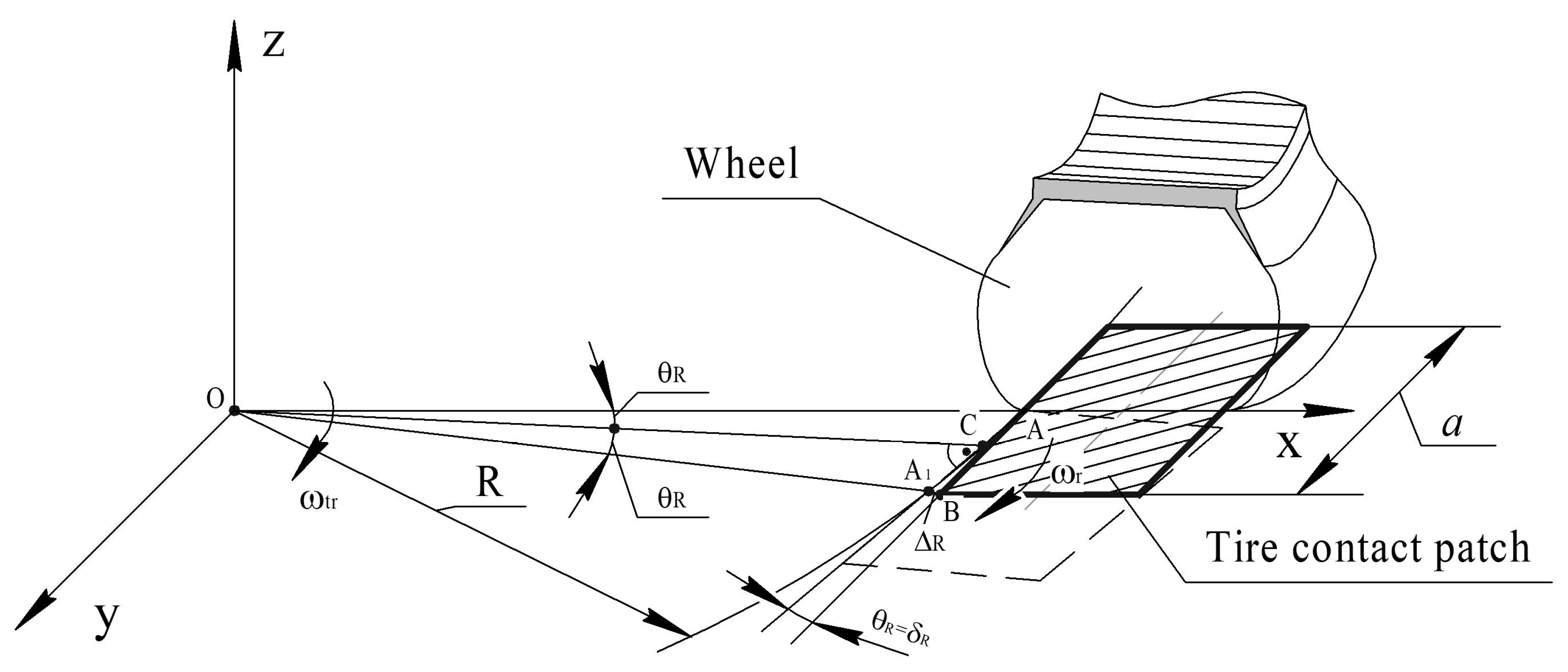
Taking into account the above,
Figure 2 presents a scheme for determining the angle of relative rotation of the contact patch of the tire and its lateral displacement relative to the wheel disc during the movement of the elastic wheel along a curvilinear trajectory.
The contact tire patch of the elastic wheel has the shape of a rectangle, the same size as the tire patch with the longitudinal axis, as can be seen in the analysis in
Figure 2. Point O is the center of the transfer movement of the contact tire patch, relative to which the center of relative rotation of the patch, point A, moves in a circle with a radius
R, with an angular velocity of
ωtr. At the same time, the tire patch turns relative to the center of relative turning, point A, with an angular velocity of
ωr. After passing through the center of the wheel of distance
a/2, the center of relative rotation will take position A
1, and the contact tire patch will take the position shown in
Figure 2 by a dashed line. Angle
θR between these two positions will be the twisting angle of the disc with respect to the tire patch during the movement of the wheel along a curved path of radius
R.
Because
A
1AB =
AOC, as angles with mutually perpendicular sides, then their values are determined by the expression:
where
θR is the twisting angle of the disc relative to the tire patch while the passing through the center of the wheel by the distance
S =
a/2, rad;
a is the tire patch length, m;
R is the radius of the trajectory of the center of relative turning of the tire patch, point A, m.
The turning of the disc relative to the tire patch by an angle
θR will cause a moment of turning resistance relative to the vertical axis passing through the center of the relative turning of the tire patch, point A. We define this moment as follows:
where
Mθ is the moment of turning resistance of the disc, N·m;
Cθ is the angular stiffness of the tire relative to the vertical axis of the wheel passing through the center of the tire patch, N·m/rad. In the absence of experimental data, it is recommended to determine the angular stiffness of the tire according to empirical dependence
Cθ = (0.51-0.63)
Gw, N·m/rad, where
Gw is the load on the wheel, N. At the same time, lower values refer to high-pressure tires and larger ones to wide-profile tires with adjustable air pressure.
At the same time, after passing through the center of the wheel by the distance
S =
a/2, point A will shift in a lateral direction relative to the initial position of the tire patch by Δ
R = A
1B. By this amount, the disc of the elastic wheel will shift in a lateral direction relative to the initial position. The value of this displacement is determined by the following expression:
The lateral displacement of the disc by the amount Δ
R will cause the wheel to roll with slip angle
δR, which, according to
Figure 2, is equal to angle
θR, and cause the appearance of a lateral force, which, taking into account the accepted assumptions, we write as follows:
where
PS is the lateral force that occurs when the disc is displaced laterally during its passage through the center of the wheel along the circle of the path
S =
a/2, N;
δR is the slip angle, which is caused by the rolling characteristics of an elastic wheel along a curved path with a radius of
R, rad. This slip angle is usually called “kinematic”;
KS is the coefficient of lateral deflection, N/rad.
As for the lateral force, it is located in a plane perpendicular to the rolling plane of the wheel. The analysis of the research results presented in references [
25,
27] proved that when the wheel moves along a curved path, the energy supplied to the wheel disc due to the pushing force from the vehicle frame or due to the torque from the transmission is distributed equally to the twisting of the disc and its lateral displacement relative to the tire patch. In this case, if the angles
θR =
δR =
a/4
R, the coefficient of lateral displacement, according to [
25], is determined by the following expression:
It follows from this that the movement of an elastic wheel along a curved path will cause, in addition to rolling resistance along a straight path, resistance due to the twisting of the tire body between the hard disc and the patch and the lateral displacement of the disc relative to the patch. The twisting of the tire body will cause a moment of the vertical axis passing through the center of relative turning of the tire patch, and the lateral displacement will cause a lateral force. Evidently, in order to ensure the movement of an elastic wheel along a curved path with a radius R, it is necessary to supply energy to the wheel disc to overcome the rolling resistance and ensure the turning of the disc by the angle θR and its lateral displacement by the amount ΔR relative to the tire patch. At the same time, the pushing force of the car frame and the torque applied to the wheel disc act in the plane of its rolling.
The presence of an amorphous body of the tire and different planes of action of these three dynamic factors indicate the peculiarity of the phenomena occurring in the body of the tire when moving along a curved path, and cause difficulties in calculating the motion resistance coefficient of the wheel along a curved path.
The movement of the wheel along a curved path in the absence of an inclination to the support surface, which is typical of non-steered wheels of vehicles, was considered above. However, the presence of steered wheels, which turn relative to the axis of the kingpins with a transverse and longitudinal inclination, causes them to roll with an inclination relative to the support surface. As a result of the research carried out in [
27], it was determined that when an elastic wheel with an inclination towards the road moves along a curved path, the phenomena caused by the rolling of the inclined wheel are additionally superimposed on the phenomena occurring in the pneumatics (tire bodies) during movement along the curved path. With an unchanged trajectory in the elastic wheel, they cause a change in the slip angle of the pneumatic tire and a lateral displacement of the disc relative to the tire patch.
To determine the influence of the inclination of the wheel to the road during movement along a curved trajectory, according to [
27], the concept of “reduced” radius of curvature of the trajectory of the elastic wheel is introduced. It is understood as the conditional radius of the trajectory of the wheel movement, with which the wheel would move without tilting along a curved trajectory, but with the twisting angle and lateral displacement, which take into account the phenomena accompanying the rolling of the wheel along a curved trajectory and with an inclination to the road.
At the same time, the direction of the inclination of the wheel relative to the center of its turning is of significant importance, and the dependencies obtained in [
27] make it possible to determine the value of the twisting angle of the tire body and the lateral displacement when the wheel moves with an inclination to the road along a curved trajectory.
If the wheel has an inclination, then the kinematic slip angle, according to [
27], is determined by the following expression:
where Σ
δR is the kinematic slip angle when rolling the wheel, with an inclination (with camber) to the road, rad;
rw is the rolling radius of the wheel, m;
γ is the current camber angle, deg.
Note that in Expression (19), the “plus” sign is used for the case when the wheel is tilted away from the center of rotation, and the “minus” sign is used when it is tilted toward the center of rotation. In this case, a “plus” sign is used with the camber angle γ.
As for the current camber angle of the wheel, it is a function of the transverse and longitudinal inclination of the kingpin and the camber angle in the position of the straight-line movement of the vehicle, and is determined by the following expression [
27]:
where
γ0 is the camber angle of the wheel in the position of rectilinear movement, rad;
αt,
βt are angles of transverse and longitudinal inclination of the kingpin, rad.;
θ is the current angle of the turning of the wheel in degrees.
In Expression (20), the “plus” sign must be used when the left-steered wheel is turned to the left from the position of the car’s straight-line motion, and the right wheel is turned to the right. If otherwise, the “minus” sign should be used.
If the wheel with an inclination to the road moves along a curved path with a kinematic slip angle Σ
δR, then, taking into account the Expression (14) and the above, we write:
Using Expression (21), we have determined the “reduced” radius of curvature of the trajectory of the wheel with an inclination (camber) to the road:
where
Rr is the “reduced” radius of the wheel’s trajectory in the presence of the camber angle
γ, m;
R is the radius of the trajectory of the wheel in the absence of a camber angle, m.
If the vehicle is equipped with paired wheels on the rear axles, then the patches of the two tires of these paired wheels are reduced to a rectangle of equal size.
It follows from the above that the wheel motion resistance along a curvilinear trajectory consists of the resistance along a straight path, which will be determined by the rolling resistance coefficient f and the resistance caused by the simultaneous twisting and lateral displacement of the disc relative to the tire patch. This additional resistance will be determined by an increase in the wheel motion resistance coefficient along a curvilinear trajectory Δf.
Given that the curvilinear motion is characterized by the twisting angle of the disc and the kinematic slip angle, which are equal in absolute value to each other, we will look for a functional relationship between an increase in the motion resistance coefficient along a curvilinear trajectory and the kinematic slip angle, taking into account the shape of the contact patch and the angular stiffness of the tire. The motion resistance coefficient along a curvilinear trajectory will be determined by the following expression:
where
fR is the motion resistance coefficient along a curvilinear trajectory;
f is the rolling resistance coefficient along a straight line; Δ
f is the increase in the motion resistance coefficient along a curvilinear trajectory.
Taking into account that the moment of the motion resistance exists along a straight line, the lateral force and the moment from twisting the body of the tire when moving along a curvilinear trajectory act in different planes; the increase in the motion resistance coefficient along a curvilinear trajectory Δf can only be determined experimentally.
4. Discussion
Motion resistance is a significant factor that affects the fuel economy of vehicles. Total motion resistance along a curvilinear trajectory consists of the resistance along a straight path, which is determined by the rolling resistance coefficient, and an additional resistance caused by the simultaneous twisting and lateral displacement of the disc relative to the tire patch. The determining characteristics that form the value of the coefficient of rolling resistance when moving in a straight line on an asphalt concrete surface are the design features of tires, which include: the presence of a metal cord in the tire shell, the number of layers of the cord and its material, the type of tread (summer, winter, and presence of metal spikes), the height and saturation of the tread pattern, the construction of the cord (diagonal and radial), the presence of tubes, the area and shape of the tire’s contact patch, etc.
According to Empirical Dependences (1)–(3), the influence of speed on the coefficient of rolling resistance is determined by a linear law. These dependencies do not take into account the experimental value of the rolling resistance coefficient at low speed. The given empirical dependences for determining the rolling resistance coefficients (7), (8), (11), and (12) contain their experimental values at a movement speed close to zero, and the influence of movement speed is described by a parabolic law.
It was established that smaller values of the rolling resistance coefficient are typical of tubeless tires with a metal cord shell, and larger values are typical of tires with adjustable air pressure.
As research shows, the resistance in curvilinear motion mainly depends on the vehicle layout and the characteristics of the installed tires. The characteristics of tires differ in the elastic properties, shape, and size of tire contact patches. The experimental study was carried out using such vehicles as example: two front-wheel drive vehicles, rear-wheel drive vehicle with dual wheels on the rear axle, and a four-wheel drive vehicle. The following types of tires were installed in the mentioned vehicles: Nokian WR 205/60 R16 tires (NOKIAN TIRES, Vsevolzhsk, Russia), with the dimensions of the contact patches of the front wheels being a = 0.109 m, b = 0.151 m, and the dimensions of the rear wheels being a = 0.102 m, b = 0.150 m; Sava 175/65 R14 tires (T.C. DEBICA S.A., Debica, Poland), with the dimensions of the contact patches of front wheels being a = 0.16 m, b = 0.14 m, and the dimensions of the rear wheels being a = 0.122 m, b = 0.125 m; Goodyear Eagle 225/55 R18 tires (SUMITOMO RUBBER INDUSTRIES, LTD, Toyota, Japan), with the dimensions of the contact patches of the front wheels being a = 0.125 m, b = 0.17 m, and the dimensions of the rear wheels being a = 0.124 m, b = 0.16 m. The vehicle with dual wheels on the rear axle was equipped with Rosava 185/75 R16C tires (ROSAVA, Bila Tserkva, Ukraine), with the dimensions of the contact patches of the front wheels being a = 0.147 m, b = 0.128 m. For the paired rear wheels, the internal dimensions were as follows: a = 0.115 m, b = 0.129 m. The external dimensions were as follows: a = 0.106 m, b = 0.121 m. Thus, the selected vehicles, as research objects, take into account typical two-axle vehicle layouts and different types of tires.
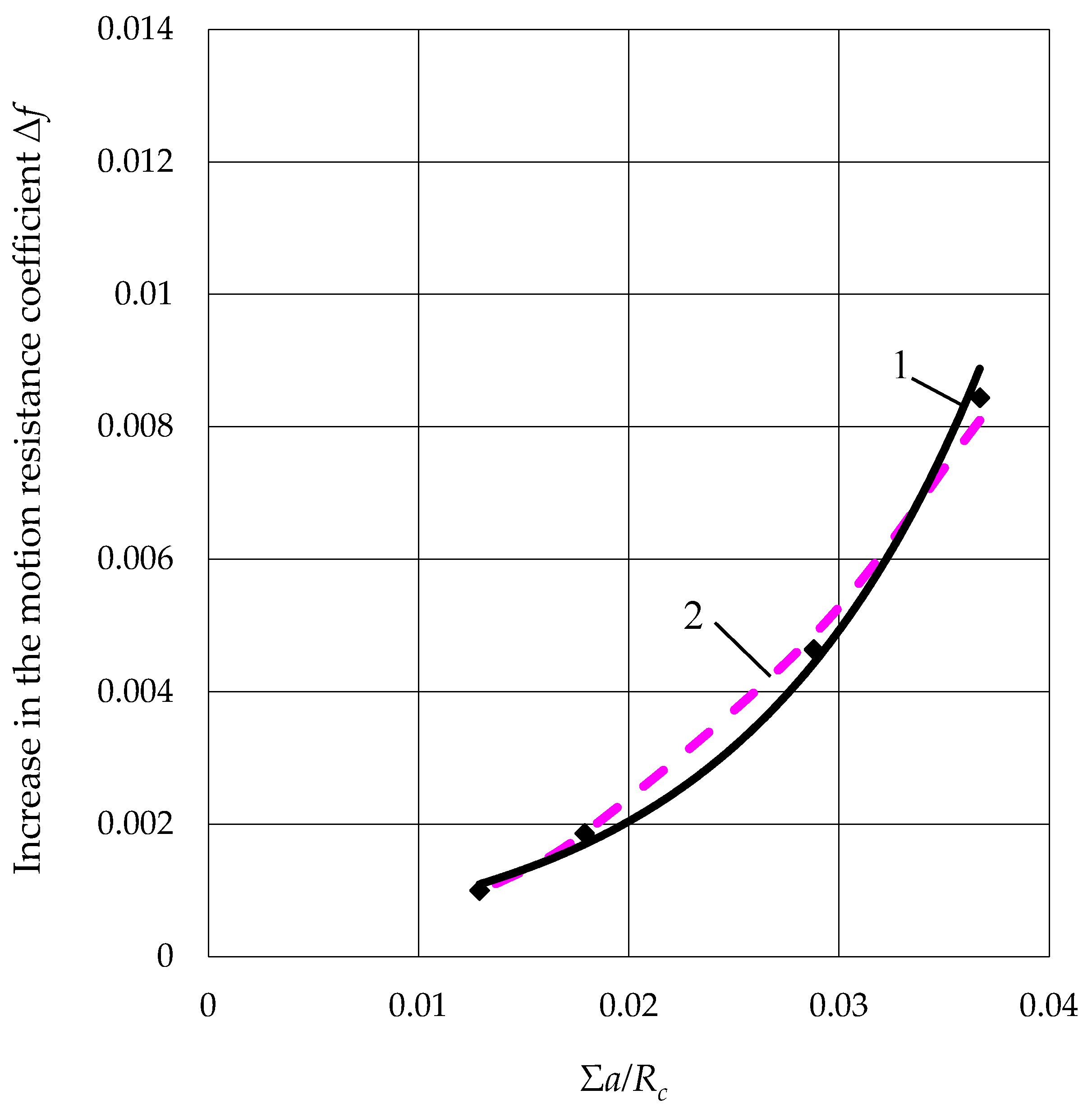
During the motion of the wheel along a curved path, there is simultaneous twisting and lateral displacement of the disc relative to the tire patch, which cause a twisting moment and a lateral force. These dynamic factors lie in planes perpendicular to the rolling plane of the wheel and cause additional resistance to the motion of the wheel, which is characterized by the increase in the motion resistance coefficient. An empirical dependence was obtained for its determination, whose value is directly proportional to the dimensions of the tire contact patch, the angular stiffness of the tire, and is inversely proportional to the radius of curvature of the trajectory. At the same time, this coefficient is a function of the kinematic slip angle and changes according to the parabolic law, and the parabola parameter takes into account the stiffness and the shape of the tire’s contact patch. Its value is affected by the ratio between the transverse and longitudinal axes of the tire contact patch. An increase in this ratio causes a decrease in the parabola parameter. The obtained experimental values of the parabola parameter for the considered tires are within 12–17.5.
It has been established that for two-axle wheeled vehicles with sufficient accuracy for practice, it is recommended to determine the increase in the motion resistance coefficient based on the trajectory of the wheel brought to the center of mass of the wheeled vehicle. When moving along a curvilinear trajectory with a minimum radius, the motion resistance coefficient increases by 1.68–2.04 times in relation to the straight-line motion.
Further research will be directed towards the study of three-axle vehicles with a tandem axle group, which leads to a significant increase in the motion resistance along a curved trajectory. The results of these studies on the total resistance of curvilinear movement will be useful for specialists in the field of improving the energy efficiency of vehicles.


 ,
, 


