Article

Simulative and Experimental Investigation of the Ring Creeping Damage Mechanism Considering the Training Effect in Large-Sized Bearings

Thyssenkrupp Rothe Erde Germany GmbH, Beckumer Str. 87, 59555 Lippstadt, Germany
*
Author to whom correspondence should be addressed.
Machines 2023, 11(5), 543; https://doi.org/10.3390/machines11050543
Submission received: 13 April 2023 / Revised: 8 May 2023 / Accepted: 8 May 2023 / Published: 11 May 2023
(This article belongs to the Special Issue Friction and Lubrication of Mechanical Drive Train Components)

Abstract

:
In this work, an advanced, numerical simulation method based on finite element analyses was developed in order to simultaneously take into account both roller- and structural-induced ring creeping phenomena. Ring creeping in general refers to a failure mode caused by a (non-bolted) bearing ring rotating relatively to its adjacent component such as, e.g., shaft or housing during operation. In particular, the coefficient of friction at the contact interface between bearing ring and adjacent component has a crucial influence. In order to consider this effect, a bearing ring creeping test rig based on component-like specimen was developed. Experimental results with respect to (i) measured creeping parameters such as creeping distance and (ii) the coefficient of friction due to run-in effects were described. Finally, experimental and numerical results were compared qualitatively to approve the reasonableness of the simulation model. The developed simulation approach enables the consideration of the entire drive train system within the micro-scale creeping evaluation procedure and therefore supports both drive train and bearing design-specific optimization measures in order to increase the reliability and robustness of a main bearing arrangement.

1. Introduction

Within the past 30 years, different drive train arrangements have been realized. The single momentum bearing is widely used in direct drive train arrangements. This self-retaining momentum bearing is a one-piece component, ready to install, and shows excellent operational performance. A characteristic feature of this bearing type is that the rings are attached to the companion structures by preloaded bolts. Another well-suited alternative is to split the double-row momentum bearing into two separated single bearings. This kind of bearing arrangement is mainly used in geared machines. Preloaded tapered roller bearings (TRB) are excellently suited for this purpose due to their high load capacity, stiffness, and adaptability. However, the inner and outer rings of these bearings are usually clamped to the companion structure. Consequently, TRB-TRB arrangements are very sensitive to the drive train assembly, which is why higher requirements are set regarding the design and the calculation process [1,2].
In particular the failure mode “ring creeping” is design-critical for non-bolted large-sized diameter rotor main bearing applications, since it can lead to fretting corrosion and/or abrasive wear between bearing ring and shaft (respectively housing) as shown in Figure 1 [3].
Ring creeping in general refers to a failure mode caused by a bearing ring rotating relatively to its adjacent component during operation. This ring movement as a result of the accumulated micro slip occurs due to a local partial reduction or even an entire loss of the contact pressure within the joint. The origin of the pressure loss can be demonstrated most simply using a two-dimensional roller bearing as shown in Figure 2. The simplified model shows that the pure radial load of the roller forces (static bearing condition) causes a wave-like deformation (see Figure 2a). Below the roller, this leads to an increase in the frictional shear stress and at the same time to a reduction of the contact pressure (or even in the worst case to a gap between the ring and bearing seat) in the intermediate area between the rollers. If the frictional contact is exceeded, local slippage occurs. In combination with rotating rollers (rotating bearing condition) this leads to a tangential elastic deformation in the load-free area between two rollers. If the friction limit is exceeded in that area, this leads to a displacement of the compressed part of the bearing ring by a few μm in the tangential direction (see Figure 2b). As this process takes place continuously, the resulting displacements add up to macroscopically visible relative displacements Δ between the bearing ring and adjacent construction. In summary, this means that the occurrence of relative movements depends primarily on the coefficient of friction (COF) within the joint as well as on the local radial and shear stresses. These local stresses are caused by the contact pressure of the interference fit and additionally either by the roller elements itself (roller-induced creeping; see Figure 2) or by the deformation of the adjacent drivetrain components (structural-induced creeping) [5,6].
Both causes have been investigated in detail on small-sized bearings by means of analytical approaches, experiments and finite element (FE) simulations [7,8,9,10,11,12,13,14,15,16,17,18]. The proposed procedure of a 3D kinematic finite element analysis can be used to analyze the physical creeping effect and provides a quantitative evaluation of the creeping behavior. Moreover, it also enables the comparison of different countermeasures against creeping [6].
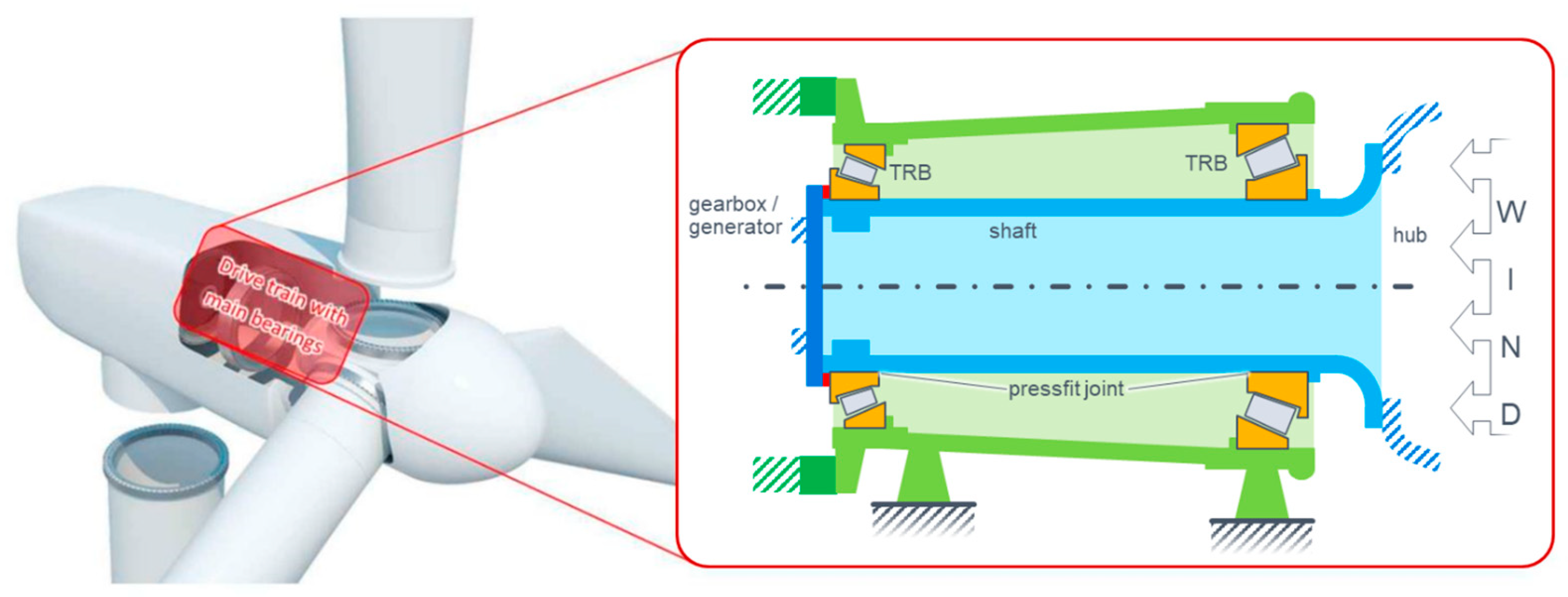
As these kinematic simulations are very complex and time-consuming a simplified (and thus faster) calculation tool “SimWag” was developed by the “Research Association for Drive Technology” (FVA) to predict the creeping tendency. This qualitative prediction method is based on a binary slip criterion that was calibrated using kinematic simulations and experiments. The SimWag result only allows the statement of whether creeping occurs or not. It does not provide any information on how the creeping behavior looks in detail. This lack of detail hampers a reliable design process and a detailed evaluation of bearing and drive train design-specific countermeasures. In addition, the simplified prediction method of SimWag was only validated up to a bearing diameter of about 500 mm. Therefore, the application for large-sized bearings is associated with uncertainties. This is particularly crucial since large-sized bearings tend to be more critical with regard to creeping anyway. This is due to the fact that the micro-movements are roughly proportional to the size of the bearing, so the creeping-critical “threshold values” of the slip, which are to be regarded as absolute values, are already reached at lower loads. In addition, the rings of large-sized bearings are—compared to smaller designs—relatively thin-walled due to weight reasons, which reduces the relative stiffness as well as the joint pressure as a result of the smaller relative oversize [8]. These entire effects specific to large-sized bearings promote creeping, which is why an advanced (and at the same time efficient) simulation method is required for large-sized rotor main bearing applications as shown in Figure 3 [9,11].
Since the investigational workload increases significantly with increasing bearing size, experimental as well as simulative creeping investigations on slewing bearings are very rare. Besides, the increase in the COF—the so-called training effect [8] —has not yet been considered in detail in the kinematic simulations and has not yet been sufficiently answered in the literature [3,5,17,18,19,20,21]. It is generally assumed that during the friction training, the initial COF in the contact interface is significantly increased due to (micro) wear, which can be observed in Figure 1. In this process, the metal particles extracted from the surface oxidize. Since the reaction products are more voluminous than the starting material, tensile residual stresses occur in the adjacent metal parts [21]. This leads to a tighter interlocking of surfaces by clawing- and/or micro-welding effects. As a consequence, it is possible that the wear particles remaining in the contact joint stop the creeping movement [3,22]. However, the question remains unanswered why the friction coefficient on conventional friction test rigs, in which two specimens are repeatedly twisted against each other by a few degrees, does not provide the same friction coefficient as it does after creeping [4,9].
Therefore, it is essential to take into account the training effect due to creeping at any creeping simulation. This can be done either by an integrated wear simulation or by considering the trained friction coefficient, which has been previously determined on a creeping test rig. The consideration of the measured coefficient of friction in the creeping simulation has the big advantage that the training mechanism does not have to be known in detail and no wear model has to be developed for it, but nevertheless, the effect is completely represented.
Accordingly, this paper experimentally and theoretically investigates the ring creeping damage mechanism in large-sized rotor main bearings. Since the knowledge gained so far has not addressed the training effect in detail and since the transfer of small to large bearing arrangements is only partially valid, this must be investigated explicitly. Thereby, the focus is experimentally on the measurement of the creeping movement as well as the training effect and numerically on an efficient FE modeling.

2. Developed Procedure

In order to cope with the above-mentioned challenges regarding the creeping of slewing bearings, an advanced numerical simulation method was developed. Therefore, a structured procedure is shown to observe the test rig and simulation results of creeping, including the training effect.
In this procedure, a test assembly (consisting of a shaft and inner ring) is at first mounted on a creeping test rig. The external load is afterward varied until permanent creeping movements are measured (see Section 3.1). During this test rig run, the creeping movements simultaneously train the COF in the contact joint. The load at which the permanent creep finally occurs is referred to as the creeping limit and it can be used as a benchmark for the FE simulation. In addition, the COF of the test assembly—representing the trained or run-in contact conditions—is determined on a different test rig (see Section 3.2) and is used as an input variable for the simulation. So the physical creeping behavior can be modeled more realistically (see Section 4). The FE simulation itself was configured in such a way that no settings or parameters (e.g., contact or mesh settings) were aligned or calibrated with the test rig measurements (see Section 4.1). As a result, a numerically consistent simulation model was developed, which is independent of any experimental calibration, and thus the scope of application is not limited. This allows a suitable comparison of experimental and numerical creeping results (see Section 4.3).

3. Experimental Investigations

Extensive tests were carried out on a newly designed creeping test rig (see Section 3.1) on which ring creeping can be generated and measured. The generic design of this test rig and the appropriate accessibility of the measurement sensor system allow an in-depth investigation of the ring creeping phenomena. Therefore, it provides suitable prerequisites for determining necessary input variables for the numeric simulation and a detailed investigation of the influence of parameters (such as surface quality, material pairing, surface hardness, etc.) on the ring creeping tendency of large-sized bearings. In contrast to common dynamic friction tests, the follow-up tests on the COF test rig (see Section 3.2) at thyssenkrupp rothe erde OU Germany (abbr.: tkre), allow the determination of the increased COF of the trained specimen for a subsequent application in the numerical simulations [4].

3.1. Creeping Test Rig

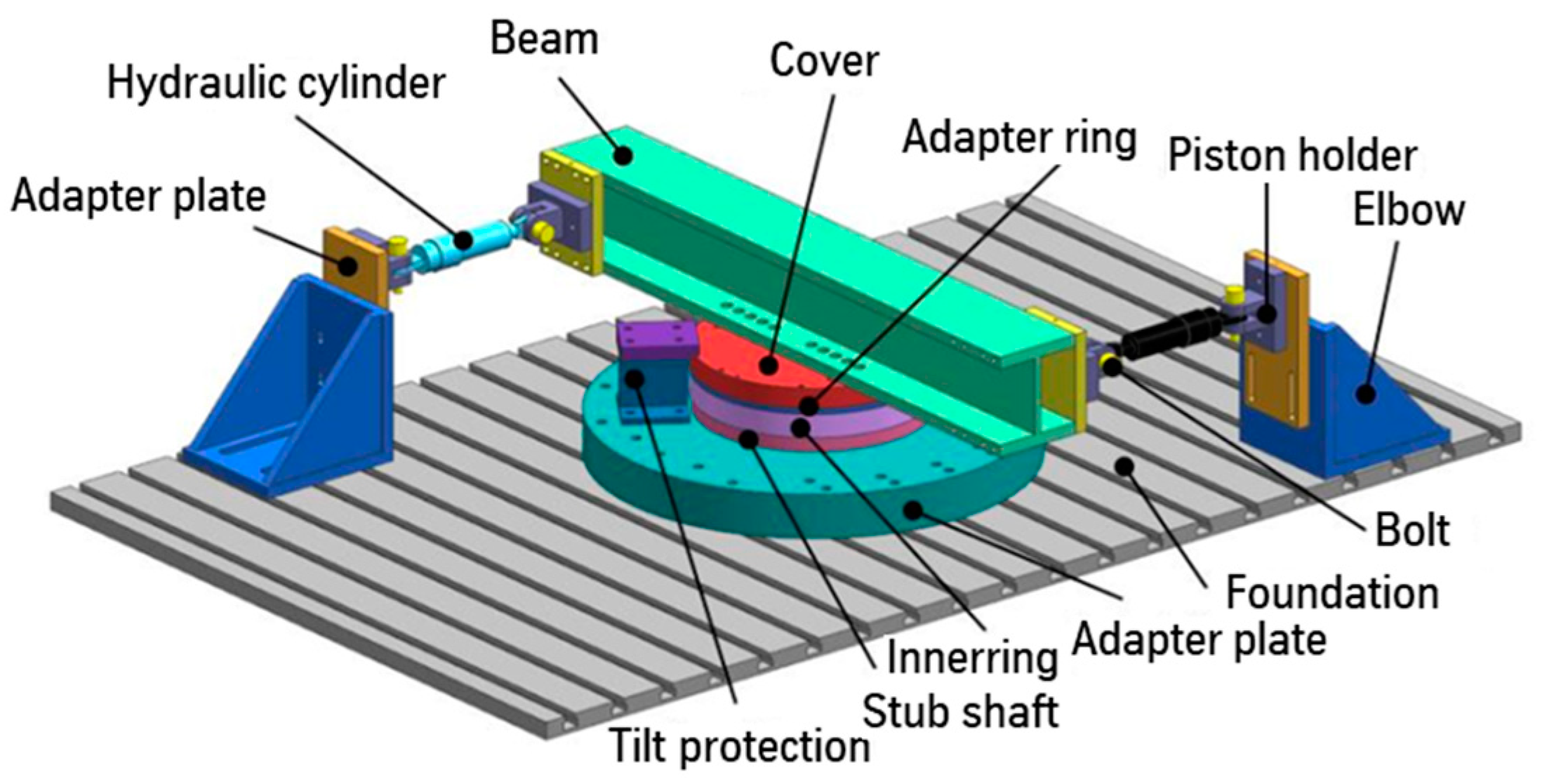
To enable an isolated investigation of the ring creeping of a large-sized bearing (detached from the global system behavior), a new creeping test rig has been developed, see Figure 4.
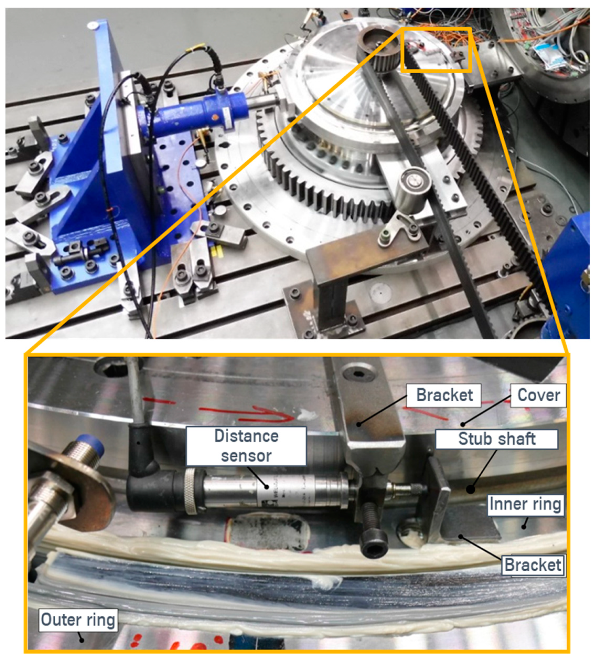
The test specimen, shown in green, consists of a cast iron shaft with a cylindrical roller bearing. The inner ring of the bearing together with the shaft (interference fit) is rotating; the outer ring of the bearing stands still. The radial load is induced using a hydraulic cylinder, which is pressed onto the outer ring of the bearing. To measure the relative (circumferential) movement between the shaft and the inner ring, the inductive displacement measurement (position sensor) of Figure 5 is used.
Figure 6 shows the measurement curves of a typical test scenario to investigate the ring creeping of one inner ring/shaft configuration. In the upper part of the figure, the applied force by the hydraulic cylinder is plotted over time. Below the measurement signal of the creeping sensor is illustrated. In the first test, the bearing ring starts creeping at about the green line. It can be noticed, that the passed creeping distance of the bearing ring is increasing for each load step. If the test (re-run) with the identical inner ring/shaft configuration is repeated, the radial load to trigger ring creeping is increasing. The reason for that is the training effect, which leads to an increased COF between the bearing ring and the adjacent component.

3.2. Coefficient of Friction (COF) Test Rig

The COF test rig allows the determination of the increased COF of the trained specimen, thus a differentiation between an increase in the COF due to real training by creeping and an increase in the COF due to conventional abrasive wear processes (common dynamic friction tests) is made possible. During the test, the shaft is bolted to the foundation, and the inner ring is moved in the circumferential direction by the hydraulic cylinders as shown in Figure 7. By measuring the necessary force (respectively the moment M) to initiate a defined relative movement, the integral COF µF for the design process is calculated according to Equation (1) [23].
µF = (2 × M)/(dF × NF)
The joint diameter dF for the test configuration is 725 mm. The nominal force NF of the interference fit can be calculated using the joint pressure pF and the bearing width LF of 80 mm as shown in Equation (2):
NF = π × dF × LF × pF
The joint pressure pF itself was determined for different oversizes via a separate static FE simulation.
The force required to rotate the inner ring and the tangential ring movement of the inner ring/shaft configuration of Section 3.1 is illustrated in Figure 8. In the first test, the force required to rotate the inner ring is approx. 118 kN. In all subsequent tests, the force required to rotate the inner ring is at a load level far below the force of the trained conditions (approx. 72 kN). It can thus be concluded that there is already a change in the parting line during the first COF test, which reduces the coefficient of friction compared to the trained condition.
By using the presented test strategy, it is possible to evaluate the ring creeping tendency i.e., for different surface qualities or material pairings. In addition, the increase of COF as a corrective action against ring creeping (i.e., due to different surface qualities) becomes experimentally quantifiable. For example, a trained blasted inner ring surface has an increase in COF of approx. 38% compared to a trained common turned surface. Furthermore, the determined COF is a necessary input value of the following advanced numerical simulation method.

4. Numerical Simulation Method

To facilitate an analysis of the physical creeping effect on the micro-scale level while at the same time modeling the relevant drivetrain behavior on a component scale level, the simulation approach is to be defined suitably. Therefore, a simulation model was developed that is based on a nonlinear, static transient structural analysis. The goal was to develop an FE model that is inherently consistent without experimental calibration. The test rig measurements are thus available for an unbiased comparison of the numerical results.

4.1. Finite Element Model Setup

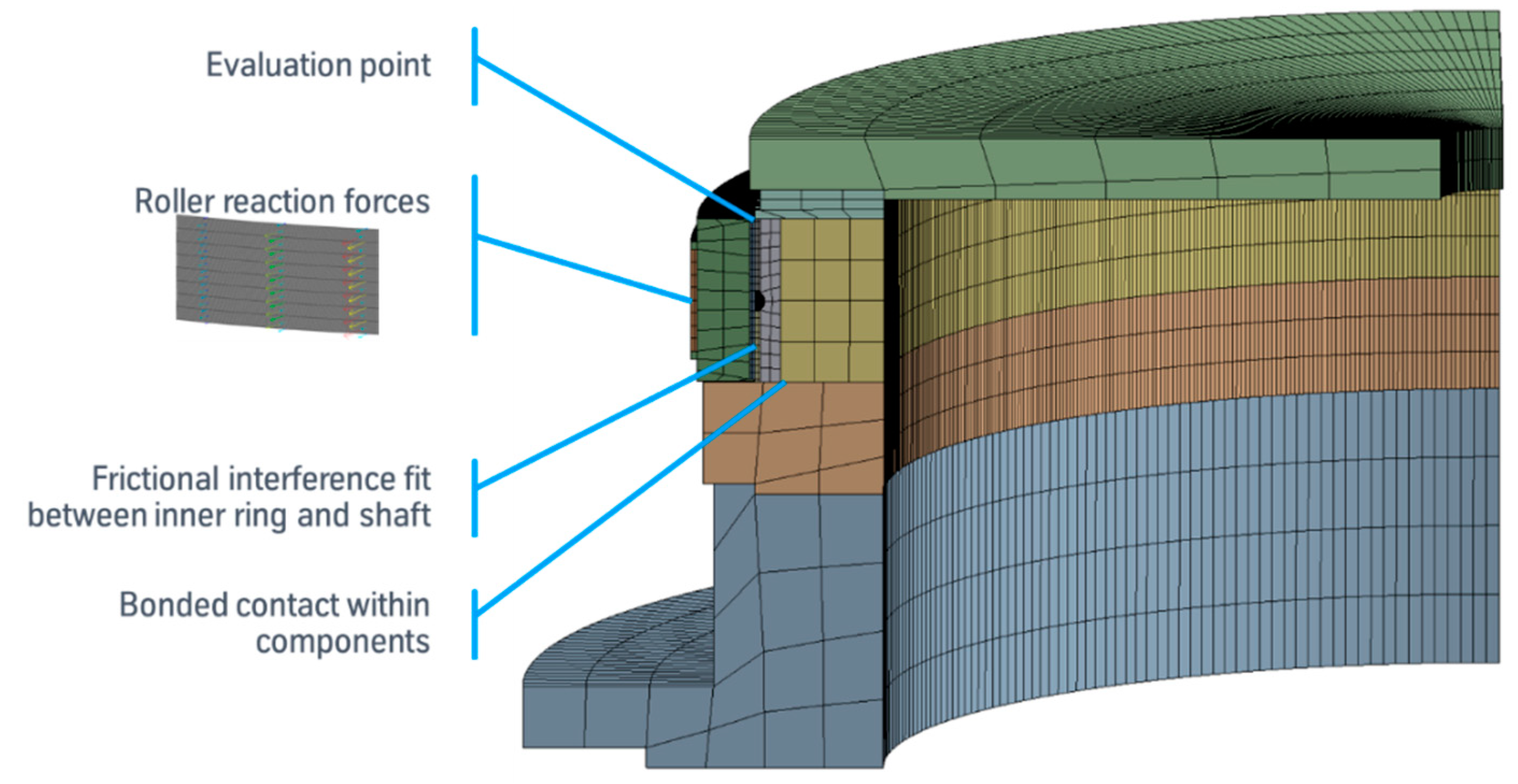
Due to the complexity of the creeping simulation, the model setup must be as efficient as possible. Therefore, only the contact joint and the adjacent test rig components (bearing inner ring and shaft) are modeled as shown in Figure 9.
Accordingly, the rollers are not modeled either, but substituted by the corresponding contact forces. These forces are applied automatically rotating in several steps via a proprietary script representing the line contact between the roller and the raceway. Since the rollers themselves are accordingly not included as a solid model, only the corresponding reaction forces can be shown in the small subfigure of Figure 9. The reaction forces plotted for three rollers highlight the modeled line contact between the raceway and roller. This modeling technique reduces the simulation effort and improves the convergence behavior since no (connecting) elements for the rollers and no contact conditions between the rollers and the raceway are needed. The applied load distribution itself is determined previously by means of a static finite element analysis considering all test rig components.
The FE mesh also focuses on the contact joint between the bearing ring and the shaft. For this purpose, each elastic FE body is divided and recombined via bonded contact. This can be exemplarily shown in Figure 9 by the component of the stub shaft (refer to Figure 4). This component was initially divided into 5 parts within the computer-aided design (CAD) model. Afterward, these parts could be meshed separately and then reconnected via bonded contact so that they are treated as one component again within the simulation. On the one hand, this ensures that regular hexahedral meshes are generated. On the other hand, it enables the variation of the mesh size within a component over a wide range: For example, the domain of the contact joint has a very fine mesh size, whereas remote domains are meshed coarser—but still in sufficient detail for an adequate stiffness representation. All these stepwise simplifications of the model are necessary in order to simulate creeping at all in the case of large-sized bearings with regard to memory and time requirements and were confirmed by convergence studies.
Each simulation run consists of three main steps:
  • Boundary conditions of the interference fit: The interference between the bearing ring and the shaft is not modeled geometrically. Instead, it is integrated into the contact condition as an initial penetration that is zeroed out gradually. During this first step, the friction is deactivated so that a condition without frictional shear stress ensues;
  • Frictional contact condition and external load: The contact condition in the joint is set from frictionless to frictional by using the trained COF. The initial load distribution of the bearing is applied as radial forces. As an alternative or in addition, any other external loads that occur (periodically) can also be applied. Thus, it is possible to simulate structural-induced creeping as well;
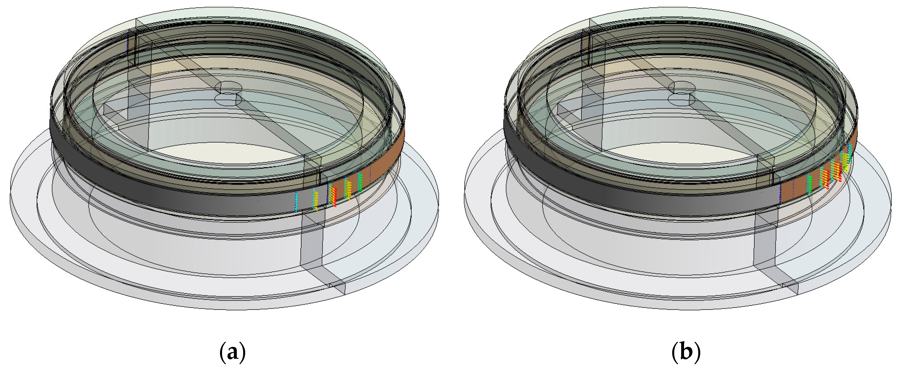
  • Load stepwise rotation of the roller forces: During this calculation sequence, the previously stationary bearing model is set in motion by rotating the radial forces by a defined angle at each load step. This stepwise rotation of the load distribution isshown in Figure 10 for two different calculation increments.

4.2. Exemplary Simulation Results

This described simulation run is mainly characterized by the contact of the interference fit. During the overrollings, the contact status between the component facets in the joint alternates between sticking and sliding. This frequent change necessitates well-adjusted contact parameters: Starting with the contact algorithm, via the contact stiffness/penetration to a suitable contact search, all parameters are to be aligned. These configurations were tested by means of parameter studies for convergence independently as well as in their combination and were adapted to the mesh and step size. Especially the mesh and step size of the calculation are important setting parameters that have to be defined according to the number of rollers and the bearing size in order to ensure numerical convergence and physically reasonable results. If the finite element model is configured suitably, the result shown in Figure 11 can be obtained after a calculation run.
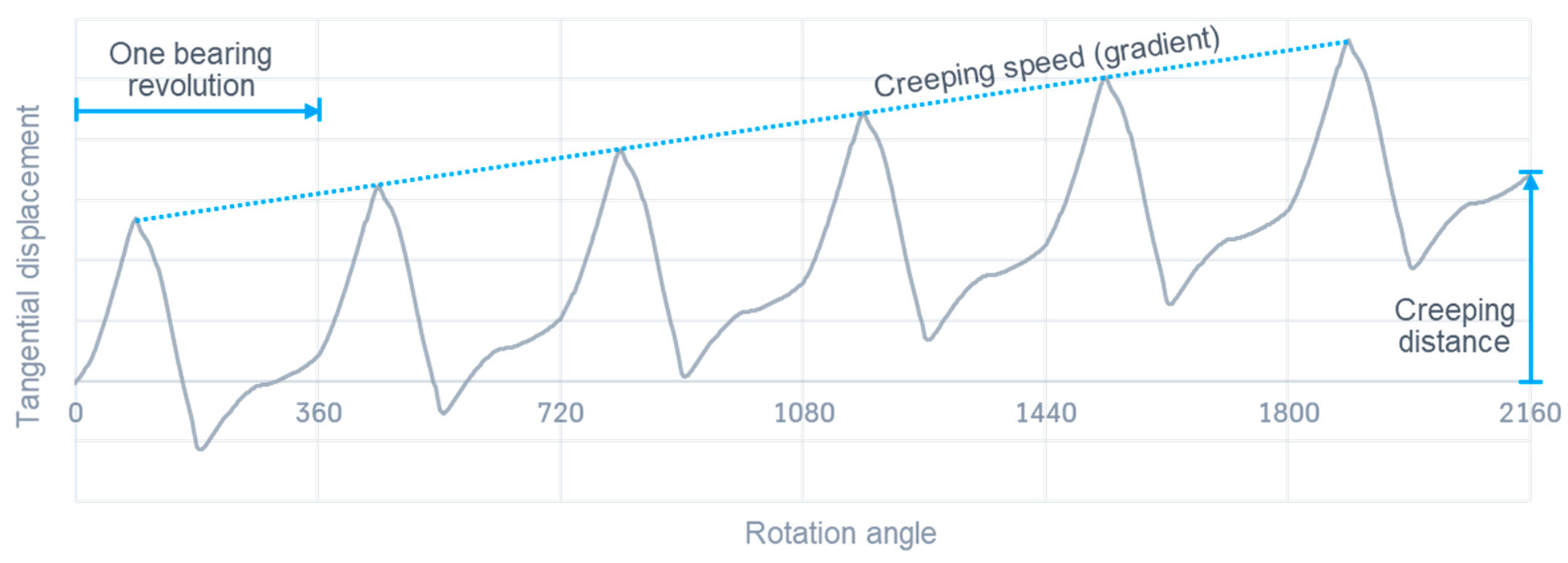
The plotted tangential displacement of an evaluation node shows a pattern that repeats itself with each bearing revolution. Whether creeping occurs is indicated by the resulting displacement at the beginning and after one bearing revolution. The persistent displacement represents the creeping distance and the creeping speed can be determined by the gradient of the displacement graph. If no displacement persists, no creeping has occurred. Nevertheless, the characteristic displacement pattern can (but does not have to) exist, but at a creeping speed of zero.
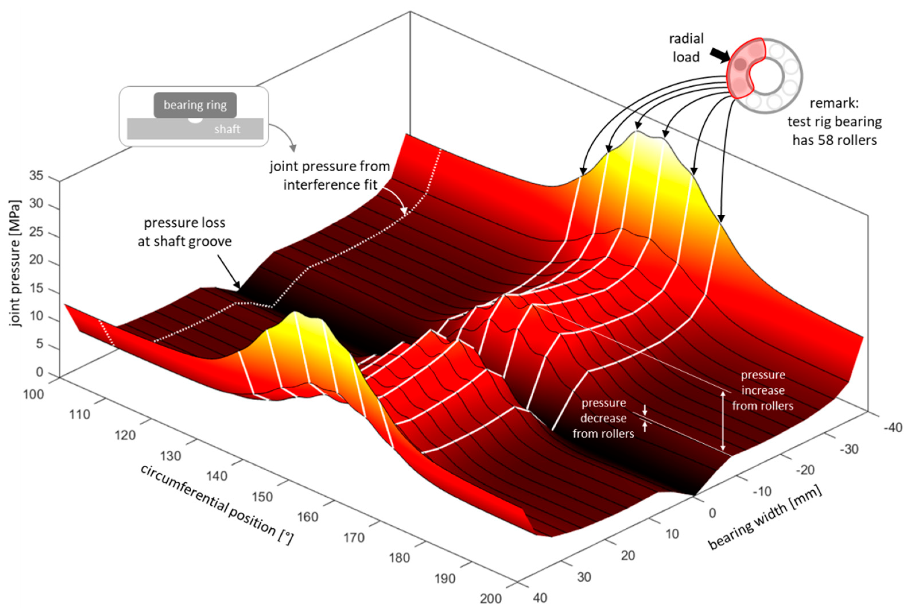
Besides the physical creeping kinematics, the simulation can also be used to examine other interim results, which help to evaluate the joint. For example, the pressure distribution within the joint can be investigated in detail. Figure 12 shows the contact pressure resulting from the interference fit and the applied roller forces.
In the width direction, the typical pressure distribution of interference fits can be seen. The white dotted line highlights the pressure distribution at the circumferential position of 110 degrees, which is far away from the load zone (Figure 12: circumferential position of about 140 to 170 degrees). At this position, the resulting pressure distribution is purely due to the interference fit and shows the typical bathtub shape. The pressure loss at the center of the bearing is due to a groove in the shaft, which is required to disassemble the bearing from the shaft. At the load zone, the pressure distribution of the interference fit is superimposed by the influence of the roller forces. Accordingly, there is an increase in the pressure level right below the rollers (white lines). Between two rollers, the wave-like pattern indicates a slight decrease in the pressure level. Directly next to the load zone (Figure 12: circumferential positions of about 120–130 and 180–190 degrees), there is a decrease in the pressure level. At these two positions, the pressure level even decreases below the pressure value that would be present due to the pure interference fit. Consequently, this reduced contact pressure provides less resistance to circumferential movements. Although the lower pressure level itself is not a sufficient criterion for creeping, it can be used as an indication of critical spots.

4.3. Comparison of Results

The sensor data of the creeping test rig provide the external load at which creeping occurs (incl. creeping speed) as well as the detailed shape of the creeping movement during one revolution. In Figure 13, this characteristic shape is qualitatively compared with the simulation result in order to check the plausibility of the FE modeling. For this purpose, a simulation run was performed with the aforementioned steps and the circumferential displacement at the evaluation point was determined during one bearing revolution. The comparison of both results shows a reasonable similarity between the graphs. Initially, the loaded rollers push the evaluation point forward until the load is on top of it. Afterward, the observed point can move back until the following (less loaded) rolling elements push it slightly forward again. In the following the load zone is far away from the evaluation point, therefore almost no movement can be determined. As soon as the evaluation point re-enters the load zone, the deformation movement starts again from the beginning. If any displacement remains after one cycle, this indicates the permanent creeping movement of the bearing ring. If no displacement remains, no creeping has occurred.

5. Conclusions

In this work, a structured, FE-based procedure is shown to align the test rig and simulation results of ring creeping for a large-sized bearing ring including the so-called training or “run-in” effect. One of the unique aspects is that the training effect is not taken into account using a wear simulation. Instead, a test concept was developed that enables the measurement of the trained coefficient of friction, which subsequently is used as an input parameter in the creeping simulation. In addition, the FE setup of the creeping model was optimized so that the friction-increasing training effect could be adequately taken into account at large-sized bearings for the first time. The procedure also allows detailed insight into the contact interface and thus provides a deeper understanding of the ring creeping damage mechanism.
An initial comparison between the creeping results of the test rig and the FE simulation model shows similar results with respect to the evaluation of the creeping movement. The simulation approach shown has the general advantage that the scope of application is not limited and thus further drive train components can be considered within the creeping analysis. Thus, non-bolted rotor main bearing applications can be analyzed more detail with regard to both roller- and structural-induced bearing ring creeping phenomena. Consequently, countermeasures can be investigated more purposefully and therefore better contribute to increasing the robustness and reliability of such drive train systems.
In order to enhance the developed method, further comparisons with test rig results, as well as sensitivity studies, are currently in progress. On the one hand, these include experimental investigations of different material combinations and surface treatments to determine the corresponding trained coefficient of friction. On the other hand, additional FE studies are in progress to investigate the influence of different aspects (e.g., temperature fluctuations) and also to speed up the simulation so that the method can be used in day-to-day business.

Author Contributions

Conceptualization, D.B. (Daniel Billenstein), M.N. and C.L.; data curation, D.B. (Daniel Billenstein) and C.L.; formal analysis, D.B. (Daniel Billenstein), M.N., D.B. (Daniel Becker), J.R. and B.L.; investigation, D.B. (Daniel Billenstein), M.N., D.B. (Daniel Becker), C.L., J.R. and B.L.; methodology, D.B. and M.N.; project administration, D.B. (Daniel Becker), J.R. and B.L.; resources, D.B. (Daniel Billenstein); software, D.B. (Daniel Billenstein); supervision, D.B. (Daniel Becker), J.R. and B.L.; validation, D.B. (Daniel Billenstein), M.N. and C.L.; visualization, D.B. (Daniel Billenstein), M.N. and C.L.; writing—original draft, D.B. and C.L.; writing—review and editing, M.N., D.B. (Daniel Becker), J.R. and B.L. All authors have read and agreed to the published version of the manuscript.

Funding

This research received no external funding.

Data Availability Statement

Not applicable.

Conflicts of Interest

The authors declare no conflict of interest.

References

  1. Becker, D.; Lüneburg, B.; Billenstein, D.; Handreck, T.; Müller, P.; Neidnicht, M.; Volmer, G.; Schlüter, D.; Netz, T.; Rollmann, J. Design and calculation process for large-sized multi-MW blade bearing applications based on advanced multi-bearing FE-analyses. In Proceedings of the 4th Bearing World, Würzburg, Germany, 5–6 July 2022. [Google Scholar]
  2. Lüneburg, B.; Becker, D.; Rollmann, J.; Terwey, T.; Michalek, I.; Mevius, L.; Neidnicht, M. Advanced design and qualification of dual taper roller main bearing arrangements for multi-MW wind turbines. In Proceedings of the 4th Bearing World, Würzburg, Germany, 5–6 July 2022. [Google Scholar]
  3. Heuser, L.; Bager, C. Preload Adjustment and Creeping Prevention of large size Tapered Roller Bearings. In Proceedings of the 4th Bearing World, Würzburg, Germany, 5–6 July 2022. [Google Scholar]
  4. Liewen, C.; Neidnicht, M.; Billenstein, D. Untersuchung zum Ringwandern an Großwälzlagern. In Proceedings of the 5th VDI-Conference “Schadensmechanismen an Lagern”, Aachen, Germany, 28–29 June 2022. [Google Scholar]
  5. Schlüter, F.; Jacobs, G.; Bosse, D.; Brügge, T.; Schlegel, F. Correlation of Planetary Bearing Outer Ring Creep and Gear Load Distribution in a Full-Size Wind Turbine. J. Phys. 2020, 1452, 012062. [Google Scholar] [CrossRef]
  6. Babbick, T.; Maiwald, A.; Vidner, J.; Sauer, B.; Leidich, E. Beanspruchungsgerechte Auslegung von Wälzlagersitzen unter Berücksichtigung von Schlupf- und Wandereffekten (FVA479II, Nr. 956; AiF: IGF-Nr. 15652 BG), 1st ed.; Forschungsvereinigung Antriebstechnik e.V.: Frankfurt am Main, Germany, 2010. [Google Scholar]
  7. Hasse, A.; Rieg, F. Einfluss der Nachgiebigkeit von Lagergehäuse und deren Anschlusskonstruktion auf das Wanderverhalten von Wälzlagern (FVA479IX, Forschungsantrag), 1st ed.; Forschungsvereinigung Antriebstechnik e.V.: Frankfurt am Main, Germany, 2018. [Google Scholar]
  8. Aul, E.; Walther, V.; Sauer, B.; Leidich, E. Wandernde Wälzlager-Innen- und Außenringe unter verschiedenen Einsatzbedingungen (FVA479I, Nr. 852), 1st ed.; Forschungsvereinigung Antriebstechnik e.V.: Frankfurt am Main, Germany, 2008. [Google Scholar]
  9. Liebrecht, J.; Maiwald, A.; Marquart, M.; Sauer, B.; Leidich, E. Ringwandern bei Angestellten Lagern und Radiallagern unter Kombinierten Belastungen (FVA479III, Nr. 1097; AiF: IGF-Nr. 16987 BG), 1st ed.; Forschungsvereinigung Antriebstechnik e.V.: Frankfurt am Main, Germany, 2014. [Google Scholar]
  10. Thiele, S.; Pörsch, S.; Liebrecht, J.; Schiemann, T.; Marquart, M.; Sauer, B.; Leidich, E. Definition und Auslegung von Konstruktiven und Tribologischen Abhilfemaßnahmen Gegen Tangentiale Wanderbewegungen von Wälzlagerringen (FVA479IV, Nr. 1153; AiF: IGF-Nr. 16985 BG), 1st ed.; Forschungsvereinigung Antriebstechnik e.V.: Frankfurt am Main, Germany, 2015. [Google Scholar]
  11. Nützel, F.; Rieg, F. Erweiterung des FEA-Solvers im FVA-Programm SimWag (FVA479V, Nr. 1155), 1st ed.; Forschungsvereinigung Antriebstechnik e.V.: Frankfurt am Main, Germany, 2015. [Google Scholar]
  12. Dimov, G.; Schiemann, T.; Kiekbusch, T.; Sauer, B.; Leidich, E. Untersuchungen des Wanderverhaltens von Wälzlagern in Schrägverzahnten Planetenrädern (FVA479VI, Nr. 1281; AiF: IGF-Nr. 18311 BG), 1st ed.; Forschungsvereinigung Antriebstechnik e.V.: Frankfurt am Main, Germany, 2018. [Google Scholar]
  13. Viebahn, F.; Schiemann, T.; Rieg, F.; Leidich, E. Auslegung von Abhilfemaßnahmen mit SimWag2.1 (FVA479VII, Nr. 1249), 1st ed.; Forschungsvereinigung Antriebstechnik e.V.: Frankfurt am Main, Germany, 2017. [Google Scholar]
  14. Zimmermann, M.; Viebahn, F.; Schiemann, T.; Rieg, F.; Leidich, E. Erweiterung des Gültigkeitsbereichs zur Berechnung von Wälzlagerwandern mit Spielpassungen in SimWag2.2 (FVA479VIII, Nr. 1448), 1st ed.; Forschungsvereinigung Antriebstechnik e.V.: Frankfurt am Main, Germany, 2021. [Google Scholar]
  15. Leidich, E.; Maiwald, A. FE Simulations of Irreversible Relative Movements (creeping) in Rolling Bearing Sets. In Proceedings of the World Congress on Engineering and Computer Science, San Francisco, CA, USA, 23–25 October 2013. [Google Scholar]
  16. Niwa, T. A Creep Mechanism of Rolling Bearings. NTN Tech. Rev. 2013, 81, 100–103. [Google Scholar]
  17. Murata, J.; Onizuka, T. Generation Mechanism of Inner Race Creep. Koyo Eng. J. 2005, 166E, 40–45. [Google Scholar]
  18. Zhan, J.; Takaemura, H.; Yukawa, K. A study on Bearing Creep Mechanism with FEM Simulation. In Proceedings of the International Mechanical Engineering Congress and Exposition, Seattle, WA, USA, 11–15 November 2007. [Google Scholar]
  19. Maiwald, A. Specific creeping phenomena of roller bearings used in lightweight constructions. In Proceedings of the 4th Bearing World, Würzburg, Germany, 5–6 July 2022. [Google Scholar]
  20. Gnauert, J.; Schlüter, F.; Jacobs, G.; Bosse, D.; Witter, S. Simulative investigation of ring creep on a planetary bearing of a wind turbine gearbox. Forsch. Ing. 2021, 85, 219–227. [Google Scholar] [CrossRef]
  21. Radaj, D.; Vormwald, M. Ermüdungsfestigkeit, 3rd ed.; Springer: Berlin/Heidelberg, Germany, 2007; pp. 138–140. [Google Scholar]
  22. Heydt, J. Untersuchungen zum Dynamischen Verhalten von Topologisch Optimierten Pressverbänden bei Umlaufbiegung. Ph.D. Thesis, University of Stuttgart, Stuttgart, Germany, 29 February 2021. [Google Scholar]
  23. Deutsches Institut für Normung e.V. (Ed.) DIN 7190-1:2017-02 Interference Fits (Part 1: Calculation and Design Rules for Cylindrical Self-Locking Pressfits), 2017-02 ed.; Beuth-Verlag: Berlin, Germany, 2017; pp. 1–47. [Google Scholar]
Figure 1. Exemplary impact of creeping on the bearing seat of a large-sized diameter bearing: Abrasive wear at the surfaces of the inner ring (a) and shaft (b) [4].
Machines 11 00543 g001
Figure 2. Schematic 2D representation of the roller-induced creeping mechanism at static (a) and rotating bearing condition (b) using a housing (yellow), outer ring (blue) and rollers (dark grey).
Machines 11 00543 g002
Figure 3. Schematic design of a 2TRB rotor main bearing arrangement [4].
Machines 11 00543 g003
Figure 4. Model of the tkre creeping test rig with a joint diameter of 725 mm.
Machines 11 00543 g004
Figure 5. Measurement setup of the tkre creeping test rig.
Machines 11 00543 g005
Figure 6. Exemplary result of the tkre creeping test rig.
Machines 11 00543 g006
Figure 7. Tkre COF test rig.
Machines 11 00543 g007
Figure 8. Exemplary result of the tkre COF test rig.
Machines 11 00543 g008
Figure 9. Simulation model of the creeping test rig in cross-sectional view with the evaluation point at the same position as the distance sensor.
Machines 11 00543 g009
Figure 10. Roller forces at the (a) 1st and (b) 20th calculation increment.
Machines 11 00543 g010
Figure 11. Exemplary result plot and characteristic values of a creeping simulation.
Machines 11 00543 g011
Figure 12. Exemplary plot of the pressure distribution at the interference fit including the applied roller forces.
Machines 11 00543 g012
Figure 13. Qualitative comparison of the measured creeping movement on the test rig and of the simulation during one bearing revolution.
Machines 11 00543 g013
Disclaimer/Publisher’s Note: The statements, opinions and data contained in all publications are solely those of the individual author(s) and contributor(s) and not of MDPI and/or the editor(s). MDPI and/or the editor(s) disclaim responsibility for any injury to people or property resulting from any ideas, methods, instructions or products referred to in the content.