2. Materials and Methods
The research presented in this paper was realized on an opposed pistons opposed cylinders (OPOC) two-stroke Diesel engine and also on experimental transparent combustion chambers. The engine was built by EcoMotors International based on Prof. Hofbauer’s patent [
23]. This engine is a combination of the Jumo 205 engine and the Boxer engine. The concept presented in this paper eliminates some of the disadvantages of the two engines mentioned above, while implementing some of the advantages that two engines inherited. As shown in
Figure 1, the OPOC engine has two opposed cylinders (as a Boxer engine), and in each of the cylinders, there are two opposed pistons (as in Jumo engine), one of the pistons governing the intake ports (intake piston) and the other governing the exhaust ports (exhaust piston). In order to increase the volumetric specific power, a two-stroke engine configuration has been chosen. The name of the engine used for this research is EM100D. The schematic of the engine with opposed pistons and opposed cylinders EM100D is presented in
Figure 1.
The combustion chamber is formed between two pistons heads and is one of the fundamental elements that influences the formation and combustion of the air–fuel mixture. In a two-stroke direct injection Diesel engine, the development of the combustion chamber’s geometry must be correlated with the scavenging process in the cylinders and also with the characteristics of the fuel’s pulverization process (injection profile, start of the injection, fuel jet’s characteristics). To establish the optimal shape of the EM100D engine’s combustion chamber, an iterative analysis of the diverse possible geometries was required, the final criterion for the appreciation of a combustion chamber’s qualities being the one linked to the ecological performances (NOx, smoke) and the energetic ones (specific fuel consumption, power and torque).
The EM100D engine was installed and tested in a testing cell equipped with an Eaton AC electric brake, with a braking power of 300 kW and a limit rotational speed of 8000 rpm. The torque was measured with a contactless transducer of Eaton Lebow type with a capacity of 1000 Nm. In
Figure 2, the scheme of the test bench and the scheme of the torque transducer are presented.
In order to meet all the testing requirements of the EM100D engine, the test bench was equipped with an intake air filtering and conditioning system (water cooled intercooler), an exhaust pressure conditioning system to simulate the counter pressure in the gas exhaust system, a system for the conditioning of the cooling liquid’s temperature and for the engine oil, and a system to supply the high-pressure pump with fuel. Additionally, because the EM100D engine is designed with a dry oil pan, the test bench was provided with an oil tank equipped with a crankcase gas recirculation and filtration system.
The measurement of the air flow through the engine was carried out with a Meriam MTD500 type flowmeter with laminar current. The fuel flow was measured using a Pierburg PLU131-150 flowmeter produced by the AVL company (Perth, Australia).
The oil flow and the cooling liquid flow was measured with the use of Hedland flowmeters for oil and a 1100 series Blanchett flowmeter for the cooling liquid.
The Hendland oil flowmeter is a totally integrated control, acquisition, and data processing system with electronic display. It is equipped with a specific density compensation system for different types of oil.
The flowmeter for the measurement of the cooling liquid’s flow has an accuracy and a repeatability of +/−1% and a functioning temperature interval between −100 °C and +177 °C.
The measurement of the engine speed was realized by using an RPM transducer mounted in the front part of the engine, in the extension of the crankshaft, while the turbocharger speed was measured with a PICOTURN-SM type RPM transducer combined with an electronic control device PICOTURN-BM.
The electronic management of the engine is ensured by a BOSCH CRS100 ECU, modified to permit the use of two injectors for each cylinder, that will be capable of injecting concomitantly, having the same injection law at each complete rotation of the crankshaft for each cylinder.
The schematic of the data acquisition and processing system used during the testing of the EM100D engine on the test bench is presented in
Figure 3.
The used pressure sensors are divided into two categories: sensors to measure static pressure and sensors to measure dynamic pressure (instantaneous). To acquire the value of the pressure inside the cylinders, inside the intake manifold, inside the exhaust manifold, and around the intake and the exhaust ports, dynamic pressure sensors were used. For the acquisition of the pressures before and after the turbocharger, in the crankshaft case, as well as at the entrance and the exit zones of the intake and of the exhaust manifolds, sensors for static pressure were used. The Kistler 6043A60 sensor for the determination of the pressure inside the cylinder is presented in
Table 1.
The measurement of the pressure in the intake and the exhaust manifold was realized by using the sensor Kistler 7061B1 for the exhaust manifold shown in
Table 1, being a water-cooled sensor, and sensor Kistler 4043A for the intake manifold, also presented in in
Table 1. The signal from the pressure sensors was picked up by the Kistler 5015A type signal amplifier.
The equipment with which a part of the experimental data was acquired is an AVL Indimodul type. The parameterization, the display, and the evaluation of the experimental data were achieved by using the AVL IndiCom software. The experimental data acquired by the data acquisition system were transmitted to the computer’s system to visualize and control the engine’s testing process.
The ecological characteristics of the engine were determined by using specialized equipment that analyzed the chemical composition of the exhaust gases of the EM100Dengine. The scheme of the exhaust gases analysis system is presented in
Figure 4.
The analysis of the smoke emissions was realized with the AVL 415SE type smoke meter. The results were analyzed with a microprocessor, and the determined value was the filter smoke number (FSN). The AVL 415SE smoke meter is presented in
Table 1. The analysis of the other pollutant emissions, hydrocarbons (HC), nitrogen oxides (NO
x), carbon mono oxide (CO), and carbon dioxide (CO
2), and the oxygen emission (O
2) were realized by using a Horiba exsa type gas analyzer, presented in
Table 1.
The purpose of the research was to identify and to investigate a constructive, energy-efficient solution of a combustion chamber that would enable the EM100D engine to approach the engine program targets (NOx < 3.5 g/kWh, FSN < 1.0, bsfc < 198 g/kWh). In order to achieve this goal, the experimental part consists of the development and the optimization of the combustion chamber’s geometry, to establish the ecological and the energy performances of the engine.
Three shapes of the combustion chamber were investigated, in the following order:
Chamber 1—ovoid shape (lenticular);
Chamber 2—“butterfly” shape;
Chamber 3—toroidal shape.
The engine testing strategy for all three shapes of the combustion chamber that were mentioned above consists of the calibration of the engine for all the points mentioned in
Figure 5 and in
Table 2, in steady state conditions, to obtain the lowest specific fuel consumption. The testing points adapted to the EM100D engine considering the power curves, the torque, and the rotational speed are presented in
Figure 5.
In the first phase, the engine was assembled to perform the testing with the combustion chamber 1 in the points indicated by the US-13 Mode testing cycle.
The obtaining of the minimum possible value of the effective fuel consumption for a certain point was realized by modifying the injection parameters: injection pressure, start of injection, injection strategy (pilot injection, post injection, pre-injection), and percentage of the turbocharger’s electric assistance. In the moment in which the minimum value of the specific fuel consumption was reached, the parameters of the injection were modified again, in such a way that the smoke and the nitrogen oxides emissions should decrease in the respective order, without a specific fuel consumption penalty.
After the calibration of all the points from
Figure 5 with chamber 1, the results were registered. After that, the engine was disassembled and went to the implementation of the second and third configuration of combustion chamber, respectively, following the same strategy as the one used for chamber 1. The geometry of the combustion chamber was designed so as to affect the shape of the piston that controls the intake ports as little as possible.
During the research for the development of the combustion chambers, the conclusion was that the optimization of their geometry requires more deeper research regarding the injection process and the role of the air swirl in the mixture formation. Therefore, after a first phase in which the ovoid (lenticular) chamber was tested on the engine, it was decided to design and manufacture a transparent combustion chamber, also able to generate an air swirl motion with different rotational speed. This would enable the study of the impact of swirl values on fuel jet development (penetration, dispersion, shape) and mixture formation in an environment that simulates the real conditions from the engine as closely as possible. The algorithm for the development of an optimal geometry of the combustion chamber is presented in detail in
Figure 6.
The research started with the establishment of the combustion chamber 1 geometry (ovoid shape), having a volume of 60 cm
3, to which an injection system with two injectors for one chamber was associated, as presented in
Figure 7. As shown in
Figure 7, the main zone of the combustion chamber is realized in the piston that controls the opening and closing of the exhaust ports (exhaust piston), and the injectors are diametrically disposed. The fuel jets delivered by the two injectors are interpenetrating.
According to the experimental research algorithm, the combustion chamber 1 was installed on the EM100D engine, and the following parameters were determined on the test bench: the fuel specific consumption and the level of smoke and nitrogen oxides emissions. The testing conditions were imposed by the testing cycle US-13 Mode HD test points. The measurement points, according to this testing cycle, are presented in
Figure 8.
It can be observed that the maximum value of the air utilization coefficient was obtained for the conditions specified in the fifth row of
Table 3 at: the injection advance 20 CA (crankshaft angle); the injection duration 13.5 CA; the swirl number 1; the injected flow 500 cm
3/30 s; the orifice diameter 0.229. According to the adopted optimization criterion, this is the optimal variant of combustion chamber 1, as it results from
Figure 9.
The target values for engine performance in terms of NOx, smoke, and fuel consumption were presented above, and these are based on Euro IV emission regulations. These target values, once met, offer the possibility that the engine can be equipped relatively easily with an exhaust gases post treatment system in order to fulfill the conditions imposed by the EURO VI regulations in the moment in which the EM100D engine should equip buses and trucks.
The efforts made to improve the engine’s performances equipped with the combustion chamber 1 were not successful on the entire engine map, so the next step was activated according to the research program plan, shown in
Figure 6. In this step, the fuel spray formation and its interaction with the air inside of a transparent combustion chamber was studied.
The next step was the constructive–functional optimization of the combustion chamber 1 (ovoid shape) by using a simulation of the fuel jet inside the combustion chamber, to establish its influence on the air utilization coefficient, which is the optimization criterion, as shown in
Figure 9. The air utilization coefficient is the ratio between the air molecule number that reacts with the fuel jet and the total air molecule number situated inside the combustion chamber. The simulation conditions were modified by the variation in the number of jets, in the jets’ directions, and in the swirl coefficient. The simulation of the jets’ evolution was carried out using the Fluent program. In the first step, the 3D model was imported into the CFD software, after which the analysis was divided into the main characteristic components: intake, exhaust, active volume, and nozzle area. These areas were used to define the boundary conditions. Based on the geometric model, the finite volume model was realized by discretization. An important aspect in the analysis process is the size of the cells. Their size influences the calculation time and the accuracy of the results. For a higher calculation precision, a large number of elements would be necessary, but this would lead to an increase in the calculation time. In order to achieve a balance between the simulation time and its accuracy, it is necessary to perform multiple simulations. The discretization was made by areas of interest, depending on their size and complexity. For one of the simulations, the mesh was generated based on the following parameters: cell size = 0.0015 and 9.375 × 10
−5; closure level = 2; number of boundary layers = 1; number of domains = 1. In addition to these parameters, it was possible and necessary to define some initial parameters of the simulation conditions (e.g., speed and turbulence of fluid). This mathematical model was developed in order to be used in further research. This model was calibrated by using the experimental results. The simulation conditions are presented in
Table 3.
The density of the air that the fuel is injected into has a great influence on the jet’s penetration and atomization. Therefore, the research was carried out in different conditions for the pressure and the temperature inside a transparent (optical) combustion chamber that should enable the visualization of the fuel spray formation and development in a steady state (motionless environment) based on different injection pressures and orifice diameters as a first step, and then the fuel sprays’ interaction with the air being in a rotational motion (swirl motion) inside of the chamber as a second step. The first step would give an indication on the con angle of the fuel jet, its dispersion, and penetration based on different injection pressures and nozzle orifice diameters. The second step would give information on the effect of the swirl motion on the fuel jets’ direction and their interaction with each other. This information would be useful to calibrate the simulation model for future combustion chambers architecture trials. The main parameter that influences the spray penetration, beside the density of the air it is injected into, if the same amount of fuel is injected at different pressures, is the injection duration. Therefore, experiments were carried out at different injection pressures and durations.
An OPOC optical combustion chamber that matched the architecture of the EM100D combustion chamber 1 (ovoid shape) as closely as possible was designed and manufactured. This chamber is comprised of a steel frame on which two injectors, a pressure sensor, and a thermocouple can be installed. The steel frame allows the installation of two components that depict the shape of intake and exhaust pistons and two quartz glasses that close the chamber volume. The steel frame has a flange that can be connected to other chambers or devices in order to enable the generation of air motion inside the chamber as presented in
Figure 10.
A preheating chamber was designed and manufactured as well in order to help increase the temperature of the air entering the optical chamber as shown in
Figure 11. Controlling temperature would enable the study of the effect of different temperatures on the fuel sprays’ formation and on the process of the start of combustion.
The preheating chamber allows the installation of up to 10 glow plugs that can be controlled individually in order to influence and control the overall air temperature entering the transparent combustion chamber. In order to generate the air motion inside of the transparent combustion chamber, a separate pilot ignition combustion chamber was used (
Figure 12). The pilot ignition chamber was modified from an existing optical combustion chamber by installing a spark plug instead of the injector.
The combination of the three chambers (the pilot ignition optical chamber, the preheating chamber, and the OPOC combustion chamber) is shown in
Figure 13 together with the injector nozzle orifice configuration that was used in this test. By combining the two combustion chambers, an assembly was realized that allowed the obtaining of some pressures and temperatures, as well as the values of the swirl movement, close to those registered for the EM100D engine during its functioning. This assembly was called transparent chamber with swirl environment, shown in
Figure 13.
The swirl chamber ensures the individual pressurization of the two chambers at different values because of the one-way valve placed between the two mounting flanges, a valve that permits a gas transfer between the two chambers but only from the stationary chamber to the swirl medium chamber. Additionally, the chemical composition of the gases in the two chambers can be different.
These can be separately supplied from different gas bottles. In this situation, the combustion chamber with the swirl environment can be pressurized with an inert gas (nitrogen or air), depending on the performed test, while the chamber with a stationary environment can be pressured with a fuel mixture of nitrogen, oxygen, and methane in different concentrations, a mixture with which combustion can be initialized by the spark of a plug mounted in the place of the injector. As long as the pressure inside the swirl chamber is higher than the one inside the stationary medium chamber, the mass transfer between the chambers is interrupted by the one-way valve. In the moment in which the fuel mixture is ignited, the pressure and the temperature rise, exceeding the pressure inside the swirl environment chamber. The mass transfer between the two chambers is quickly initialized by the opening of the one-way valve, generating a swirl movement because of the tangential channels through which the burning products from the stationary chamber enter the chamber with a swirl environment.
By using the transparent chambers, studies were realized regarding the interaction between the injected jets and the injection environment found both in the stationary state and in a swirl movement. The jets’ penetrability, dispersion, and finesse were studied, and it was possible to appreciate the homogenization process of the fuel mixture. In
Figure 14 and
Figure 15, the injected fuel jets in stationary medium and in swirl medium at a rotational speed of 2500 rpm at four time intervals after the start of injection at the same counter pressure and at the same injection pressure are presented. The transparent chamber offered the possibility of visualizing the initialization and the progress of the combustion process, as is presented in
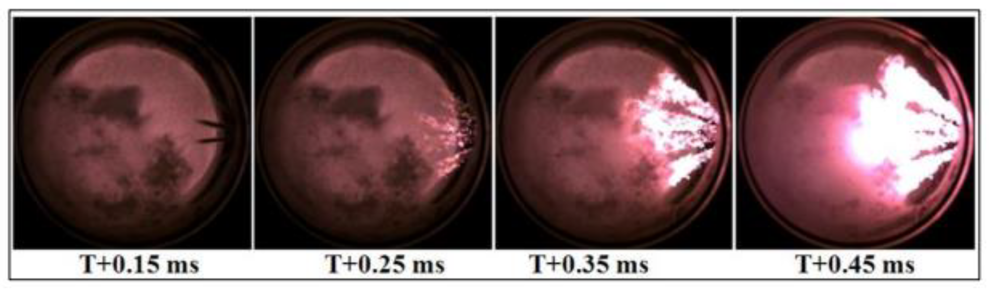
Figure 16.
The images presented in
Figure 16 were taken in the stationary environment in the following conditions: the injection pressure 1000 bar, the counterpressure in the transparent chamber 23 bar, the temperature of the environment in which the injection took place 800 °C, and the injection duration 0.23 ms. In
Figure 17, the ignition and the displacement of the flame front process in the following conditions are presented: the injection in a swirl environment with the rotational speed 6000 rpm, the injection pressure 1500 bar, the counterpressure in the transparent chamber 20 bar, and the injection duration 0.5 ms.
The combustion chamber 2, designed with a more complex form, named “butterfly”, has the same volume of 60 cm3, maintaining the same engine compression ratio. The constructive–functional optimization was made in the virtual environment using the Fluent program. The modified input data were the injection pressure, the counterpressure, the state of the environment in which the injection took place (stationary or with various rotational speeds of the swirl), the temperature of the injection’s environment, the diameter of the nozzle’s pulverization orifices, and their orientation. The model to be analyzed was calibrated by using the experimental data obtained through the visualization of the injection and the mixture formation processes inside the transparent chambers.
The optimization criterion for the burning chamber 2 was the variation in the specific fuel consumption values depending on the NO
x emissions, at various values of the swirl rotational speeds. In
Figure 18, the combustion chamber 2 geometry (butterfly shape) is presented, the realization of the butterfly shape being made in the exhaust piston. The evolution of the chamber’s optimization criterion values in a virtual environment is also presented, observing that the indicated specific fuel consumption depending on the indicated NO
x emission is most favorable for a swirl movement with the swirl number 2 (the rotational speed of the injection environment is two times bigger than the engine’s rotational speed). The swirl number represents the ratio between the air rotational speed and the engine’s rotational speed. The research was conducted at various air rotational speeds. For this optimal situation, in
Figure 18, the development in time of the injection process, the initialization of the combustion, and the evolution of the flame front are also presented.
The practically realized combustion chamber 2 was mounted on the EM100D engine, through which tests on the bench were carried out, according to the testing cycle US-13 Mode HD test points, as presented in
Figure 9. The architecture of the combustion chamber 3 was designed in such way as to use the swirl movement in the pulverization of the fuel jet and in the occupation of the entire space inside the combustion chamber with pulverized fuel. From previous research, the existence of some difficulties in the occupation of the combustion chamber’s center by the injected fuel were observed. As a result, in the construction of the combustion chamber 3 (toroidal shape), the existence of a central “dome” was chosen that has the role of dislocating the volume from the center of the chamber and contributing to the generation of a “tumble” movement of the air inside the burning chamber. Therefore, the shape of the combustion chamber 3 was designed in the form of torus, the fuel jets being injected in the direction of the swirl movement.
In
Figure 19, the geometry of the torus shape chamber is presented, observing that, this time, the shape of the burning chamber was machined both in the head of the intake piston and in the head of the exhaust piston. The mechanical processing of a part of the intake piston does not have a major influence on the scavenging process because the central dome occupies a relatively small part of the combustion chamber. The shape of the surface at the periphery of the combustion chamber remained suitable for the entrance of the fresh air into the cylinder. The volume of the combustion chamber 3 was also maintained at 60 cm
3, to keep the engine’s compression ratio.
The same as in the combustion chamber 2, the optimization criterion for the burning chamber 3 was the dependence between the value of the fuel specific consumption and the NO
x emission, at various values of the swirl rotational speed. This dependence is also presented in
Figure 19. It can be observed that the most favorable dependence between the fuel specific indicated consumption “c
i” and the NO
x emissions is realized when the value of the swirl movement coefficient is five, much greater than in the case of the combustion chamber 2. Additionally, in
Figure 19, the development of the injection process in time, the combustion initialization, and the combustion evolution for the situation in which the swirl coefficient is four are presented, considering that a greater value of the swirl will affect the gas exchange process.
After the simulation, an improvement in this combustion chamber’s performances regarding the performance criterion was observed, compared to the combustion chamber 2. This led to the practical realization of this chamber and its testing on the EM100D engine, also according to testing cycle US-13 Mode HD test points.
4. Discussion
The synthesis of the energetic and of the ecological parameters for the three constructive solutions of the combustion chambers, identified in the standardized test points, is presented in
Figure 29,
Figure 30 and
Figure 31.
The values of the energetic and ecological parameters determined for the three combustion chambers are synthetically presented in
Table 4.
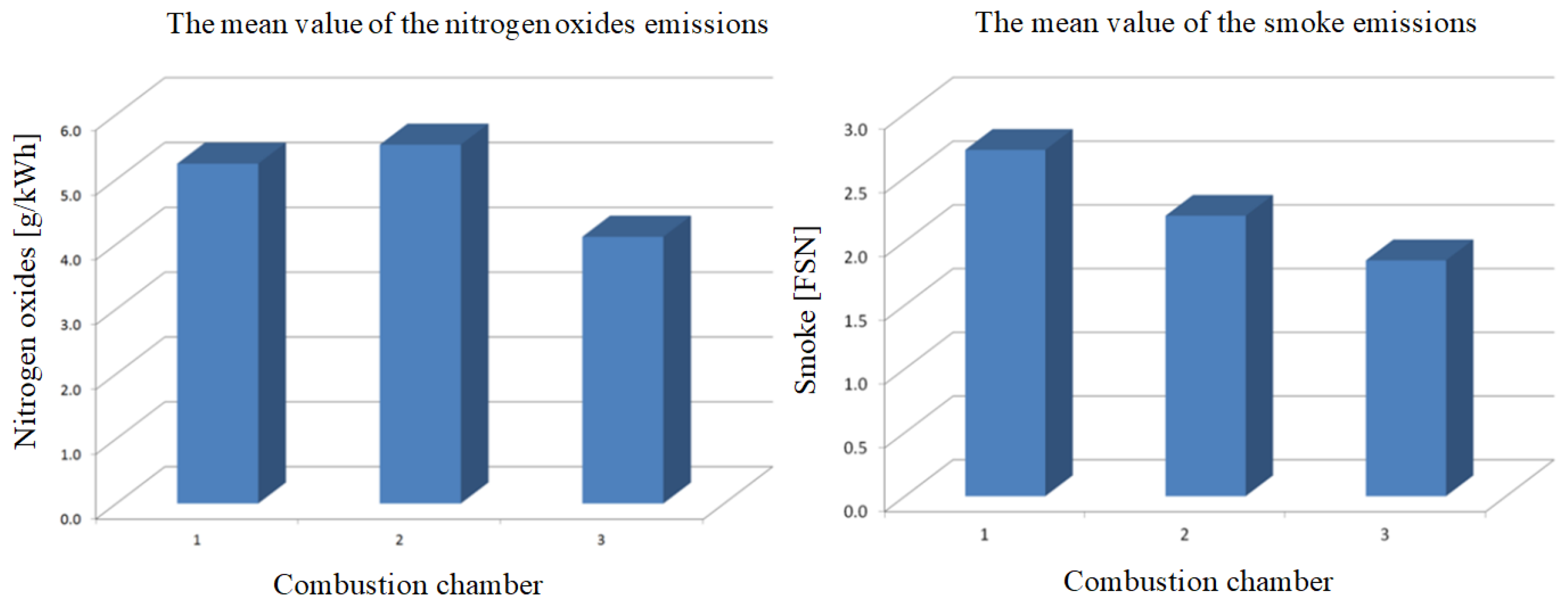
For the three combustion chambers experimentally studied, the results show that a toroid form combustion chamber ensures a superior behavior of the engine, in energetic and ecological aspects, with the specific fuel consumption being reduced by 11.5% compared to the combustion chamber 1 and by 9% compared to the combustion chamber 2. The nitrogen oxides emissions are reduced by 27% compared to the combustion chamber 1 and by 34% compared to the combustion chamber 2. The smoke emission is reduced by 47% compared to the combustion chamber 1 and by 19% compared to the combustion chamber 2. As a result of this study, a significant improvement in the engine’s ecological parameters obtained by modifying the shape of the combustion chamber manufactured in the piston bowls can be observed.
In
Figure 32, the comparison of the specific fuel consumption between the three variants is presented.
From
Figure 32, the results show that that fuel consumption in the case of chamber 3 (toroidal shape) was reduced by up to 12.5% compared with the chamber 1 (ovoid shape) and up to 8% compared with the chamber 2 (butterfly shape).
In
Figure 33, the comparison between the mean nitrogen oxides and smoke emissions for the three combustion chambers is presented.
For the combustion chamber 1, from
Figure 29 and
Table 4, it is found that the NO
x emission has a maximum value of 8.5 g/kWh in the point C100 from
Figure 5, corresponding to a rotational speed of 3000 rpm and an engine power of 179 kW. The maximum value of the smoke emission reaches its peak at 4.4, also in the point C100. The minimum fuel specific consumption of 233 g/kWh is registered in the point A75, shown in
Figure 5, corresponding to a rotational speed of 3000 rpm and an engine power of 108 kW. In these conditions, it was appreciated that the functioning of the EM100D engine is unsatisfactory, so the research was moved to develop another combustion chamber, according to the scheme presented in
Figure 6.
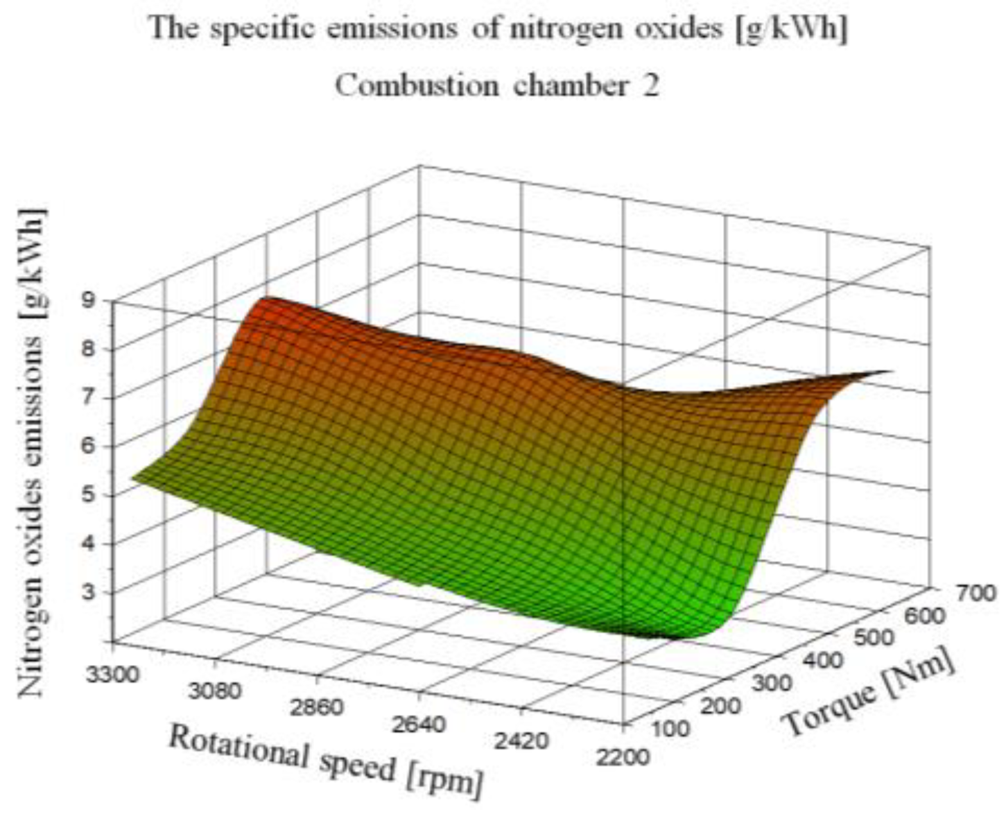
For the combustion chamber 2, from
Figure 30 and
Table 4, it is found that the NO
x emission has a maximum value of 7.7 g/kWh in the point C100 from
Figure 5, corresponding to a rotational speed of 3000 rpm and an engine power of 179 kW. The maximum value of the smoke emission reaches its peak at 4.4, also in the point C100. The minimum fuel specific consumption of 233 g/kWh is registered in the point A75, shown in
Figure 5, corresponding to a rotational speed of 3000 rpm and an engine power of 108 kW. In these conditions, it was appreciated that functioning of the EM100D is also unsatisfactory, so the research was moved to develop another combustion chamber, according to the scheme presented in
Figure 6.
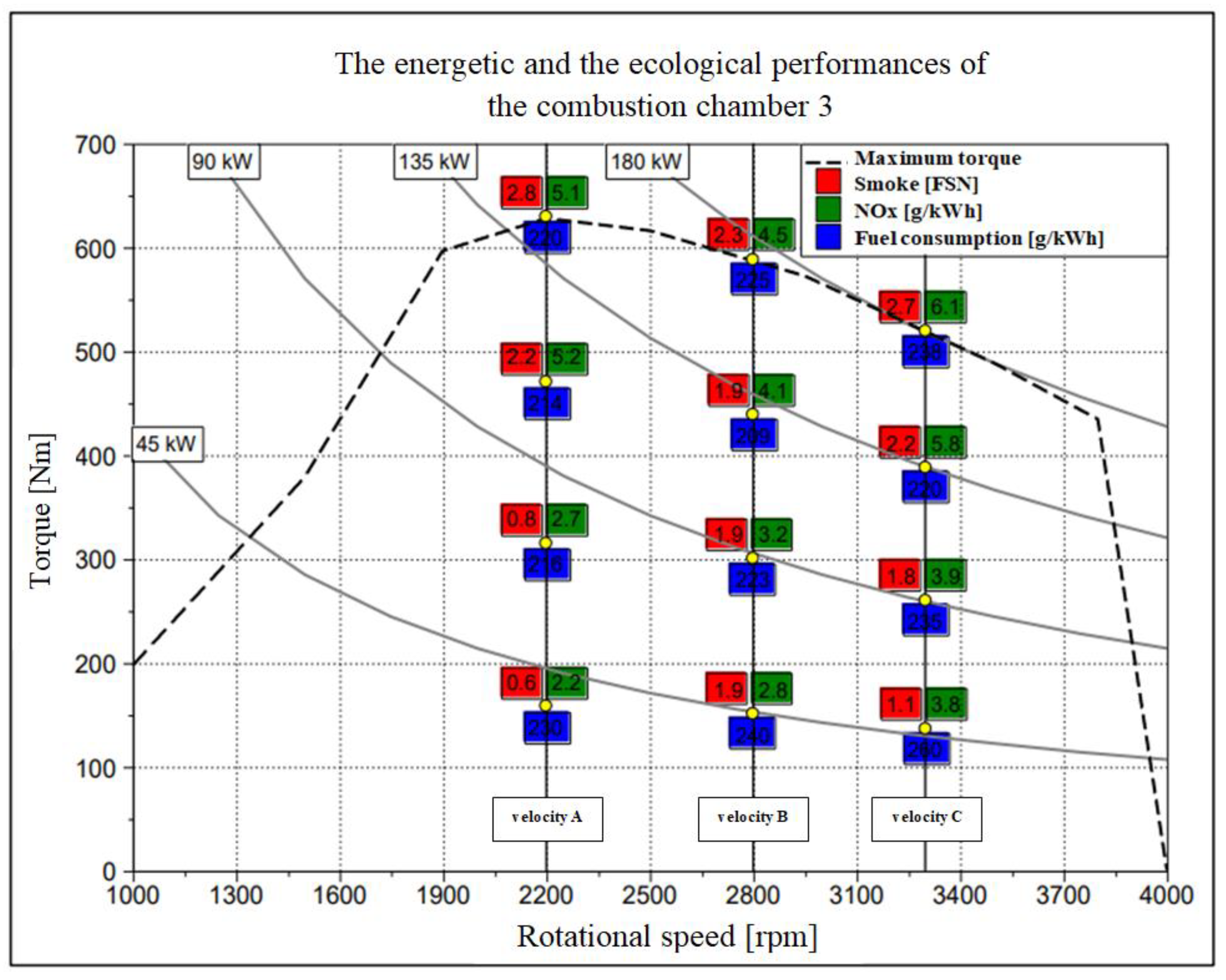
For the combustion chamber 3, from
Figure 31 and
Table 4, it was found that the nitrogen emission has a maximum value of 6.1 g/kWh in the point C100, the smoke emission reaches 2.8 FSN in the point A100, corresponding to a rotational speed of 2200 rpm and a power of 144 kW, and the minimum fuel consumption is 209 g/kWh in the point B75, corresponding to a rotational speed of 2800 rpm and a power of 129 kW.
From
Table 4, it can be observed that the minimum values of the nitrogen oxides and smoke emissions are registered in the point A25, corresponding to a rotational speed of 2200 rpm and a power of 36 kW.
However, these results were not considered totally satisfactory, because the combustion chamber 3 does not totally fulfil, at the level of maximum demands, the conditions imposed by the initial target values.
The testing showed that usually, for an opposed piston engine, more than one injector per cylinder is required. This is imposed by the larger volume per cylinder, by the desire to have a reasonably small diameter of the nozzle’s holes, and by the difficulty of placing a larger number of holes in the nozzle. To prevent the collision with the sprays generated by the other injector, the penetration of the fuel sprays must be short enough. It is recommended to use smaller hole diameters, since the jets’ penetration and atomization strongly depend on this parameter. The duration of the fuel injection has a significant influence on the sprays’ atomization and penetration, so more injection events will be beneficial. The fuel sprays can occupy the entire space of the combustion chamber even if there is no air motion inside the cylinder. For a good scavenging, the architecture of the combustion chamber must reduce the velocity of the rotational air movement and enhance local turbulence instead. A higher level of swirl will negatively affect the mixture formation.
During the research, it was observed that in the case of the combustion chamber 1 (ovoid shape) and of the combustion chamber 2 (“butterfly” shape), the sprays are affected, and the fuel does not reach the center of the cylinder. This is why the combustion chamber 3 (toroidal shape) was realized. It was observed that in this case, the combustion chamber was fully occupied by the fuel. Therefore, the energetic and the ecological performances for the combustion chamber 3 are much improved compared with the other variants. The results of this research can be used for the further development of the OPOC engine. The mathematical model developed in this research was calibrated by using the results of the experiment. This calibrated model can be used for a further improvement of the engine’s performances, reducing the time and the costs compared to experimental research.
Therefore, the research continued. As a result, a new engine with smaller dimensions was designed and realized. This will be subject of another scientific paper. Another research direction will be the improvement of the EM100D engine’s performances in the case of using Diesel fuel. For this, the use of two injectors in the cylinder is necessary. It is important that the jets should not intersect, which is why it is important to adopt the multiple injections technique. It is possible to adopt the variant with fuel injection pressure over 2500 bar with multiple injections. which should ensure a limited penetration of the jets and a corresponding atomization. EGR techniques can be adopted to reduce the nitrogen oxides emissions. Within a project entitled “Water recovery system from vehicle’s combustion engine exhaust gas”, research was carried to recover the water vapors from the exhaust gases. This was a Cheques of Innovation project, and the project’s code was PN-III-P2-2.1-CI-2018-1566. An important technique to reduce nitrogen oxides emissions is to lower the maximum temperature inside the cylinder. This can be realized by the injection of the recovered water in order to temper the maximum temperature of the engine cycle, so the nitrogen emissions should be diminished. Another research subject will be the use of gaseous fuels, such as methane and hydrogen, or of synthetic fuels.
This internal combustion engine with opposed pistons can be used in hybrid electric vehicles (HEV). As shown above, the minimum pollutant emissions of the EM100D engine are registered at low and medium loads, but the specific fuel consumption is higher. An internal combustion engine used in HEV has the advantage that it functions in a single regime, so its control is simpler. The functioning regime must be chosen in such a way as to achieve a compromise between the value of the fuel consumption and the level of the pollutant emissions.


