
Effect of Slot Jet Flow on Non-Axisymmetric Endwall Cooling Performance of High-Load Turbines

 ,
,  ,
,
Abstract
:1. Introduction
2. Computational Method and Validation
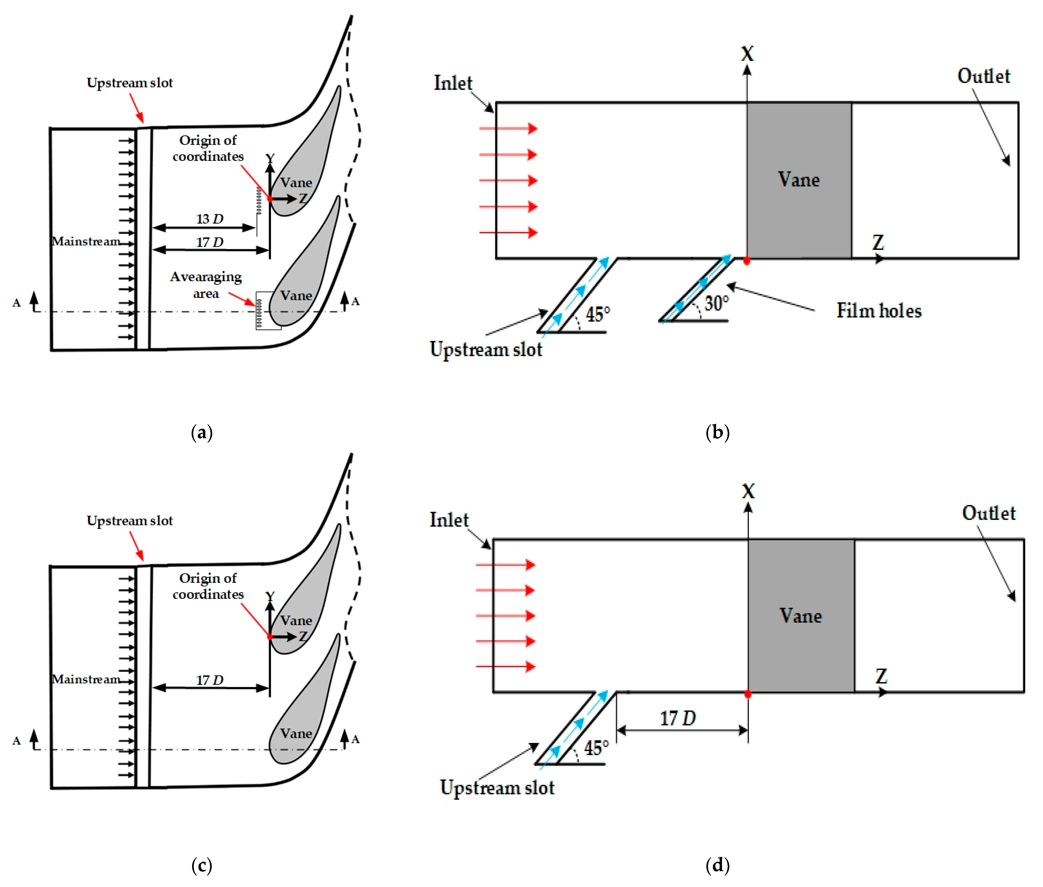
2.1. Geometrical Model
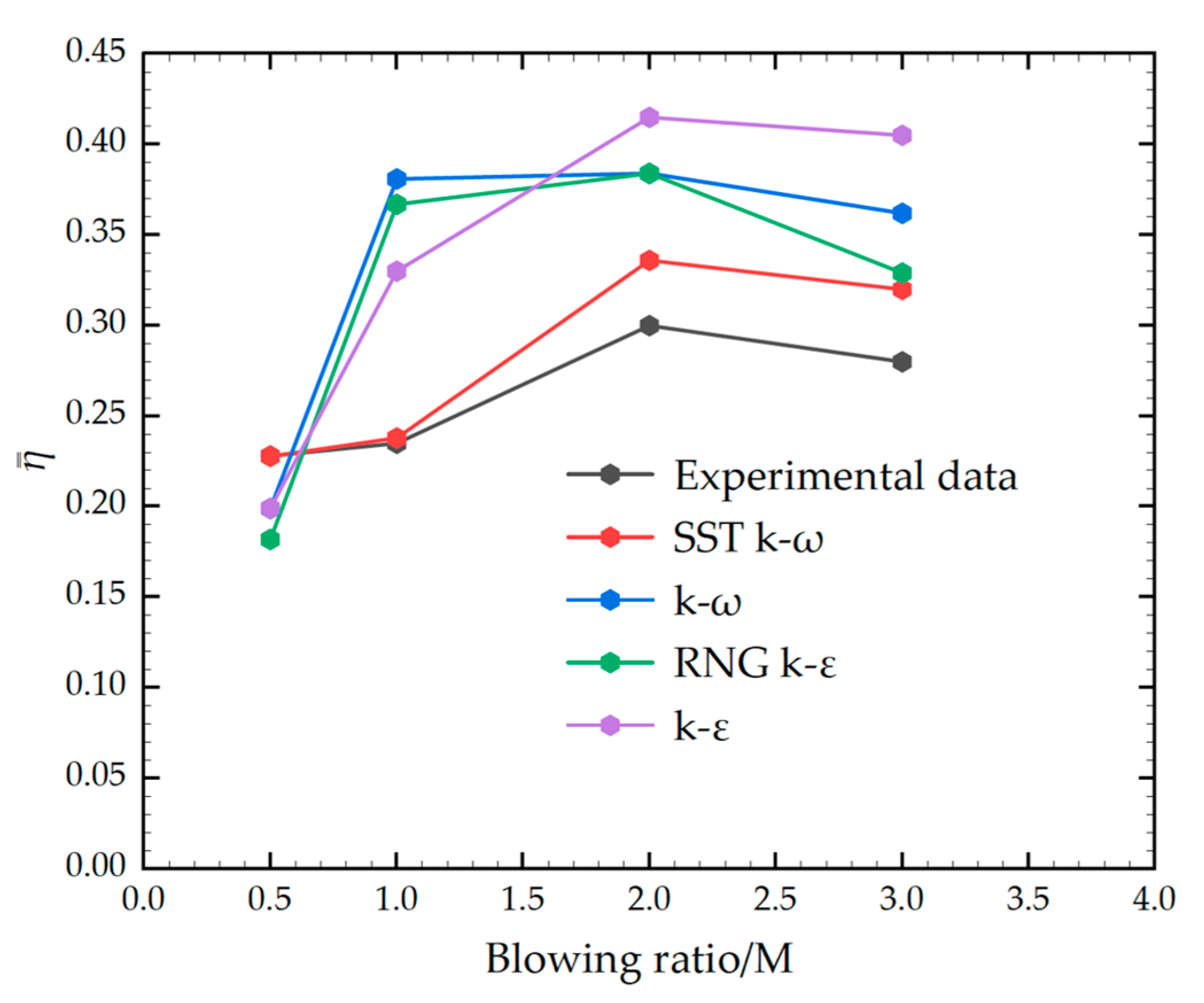
2.2. Turbulence Model Validation and Boundary Conditions
2.3. Mesh Independence Verification
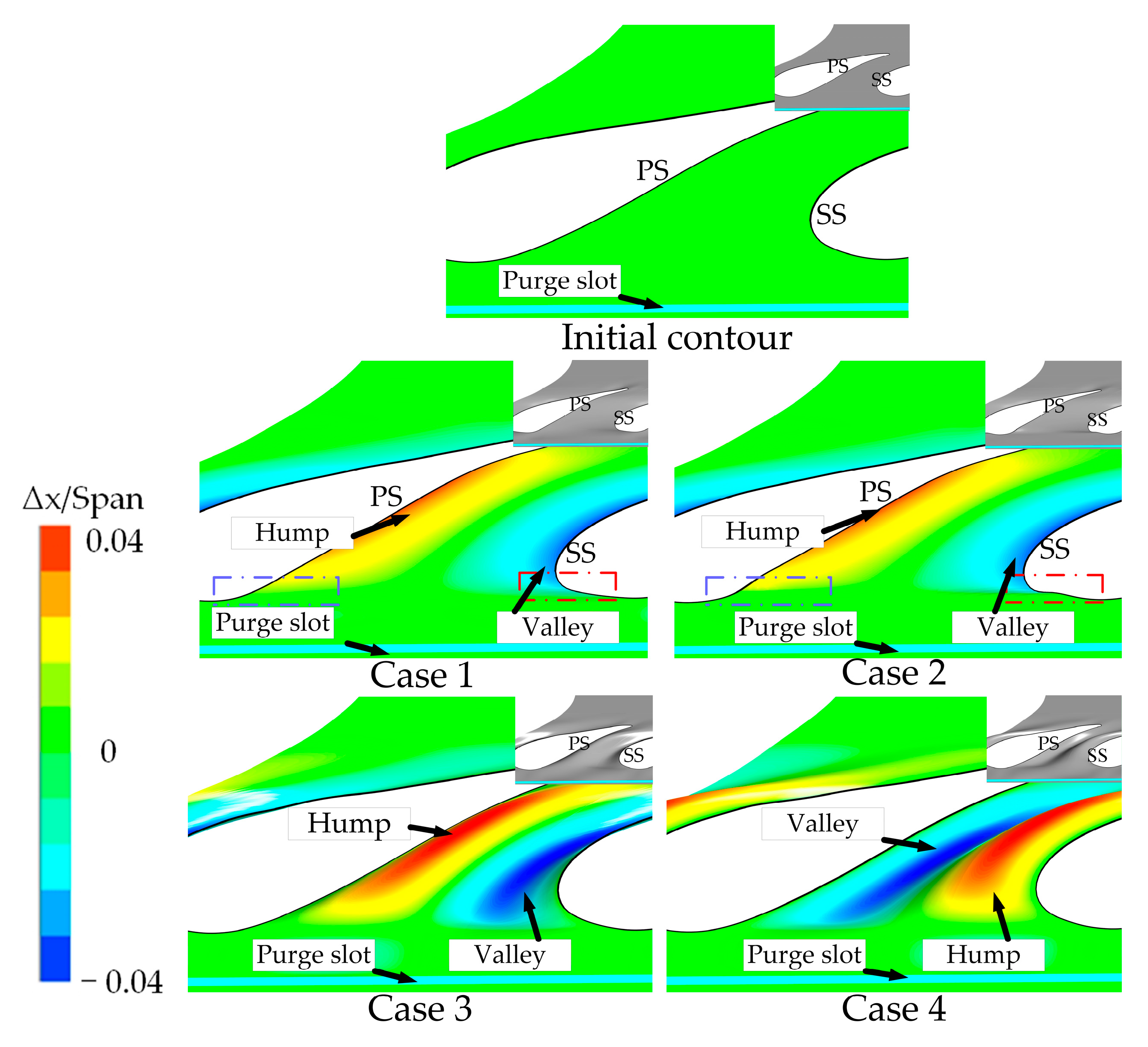
2.4. Non-Axisymmetric Endwall (NEC) Design
- (1)
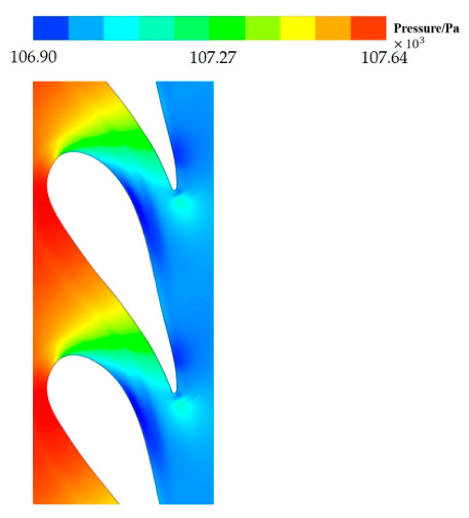
- The static pressure distribution of the flat endwall for a non-purge flow is obtained numerically(as shown in Figure 3);
- (2)
- Axial control function;
- (3)
- Half-cycle circumferential function;
- (4)
- Full cycle circumferential control function:
3. Results
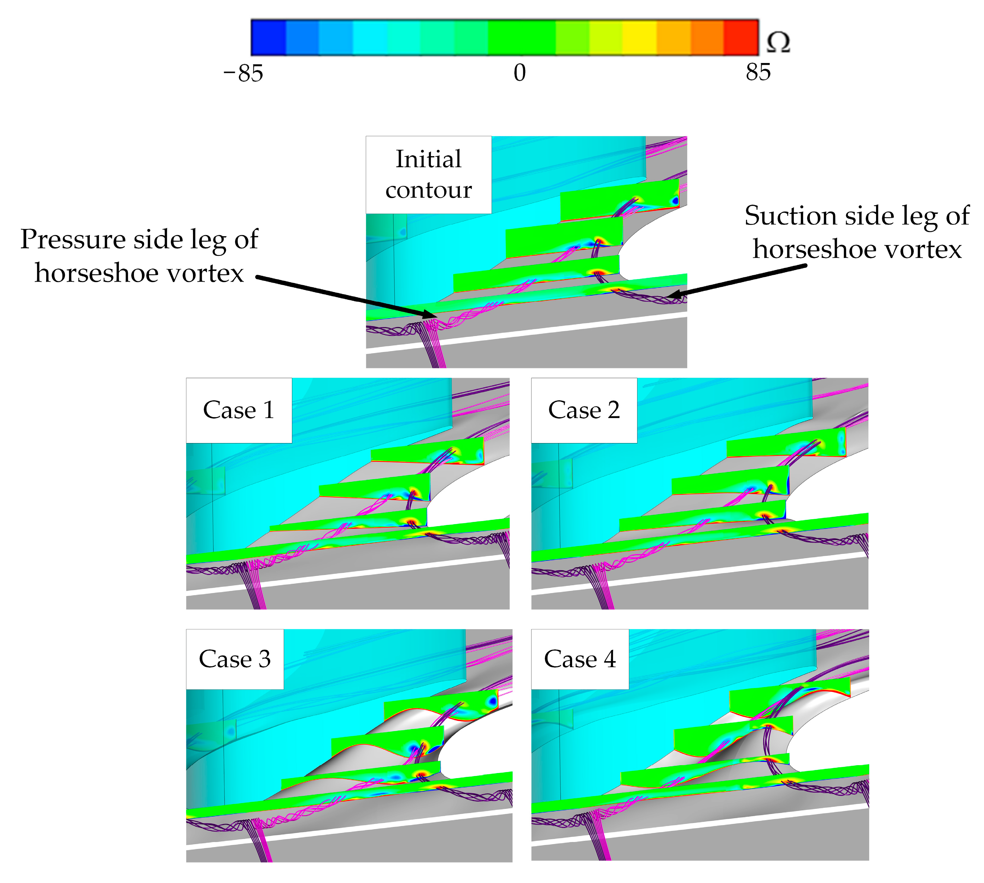
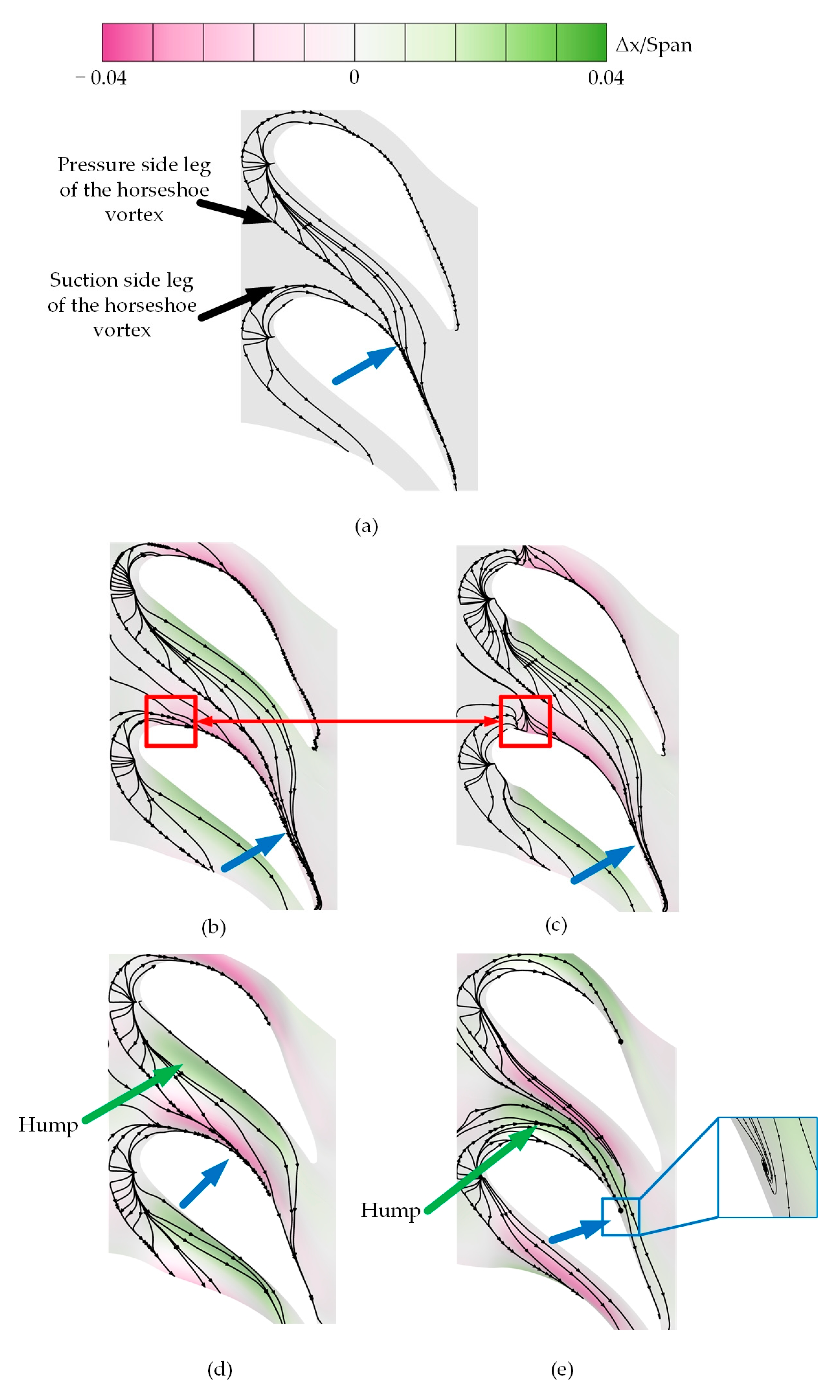
3.1. Flow Field and Aerodynamic Analysis
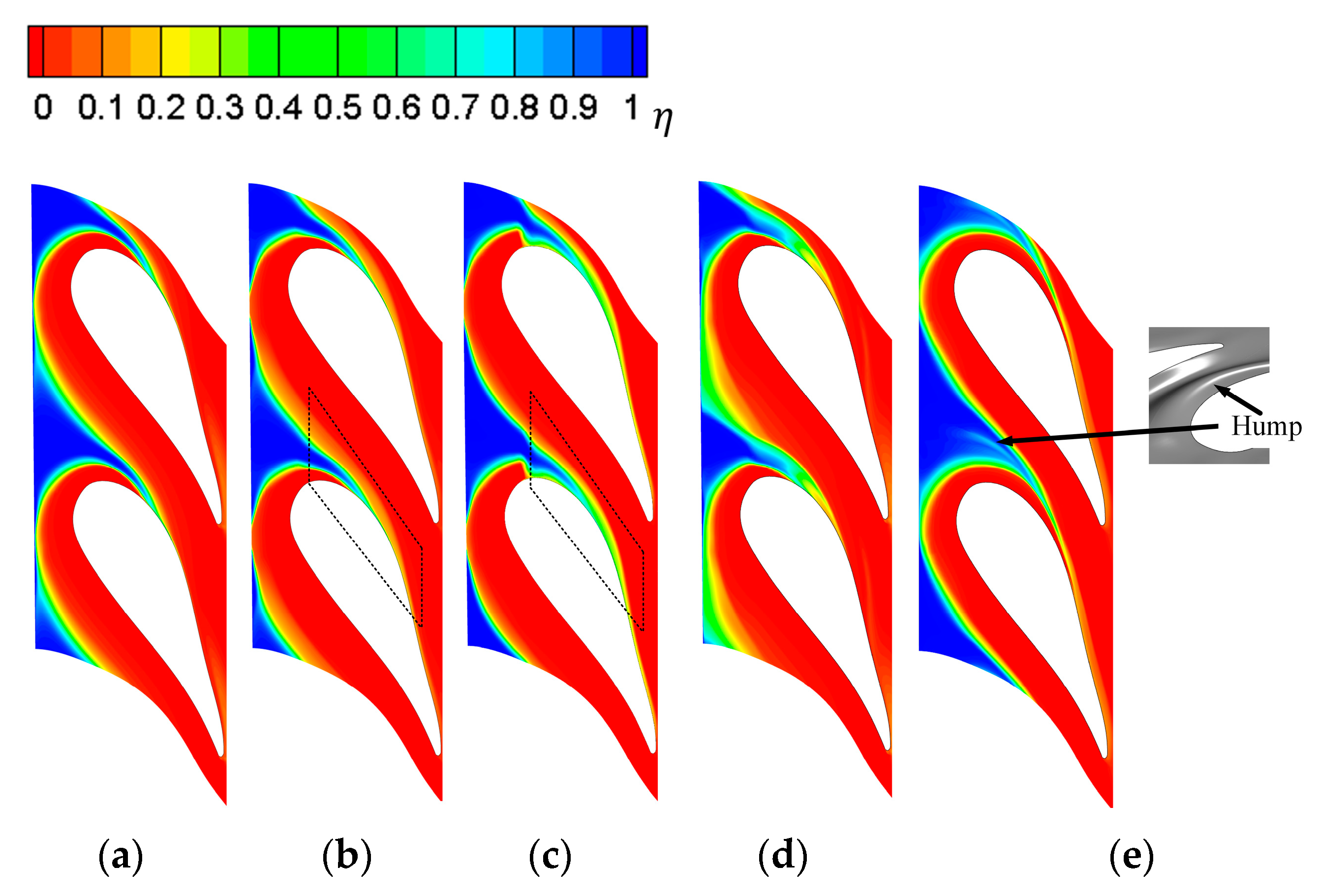
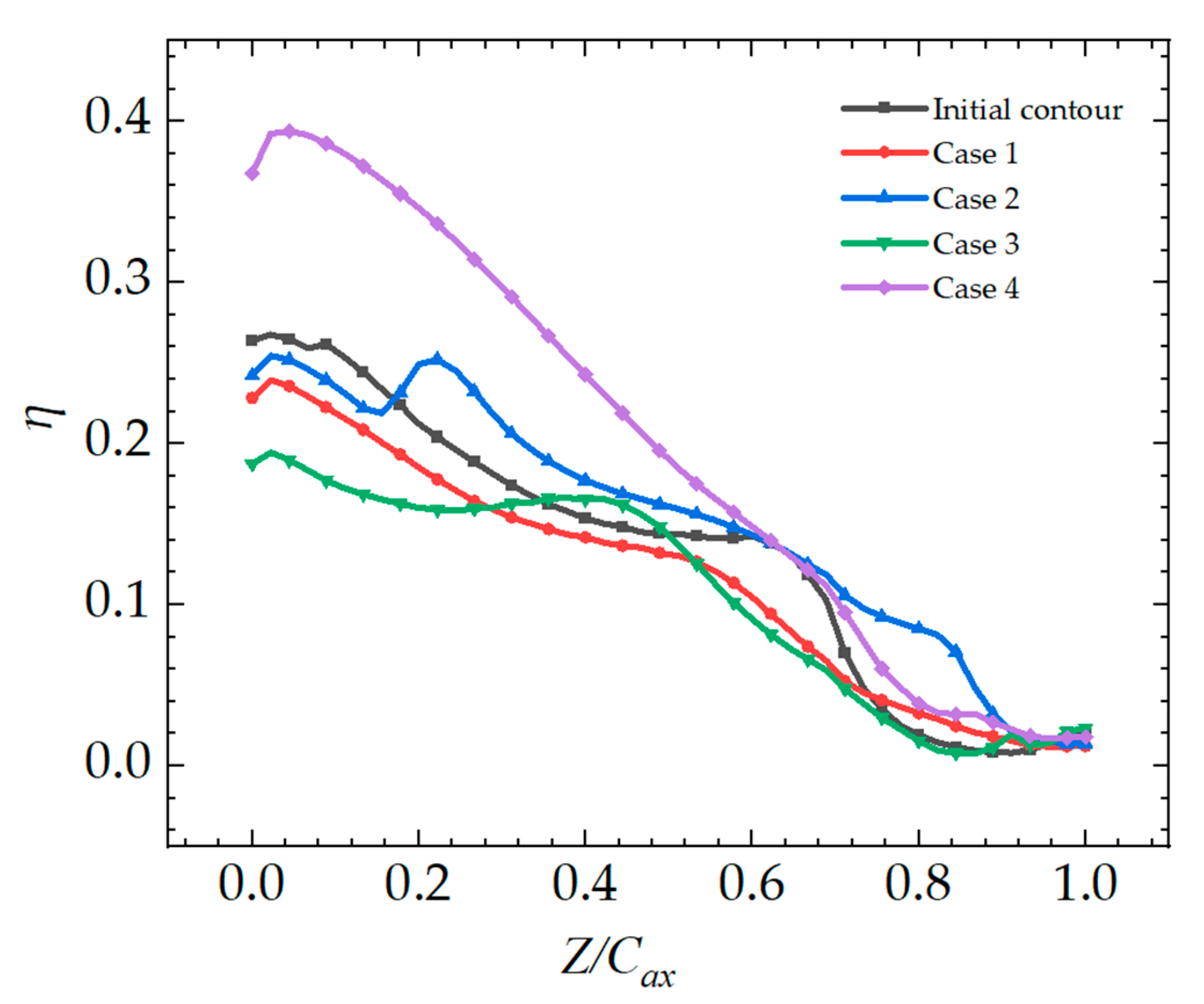
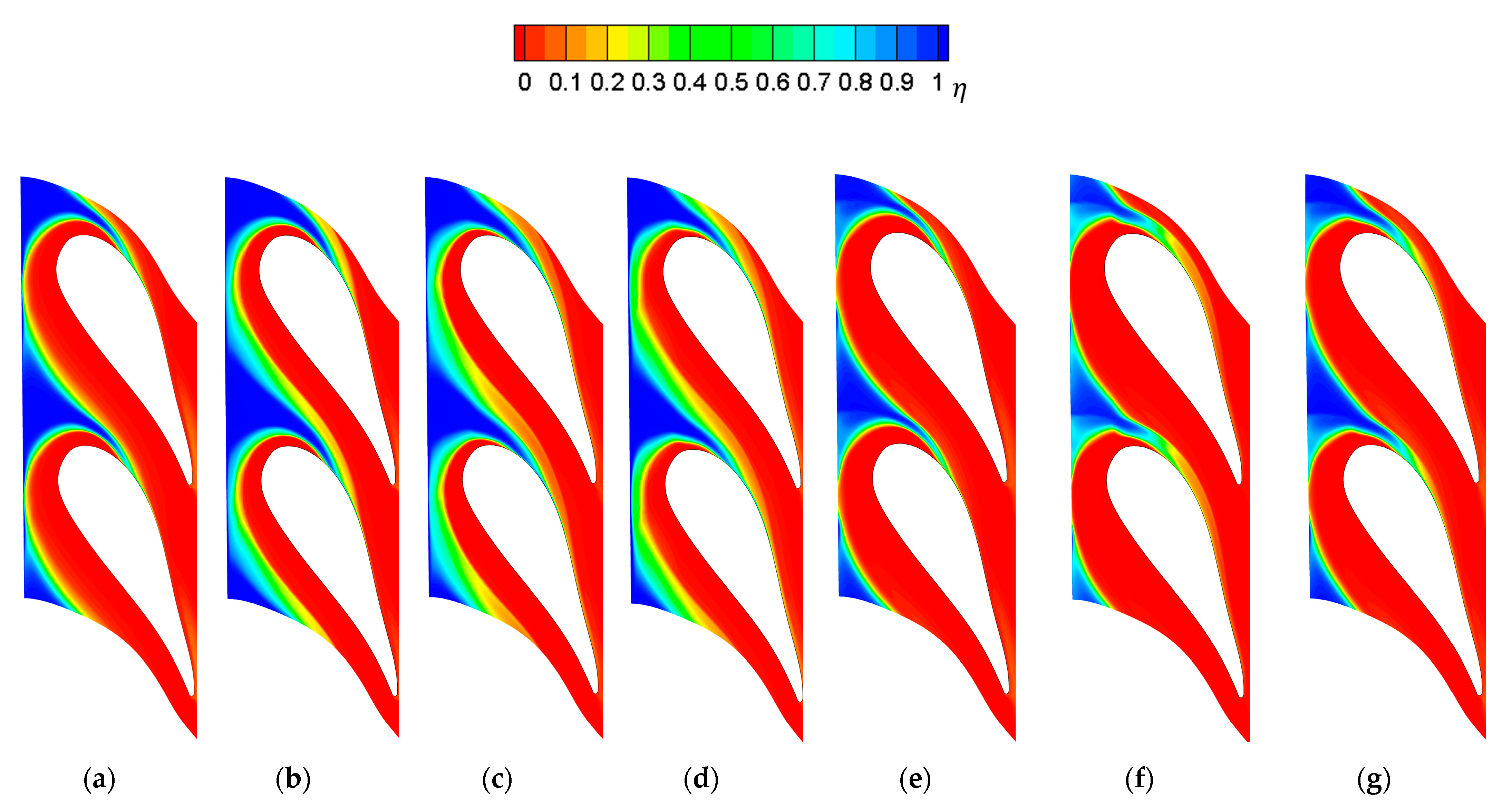
3.2. Film Cooling Performance Analysis
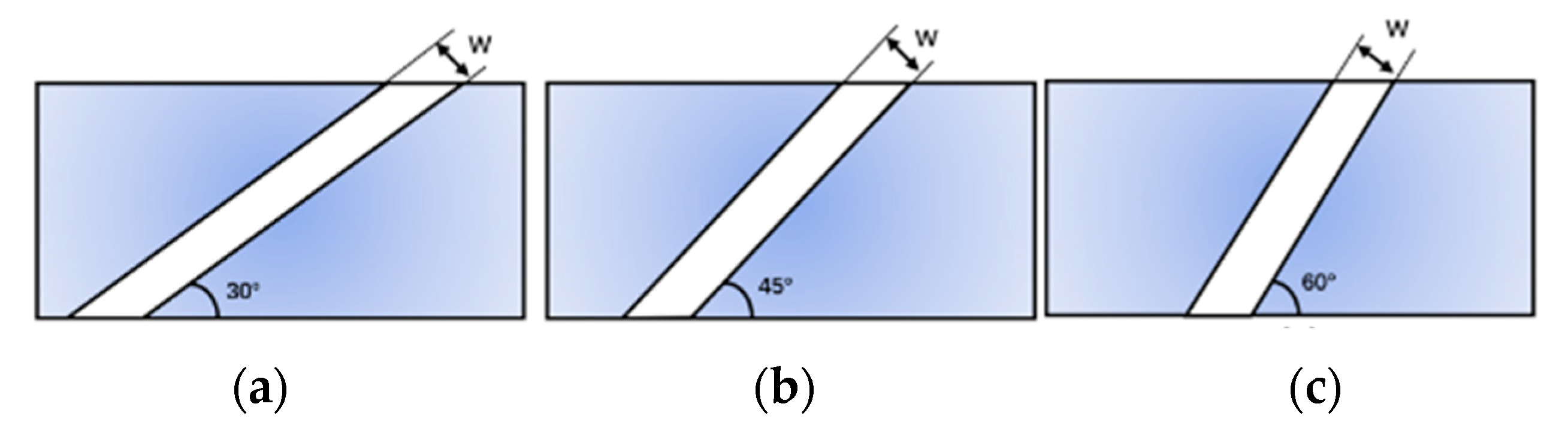
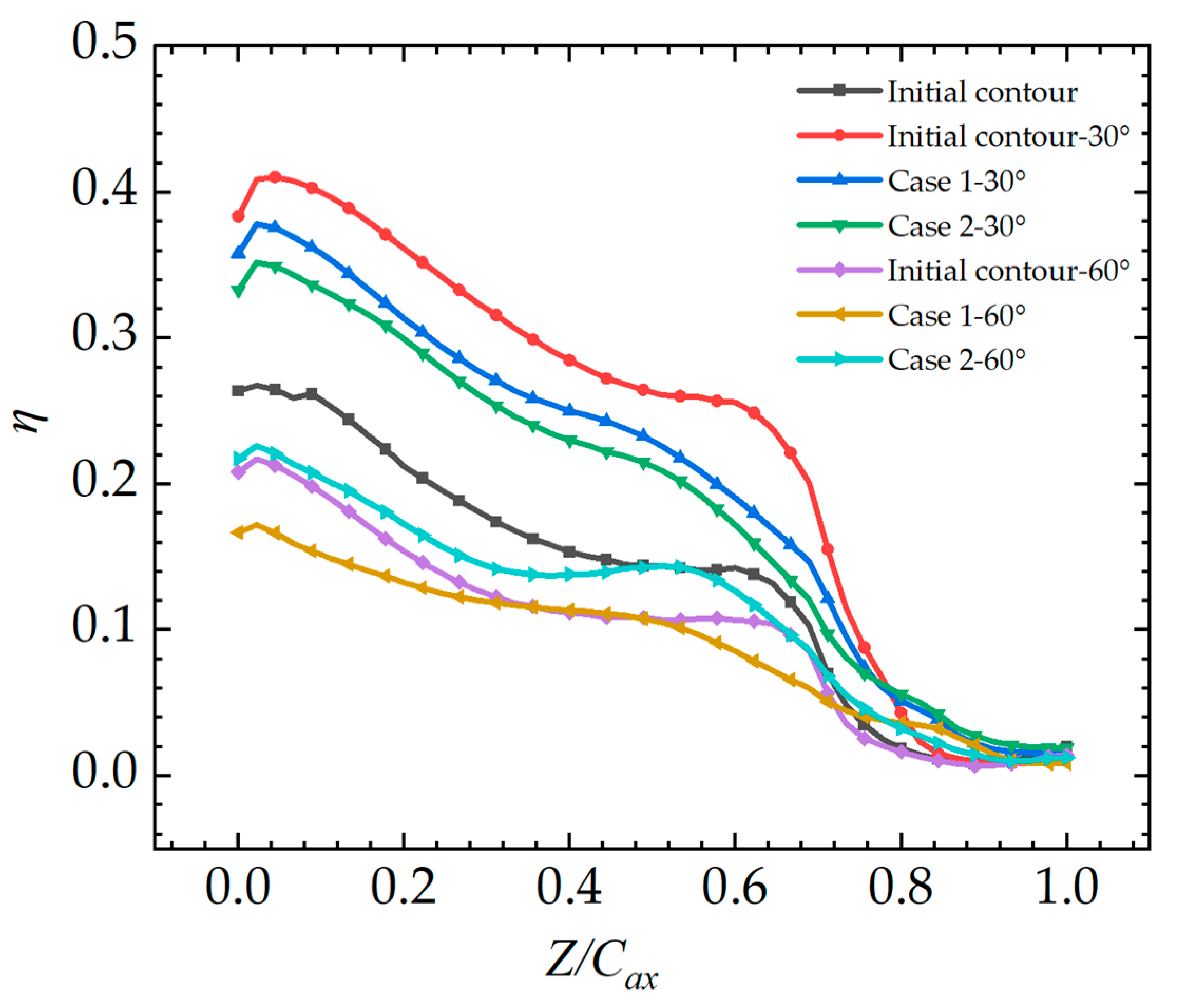
3.3. Effect of Slotting Angle on Gas Film Cooling Characteristics of Molded Endwall
4. Conclusions
- (1)
- For the computational model of the study, the NEC based on differential pressure contouring can decrease the aerodynamic losses in the cascade by reducing the lateral pressure differences. Case 3 has the best aerodynamic characteristic, and the total pressure loss coefficient of the cascade is reduced by 0.305%.
- (2)
- The NEC can significantly increase the coverage area for coolant, and Case 4 is up to 28.29% higher than the Initial contour. To balance the aerodynamic and cooling characteristics, Case 2 achieves the best outcome, with the total pressure loss coefficient of cascade being reduced by 0.272% and the non-dimensional effective coverage area of coolant increases by 11.74% compared to the baseline endwall.
- (3)
- Endwall molding can improve the protective effect of a jet with a large slot angle but has no obvious effect on a jet with a small angle. Compared to the Initial contour-60°, the coverage area of coolant is increased by 7.51% with Case 2-60°. In contrast, based on the Initial contour-30°, Case 2-30° slightly enhances the coverage area of coolant by 2.99%.
Author Contributions
Funding
Institutional Review Board Statement
Informed Consent Statement
Data Availability Statement
Conflicts of Interest
References
- Han, J.C. Advanced cooling in gas turbines 2016 max Jakob memorial award paper. J. Heat Transfer. 2018, 140, 113001. [Google Scholar] [CrossRef]
- Wang, W.; Yan, Y.; Zhou, Y.; Cui, J. Review of Advanced Effusive Cooling for Gas Turbine Blades. Energies 2022, 15, 8568. [Google Scholar] [CrossRef]
- Barigozzi, G.; Abdeh, H.; Rouina, S.; Franchina, N. The Aero-Thermal Performance of Purge Flow and Discrete Holes Film Cooling of Rotor Blade Platform in Modern High Pressure Gas Turbines: A Review. Int. J. Turbomach. Propuls. Power 2022, 7, 22. [Google Scholar] [CrossRef]
- Chen, P.T.; Wang, L.; Li, X.Y.; Ren, J.; Jiang, H.D. Effect of axial turbine non-axisymmetric endwall contouring on film cooling at different locations. Int. J. Heat Mass Transfer. 2020, 147, 118995. [Google Scholar] [CrossRef]
- Denton, J.D. Loss Mechanisms in Turbomachines. In Proceedings of the ASME 1993 International Gas Turbine and Aeroengine Congress and Exposition, Cincinnati, OH, USA, 24–27 May 1993. [Google Scholar]
- Rose, M.G. Non-axisymmetric end wall profiling in the HP NGVs of an axial flow gas turbine. In Proceedings of the ASME 1994 International Gas Turbine and Aeroengine Congress and Exposition, The Hague, Netherlands, 13–16 June 1994. [Google Scholar]
- Harvey, N.W.; Rose, M.G.; Taylor, M.D.; Shahpar, S.; Hartland, J.; Gregory-Smith, D.G. Non-axisymmetric Turbine End Wall Design: Part I-Three Dimensional Linear Design System. In Proceedings of the ASME 1999 International Gas Turbine and Aeroengine Congress and Exhibition, Indianapolis, IN, USA, 7–10 June 1999. [Google Scholar]
- Chen, P.T.; Zhao, K.; Li, X.Y.; Ren, J.; Jiang, H.D. Effects of varying non-axisymmetric contours of the turbine endwall on aerodynamics and heat transfer Aspects: A sensitivity analysis study. Int. J. Therm. Sci. 2021, 161, 106689. [Google Scholar] [CrossRef]
- Ahn, J. Large Eddy Simulation of Film Cooling: A Review. Energies 2022, 15, 8876. [Google Scholar] [CrossRef]
- Zhang, C.; Wang, W.; Wang, Z.; Tong, Z. Conjugate Heat Transfer Simulation of Overall Cooling Performance for Cratered Film Cooling Holes. Machines 2022, 10, 395. [Google Scholar] [CrossRef]
- Zhao, L.; Ma, H. Experimental Investigation of the Effect of Purge Flow and Main Flow Interaction in a Low-Speed Turbine Cascade Passage. Entropy 2020, 22, 623. [Google Scholar] [CrossRef] [PubMed]
- Sundaram, N.; Thole, K.A. Bump and Trench Modifications to Film Cooling Holes at the Vane-Endwall Junction. In Proceedings of the ASME Turbo Expo 2007: Power for Land, Sea, and Air, Montreal, Canada, 14–17 May 2007. [Google Scholar]
- Du, K.; Song, L.M.; Li, J.; Sunden, B. Effects of the mainstream turbulence intensity and slot injection angle on the endwall cooling and phantom cooling of the vane suction side surface. Int. J. Heat Mass Transfer. 2017, 112, 427–440. [Google Scholar] [CrossRef]
- Tao, Z.; Yao, Y.J.; Zhu, P.Y.; Song, L.M.; Li, J. Experimental and numerical study on film cooling effectiveness of an annular cascade endwall with different slot configuration. Int. J. Therm. Sci. 2020, 158, 106517. [Google Scholar] [CrossRef]
- Babu, S.; Kiran, K.N.; Tom, J.K.; Anish, S. Numerical Investigation on Effects of Profiled Endwall Over Purge Flow in Linear Turbine Cascade. In Proceedings of the 7th Asian Joint Workshop on Thermophysics and Fluid Science, Trivandrum, India, 24 November 2018. [Google Scholar]
- Zhang, K.Y.; Li, Z.G.; Li, J. Non-axisymmetric endwall contour optimization and performance assessment as affected by simulated swirl purge flow and backward hole injection. Int. J. Therm. Sci. 2022, 172, 107297. [Google Scholar] [CrossRef]
- Tao, Z.; Guo, Z.D.; Yu, B.Y.; Song, L.M.; Li, J. Aero-Thermal Optimization of a Gas Turbine Blade Endwall with Non-Axisymmetric Contouring and Purge Flow. Int. J. Heat Mass Transfer. 2021, 178, 121626. [Google Scholar] [CrossRef]
- Mensch, A.; Thole, K.A. Overall Effectiveness and Flowfield Measurements for an Endwall with Non-axisymmetric Contouring. In Proceedings of the ASME Turbo Expo 2015: Turbine Technical Conference and Exposition, Montreal, QC, Canada, 15–19 June 2015. [Google Scholar]
- Du, K.; Li, J. Numerical study on the effects of slot injection configuration and endwall alignment mode on the film cooling performance of vane endwall. Int. J. Heat Mass Transfer. 2016, 98, 768–777. [Google Scholar] [CrossRef]


| Parameters | Value |
|---|---|
| Chord length of blade C | 594 mm |
| Axial chord of blade Cax | 293 mm |
| Pitch, P/C | 0.77 |
| Span/Chord, S/C | 0.93 |
| Upstream slot width | 0.024 C |
| Hole, L/D | 8.3 |
| Inlet and exit angles | 0° & 72° |
| Hole diameter D | 4.6 mm |
| Parameters | Value |
|---|---|
| Mainstream inlet total temperature | 333.19 K |
| Mainstream inlet total pressure | 107.64 kPa |
| Coolant inlet total temperature | 293.15 K |
| Rein | 2.1 × 10⁵ |
| Inlet Ma | 0.017 |
| Inlet turbulence intensity | 1% |
| Outlet Ma | 0.085 |
| Outlet static pressure | 107 kPa |
| Flow ratio(coolant/mainstream) | 0.6% |
| Grid Numbers | |
|---|---|
| 3 × 10⁶ | 0.0652 |
| 4 × 10⁶ | 0.0655 |
| 5 × 10⁶ | 0.0658 |
| 6 × 10⁶ | 0.0659 |
| Case | |
|---|---|
| Case 1 | 0.114 |
| Case 2 | 0.272 |
| Case 3 | 0.305 |
| Case 4 | −1.800 |
| Case | |
|---|---|
| Case 1 | 8.41 |
| Case 2 | 11.74 |
| Case 3 | −4.13 |
| Case 4 | 28.29 |
| Case | |
|---|---|
| Initial contour-30° | 33.99 |
| Case 1-30° | 36.18 |
| Case 2-30° | 36.98 |
| Initial contour-60° | −27.22 |
| Case 1-60° | −22.55 |
| Case 2-60° | −19.71 |
Disclaimer/Publisher’s Note: The statements, opinions and data contained in all publications are solely those of the individual author(s) and contributor(s) and not of MDPI and/or the editor(s). MDPI and/or the editor(s) disclaim responsibility for any injury to people or property resulting from any ideas, methods, instructions or products referred to in the content. |
© 2023 by the authors. Licensee MDPI, Basel, Switzerland. This article is an open access article distributed under the terms and conditions of the Creative Commons Attribution (CC BY) license (https://creativecommons.org/licenses/by/4.0/).
Share and Cite
Du, K.; Jia, Y.; Song, H.; Chen, L.; Zhang, Q.; Cui, T.; Liu, C. Effect of Slot Jet Flow on Non-Axisymmetric Endwall Cooling Performance of High-Load Turbines. Machines 2023, 11, 134. https://doi.org/10.3390/machines11020134
Du K, Jia Y, Song H, Chen L, Zhang Q, Cui T, Liu C. Effect of Slot Jet Flow on Non-Axisymmetric Endwall Cooling Performance of High-Load Turbines. Machines. 2023; 11(2):134. https://doi.org/10.3390/machines11020134
Chicago/Turabian StyleDu, Kun, Yihao Jia, Hui Song, Lei Chen, Qian Zhang, Tingting Cui, and Cunliang Liu. 2023. "Effect of Slot Jet Flow on Non-Axisymmetric Endwall Cooling Performance of High-Load Turbines" Machines 11, no. 2: 134. https://doi.org/10.3390/machines11020134
APA StyleDu, K., Jia, Y., Song, H., Chen, L., Zhang, Q., Cui, T., & Liu, C. (2023). Effect of Slot Jet Flow on Non-Axisymmetric Endwall Cooling Performance of High-Load Turbines. Machines, 11(2), 134. https://doi.org/10.3390/machines11020134