Article

Research on a Method of Robot Grinding Force Tracking and Compensation Based on Deep Genetic Algorithm

College of Mechanical and Power Engineering, Chongqing University of Science and Technology, Chongqing 401331, China
*
Author to whom correspondence should be addressed.
Machines 2023, 11(12), 1075; https://doi.org/10.3390/machines11121075
Submission received: 6 November 2023 / Revised: 5 December 2023 / Accepted: 5 December 2023 / Published: 8 December 2023
(This article belongs to the Topic Robotic Intelligent Machining System)

Abstract

:
In the grinding process of complex-shaped cast workpieces, discrepancies between the workpiece’s contours and their corresponding three-dimensional models frequently lead to deviations in the machining trajectory, resulting in instances of under-grinding or over-grinding. Addressing this challenge, this study introduces an advanced robotic grinding force automatic tracking technique, leveraging a combination of deep neural networks and genetic algorithms. Harnessing the capability of force sensing, our method dynamically recalibrates the grinding path, epitomizing truly flexible grinding. Initially, in line with the prerequisites for force and pose tracking, an impedance control strategy was developed, integrating pose deviations with force dynamics. Subsequently, to enhance steady-state force tracking, we employed a genetic algorithm to compensate for force discrepancies caused by positional errors. This was built upon the foundational concepts of the three-dimensional model, impedance control, and environmental parameter estimation, leading to an optimized grinding trajectory. Following tracking tests, it was observed that the grinding’s normal force was consistently controlled within the bracket of 20 ± 2.5 N. To further substantiate our methodology, a specialized experimental platform was established for grinding complex-shaped castings. Optimized strategies were employed under anticipated forces of 5 N, 10 N, and 15 N for the grinding tests. The results indicated that the contact forces during the grinding process remained stable at 5 ± 1 N, 10 ± 1.5 N, and 15 ± 2 N. When juxtaposed with conventional teaching grinding methods, our approach manifested a reduction in grinding forces by 71.4%, 70%, and 75%, respectively. Post-grinding, the workpieces presented a pronounced enhancement in surface texture, exhibiting a marked increase in surface uniformity. Surface roughness metrics, originally recorded at 17.5 μm, 17.1 μm, and 18.7 μm, saw significant reductions to 1.5 μm, 1.6 μm, and 1.4 μm, respectively, indicating reductions by 76%, 73%, and 78%. Such outcomes not only meet the surface finishing standards for complex-shaped castings but also offer an efficacious strategy for robot-assisted flexible grinding.

1. Introduction

With the advancement of the industrial economy and intelligent manufacturing processes, the utilization of various small-batch, irregularly shaped surface workpieces in fields such as special equipment and fluid machinery is becoming increasingly widespread. Due to the intricate structures and diverse materials of non-uniformly curved workpieces, many market applications still rely on manual grinding for tasks like deburring and post-processing. The working conditions on-site are challenging, with high labor intensity, and the generation of metal dust during grinding poses health risks to the workers. This mode of operation is notably inefficient, resulting in varying product quality and high production costs, which significantly impact enterprise development. In the context of rapid industrial automation growth, the use of robots across various sectors is expanding [1,2]. In the manufacturing industry, robot polishing technology plays a very important role; it can greatly improve the production efficiency of products and ensure the production quality of products [3]. However, maintaining precise force control during robotic grinding presents a significant challenge, particularly when dealing with complex-shaped workpieces. This challenge stems from their intricate contours, deviations from 3D models, and the inherent contact nature of workpiece grinding. Even slight tool displacement can lead to a rapid increase in deviational force or torque, thereby exacerbating grinding errors [4,5,6].
In recent years, scholars have undertaken research concerning grinding robots, with a primary focus on investigating critical factors [7], such as grinding force, tool feed rate, grinding depth, and material removal rate during grinding [8,9,10]. Notably, Calanca et al. [11] accomplished the desired force-tracking effect by utilizing an adaptive algorithm to adjust resistance model parameters in real time based on feedback force errors. Lee et al. [12] achieved contact force control of robots by actively modifying the stiffness of impedance models. Lin et al. [13] proposed a force-controlled end effector for the robot MRF process to maintain the stability of the polishing process. The team led by Haibo [14] developed a hybrid control approach for grinding and polishing robots that integrates adaptive impedance control technology. This approach employs active compliance technology to enhance the precision of the position and the performance of force control tracking. Mohammad Mehdi et al. [15] employed adaptive fuzzy control in robotic systems, leading to adaptive tracking control. Additionally, Sara et al. [16] utilized an adaptive fuzzy controller to achieve asymptotic tracking performance by adaptively compensating for fuzzy approximation errors. Srinivasan et al. [17] propose an iterative learning controller based on impedance control that adapts both position and forces simultaneously in each iteration to regulate the polishing process.
The application domains of deep neural networks (DNNs) have been continuously expanding, encompassing areas ranging from complex image recognition, signal processing, automotive applications, texture synthesis, and military surveillance to natural language processing. The essence of DNNs lies in their ability to interpret statistical variations in data, automatically discovering and learning hierarchical feature abstractions from low-level characteristics to high-level concepts. However, the creation and training of DNNs demand considerable effort and computational resources, as these networks encompass numerous parameters that directly impact their performance. To enhance the efficiency of these networks, recent research has focused on integrating evolutionary algorithms with DNNs. Young et al. [18] introduced a multi-node evolutionary neural network based on genetic algorithms (GAs), facilitating the automatic selection of optimal network hyperparameters across computing clusters. Lamos-Sweeney [19] developed a multi-layered DNN utilizing a GA to reduce computational complexity and increase the flexibility of DNN algorithms. Lander [20] implemented an evolutionary technique to identify the optimal abstract features for each autoencoder, thereby enhancing the overall performance and capabilities of DNNs. Furthermore, Shao et al. [21] employed multi-objective genetic programming to devise an evolutionary learning method that generates domain-adaptive global feature descriptors for image classification tasks.
Based on the above analysis, this paper endeavors to explore force-tracking technologies for robotic grinding, employing deep genetic algorithms. It investigates the integration of impedance control within the robotic grinding control system and analyzes trajectories generated from three-dimensional workpiece models and estimated environmental parameters. Additionally, this paper presents the utilization of deep genetic algorithms, informed by force sensing data during the grinding process, to rectify contact force errors resulting from positional disparities. This optimization process aims to improve the robotic grinding trajectory and enhance the precision of grinding.

2. Robot Grinding Force Impedance Control Model

In cases where a substantial degree of rigidity exists between the robot and the working environment, notable contact forces come into play, exposing the limitations of traditional position-based robot control systems [22]. Working within such a rigid contact environment mandates the measurement of contact forces between the robot and its surroundings, necessitating the utilization of force feedback to govern the robot’s operational state. This approach is crucial for ensuring human safety when the robot operates in human-made environments. Consequently, it requires the robotic control system to integrate indispensable real-time feedback and force control functionalities [23].
Position–force control operates by treating the controlled object and the environment as an integrated system. Its fundamental control principle involves establishing a connection between the robot’s displacement and contact force by modeling the robot’s interaction with the environment as a spring–mass-damping system. This relationship is adjusted by tuning the parameters of inertia, damping, and stiffness to modify the correlation between the robot’s position and contact force [24]. Here, the mass of the target mass block, the target damping of the damper, and the target stiffness of the spring are represented. Additionally,  x x ˙ , and  x ¨  and denote the position, velocity, and acceleration of the mass block, while    F e    represents the external environmental force. The spring–mass–damper model is illustrated in Figure 1.
By analyzing the forces within the model, we have formulated second-order differential equations for the mass–spring–damping system, as detailed below.
M d   x ¨ + B d x ˙ + K d x = F e
In the desired state, the external environmental forces change from the current forces to the desired forces  F d .
M d   x d ¨ + B d x d ˙ + K d x d = F d
If  e = x d x , then
M d   e ¨ + B d e ˙ + K d e = F e F d
In practical applications, the complex contours of uniquely shaped cast workpieces often deviate from their three-dimensional models, and even minor positional discrepancies can result in significant force variations. The quality of the grinding process relies heavily on the precise control of normal force, which, unfortunately, lacks the necessary parameters of the external contact environment during grinding. This shortcoming diminishes the efficiency of the grinding force control. Precise manipulation of contact forces necessitates a thorough understanding of the external contact conditions. This entails considering factors such as environmental stiffness, positional variations, and force discrepancies. Therefore, based on the three-dimensional model of the workpiece, we generate the grinding trajectory. Simultaneously, we estimate information about the robot’s external contact environment during the grinding process through impedance control. This information is then used to create an optimized grinding trajectory, which significantly enhances the accuracy of contact force tracking.

3. Grinding Force-Tracking Compensation Algorithm

3.1. Grinding Trajectory Based on 3D Model and Environmental Parameters

Impedance, in this context, represents the resistance exhibited by the robot upon exposure to external forces. Impedance control is a force-centric control approach that acquires force data between the robot and its surroundings through sensors. Subsequently, it computes the robot’s trajectory and force output by taking into account the robot’s impedance and the environment’s impedance. This process aims to align the robot’s impedance with that of the environment, facilitating force interaction between the robot and its surroundings [25], as shown in Figure 2.
Based on the 3D model of the workpiece, the grinding contour is extracted, and the robot’s reference grinding trajectory is established. Subsequently, the control of the robot’s interaction with the environment is achieved through impedance control, enabling the optimization of the grinding trajectory. This optimization is carried out based on estimated parameters of the external contact environment and the 3D model of the workpiece [26,27].
Based on the desired state of motion of the system, the actual state of motion (x), and the actual contact force, the reference force that needs to be outputted to realize the desired impedance model is calculated [28,29]. With the impedance control model, the governing control principle is readily ascertainable.
F e ( M d   e ¨ + B d e ˙ + K d e ) = F d
Upon determining the desired force, the force controller within the internal loop ensures that the actual exerted force between the robot and the environment follows this specified contact force, thereby establishing an equivalent model for robot–environment interaction that mirrors the preferred impedance model. Given that the desired force remains constant, both first- and second-order derivatives equate to zero, leading to the conclusion that the steady-state error in force tracking is as follows:
e K d + k = M d   x d ¨ e ¨ + B d x d ˙ e ˙ + K d x d K d k ( x d x )
e s s = K d k K d + k x k + x x d
where k denotes the environmental stiffness.
Assuming that the measured environmental position value is  x , the distance is really an error  x . Assuming that the measured environmental stiffness value is  k , the true error of distance  k , the actual steady-state error reflected in the robot’s force feedback amounts to
e s s = K d ( k + k ) K d + k + k x k + k + x k + x
Considering the context of force-controlled machining applications, it can be observed that the ratio of the error in environmental stiffness to the environmental stiffness itself is quite small and can be expressed as
e s s = K d k x K d + k
In the design of a position-compensated quantity for reducing the dependence on environmental position information,  x t o  is the initial reference trajectory preplanned by the robot,  x o  is the position compensation quantity for the reference trajectory, and  x o  is the modified reference trajectory; then,
x o = x t o + x o
In this equation,  x o = g t + h t   e t + i ( t )   e ( t ) ˙ ;   e t  is the force feedback error;  g t h t , and  i ( t )  are the time-varying coefficients to be determined. By substituting (8) and (9) into (5) and (6), the dynamic equation of the force feedback tracking error with error compensation is obtained.
e ¨ + B d + K d k g t M d e ˙ + K d + k + K d k h t M d = K d x d + K d k x K d k x t o K d k i t M d
If
a t = B d + K d k g t M d b t = K d + k + K d k h t M d c t = K d x d + K d k x K d k x t o K d k i t M d
Then the dynamic equation of force feedback tracking error is
e ¨ + a t e ˙ + b t = c t
If  E = [ e e ˙ ] T , the above equation is expressed in state-space form:
E ˙ = 0 1 b t a t E + 0 c t = A t E + 0 c t
The ideal force feedback error dynamics model is set.
e ¨ m + a m e ˙ m + b m = 0
If  E m = [ e e ˙ ] T , the above equation is expressed in state-space form.
E w ˙ = 0 1 b m a m E m = A m E m
The error equation of the actual force feedback error dynamic equation and the ideal force feedback error dynamic model is as follows:
e ¨ e ¨ m + a m e ˙ e ˙ m + b m e e m = c t + a m a t e ˙ + ( b m b t ) e
If  E m = [ e m e ˙ m ] T , the above equation is expressed in state-space form.
E w ˙ = 0 1 b m a m E w + 0 1 b t b m a t a m + 0 c t
The Liapunov function is constructed.
V = 1 2 E w T R E w + 1 2 h 1 ( b b m ) 2 + 1 2 h 2 ( a a m ) 2 + 1 2 h 3 c 3
where R is a second-order positive definite real symmetric matrix,  R = r 1 r 2 r 2 r 3 , which satisfies  Q = ( A m T P + P A m ) ; Q is a symmetric positive definite matrix;  h 1 ,   h 2 , and  h 3  are positive constants; and  λ = r 2 e m e + r 3 ( e ˙ m e ˙ ) .
Combined with the above analysis, the expression is as follows:
g t = g t 0 + h 1 t 0 t y ( t ) d t h t = h t 0 h 2 t 0 t y ( t ) e ( t ) d t i t = h t 0 + h 3 t 0 t y ( t ) x ( t ) ˙ d t y t = λ d x ˙ t λ p e t x t = g t + h t e t i t x ( t ) ˙ x t = x t 0 + x t
Based on the derived Equation (19), which describes the force feedback error model estimated from environmental parameters, this expression was subsequently applied to the actual constant-force control of the robot.
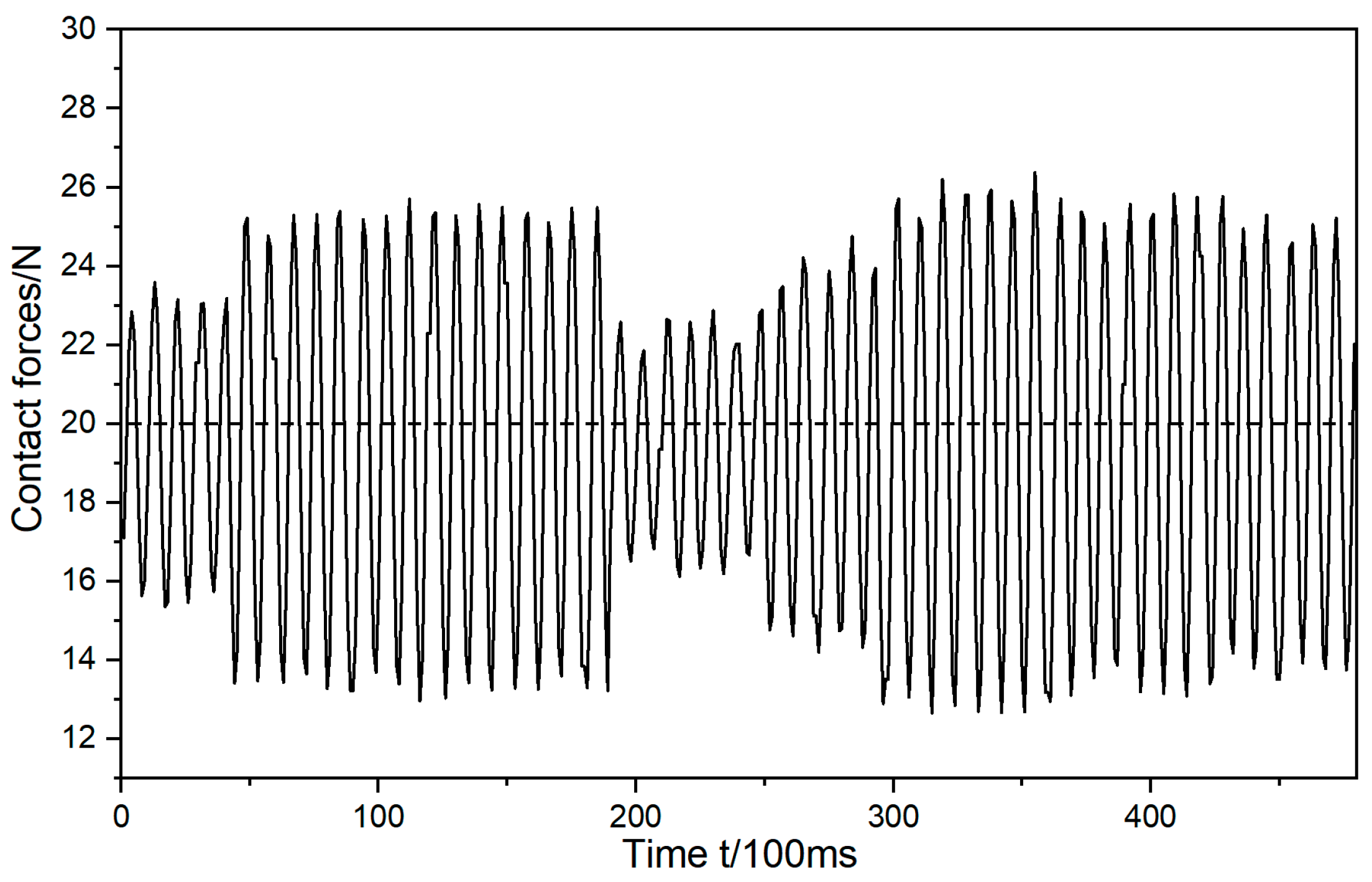
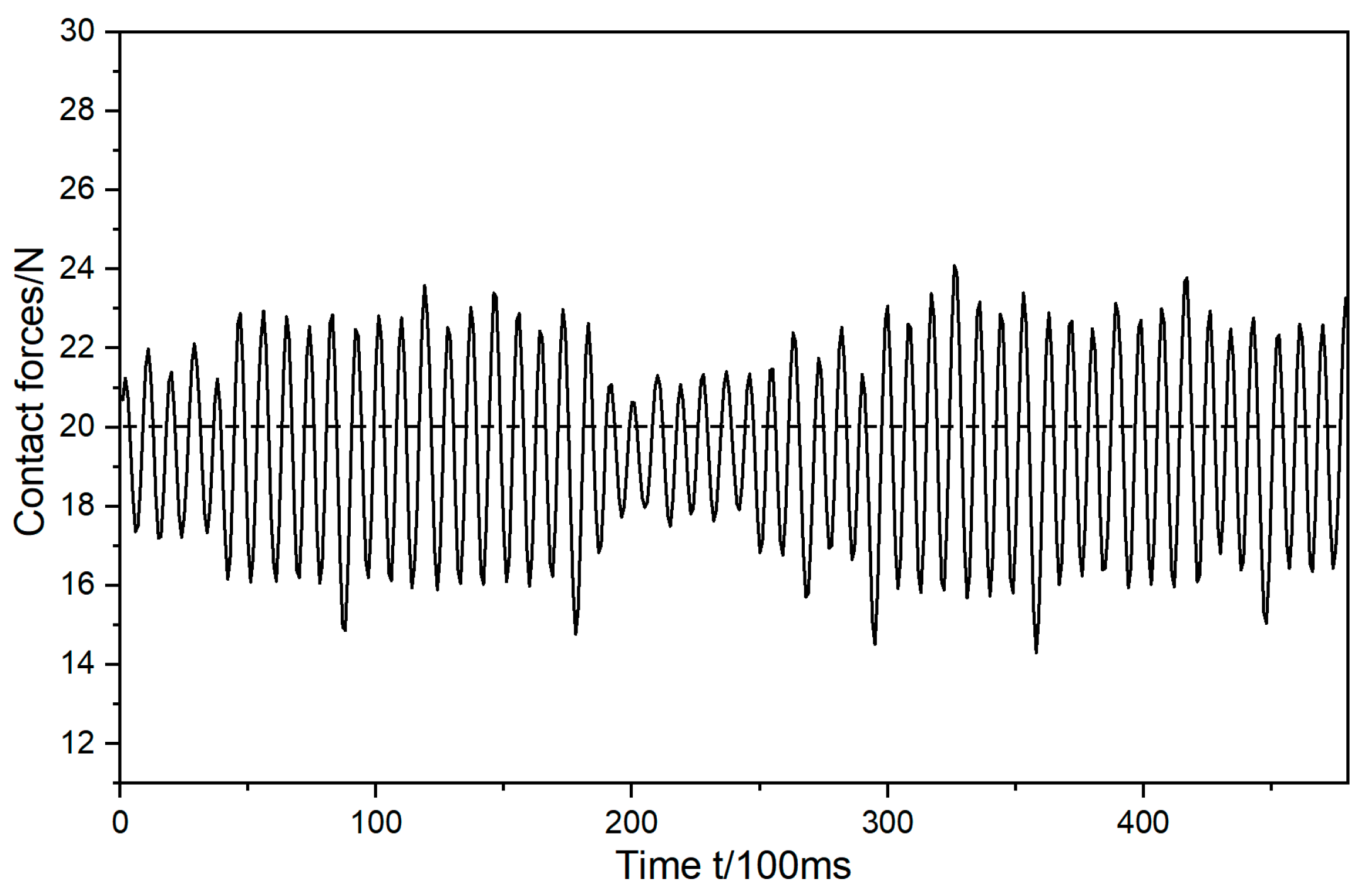
This article presents the results of a constant-force-tracking experiment employing the aforementioned method, enabling the robot to operate under both impedance control and genetic algorithm conditions. The objective was to subject the robot to a constant-force grinding test with a normal force set at 20 N. The robot initially tracked and ground based on the pre-programmed trajectory and subsequently engaged in grinding based on the estimated grinding trajectory derived from the 3D model of the workpiece and environmental parameters. The alterations in the normal force during the grinding process were observed in both conditions, as shown in Figure 3 and Figure 4.
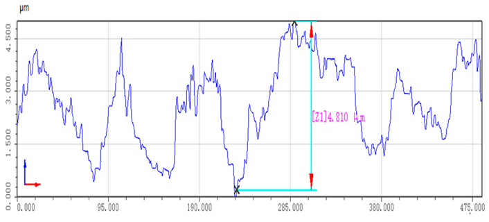
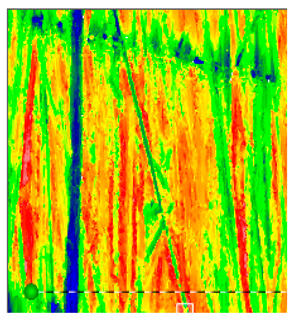
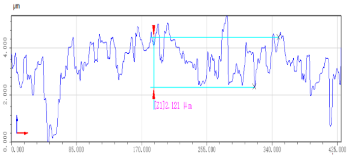
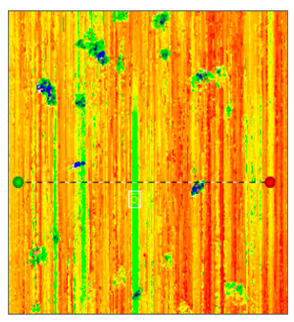
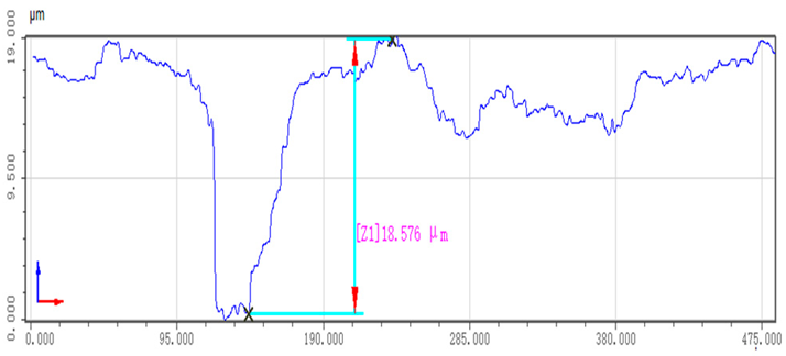
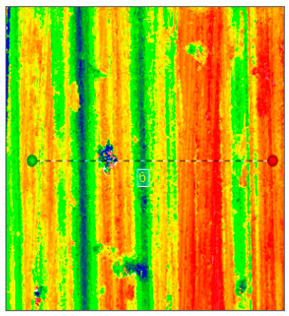
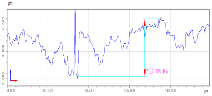
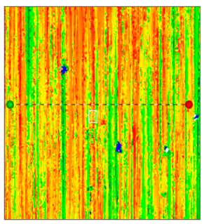
The tracking test of the normal force during the grinding process, as described above, revealed that the grinding trajectory estimated based on the 3D model of the workpiece and environmental parameters had a notable impact on reducing the normal force during motion. It effectively brought the normal force closer to 20 N, with the normal force decreasing from 20 ± 8 N to 20 ± 5 N, marking a reduction of 37.5%. To assess the impact of this process on the workpiece, the surface quality before and after grinding was evaluated using a white light interferometer, as illustrated in Table 1 below.
The table above clearly demonstrates that after the workpiece undergoes the polishing process, there is a significant enhancement in its surface quality. The workpiece is placed under a white light interferometer for measurement. The interferometer emits a beam of white light, which is projected onto the surface of the workpiece through an optical system. The detector captures the reflected light and records the resulting interference patterns. These patterns are generated due to the phase changes of light waves at different heights on the workpiece surface. Utilizing these height data, the software can calculate the surface roughness parameter, the Ra value. Hereinafter, the measured roughness is denoted by the Ra value. When the teaching trajectory is polished, the roughness is reduced from 8.5 μm to approximately 4.2 μm. Furthermore, the polishing trajectory estimated based on the 3D model of the workpiece and environmental parameters reduces the roughness from 8.5 μm to around 3.2 μm, signifying a substantial improvement in the surface quality of the polished workpiece. However, upon inspecting the 3D surface image of the workpiece, it becomes evident that the quality of the polished surface is not optimal. Scratches and other defects are still visible on the surface, indicating that further optimization is necessary to achieve the desired level of surface quality.

3.2. Optimizing Grinding Trajectory Based on Deep Genetic Algorithm

To enhance contact force tracking and compensation in the robot grinding process, a trajectory adaptive generation method is employed based on the three-dimensional model of the workpiece and the estimation of environmental parameters. This approach enhances the system’s adaptability to the external environment during the grinding process. Nevertheless, in the actual grinding process, due to the intricate nature of the workpiece contours, machining trajectory tracking errors are present and inevitable. In the realm of precision contact operations, even a minuscule displacement can lead to a rapid increase in force or torque, potentially resulting in under- or over-grinding issues.
The genetic algorithm (GA) emulates the biological evolutionary process found in nature, and it is one of many evolutionary processes utilized in various algorithms. This algorithm is grounded in the concepts of “the survival of the fittest” and “natural selection”, which means that it keeps valuable solutions and discards the less effective ones during the quest for the optimal solution [30]. As a heuristic optimization method, GA can explore a larger solution space to find solutions. It employs mechanisms such as selection, crossover, and mutation from the natural evolution process to identify the optimal solution among multiple possibilities. Although GAs possess robust optimization capabilities, their convergence speed is insufficient, particularly in complex spaces or under ambiguous evaluation criteria [31,32]. Consequently, this study proposes integrating deep neural networks with a deep genetic algorithm to compensate for contact force errors caused by displacement deviations.
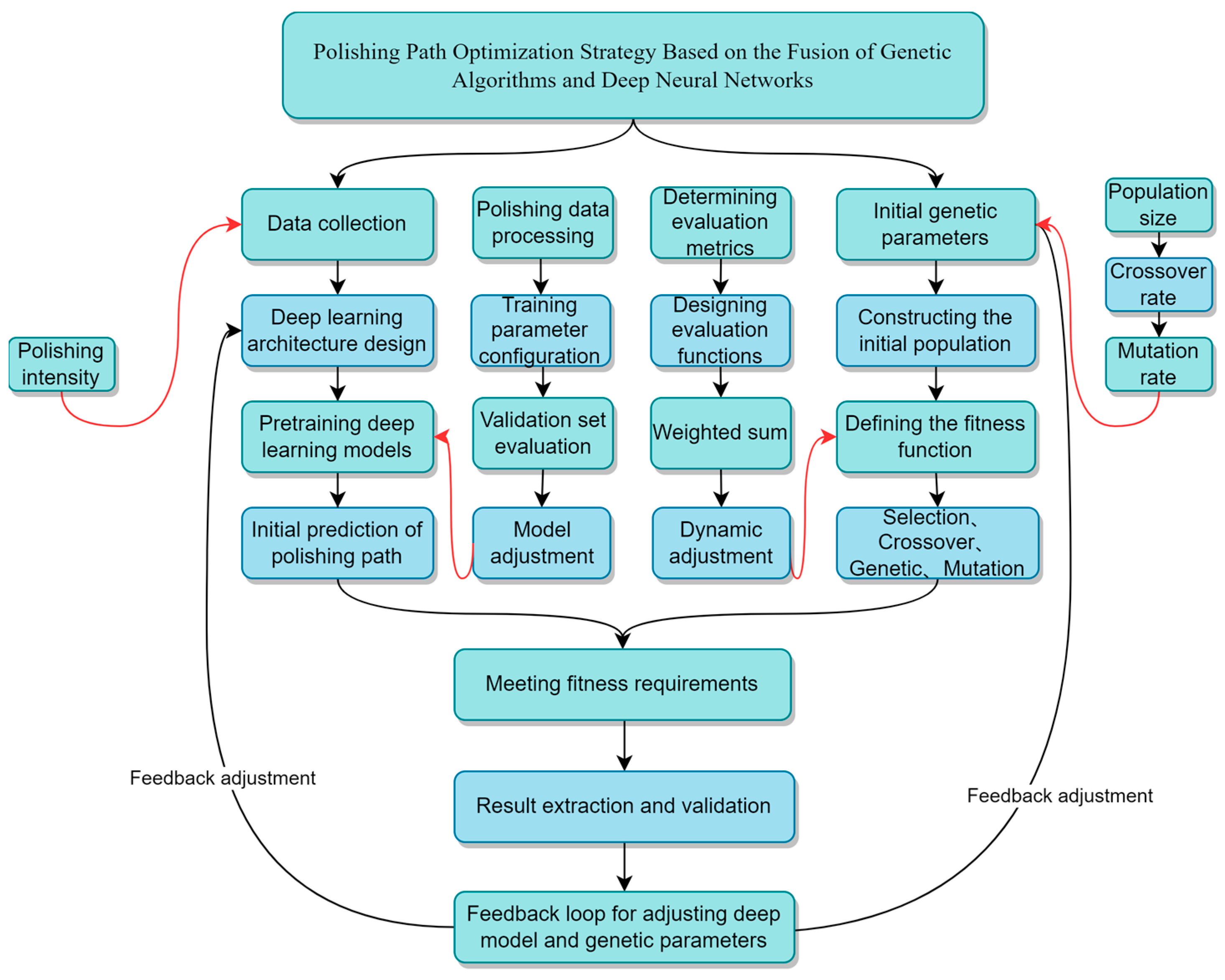
Deep neural networks (DNNs), serving as a potent and efficient predictive tool, offer an accurate initial solution for optimizing polishing trajectories [33,34]. Utilizing advanced data analysis capabilities, a DNN can precisely predict the initial polishing paths, setting an effective starting point for the initial population of the genetic algorithm (GA). This initial prediction, grounded not only in historical data and pattern recognition but also in the specific parameters and requirements of the current task, ensures the relevance and practicality of the solution [35,36,37,38]. Following this, the genetic algorithm operates on the foundation provided by the DNN. Through its unique mechanisms of natural selection and evolution, the GA iteratively refines and optimizes the polishing path [39,40]. In this process, the GA emulates the selection, crossover, and mutation processes found in nature, effectively searching for and identifying the best solution among multiple possibilities [41]. This iterative process continues until a global optimum is reached, ensuring the optimized path’s efficacy and adaptability [42,43]. The integration of DNNs and GAs not only realizes an effective fusion of data-driven and heuristic search methods but also significantly enhances the accuracy of the polishing trajectory optimization process [44,45,46]. This synergistic effect not only makes path optimization more precise but also dramatically speeds up the optimization process, achieving a speed increase of 300 to 2000 times compared to using a GA alone [47]. This significant performance enhancement is reflected not just in the expedited optimization process but also in the improved efficiency and quality of the polishing tasks, thus providing a more effective and reliable solution for complex industrial applications. The flowchart of the deep genetic algorithm is shown in Figure 5.
Optimizing the polishing trajectory through the integration of DNN and GA is a multi-stage, iterative process. The detailed steps are as follows:
(1)
Data Collection: Initially, it is necessary to gather extensive data on polishing tasks (polishing forces).
(2)
Deep Learning Model Design and Training: Considering the time dynamics during the polishing process, such as factors related to changes in polishing force over time, recurrent neural networks and DNNs are chosen as the core architecture.
(3)
Initial Prediction of the Polishing Path: Utilizing the trained deep learning model, input the current polishing task parameters and the polishing trajectory estimated based on the workpiece’s three-dimensional model and environmental parameters to obtain an initial prediction of the polishing path. This prediction takes into account the workpiece’s shape, physical characteristics, and the expected quality of polishing.
(4)
Initial Setting of Genetic Algorithm Parameters: Determine the initial parameters for the genetic algorithm, which include the scale of the population, the rate of crossover, the rate of mutation, and the upper limit of iterations.
(5)
Construction of the Initial Population: Based on the initial polishing path provided by the deep learning model, construct the initial population for the genetic algorithm. Each individual represents a potential solution for the polishing path, with the initial population containing the paths predicted by the deep model and random variations introduced on this basis.
(6)
Definition of Fitness Function: The fitness function serves as the standard for evaluating the quality of each individual and should reflect the actual requirements of the polishing task. It can be based on several factors, including the stability of the polishing process, the quality of polishing, and the time taken to complete the task.
(7)
Genetic Algorithm Iteration:
  • Selection: Based on the fitness function, select the best-performing individuals from the current population for breeding.
  • Crossover: Chosen individuals produce offspring through genetic exchange, mimicking reproduction in nature.
  • Mutation: Randomly alter parts of certain offspring’s genes to increase population diversity.
  • Evaluation: After the new-generation population emerges, reassess it using the fitness function.
(8)
Termination Condition Assessment: The algorithm concludes if it reaches the preset maximum number of iterations, or if the best individual in the population achieves a fitness level that meets task requirements. If the maximum iterations are reached without attaining a satisfactory result, the algorithm will return the best solution found thus far. Additionally, an alert or error message will be generated to inform the user of the suboptimal conclusion. The user can then consider adjusting the algorithm’s parameters or adopting alternative strategies for improved outcomes in subsequent runs.
(9)
Result Extraction and Verification: Identify the individual with the highest fitness from the final population as the optimal polishing path. Then, implement this path in actual polishing tasks, gather feedback data, and verify the path’s effectiveness.
(10)
Feedback Loop: Adjust the parameters of the deep learning model and genetic algorithm based on feedback from actual polishing results. Through continuous feedback loops, the model will constantly learn and improve, enhancing its adaptability and predictive accuracy for future polishing tasks.
Through the above feedback loops, the advanced genetic algorithm continuously refines the polishing path, ultimately identifying an optimal global trajectory for robotic path planning.
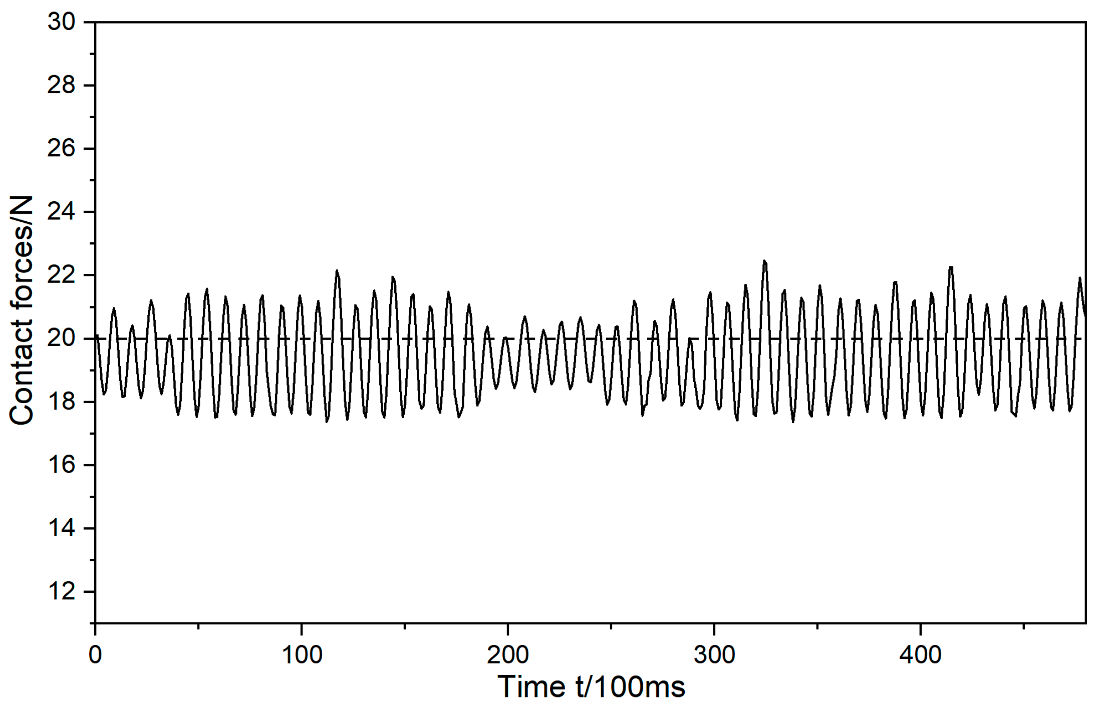
In this paper, a control method is adopted that combines adaptive reference trajectory generation based on the estimation of environmental parameters and deep genetic algorithms. This approach not only provides the control system with robust stability but also enables the precise control of force by the robot without requiring exact environmental information. The method was subjected to constant-force-tracking experiments, and, under identical experimental conditions as depicted in Figure 4 and Figure 5, with an expected grinding normal force of 20 N, force-tracking tests were carried out using the grinding trajectory optimized by the genetic algorithm. The variation in normal force during the grinding process was closely observed.
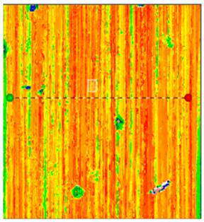
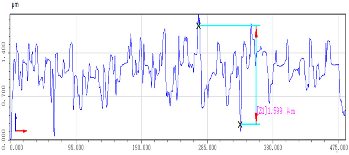
As depicted in Figure 6, the grinding normal force, optimized using the deep genetic algorithm, demonstrates stable control at approximately 20 ± 2.5 N. This control is notably concentrated around the desired force, resulting in a 68% reduction in grinding normal force compared to the demonstration teaching and a 50% reduction compared to the method based on the three-dimensional model of the workpiece and the estimation of environmental parameters. The grinding process is considerably more stable and exhibits significant improvements in optimization in comparison to the demonstration teaching and the method based on the estimation of the three-dimensional model of the workpiece and environmental parameters. The grinding trajectory is evidently optimized, and the genetic algorithm showcases enhanced adaptability, enabling more effective completion of the grinding task and improving the quality of the ground surface. Details regarding the post-grinding surface conditions of the workpiece are provided in the following Table 2.
Following optimization through deep genetic algorithms, it is evident that the surface quality and uniformity of the workpiece have been significantly enhanced. The roughness is now reduced to approximately 2.2 μm, marking a remarkable 47% improvement in roughness accuracy compared to the teaching-based grinding method and a 31% enhancement compared to the grinding method based on the estimation of the three-dimensional workpiece model and environmental parameters. Additionally, the surface quality across the entire part is notably consistent, with occasional protrusions that may result from excessive grinding. These protrusions can be mitigated by reducing the amount of grinding.

4. Flexible Grinding Experiment

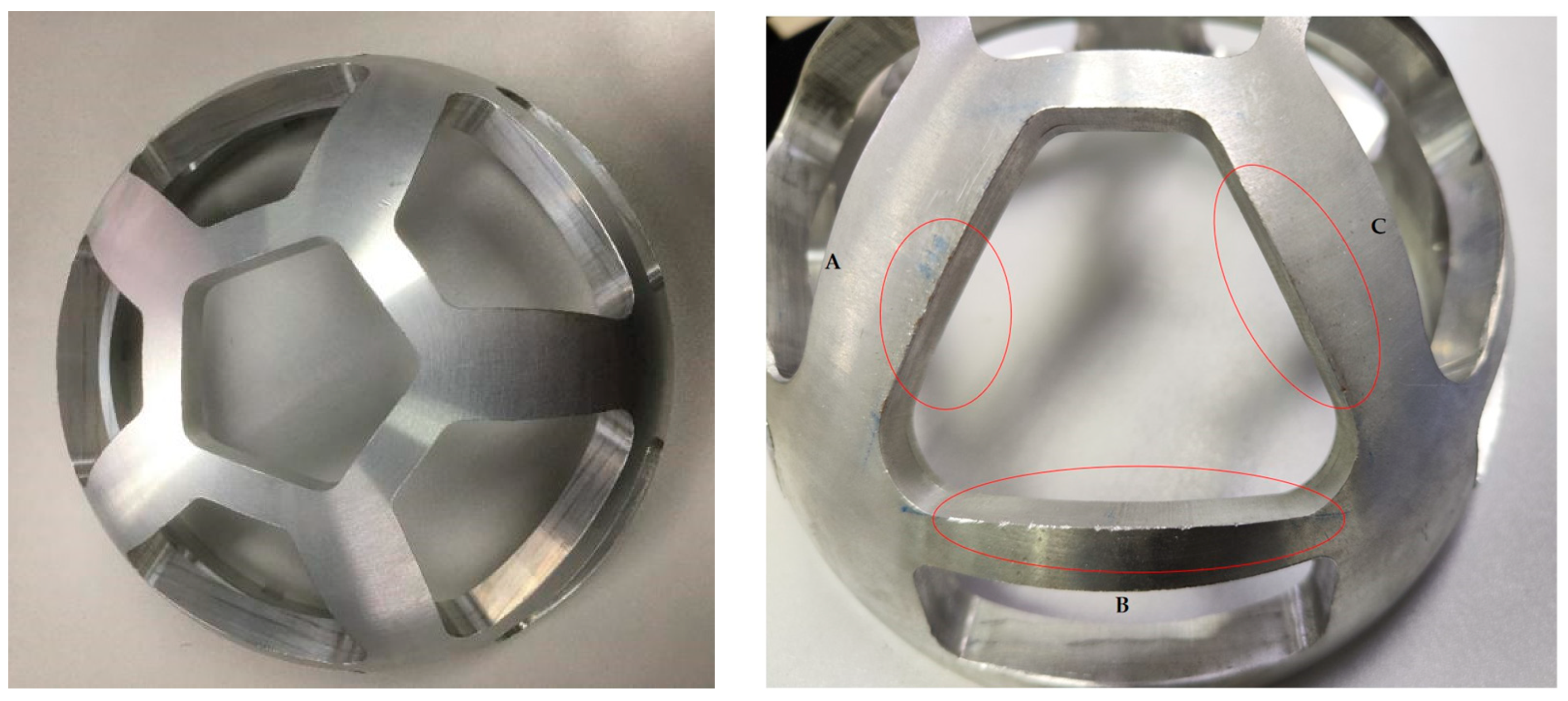
To assess the effectiveness of the proposed method outlined above, for this paper, an experimental platform for conducting research on the grinding of complex-shaped casting workpieces was established. After the machining of the complex-shaped casting workpiece, it is apparent that the surface at point A is uneven, and there are noticeable burrs at points C and B, as depicted in Figure 7.
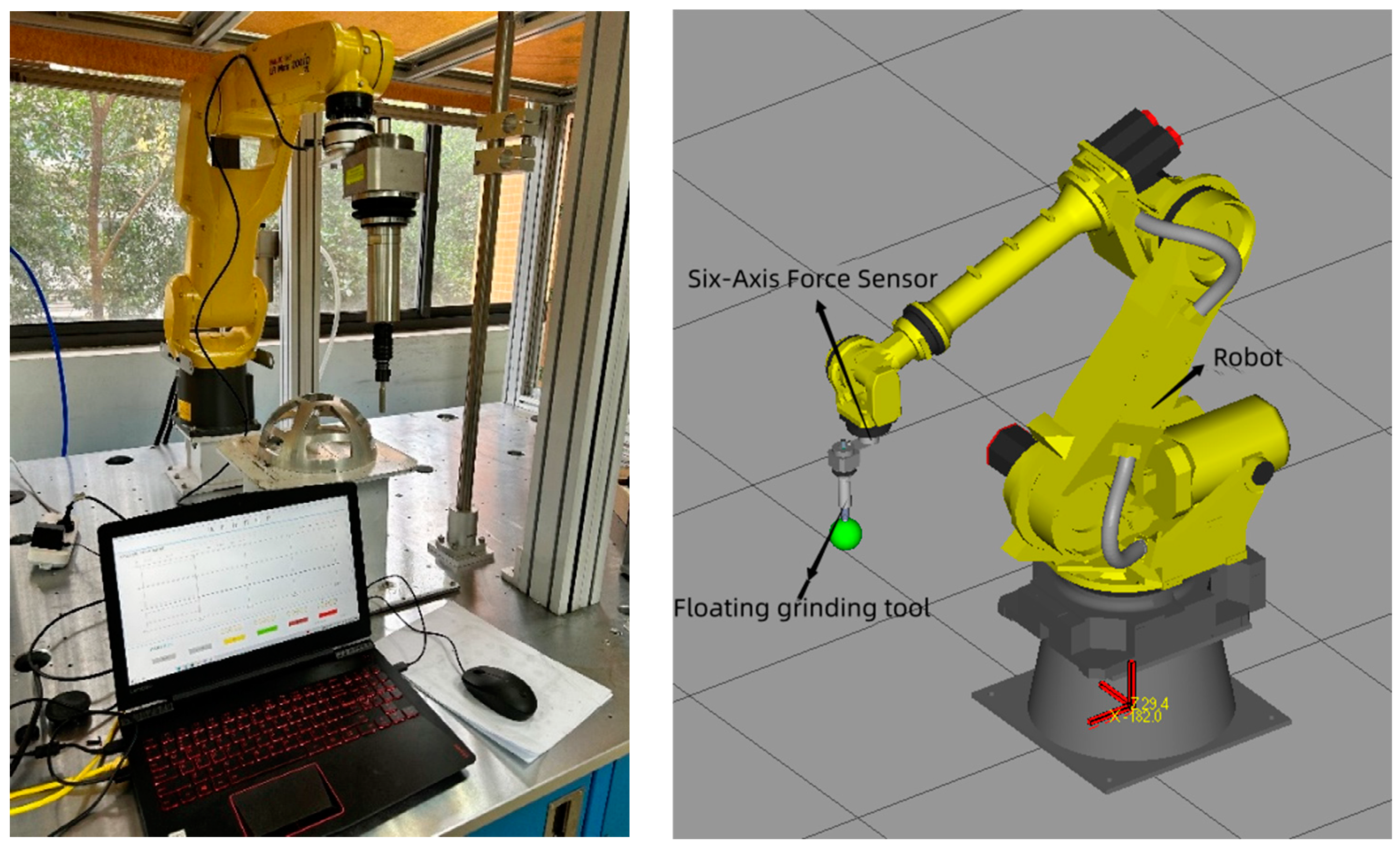
Based on the analysis of the previous workpiece, an experimental platform was set up to automate the deburring and surface grinding processes, ultimately improving the surface finish quality of the workpieces. This platform features a FANUC six-axis industrial robot as the motion platform, fitted with a six-axis force sensor at its end effector, a floating grinding spindle, and the necessary tooling. The force sensor is strategically placed between the robot’s flange and the floating grinding spindle, as illustrated in Figure 8.
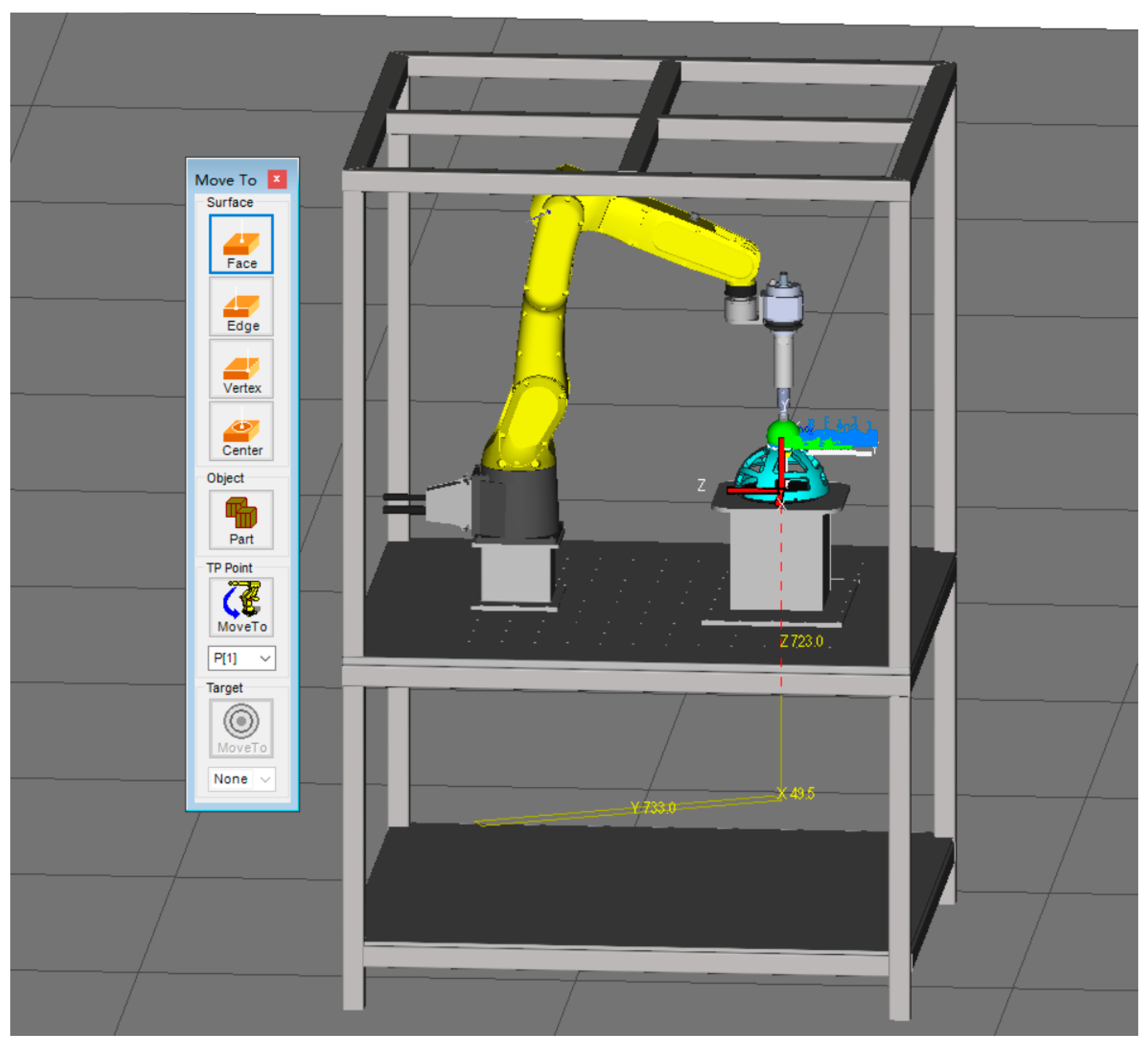
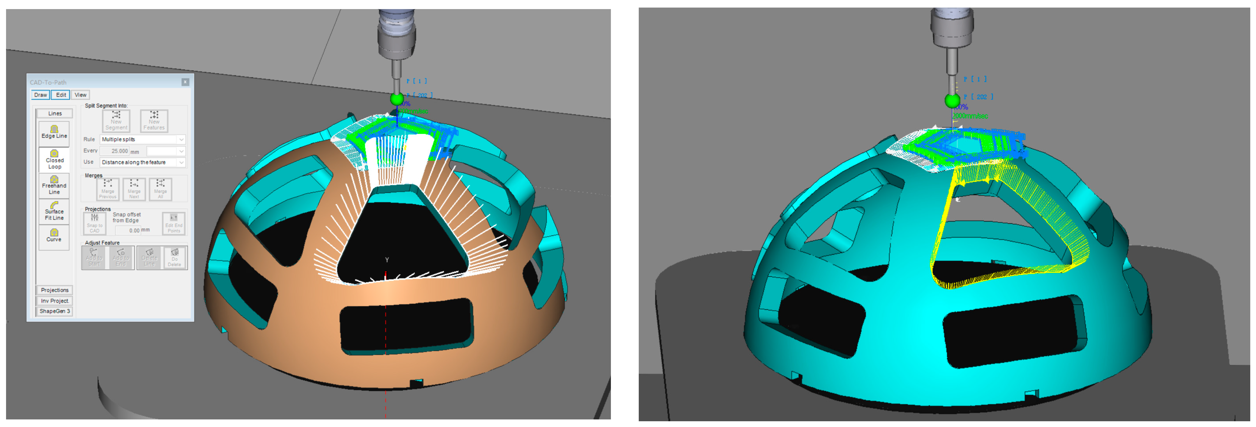
Upon scrutinizing the surface of the complex-shaped workpiece, the initial trajectory planning process is initiated. This involves leveraging RoboGuide for offline programming, where the CAD data of the irregular sphere are imported into the system. Subsequently, workpiece features are extracted, initially establishing a positioning point. Three angular points on the irregular sphere are then obtained using the MoveTo feature in RoboGuide V8.3 simulation software, and the program responsible for creating these positioning points is recorded within the teaching unit. Following the extraction of workpiece features, a grinding trajectory is generated, and its teaching points are retained in the teaching unit. Ultimately, the designated positioning points and the grinding trajectory program are exported to the actual robot controller. They are then integrated with the robot’s user and tool coordinates within the simulated workstation, effectively completing the programming of the preliminary trajectory, as shown in Figure 9 and Figure 10.
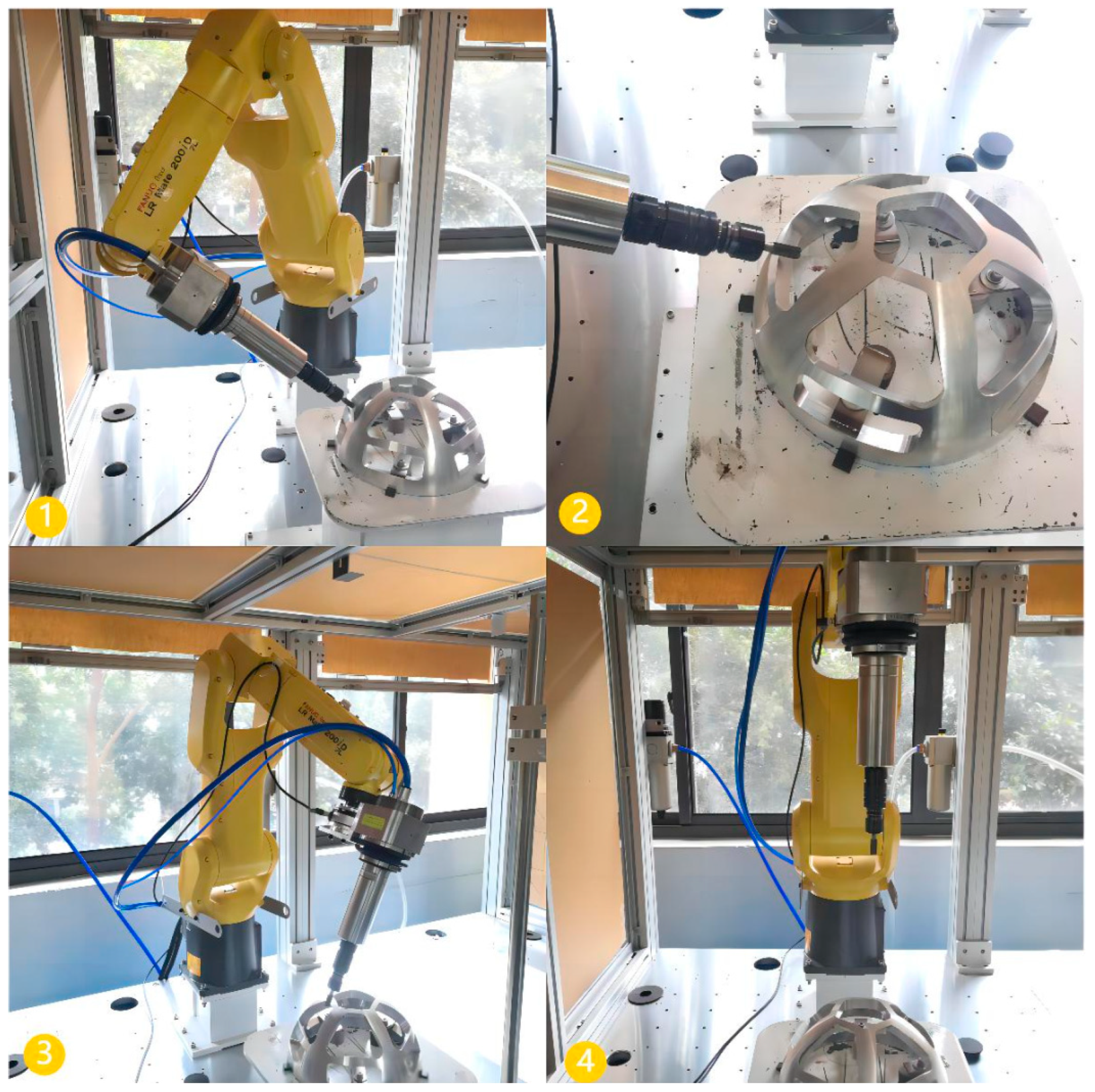
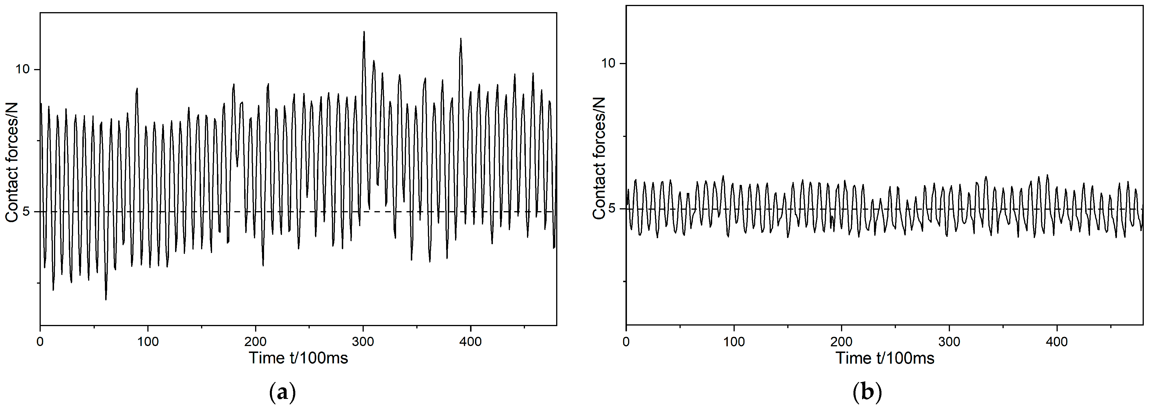
Building on the initial trajectory, this study utilizes a control method that combines adaptive reference trajectory generation based on the estimation of environmental parameters and the deep genetic algorithm. This method enables the adaptive adjustment of the robot’s end position for flexible grinding control. The algorithm’s reliability was validated through the collection and analysis of the robot’s end force sensing data before and after the implementation of the control algorithm for comparative purposes. To meet the requirements of the grinding process, experimental studies on force tracking were conducted under different conditions, with expected normal vector forces of 15 N, 10 N, and 5 N, as shown in Figure 11.
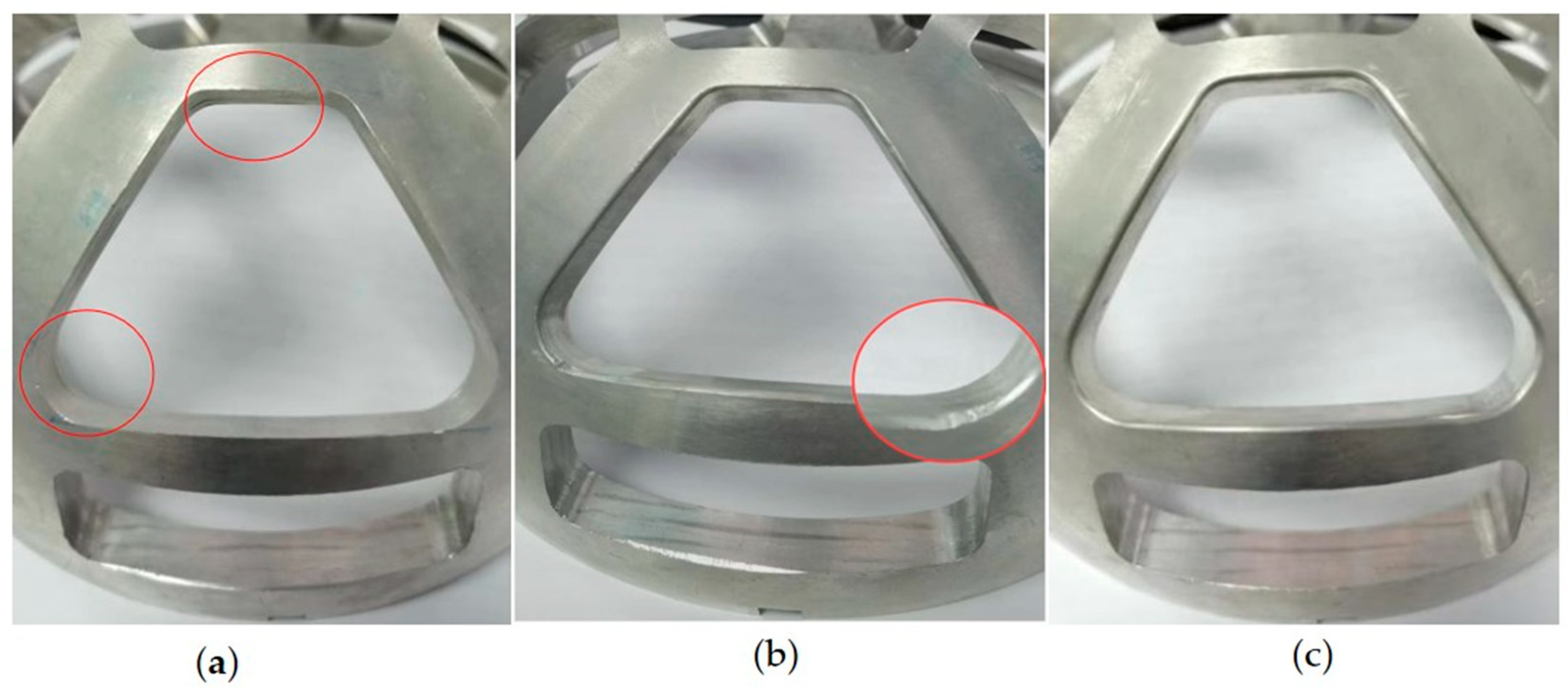
To evaluate the impact of force-controlled grinding, this paper presents an analysis of the workpiece’s surface condition before and after grinding conducted by observing its shaped surface. Prior to the polishing of the workpiece, as illustrated in Figure 12a, noticeable protrusions, significant spurs, and edge burrs are present. After the workpiece is subjected to grinding using the demonstration trajectory and the optimized trajectory, as shown in Figure 12b,c, a comparison reveals that the pronounced burrs that existed before grinding during the demonstration trajectory grinding, particularly at the part’s rounded corners, indicate instances of over-grinding and under-grinding (as seen in Figure 12b). However, after undergoing grinding with the optimized trajectory, the workpiece surface shows no discernible traces of machining.
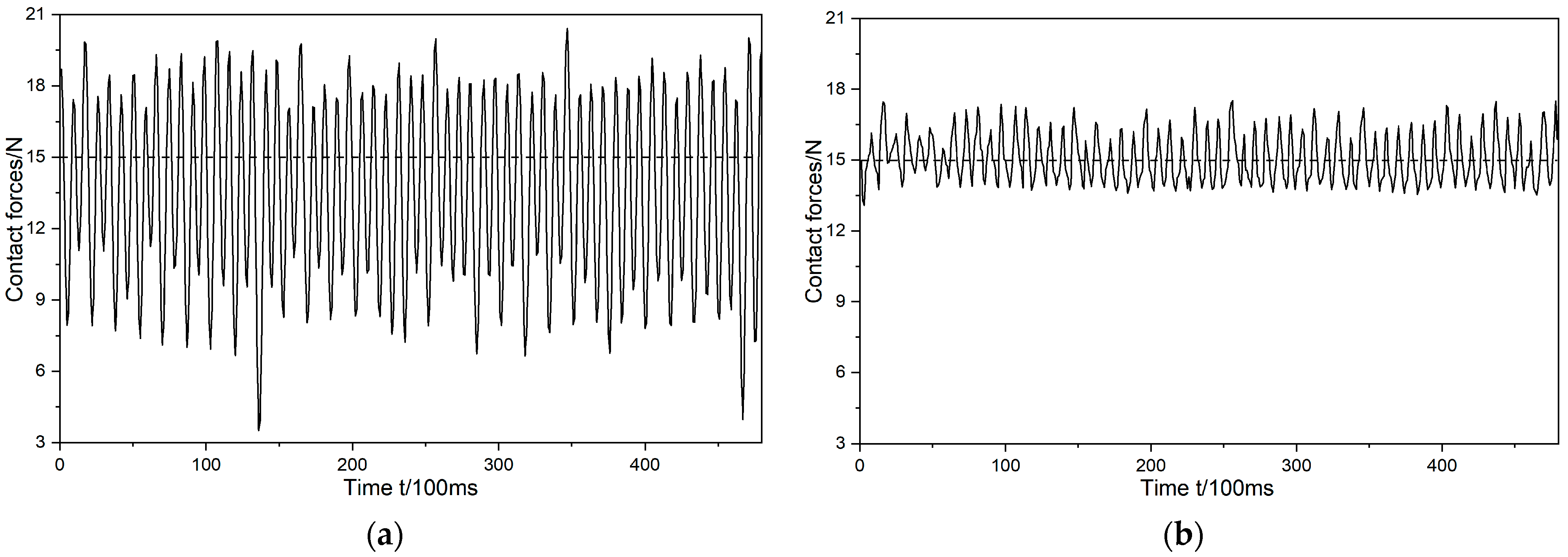
The state of the grinding force before and after optimization was analyzed by collecting information on the state of the grinding normal force during robotic grinding with a desired force of 15 N, as shown in Figure 13.
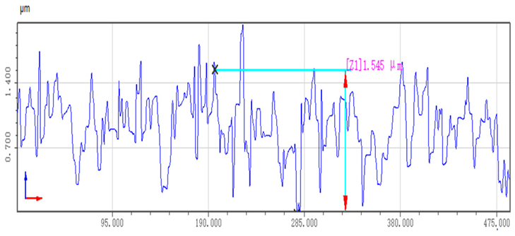
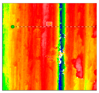
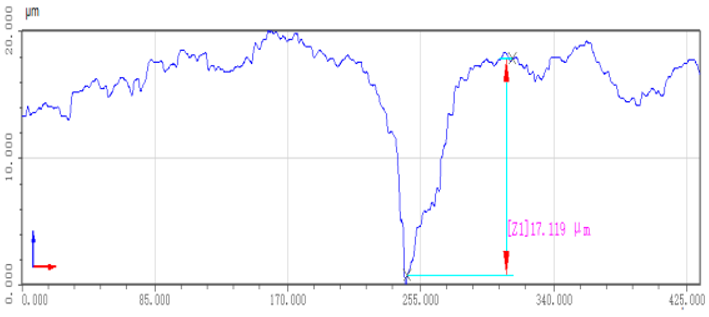
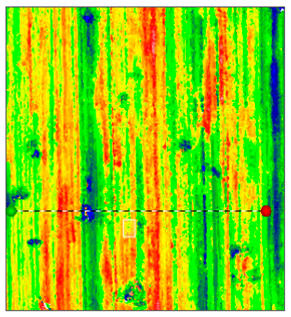
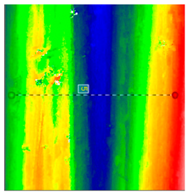
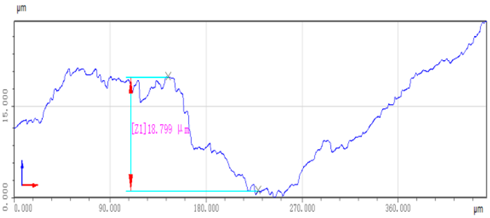
Under the desired force setting of 15 N, the grinding normal force, after optimization based on the estimation of environmental parameters and the deep genetic algorithm, demonstrates stable control at approximately 15 ± 2 N, maintaining its proximity to the target force throughout the entire grinding process. This remarkable stability represents a 71.4% reduction in the normal grinding force compared to the pre-optimization levels, which were around 15 ± 7 N. This substantial decrease significantly enhances the stability of the grinding process. A comparison of the workpiece surfaces before and after optimization is provided in Table 3.
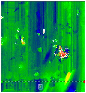
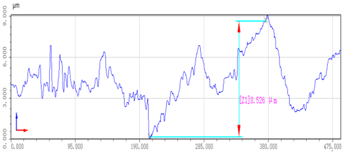
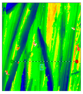
The table above, depicting the surface quality of the workpiece, highlights the significant improvement achieved after grinding. When the workpiece undergoes grinding following the teaching trajectory, the roughness is reduced from the initial 17.5 μm to approximately 6.3 μm. However, the surface quality of the polished workpiece after this grinding is less than satisfactory, featuring scratches and bumps. However, after grinding with the optimized trajectory, the surface roughness of the workpiece significantly is reduced from the initial 17.5 μm to approximately 1.5 μm. This represents a remarkable 76% improvement in roughness accuracy compared to the teaching trajectory grinding. The flatness and surface quality of the sanded plane are notably enhanced, with the raised portions of the workpiece being largely eliminated.
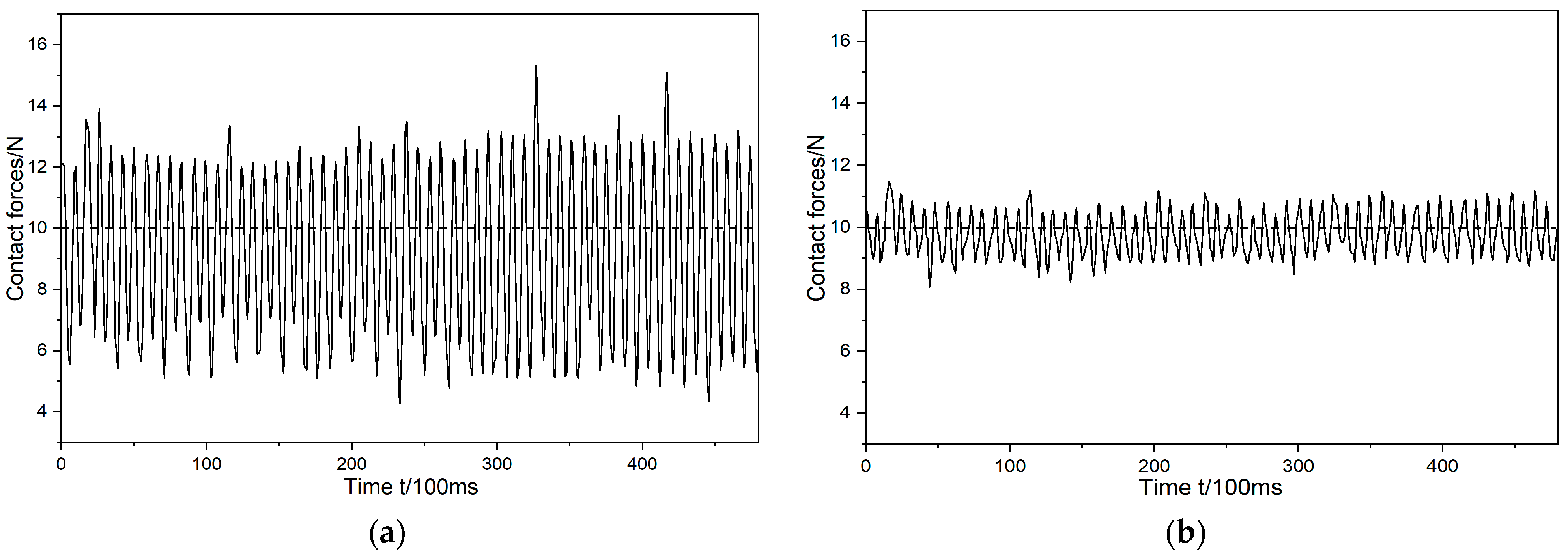
The analysis of the grinding force state before and after optimization involved collecting data on the condition of the grinding normal force during robotic grinding with a target force of 10 N. This analysis aims to assess the impact of the optimization process on the grinding force, as shown in Figure 14.
Under the desired force setting of 10 N, the grinding normal force, after optimization based on the estimation of environmental parameters and the deep genetic algorithm, demonstrates stable control at approximately 10 ± 1.5 N. The control method closely surrounds the target force and achieves exceptional stability throughout the entire grinding operation. The normal force during grinding has been reduced by 70% compared to the pre-optimization force of approximately 10 ± 5 N, indicating a significant improvement in grinding stability. The impact of this optimization on the workpiece’s surface quality before and after grinding is presented in Table 4 below.
The data in the table above clearly demonstrate a substantial improvement in the workpiece’s surface quality after the grinding process. When the workpiece undergoes grinding following the teaching trajectory, the roughness is reduced from the initial 17.1 μm to approximately 6.0 μm. However, the post-grinding surface quality remains subpar, with issues like scratches and protrusions still evident. In contrast, after the optimized trajectory grinding, the roughness experiences a more significant reduction, decreasing from 17.1 μm to approximately 1.6 μm. This represents a notable 73% improvement in roughness accuracy compared to manual trajectory grinding. The enhancement is further reflected in the significantly improved flatness and overall surface quality, with nearly all protruding elements effectively eliminated.
The analysis of the grinding force state before and after optimization continued with the collection of data on the grinding normal force during robotic grinding with a target force of 5 N, providing further insight into the impact of optimization on the grinding force, as shown in Figure 15.
Under the desired force setting of 5 N, the grinding normal force, after optimization based on the estimation of environmental parameters and the deep genetic algorithm, is consistently controlled at approximately 5 ± 1 N. This control remains concentrated near the desired force and maintains stability throughout the entire grinding process. Compared to the pre-optimization levels of approximately 5 ± 4 N, the grinding normal force is reduced by 75%, indicating a notable improvement in grinding stability. The impact of this optimization on the workpiece’s surface quality before and after grinding is presented in Table 5 below.
An analysis of the workpiece surface quality from the table above underscores a considerable improvement following the grinding process. When the teaching trajectory was employed for grinding, the surface roughness decreased from an unsanded state of 18.7 μm to approximately 6.6 μm. Nevertheless, the quality of the result was unimpressive, marred by scratches and protrusions. Conversely, with the application of an optimized grinding trajectory, the surface roughness experienced a substantial reduction, dropping from 18.7 μm to an estimated 1.4 μm. This represents a notable 78% enhancement in roughness accuracy compared to the manual grinding approach. This improvement significantly bolstered the planar uniformity and overall surface quality, effectively eliminating almost all surface irregularities.
Combining the experimental data and results presented above, it is evident that the effect of force control tracking is superior after optimization based on the estimation of environmental parameters and the deep genetic algorithm. The roughness is reduced from 18.7 μm to approximately 1.6 μm, meeting the requirements for surface roughness on complex-shaped workpieces. Additionally, the surface exhibits uniformity and good consistency after grinding.

5. Conclusions

(1)
Addressing the challenge of under-grinding and over-grinding in the grinding process of complex-shaped casting workpieces, this paper presents research on optimizing the grinding trajectory using force-sensing information. It also introduces a novel force-tracking control strategy aimed at enhancing the accuracy of contact force tracking during the grinding process.
(2)
This paper commences with an analytical study of the impedance control model. Building upon this impedance control framework, it presents research on a grinding trajectory adaptive generation method that combines the three-dimensional model of the workpiece, impedance control, and environmental parameter estimation. This paper then introduces the use of a deep genetic algorithm to compensate for contact force errors resulting from positional discrepancies. This optimization of the grinding trajectory is followed by the presentation of experimental research that led to the achievement of stable control of the grinding normal force at the expected contact force of 20 N, maintaining a level of around 20 ± 2.5 N. This marks a significant 68% reduction in grinding normal force compared to the teaching trajectory grinding. The entire grinding process demonstrates relative stability, with roughness reduced to approximately 2.2 μm, representing a 47% improvement in roughness accuracy over the teaching trajectory grinding. Furthermore, surface quality across various parts exhibits uniformity, contributing to enhanced accuracy of contact force tracking.
(3)
This paper presents a comprehensive analytical study of the technological characteristics of irregularly shaped castings and establishes a dedicated experimental platform for validation. In the experiments, conducted under expected normal forces of 5 N, 10 N, and 15 N, the normal force during grinding was consistently stabilized at 5 ± 1 N, 10 ± 1.5 N, and 15 ± 2 N, respectively. These results represent reductions of 71.4%, 70%, and 75% compared to the teaching trajectory grinding, thereby ensuring process stability. Following the grinding process, the workpiece surfaces exhibit remarkable smoothness, with roughness values under the three different conditions decreasing significantly from 17.5 μm, 17.1 μm, and 18.7 μm to 1.5 μm, 1.6 μm, and 1.4 μm, respectively. These improvements represent substantial enhancements of 76%, 73%, and 78% compared to the teaching trajectory grinding roughness values of 6.3 μm, 6.0 μm, and 6.6 μm. The uniformity and consistency of the post-grinding surfaces not only fully meet the roughness criteria for complex curved workpieces but also underscore the efficacy of the method in precisely controlling contact forces in robotic contact-oriented tasks.

Author Contributions

M.M. carried out the experimental design, algorithm derivation, and verification. M.M. and C.Z., fusion of deep neural networks with genetic algorithms; Z.L. and L.Z. analyzed the experimental effect; L.Z. performed the experimental data collection and analysis; Z.L. and W.F. conducted literature research and data collection and analysis. T.W. and X.Z. jointly completed the collection and analysis of the experimental polishing effect diagrams. All authors were involved in writing and reviewing the manuscript. All authors have read and agreed to the published version of the manuscript.

Funding

This work was supported by the Chongqing Research Program of Basic Research and Frontier Technology (Grant No. CSTB2022nscq-LZX0052), Science and Technology Research Program of Chongqing Municipal Education Commission (Grant No. KJZD-K201901503, Grant No. KJZD-M202201501, Grant No. KJQN202201503, Grant No. KJQN202201508), and the Innovation Program for Master Students of Chongqing University of Science and Technology (Grant No. YKJCX2220316).

Institutional Review Board Statement

Not applicable.

Informed Consent Statement

Not applicable.

Data Availability Statement

Due to privacy or ethical restrictions, data can be provided upon request. The data used in this study can be provided upon request to the corresponding author, and are not publicly available.

Acknowledgments

The authors acknowledge the anonymous reviewers and editors whose thoughtful comments helped to improve this manuscript.

Conflicts of Interest

The authors declare no conflict of interest.

References

  1. Ott, C.; Mukherjee, R.; Nakamura, Y. A hybrid system framework for unified impedance and admittance control. J. Intell. Robot. Syst. 2015, 78, 359–375. [Google Scholar] [CrossRef]
  2. Yang, R.; Yang, C.; Chen, M.; Na, J. Adaptive impedance control of robot manipulators based on Q-learning and disturbance observer. Syst. Sci. Control Eng. 2017, 5, 287–300. [Google Scholar] [CrossRef]
  3. Roveda, L.; Pallucca, G.; Pedrocchi, N.; Braghin, F.; Tosatti, L.M. Iterative learning procedure with reinforcement for high-accuracy force tracking in robotized tasks. IEEE Trans. Ind. Inform. 2017, 14, 1753–1763. [Google Scholar] [CrossRef]
  4. Kronander, K.; Billard, A. Stability Considerations for Variable Impedance Control. IEEE Trans. Robot. 2017, 32, 1298–1305. [Google Scholar] [CrossRef]
  5. Sharifi, M.; Behzadipour, S.; Vossoughi, G. Nonlinear model reference adaptive impedance control for human-robot interactions. Control Eng. Pract. 2014, 32, 9–27. [Google Scholar] [CrossRef]
  6. Braun, D.; Howard, M.; Vijayakumar, S. Optimal variable stiffness control: Formulation and application to explosive movement tasks. Auton. Robot. 2012, 33, 237–253. [Google Scholar] [CrossRef]
  7. Dong, Y.; Ren, B. UDE-Based Variable Impedance Control of Uncertain Robot Systems. IEEE Trans. Syst. Man Cybern. Syst. 2019, 49, 2487–2498. [Google Scholar] [CrossRef]
  8. Ding, Y.; Zhao, J.C.; Min, X. Impedance Control and Parameter Optimization of Surface Polishing Robot Based on Reinforcement Learning. Proc. Inst. Mech. Eng. Part B J. Eng. Manuf. 2023, 237, 216–228. [Google Scholar] [CrossRef]
  9. Dai, S.; Liu, S.; Ji, W.; Li, S. Vibration Suppression in Macro–Micro Grinding System of Aeroengine Blade Based on Impedance Compensation Prediction Control Strategy. Int. J. Adv. Manuf. Technol. 2023, 125, 793–807. [Google Scholar] [CrossRef]
  10. Mallapragada, V.; Erol, D.; Sarkar, N. A New Method of Force Control for Unknown Environments. In Proceedings of the IEEE/RSJ International Conference on Intelligent Robots and Systems, Beijing, China, 9–13 October 2006; pp. 4509–4514. [Google Scholar]
  11. Calanca, A.; Fiorini, P. Understanding environment-adaptive force control of series elastic actuators. IEEE/AsME Trans. Mechatron. 2018, 23, 413–423. [Google Scholar] [CrossRef]
  12. Lee, K.; Buss, M. Force tracking impedance control with variable target stiffness. IFAC Proc. Vol. 2008, 41, 6751–6756. [Google Scholar] [CrossRef]
  13. Zhang, L.; Zhang, C.; Fan, W. Robotic Magnetorheological Finishing Technology Based on Constant Polishing Force Control. Appl. Sci. 2022, 12, 3737. [Google Scholar] [CrossRef]
  14. Zhou, H.; Ma, S.; Wang, G.; Deng, Y.; Liu, Z. A hybrid control strategy for grinding and polishing robot based on adaptive impedance control. Adv. Mech. Eng. 2021, 13, 168781402110040. [Google Scholar] [CrossRef]
  15. Fateh, M.M.; Azargoshasb, S. Discrete adaptive fuzzy control for asymptotic tracking of robotic manipulators. Nonlinear Dyn. 2014, 78, 2195–2204. [Google Scholar] [CrossRef]
  16. Fateh, S.; Fateh, M.M. Adaptive Fuzzy Control of Robot Manipulators with Asymptotic Tracking Performance. J. Control Autom. Electr. Syst. 2020, 31, 52–61. [Google Scholar] [CrossRef]
  17. Lakshminarayanan, S.; Kana, S.; Mohan, D.M.; Manyar, O.M.; Then, D.; Campolo, D. An adaptive framework for robotic polishing based on impedance control. Int. J. Adv. Manuf. Technol. 2021, 112, 401–417. [Google Scholar] [CrossRef]
  18. Young, S.; Rose, D.; Karnowski, T.; Lim, S.; Patton, R. Optimizing Deep Learning Hyper-Parameters through an Evolutionary Algorithm. In Proceedings of the Workshop on Machine Learning in High-Performance Computing Environments, Austin, TX, USA, 15–20 November 2015; pp. 4:1–18. [Google Scholar]
  19. Lamos-Sweeney, J. Deep Learning Using Genetic Algorithms. Master’s Thesis, Department of Rochester Institute of Technology, New York, NY, USA, 2012. [Google Scholar]
  20. Lander, S. An Evolutionary Method for Training Auto Encoders for Deep Learning Networks. Master’s Thesis, Department of Computer Science, Missouri University, Columbia, MO, USA, 2014. [Google Scholar]
  21. Shao, L.; Liu, L.; Li, X. Feature Learning for Image Classification via Multi-Objective Genetic Programming. IEEE Trans. Neural Netw. Learn. Syst. 2014, 25, 1359–1371. [Google Scholar] [CrossRef]
  22. Roveda, L.; Pedrocchi, N.; Tosatti, L.M. Exploiting impedance shaping approaches to overcome force overshoots in delicate interaction tasks. Int. J. Adv. Robot. Syst. 2016, 13, 1729881416662771. [Google Scholar] [CrossRef]
  23. Liang, X.; Zhao, H.; Li, X.; Ding, H. Force tracking impedance control with unknown environment via an iterative learning algorithm. Sci. China-Inf. Sci. 2019, 62, 050215. [Google Scholar] [CrossRef]
  24. Beltran-Hernandez, C.C.; Petit, D.; Ramirez-Alpizar, I.G.; Nishi, T.; Kikuchi, S.; Matsubara, T. Learning Force Control for Contact-Rich Manipulation Tasks With Rigid Position-Controlled Robots. IEEE Robot. Autom. Lett. 2020, 5, 5709–5716. [Google Scholar] [CrossRef]
  25. Deisenroth, M.P.; Fox, D.; Rasmussen, C.E. Gaussian Processes for Data-Efficient Learning in Robotics and Control. IEEE Trans. Pattern Anal. Mach. Intell. 2015, 37, 408–423. [Google Scholar] [CrossRef] [PubMed]
  26. Isela, B.; Fernando, R. A Dynamic-compensation Approach to Impedance Control of Robot Manipulators. J. Intell. Robot. Syst. 2011, 63, 51–73. [Google Scholar]
  27. Tsuji, T.; Tanaka, Y. On-line learning of robot arm impedance using neural networks. Robot. Auton. Syst. 2005, 52, 257–271. [Google Scholar] [CrossRef]
  28. Chen, S.; Wang, Z.; Chakraborty, A.; Klecka, M.; Saunders, G.; Wen, J. Robotic Deep Rolling With Iterative Learning Motion and Force Control. IEEE Robot. Autom. Lett. 2020, 5, 5581–5588. [Google Scholar] [CrossRef]
  29. Izadbakhsh, A.; Khorashadizadeh, S.; Ghandali, S. Robust adaptive impedance control of robot manipulators using Szász–Mirakyan operator as universal approximator. ISA Trans. 2020, 106, 1–11. [Google Scholar] [CrossRef] [PubMed]
  30. Nazmara, G.; Fateh, M.M.; Ahmadi, S.M. A model-reference impedance control of robot manipulators using an adaptive fuzzy uncertainty estimator. Int. J. Comput. Intell. Syst. 2018, 11, 979–990. [Google Scholar] [CrossRef]
  31. Sohail, A. Genetic algorithms in the fields of artificial intelligence and data sciences. Ann. Data Sci. 2023, 10, 1007–1018. [Google Scholar] [CrossRef]
  32. Khatri, K.C.A.; Shah, K.B.; Logeshwaran, J.; Shrestha, A. Genetic algorithm based techno-economic optimization of an isolated hybrid energy system. CRF 2023, 8, 1447–1450. [Google Scholar]
  33. Gu, Z.; Lu, W.; Fan, Y.; Gao, Y. Automated simplified structural modeling method for megatall buildings based on genetic algorithm. J. Build. Eng. 2023, 77, 107485. [Google Scholar] [CrossRef]
  34. Pan, Y.; Yang, Y.; Liu, H.; Li, W. UAVs and mobile sensors trajectories optimization with deep learning trained by genetic algorithm towards data collection scenario. Mob. Netw. Appl. 2023, 28, 808–823. [Google Scholar] [CrossRef]
  35. Ayan, E. Genetic Algorithm-Based Hyperparameter Optimization for Convolutional Neural Networks in the Classification of Crop Pests. Arab. J. Sci. Eng. 2023, 8, 1–15. [Google Scholar] [CrossRef]
  36. Voronkov, A.D.; Diane, S.A.K. Continuous Genetic Algorithm for Grasping an Object of a Priori Unknown Shape by a Robotic Manipulator. Russ. Technol. J. 2023, 11, 18–30. [Google Scholar] [CrossRef]
  37. Sehgal, A.; La, H.; Louis, S.; Nguyen, H. Deep reinforcement learning using genetic algorithm for parameter optimization. In Proceedings of the 2019 Third IEEE International Conference on Robotic Computing (IRC), Naples, Italy, 25–27 February 2019; IEEE: Piscataway, NJ, USA, 2019; pp. 596–601. [Google Scholar]
  38. Lee, S.; Kim, J.; Kang, H.; Kang, D.-Y.; Park, J. Genetic algorithm based deep learning neural network structure and hyperparameter optimization. Appl. Sci. 2021, 11, 744. [Google Scholar] [CrossRef]
  39. Wang, L.C.; Chen, C.C.; Hsu, C.C. Applying machine learning and GA for process parameter optimization in car steering wheel manufacturing. Int. J. Adv. Manuf. Technol. 2022, 122, 4389–4403. [Google Scholar] [CrossRef]
  40. Qie, X.; Kang, C.; Zong, G.; Chen, S. Trajectory planning and simulation study of redundant robotic arm for upper limb rehabilitation based on back propagation neural network and genetic algorithm. Sensors 2022, 22, 4071. [Google Scholar] [CrossRef]
  41. Rajasimman, M.A.V.; Manoharan, R.K.; Subramani, N.; Aridoss, M.; Galety, M.G. Robust facial expression recognition using an evolutionary algorithm with a deep learning model. Appl. Sci. 2022, 13, 468. [Google Scholar] [CrossRef]
  42. Moussafir, M.; Chaibi, H.; Saadane, R.; Chehri, A.; Rharras, A.E.; Jeon, G. Design of efficient techniques for tomato leaf disease detection using genetic algorithm-based and deep neural networks. Plant Soil 2022, 479, 251–266. [Google Scholar] [CrossRef]
  43. Mishra, V.; Kane, L. A survey of designing convolutional neural network using evolutionary algorithms. Artif. Intell. Rev. 2023, 56, 5095–5132. [Google Scholar] [CrossRef]
  44. Kotyrba, M.; Volna, E.; Habiballa, H.; Czyz, J. The Influence of Genetic Algorithms on Learning Possibilities of Artificial Neural Networks. Computers 2022, 11, 70. [Google Scholar] [CrossRef]
  45. Erden, C. Genetic algorithm-based hyperparameter optimization of deep learning models for PM2.5 time-series prediction. Int. J. Environ. Sci. Technol. 2023, 20, 2959–2982. [Google Scholar] [CrossRef]
  46. Tameswar, K.; Suddul, G.; Dookhitram, K. A hybrid deep learning approach with genetic and coral reefs metaheuristics for enhanced defect detection in software. Int. J. Inf. Manag. Data Insights 2022, 2, 100105. [Google Scholar] [CrossRef]
  47. Ji, H.; Wang, M.; Sun, M.; Liu, Q. Neural network classifier based on genetic algorithm image segmentation of subject robot optimisation system. Int. J. Grid Util. Comput. 2021, 12, 369–379. [Google Scholar] [CrossRef]
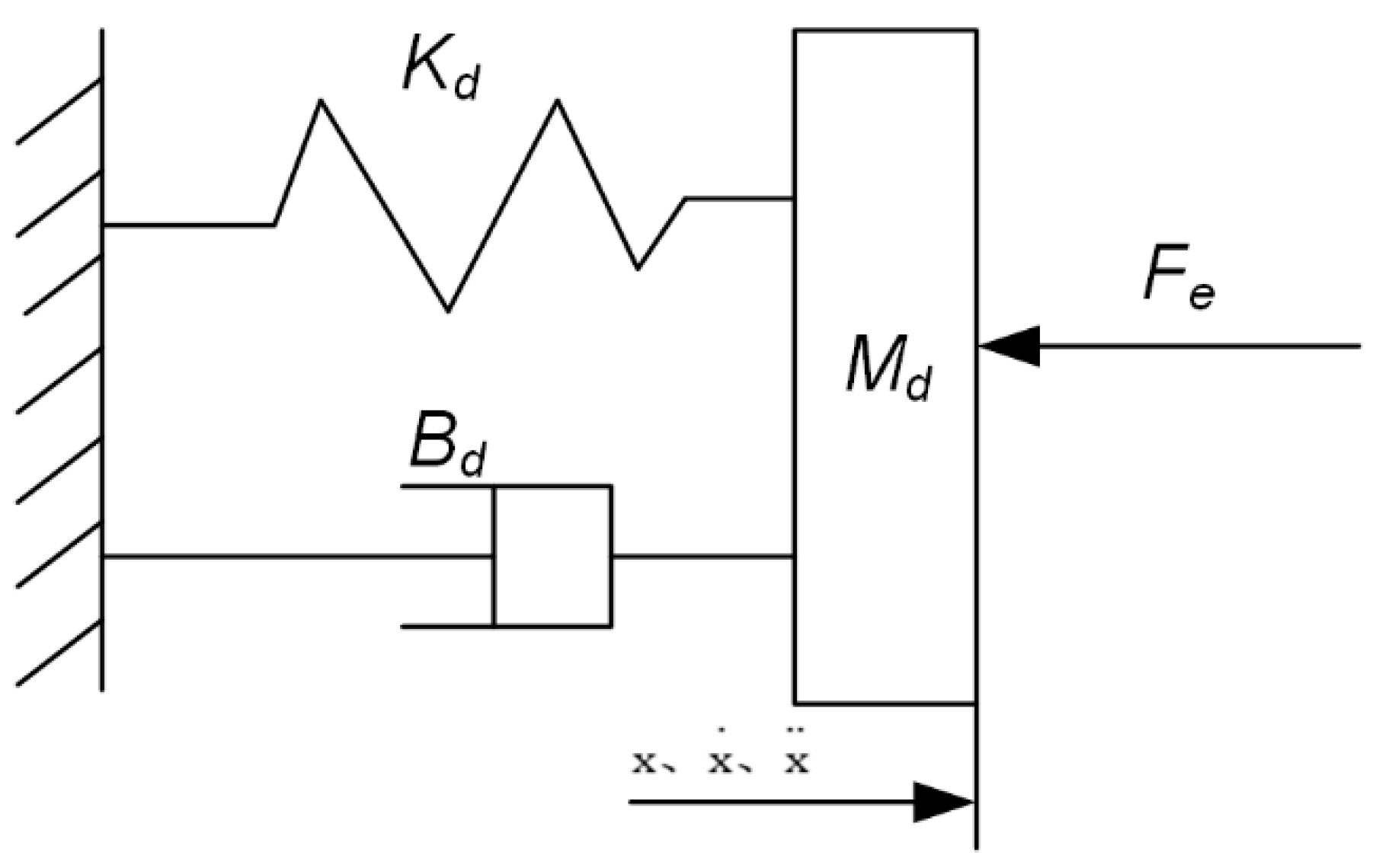
Figure 1. The spring–mass–damping model.
Machines 11 01075 g001
Figure 2. Impedance control system framework.
Machines 11 01075 g002
Figure 3. Variations in normal force during the teach–track polishing process.
Machines 11 01075 g003
Figure 4. Variation in normal force during grinding based on 3D model and estimation of environmental parameters.
Machines 11 01075 g004
Figure 5. Flowchart of the deep genetic algorithm.
Machines 11 01075 g005
Figure 6. Variations in normal force during grinding process based on deep genetic algorithm.
Machines 11 01075 g006
Figure 7. Complex-shaped casting class workpiece grinding analysis.
Machines 11 01075 g007
Figure 8. Experimental device.
Machines 11 01075 g008
Figure 9. Positioning point acquisition.
Machines 11 01075 g009
Figure 10. Generation of grinding trajectory.
Machines 11 01075 g010
Figure 11. Robot grinding process. (1) grinding for the acquisition of positioning point contours; (2) the process of grinding down contours; (3) the process of grinding upper contours; (4) Robot returns to zero point.
Machines 11 01075 g011
Figure 12. Comparison of effect before and after grinding: (a) workpiece before grinding; (b) demonstration track after grinding; (c) optimized trajectory after grinding.
Machines 11 01075 g012
Figure 13. Variations in normal force during the polishing process with a desired force of 15 N: (a) variations in normal force during grinding process based on teaching trajectory; (b) variations in normal force during grinding process based on optimized trajectory.
Machines 11 01075 g013
Figure 14. Variations in normal force during the polishing process with a desired force of 10 N: (a) variations in normal force during grinding process based on teaching trajectory; (b) variations in normal force during grinding process based on optimized trajectory.
Machines 11 01075 g014
Figure 15. Variations in normal force during the polishing process with a desired force of 5 N: (a) variations in normal force during grinding process based on teaching trajectory; (b) variations in normal force during grinding process based on optimized trajectory.
Machines 11 01075 g015
Table 1. Surface quality of the workpiece before and after grinding.
Working ConditionContour Analysis ImageSurface Roughness Trend Graph
Unpolished workpiece surfaceMachines 11 01075 i001Machines 11 01075 i002
Robot teaching trajectory grindingMachines 11 01075 i003Machines 11 01075 i004
Estimating grinding trajectory based on environmental parametersMachines 11 01075 i005Machines 11 01075 i006
Table 2. Surface quality of workpiece after optimization based on deep genetic algorithm.
Working ConditionContour Analysis ImageSurface Roughness Trend Graph
Workpiece surface after optimization by deep genetic algorithmMachines 11 01075 i007Machines 11 01075 i008
Table 3. Surface quality of ground workpieces before and after optimization with a desired force of 15 N.
Working ConditionContour Analysis ImageSurface Roughness Trend Graph
Unpolished workpiece Machines 11 01075 i009Machines 11 01075 i010
Teaching trajectory grindingMachines 11 01075 i011Machines 11 01075 i012
Optimization of grinding trajectoriesMachines 11 01075 i013Machines 11 01075 i014
Table 4. Surface quality of ground workpieces before and after optimization with a desired force of 10 N.
Working ConditionContour Analysis ImageSurface Roughness Trend Graph
Unpolished workpiece surfaceMachines 11 01075 i015Machines 11 01075 i016
Robot teaching trajectory grindingMachines 11 01075 i017Machines 11 01075 i018
Optimization of grinding trajectoriesMachines 11 01075 i019Machines 11 01075 i020
Table 5. Surface quality of polished workpieces before and after optimization with a desired force of 5 N.
Working ConditionContour Analysis ImageSurface Roughness Trend Graph
Unpolished workpiece surfaceMachines 11 01075 i021Machines 11 01075 i022
Teaching trajectory grindingMachines 11 01075 i023Machines 11 01075 i024
Optimization of grinding trajectoriesMachines 11 01075 i025Machines 11 01075 i026
Disclaimer/Publisher’s Note: The statements, opinions and data contained in all publications are solely those of the individual author(s) and contributor(s) and not of MDPI and/or the editor(s). MDPI and/or the editor(s) disclaim responsibility for any injury to people or property resulting from any ideas, methods, instructions or products referred to in the content.