1. Introduction
Nature demonstrates an unparalleled capacity for creating highly functional and intricate designs, many of which remain beyond the current reach of human engineering. The foundational theories of Darwin and Dawkins, focusing on evolution and cumulative selection, have shed light on how these designs are not spontaneous but have evolved over millions of years through a non-random, cumulative process [
1,
2]. This evolutionary process has resulted in a rich tapestry of natural designs characterized by a diverse array of geometrical patterns, from fractals and spirals to tessellations and symmetries as seen in
Figure 1. These geometrical examples not only demonstrate the potential for direct application in engineering but also illustrate how natural selection has tailored various patterns to form structures that are highly efficient [
3].
Optimal designs in human-engineered products can often be achieved by emulating effective strategies found in nature. Various terms have been used to describe this approach, each with their own differences. ‘Biomimetics’ and ‘Biomimicry,’ introduced by Otto Schmitt and Janine Benyus, respectively, refer to the imitation of natural principles for technical solutions, with biomimicry placing an additional emphasis on sustainability [
8,
9]. ‘Bionics’ often intersects with these concepts but is more widely recognized in the context of prosthetics and robotics [
10]. For this study, the focus will be on ‘Bio-inspired design’, a term that encompasses the use of nature’s strategies in a way that combines both natural patterns and technical innovation. This approach does not involve direct copying from nature but rather draws inspiration from it, aiming to enhance technical solutions by integrating nature-inspired designs [
11]. It is this concept of ‘Bio-inspired design’ that forms the foundation of this research and guides the methodology throughout this article.
In rare cases, it may be possible to find the perfect solution to the problem, directly looking for it in nature [
12]. But usually, there is no specific example found in nature that helps the engineer achieve the best solution. It is obvious that it is not possible to wait millions of years for natural selection to work in a certain living being in order to imitate its results. The process of natural evolution can be simulated, though, in order to achieve the most optimized solution possible for a specific problem. Diverse simulation-driven design methods resemble nature’s evolutionary process [
13]. The main objective of these methods is to imitate nature’s way of designing with numerical or computational methods. These methods do not necessarily mimic the process of cumulative selection itself (as genetic algorithms would); they are based on obtaining the most optimized solution possible for well-defined initial and boundary conditions. This is why ways of designing structures such as generative design and topology optimization can be considered as bio-inspired design methods [
12].
The evolution process can be simulated and it is a powerful tool for a designer, but sometimes the solution to the designer’s problem appears directly in different scale and size into a natural example. This direct imitation, also known as true biomimicry, works by taking features from examples observed in nature to be applied to a certain solution [
13].
This study aims to explore the effect of three bio-inspired design methods on an aeronautic assembly tooling used to support large structural components such as fuselages and wings. These three methodologies have been chosen through an extensive investigation of the tools available in the market. In any case, variety is sought, from the more traditional ones such as simple topology optimization to more modern methods such as generative design. To cover the true biomimicry part, different options have been reviewed. Three tools have been selected to apply the three different methodologies mentioned above in order to optimize the case study and meet the structural operation requirements. In the end, the objective is to evaluate proposed designs and select the best one according to operational objectives. Additionally, the study investigates the manufacturing of the selected design at real dimensions using advanced manufacturing methods. The proper operation of the large-scale manufactured component will be assessed through operational testing.
In this study, advanced computational tools are employed to effectively translate bio-inspired design principles into practical engineering solutions. The first of these tools is Autodesk Fusion 360, a Generative Design tool. This tool will be used to demonstrate the efficiency of simulation-driven design methods in capturing the essence of bio-inspired structures. The second software, Altair Optistruct, is a topology optimization tool that represents a more traditional approach in engineering component optimization. It aims to validate the effectiveness of this established method in optimizing structural designs. Lastly, Synera, a low-code programming engineering design platform, will be utilized for its ability to hybridize different design techniques. In this study, Synera will enable a combination of topology optimization, parametric optimization, and true biomimicry—directly mimicking natural features. This integration of diverse software tools allows for a comprehensive exploration and comparative analysis of various design scenarios, evaluating the effectiveness and feasibility of bio-inspired designs in aeronautical tooling.
After a deep state-of-the-art study, not a lot of information has been found about comparisons of bio-inspired optimization methods applied to a certain use case; however, there exist some review studies that mention some of them with different classifications [
13,
14]. Instead, there is a lot of information on application of lattices [
15,
16], topology optimization [
17], generative design [
18], and the use of Voronoi patterns and other bioinspired geometries [
19,
20,
21]. The comparative study can be of great interest to know how three different methods are applied in the same research and at the same time to observe the results applied to a case study. Although a method’s turning out to be the best for the specific case studied here does not mean that it is the best methodology for other studies, it may provide clues for future research.
In this article, the fabrication method used to create a large structure (800 × 500 × 2100 mm) with complex topology due to its bioinspired design will be discussed. No literature was found regarding the fabrication of components with such complexity (topology and large size). However, there have been some studies mentioning the potential of 3D printed sand molds for complex topology parts [
22,
23]. Additionally, tests have been performed to certify that the digital model and the fabricated part behave identically in terms of vibration modes.
2. Selected Methodologies and Software
The first method to be applied to the case study is generative design. This is a broad concept and has several definitions. However, ASSESS Initiative, a multi-industry organization whose objective is to bring together key players to guide and influence software tool strategies for performing model-based analysis, simulation, and systems engineering, defined generative design as “a tool that uses algorithmic methods to generate feasible designs or outcomes from a set of performance objectives, performance constraints, and design space for specified use cases” [
24]. In this sense, generative design can be considered a bio-inspired design method because, as in the evolution process, different designs are explored to obtain the best result and the component is customized for specific boundary conditions.
The generative design can be based on several optimization methods such as topology optimization [
25], cellular automata [
26], genetic algorithms [
27], or artificial intelligence systems [
28].
To choose the most suitable generative design tool for this study, a review of the commercial software was performed. In order to be as precise as possible, the tools were compared based on the key capabilities indicated by ASSESS Initiative. This organization, backed by NAFEMS (International Association for the Engineering Modelling, Analysis and Simulation Community) defined 15 key points to rate generative design tools with the specific requirements each software item must accomplish to reach a rating of from 1 to 5, avoiding the subjectivity of this qualification. It should be mentioned that with the information that is publicly available for each of the tools it was not possible to qualify the 15 key points defined by the initiative. Thus,
Table 1 shows the 7 points that could be evaluated with the 8 commercial tools to be compared. It should be noted that this rating was made by the authors of this study and with public information without having access to any of the software. It may happen that some features of the software items are not publicly available and therefore not regarded in this qualification. In addition, it may happen that at the time of publication of this study these tools are updated; therefore, the ratings could change in some of the mentioned parameters [
24].
As can be seen in the table, the highest scoring commercial tool is Autodesk Fusion 360. Moreover, it is not only that it has the best score; it has unlimited access for all tools for students for a limited time, which is why it was also chosen. So, the first tool for analyzing the first method in this work is Fusion 360, based on topology optimization via the level-set method [
29]. To support the choice of this tool, IntrinSIM LLC conducted a review of the software items on the market and came to the conclusion that AutoDesk Fusion 360 was strongly competitive with its competitors, which also supported the choice of the tool [
30].
As a second technique, a pure topology optimization tool was employed to present a more traditional perspective. Topology optimization is iterative and boundary-condition-driven, similar to the evolutionary strategies observed in nature. This process involves an adaptive refinement of the design to meet specified loading conditions, similar to how natural structures evolve over time to adapt to environmental stresses but in a short time frame. The optimization algorithm iteratively removes material that does not significantly contribute to the structural stability, resulting in an optimized, often organic-looking form [
13]. This tool is solely based on the loading conditions applied to the structure, independent of fabrication methods or design variations. Depending on the method used, elements that do not significantly contribute to the stability of the part are eliminated. As a result, a mesh with a reduced number of elements is obtained. The number of elements to be retained can be chosen by selecting an isovalue. However, exporting the final geometry can be challenging and often requires post-processing to convert the mesh into a solid. Altair Optistruct was selected as the commercial topology optimization tool due to its established heritage of utilizing traditional methods such as SIMP [
31]. Additionally, the tool offers the capability to apply various objectives and constraints, including first natural frequency and volume constraint, among others.
For a true biomimicry perspective, Synera was selected as the tool of choice. Synera is a generative engineering software item that utilizes algorithmic and parametric design. This allows for the reuse of design algorithms and the generation of complex geometries such as natural patterns and features. Additionally, Synera can interface with other software for topology optimization, FEA, and other simulations and also has its own solvers for FEM analysis. As such, it can be considered a hybrid tool that combines true biomimicry with simulation-driven design. True biomimicry is achieved through the tool’s ability to generate and modify complex structures using geometric patterns and structures observed in nature. Within Synera, there are methods to use Voronoi cells, tree-like structures, skeleton-like structures, and some types of lattice structures. For the simulation-driven design aspect, Synera has connectors to other software to import results of different optimizations and has its own meshing tools and solvers for FEM analysis. It also has an optimizer based on MIDACO (Mixed Integer Distributed Ant Colony Optimization) for multi-objective optimizations based on the geometrical parameters of the part [
32].
3. Use Case Presentation
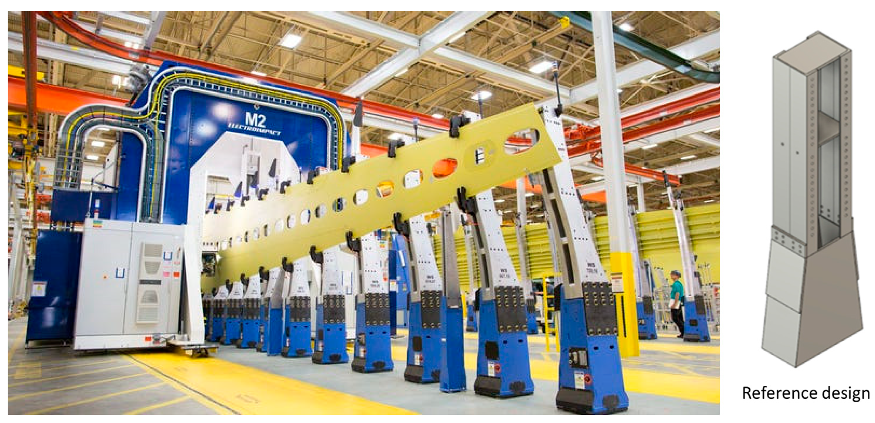
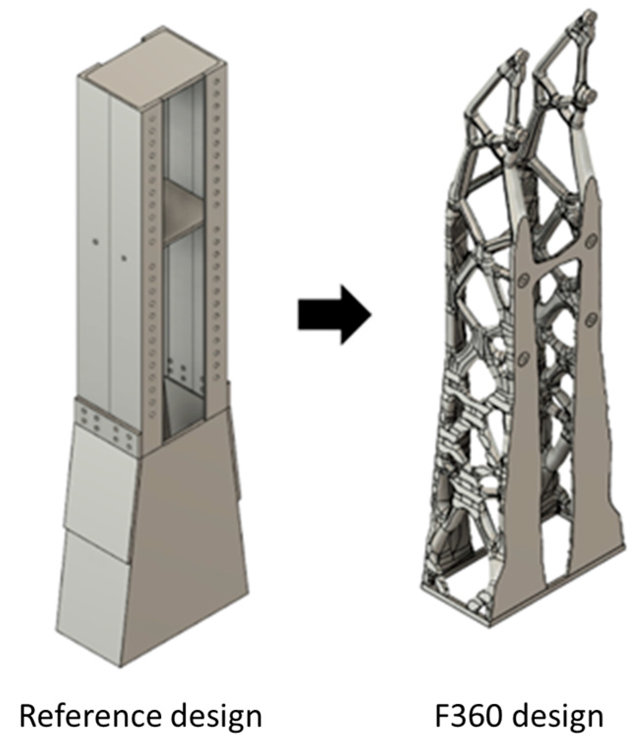
After selecting the methods and tools, the methodologies will be applied to a specific use case to compare the mechanical behavior of the outcomes. The proposed use case is an aeronautical assembly column, which is a basic element of future jigless assembly tools (see
Figure 2). This type of element would increase flexibility while reducing the number of tools, shimming, and costs. Additionally, aeronautical assembly companies could transition from classic jigs to fixtures and eventually to metrology-assisted assembly.
Aerospace assembly presents a unique challenge as it involves the assembly of large structures with tight tolerances and numerous drilling and riveting operations. Fixed toolings (jigs) are used to position and assemble components in compliance with specifications. Approximately 5% of the total cost of manufacturing an aircraft or 10% of the cost of the aircraft structure is attributed to the use of fixed toolings. The goal of the assembly sector is to reduce the costs and assembly times associated with fixed tools by decreasing their usage and increasing their reconfigurability and reusability. The ideal end condition would be “the best tooling is no tooling,” where tooling usage is minimized.
The challenges for optimizing the assembly column include reducing the mass of the tooling, ensuring part consistency, and maximizing rigidity to achieve a high enough first eigenvalue to avoid catastrophic issues during vibrational operations such as drilling.
The reference design is built by welded and bolted parts of structural steel, with a total weight of 344 kg and its first eigenfrequency is 42 Hz.
3.1. Material
Regarding the material, as different manufacturing methods are going to be considered—high-pressure die casting, gravitational casting with 3D printed sand molds, and additive manufacturing—a consistent alloy has to be selected for all of them. Furthermore, as the mass reduction and recyclability are considered key aspects of this optimization, a Si based aluminum alloy was chosen. This aluminum alloy has relatively low viscosity, which helps the processability for the different manufacturing methods [
34]. The mechanical properties of this alloy are a Young’s modulus of 71 GPa, density of 2700 g/cm
3, Poisson’s Ratio of 0.33, and yield stress of 170 MPa which can be regarded as moderate [
35]. Cu- or Zn-based Al alloys could show better properties, but their viscosity is higher, putting the manufacturing process at risk.
3.2. Loads, Constraints, and Objectives
A common goal of the design of structures is to avoid resonance of the structure in a given interval for external excitation frequencies. This can be achieved by maximizing the fundamental eigenfrequency [
36,
37]. For drilling processes in the aircraft industry, the speed for a 6 mm drill bit is approximately 3000 rpm for materials such as aluminum or Carbon Fiber Reinforced Polymers (CFRPs) [
38,
39]. This equates to a rotational speed of 50 turns per second or 50 Hz. To ensure an acceptable safety margin, the limit for this case is set at 60 Hz.
The structure must be capable of supporting different load cases. Operational loads, which account for mounting operations such as drilling and riveting, and structural loads, which are defined by the weight of the supported structure (vertical loads in fixations), must both be considered.
Operational loads are more complex to predict and can be more detrimental than structural loads. Therefore, for design purposes, various configurations of operational loads have been selected with a value of 1000 N per fixation (each column has two). Since the loads can come from different directions as seen in
Figure 3, the load cases to be studied are:
- (1)
1000 N for each fixation in −X direction
- (2)
1000 N for each fixation in +X direction
- (3)
1000 N for each fixation, upper fixation with −X and the lower fixation with +X direction
- (4)
1000 N for each fixation, upper fixation with +X and the lower fixation with −X direction
Suppose that this assembly column will be used to assemble the wing of a Boeing 737, having a total span of 35.8 m (according to [
40]) and knowing that the wings are assembled separately, half of this span is taken, 17 m. It is also known that the wing area of this aircraft is 124 m
2 and it is assumed that the average thickness of the covering of the structure is 5 mm (it can vary between 1 and 10 mm). The total volume of the material of the wing’s covering would be:
where
S is the surface area and
t is the average thickness of the soffit. The cladding material can be aluminum or CFRP with densities of 2700 kg/
and 1550 kg/
, respectively. Therefore, the weight in aluminum would be 1674 kg and in CFRP 961 kg. In addition, it would be necessary to add the stringers and ribs that can also be of both materials, which are usually 400 kg for aluminum and 250 kg in CFRP. The total weight of the wing would be 2074 kg in aluminum and 1211 kg in CFRP. The assembly columns of this type are usually placed one every meter; therefore, 17 + 1 should be placed. The weight distribution for each column would be 115 kg if the wing was made of aluminum and 67 kg if it was made of CFRP. This translates into 1130 N and 657 N, respectively. As the system is intended to be as flexible as possible, the most restrictive value will be taken and a safety factor of almost double will be applied. This value will be 2000 N to be supported by each column. The safety factor for the whole study is defined as a ratio between the reference maximum admissible value and the value we want to compare with.
4. Designing Methodology for Each Software
In the next sections, the already presented use case is going to be used as an example so the reference design is optimized with different bio-inspired design methods. The methodologies are going to be precisely described so the outcomes can be recreated for future studies.
4.1. Generative Design with Level-Set Topology Optimization (Fusion 360)
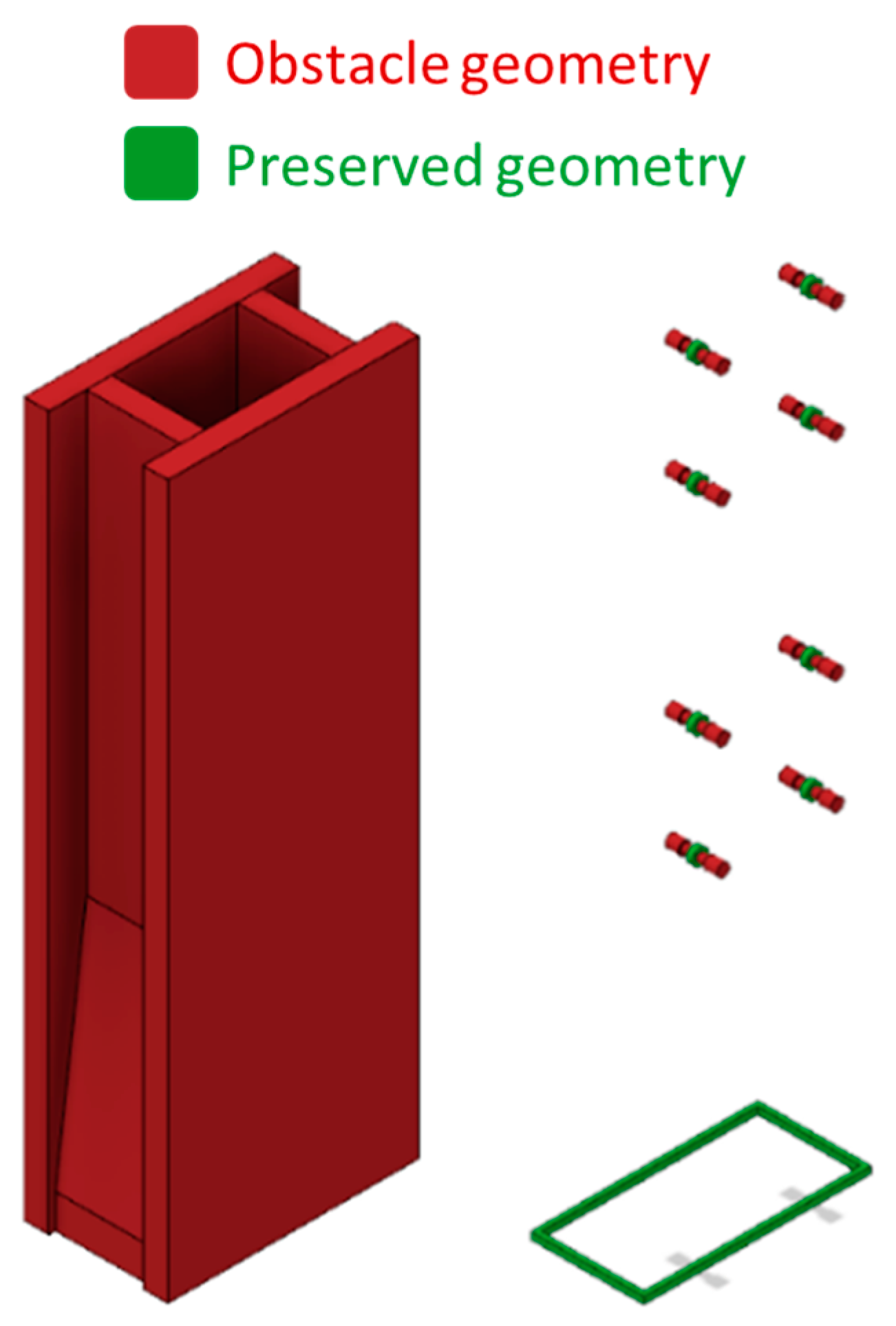
In Autodesk Fusion 360 v2.0.16490 (F360), the available design space is also divided into two different sections as shown in
Figure 4, comparable to the approach in Altair Optistruct. The preserved geometry, or non-design geometry, refers to the parts of the design that must be included in the generative design outcome. In this case, this includes the base of the column and the holes for the fixations. The obstacle geometry defines the boundaries of the design and sets the limits for the outcome generated by the software. The design and non-design geometries are the same for the Altair Optistruct case but are defined differently. The geometry sets for this study are shown in
Figure 4.
Fusion 360 has the option to select the manufacturing method and the objectives and limits of the design. For this study, as the main objective was to have the best design no matter the manufacturing process, the unrestricted mode was selected. The objective of the design can be set as minimize mass or maximize stiffness. And as limits, a minimum safety factor, a minimum first frequency mode, or/and a minimum displacement can be imposed. Vibrational stability is crucial for an assembly column, so a constraint was set to ensure that the first mode is above 60 Hz. To achieve symmetric designs without geometric singularities, the outcomes from Fusion 360 must be post-processed. A graphic view of the outcome can be seen in
Figure 5.
4.2. SIMP Topology Optimization (Altair Optistruct)
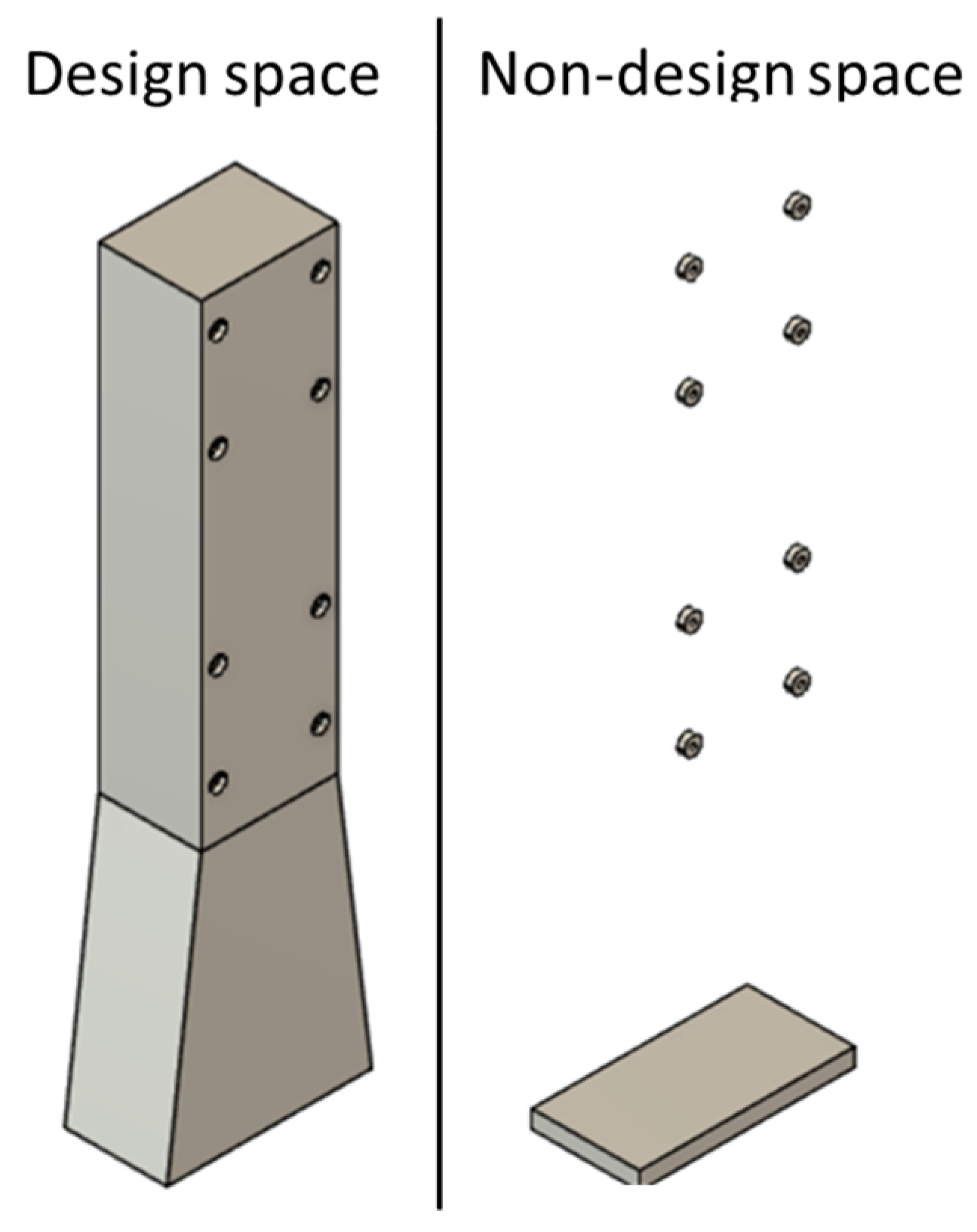
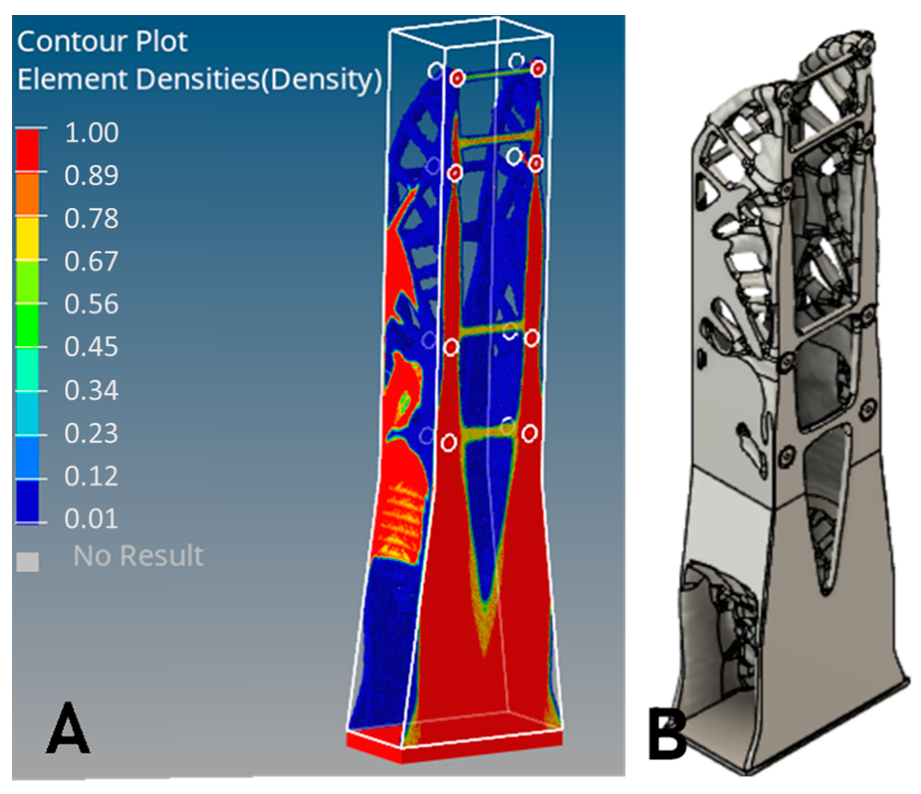
To perform this SIMP Topology Optimization analysis, the design geometry and a non-design geometry is defined, as shown in the
Figure 6. The design space occupies the same volume as the reference design and has holes that allow assembly tooling, the so-called tool clearance. The non-design space consists of a base of the structure and the holes where the fixations are screwed.
To mesh the two geometries, 7 mm trias elements were selected. A static structural study was defined as an FE simulation. The topology design variable was defined with symmetry on the XZ plane, as there are no asymmetric loads on the structure. To determine the type of result to be obtained, the constraints and objectives of the simulation were selected. The volume fraction of removed material was constrained to be less than 6.25% and the first vibration mode of the system was required to be higher than 60 Hz. The objective of the optimization was to minimize compliance while considering a weighted response of the four operational load cases. The result of the topology optimization is shown in
Figure 7B.
4.3. Hybrid Method (Generative Engineering) (Synera)
The method used in this case study is a hybrid method called generative engineering. With the help of the Synera commercial tool, which has capabilities for parametric design, connectivity with different engineering software items, i.e., Hypermesh and optimization, and natural geometrical patterns can be optimized and guided towards specific functionality. Two different designs were obtained for this case study: one based on the skeleton method and the other on the Voronoi pattern. Both designs are partially based on the results of topology optimization but apply these true biomimicry perspectives and enhance the result with parametric optimization.
To ensure efficient stress distribution, the unions between elements in both cases are based in the morphology of joints seen in nature, specifically in diatoms [
41]. Notably, these natural structures often employ rounded and smooth joints, a design feature critical for mitigating stress concentrations. Such configurations are instrumental in distributing mechanical loads more evenly, thereby enhancing the overall structural integrity. The structural efficiency of diatoms was studied experimentally and with FEM in [
42] showing a remarkable ability to withstand applied forces.
The parameter optimization, as mentioned earlier, is based in the MIDACO solver. In the approach presented in this study, the optimization process involves the careful selection of various geometrical parameters of the design. These parameters are then subjected to a series of optimization steps, where different responses are evaluated to converge on what we define as the ‘optimal result.’ This process is not just about optimizing a single objective; instead, it entails balancing multiple objectives to achieve a design that represents the best compromise among these various goals.
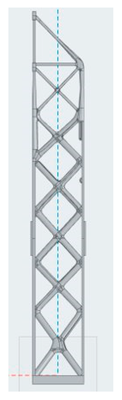
The skeleton method involves extracting load lines from topology optimization analysis and assigning diameters to these lines to create a strut-like structure. Parameter optimization is conducted on the diameters to achieve the optimal geometry for the design. In this process, the lateral skeletons are assigned a uniform diameter along their length, which is included as a key parameter in the optimization. Conversely, the vertical skeletons are designed with a gradient-based decreasing diameter as their height increases, a specification also determined through parameter optimization as seen in
Figure 8. The parameters thus comprise the constant diameter of each lateral skeleton element and the range (initial and final diameters) for the vertical skeletons. This optimization is informed by critical factors such as maximum stress, maximum deformation, and the first eigenfrequency. The integration of these parameters facilitates the setup of a comprehensive study, culminating in the precise dimensioning of the Skeleton design. The skeleton method design was selected for its known structural stability in natural organisms such as diatoms and radiolarians [
41].
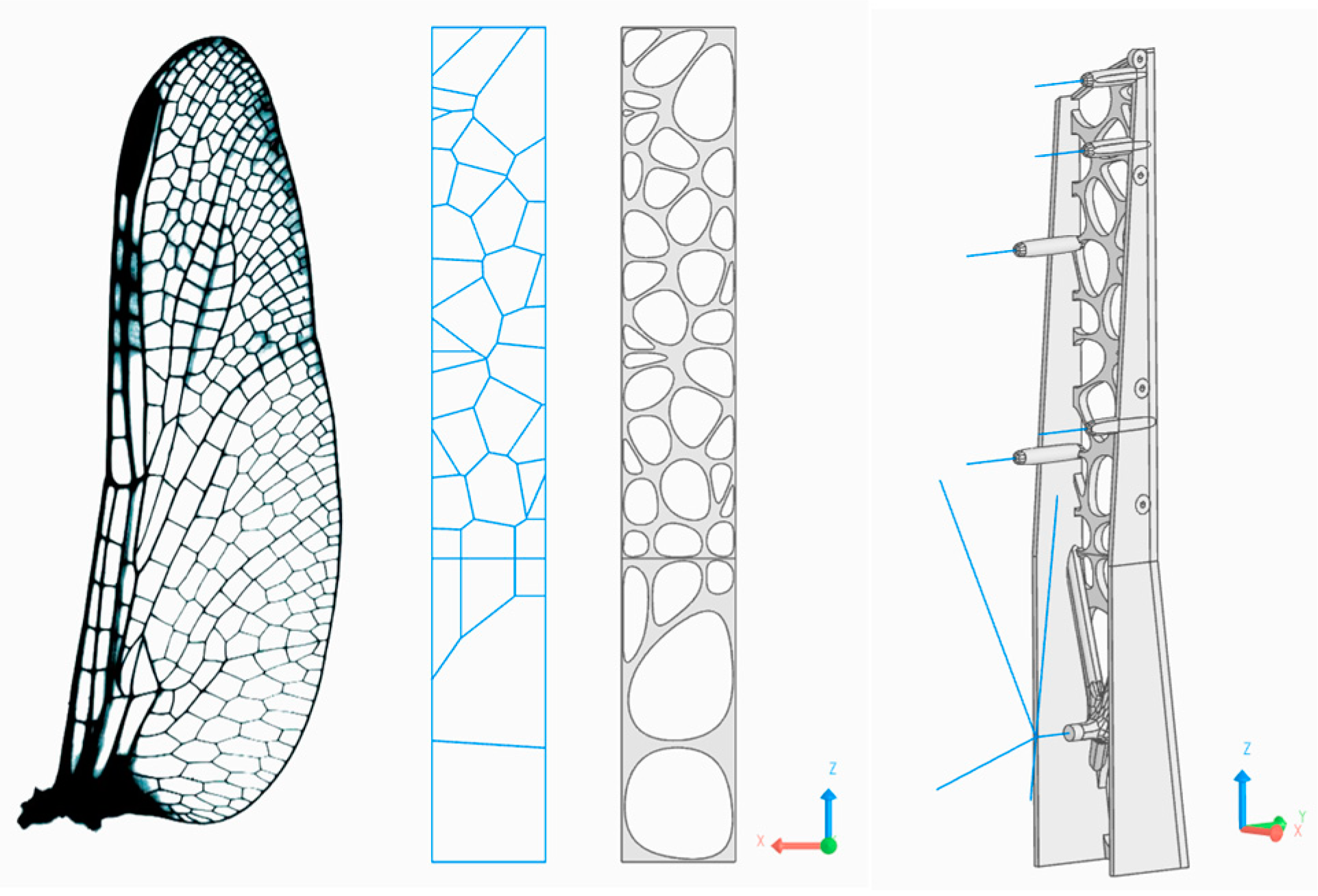
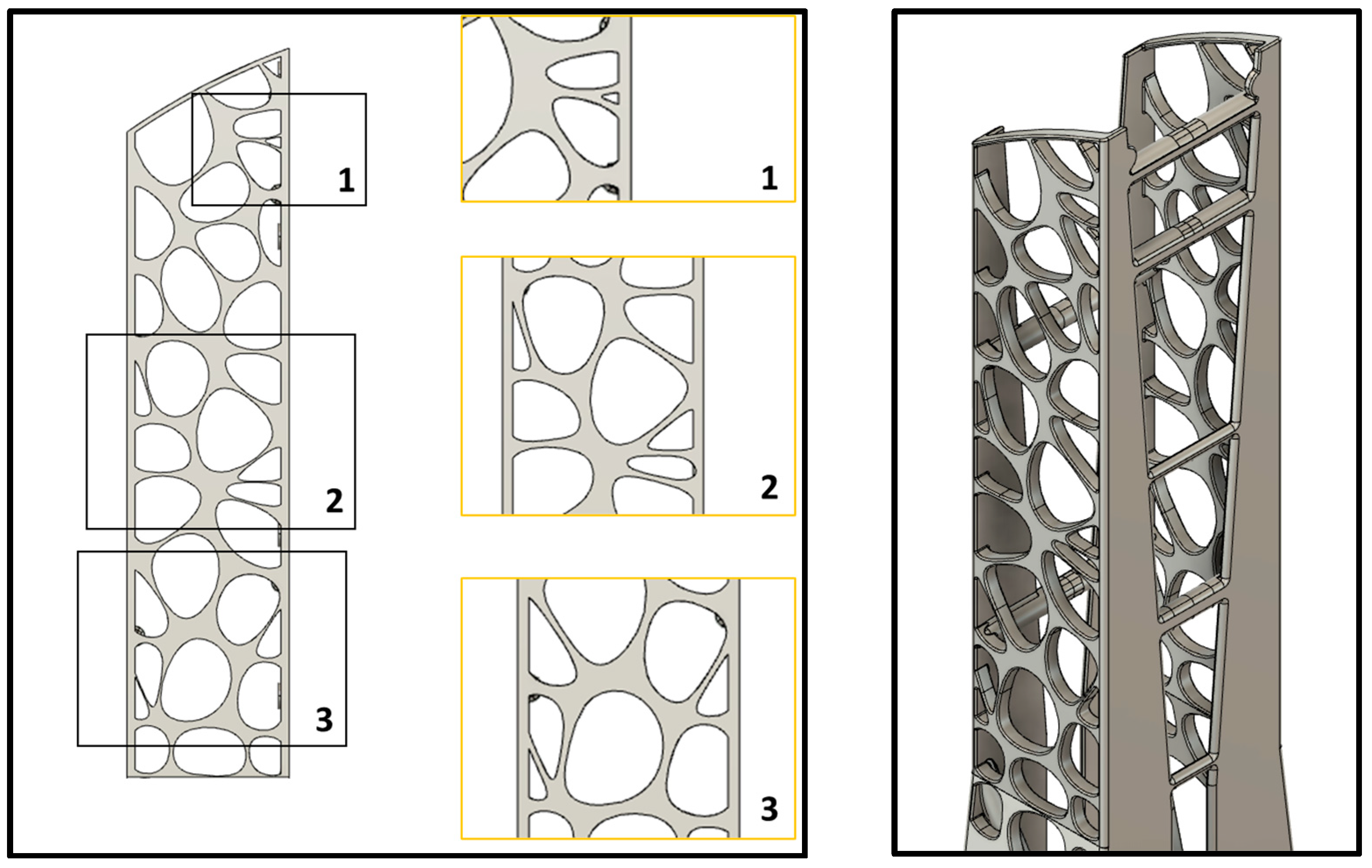
The Voronoi pattern is also based on topology optimization results but is applied based on the voids appearing in the extracted load lines; see
Figure 9. The Voronoi option was selected based on its similarity to the dragonfly wing structure which flaps its wings at 32.3 Hz during hover flight and has a first vibration mode of 154 Hz—4.8 times higher—potentially providing greater stiffness and raising the first vibrational mode [
43]. In this design, reinforcement was achieved through the incorporation of skeleton-based features, which were strategically aligned with the internal load lines of the structure for optimal stability. The optimization parameters were carefully chosen to include the thickness of the Voronoi cell separations and the thickness of the walls themselves, along with the diameter of the skeleton elements. The selection of the final design was informed by a detailed analysis of stress and deformation, as well as the first eigenfrequency results for these specified parameters, ensuring a design that is both structurally sound and efficient.
These two outcomes are referred to as Skeleton design and Voronoi design, respectively. Both can be seen in
Figure 10.
5. Results
To perform the structural analysis of all outcomes, ANSYS Workbench 2020 software has been chosen. In this way, convergent conclusions are obtained due to the use of the same software for each solution. In the
Table 2, the values of all the relevant factors are summarized.
6. Discussion
Table 2 shows the results of the modal and static-structural analyses performed on each of the designs. The reference design stands out for being the heaviest (344.76 kg) due to being the already existing one built with structural steel. In addition, the Skeleton design outcome stands out for being the lightest (85.23 kg).
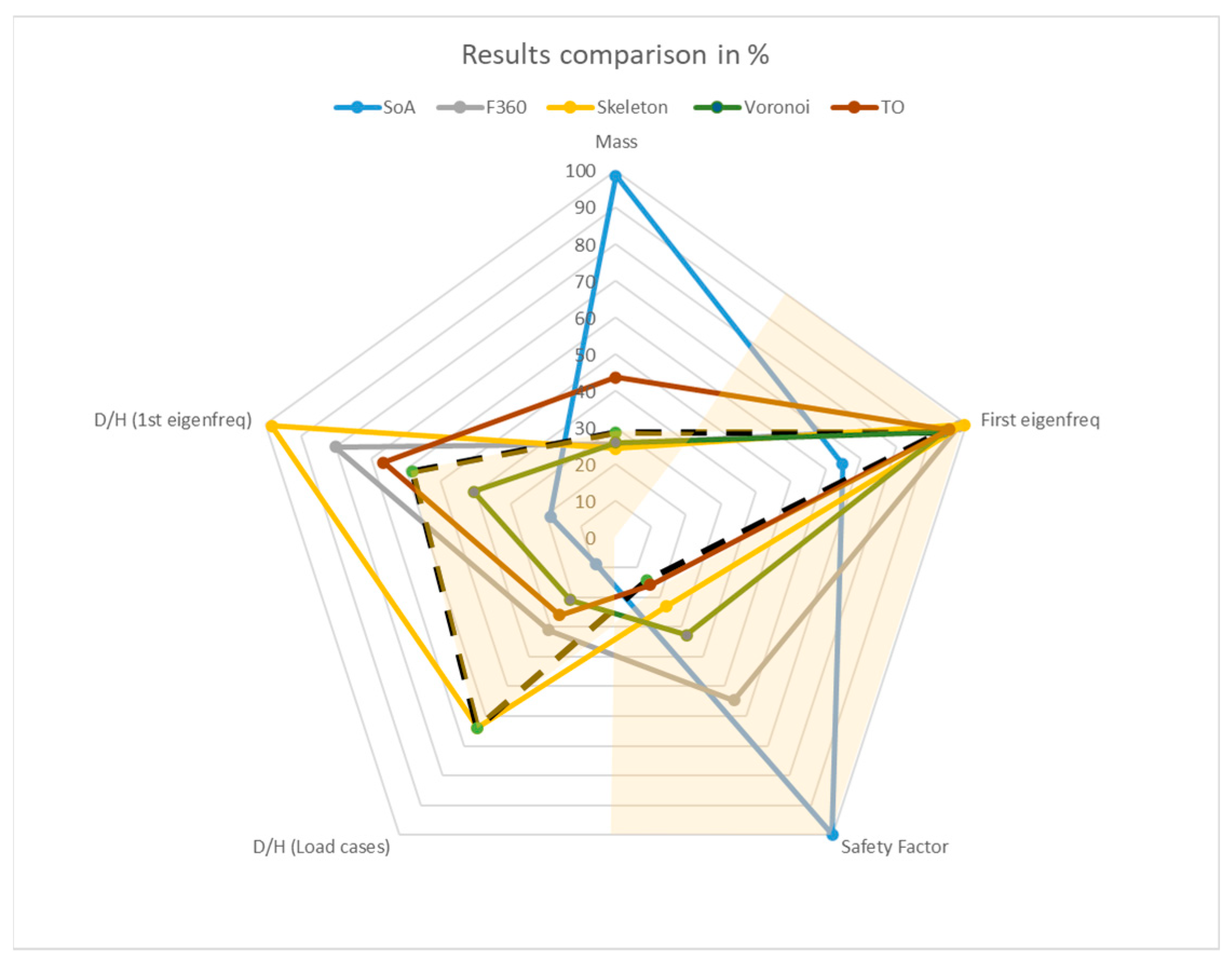
Figure 11 compares the values of each of the five factors that determine the quality of the design divided by the maximum so that the graph is on a common percentage scale. The five factors that best define a successful design are mass, first natural frequency, Von Mises maximum stress safety factor, the maximum deformation ratio to total height of the structure for the load cases, and the same ratio for the resonance at the first natural frequency. The limit of each of these factors has been drawn (black dashed line) which the values cannot fall below or exceed depending on the magnitude being looked at. Therefore, the area shaded in yellow represents the areas where the design happens to be within acceptable margins.
Mass: 100 kg to reduce the mass to 30% of the reference design. If the design is lighter than this limit; it would be accepted.
First eigenfrequency: Minimum first natural frequency of 60 Hz. All the designs with a lower value are rejected.
Safety factor: Limit of a minimum safety factor 40 as a sufficiently laudable value for tooling structures. Values below this limit are rejected.
Deformation to height ratio: Two different values for two different studies, one for the load cases (operational and structural) and other for the case of resonance. The limit was set to a value a bit bigger than the average of all, so the most deviated deformations are discarded. Thus, the results above those limits are rejected.
Looking at the results concerning mass, it can be seen that two of the five designs are outside the acceptable area. That is, the reference (344.76 kg) and the TO (153.05 kg) would be discarded. The F360 (89.08 kg), the skeleton design (85,225 kg), and the Voronoi design (90.61 kg) would be inside the margin. Regarding the first vibrational mode, being a factor of great importance in the acceptance of the designs, all designs achieved the established limit. The same occurs with the safety factor and the deformation-to-height ratio when supporting the load cases. Up to this point, based on mass criteria, two designs would have been discarded. Finally, observing the ratio of deformation per height of the structure for the first eigenfrequency, it can be seen that the F360 outcome and the skeleton results are outside the limit. The highest deformation was found for the Skeleton design and the F360 outcome, which a priori in terms of mass and structural characteristics seemed to be the best results obtained in this study.
The Voronoi-based design, situated uniquely within the defined margins, exhibits superior deformation characteristics in comparison to other designs. Significative enhancements in deformation behavior are observed across both scenarios—the first eigenfrequency and various load cases—distinguishing it as the second-best performer in the latter and the optimal choice under resonance, with the exception of the reference design, as can be observed in
Figure 11 and
Figure 12. This finding suggests that, analogous to the structural attributes observed in dragonfly wings [
43], Voronoi structures—as the results demonstrate—show a remarkable stiffness, surpassing even designs explicitly tailored to fulfill precise vibrational criteria.
In the realm of bioinspired design, understanding the long-term durability and resilience of structures under repetitive stress conditions is of great importance. This is particularly true for this study, where the goal is to optimize aeronautical tooling using bioinspired methods. To this end, a comprehensive fatigue analysis was incorporated into this research. This analysis is focused on the selected design, which, although generally exhibiting non-significant stress levels under standard operating conditions, may still benefit from a detailed evaluation of its fatigue properties. By examining the fatigue behavior of the selected bioinspired design, it is intended to provide a deeper insight on how the outcome is far from failure, which is of great importance in this kind of application.
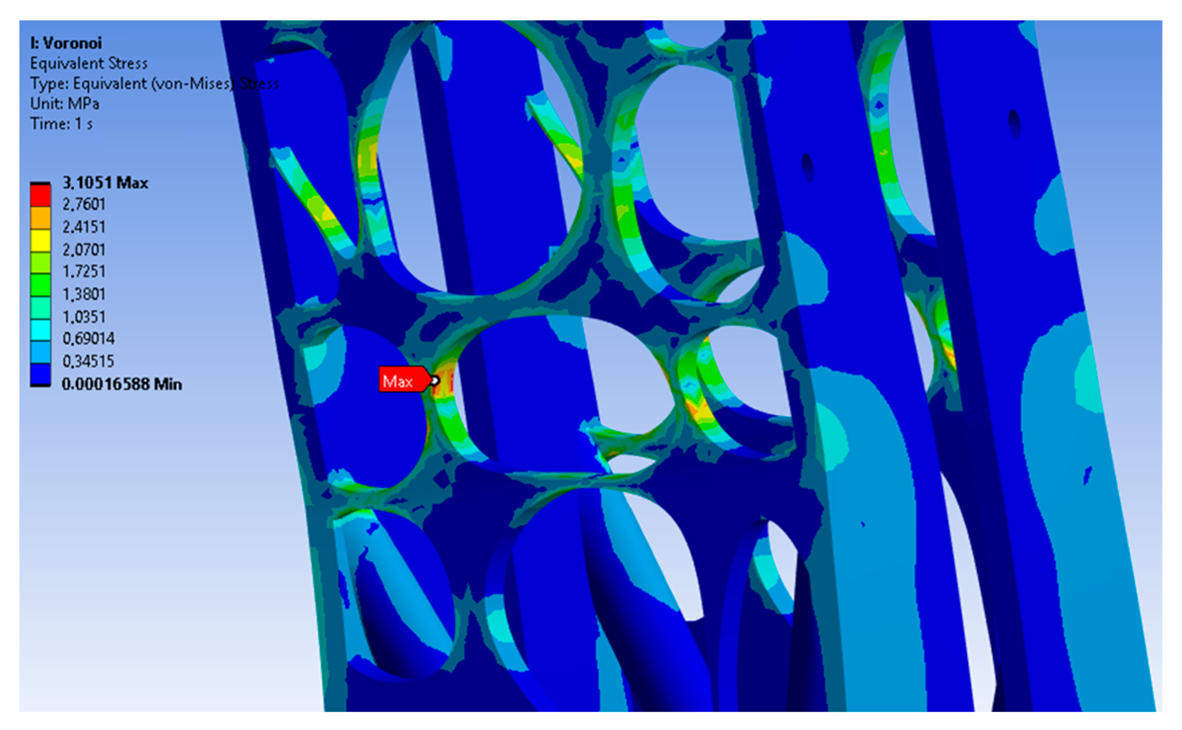
The first step is to check which are the maximum and minimum stress values under the worst cases presented before. In this particular case, the maximum Von Mises equivalent stress is going to be the criteria to define the amplitude of the cyclic loading. The equivalent Von Mises stress is considered as a conservative method since it does not take into account the sign of the stress [
44]. However, this case needs to be conservative for its application. As seen in
Figure 13, the maximum Von Mises values for the worst case (loads of part weight and operations applied) is 3.1051 MPa and the minimum is 0 MPa.
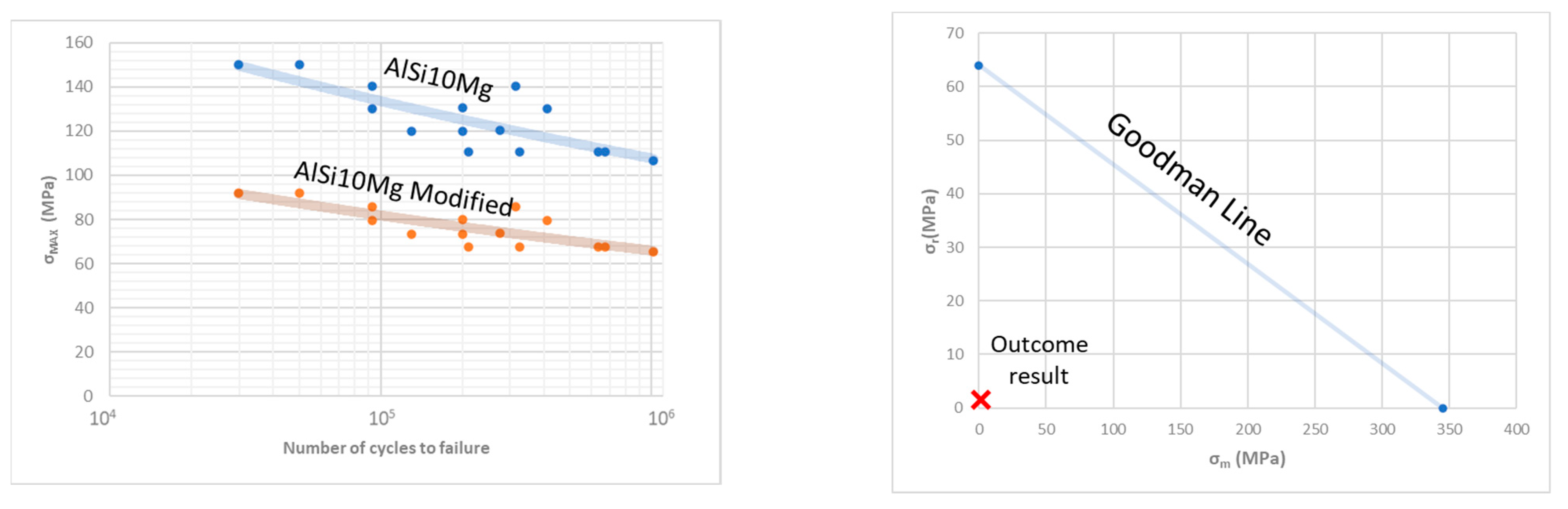
To study fatigue, the graphic from [
45] has to be modified since the fatigue criteria are prepared for rotary samples and not axial tension samples. The modifying parameters for aluminum alloys are given by [
46].
where
is the modified fatigue limit and
is the stress for the rotary sample and
where
is the stress value for the axial alternating stress sample [
47].
is defined by:
where
is known as the fatigue notch coefficient,
is the surface quality factor, and
is the size factor. Both
and
are taken from empirical equations [
48];
is supposed to be 1 as a first approach, while
depends on the UTS of the material and the surface roughness. In this case, the structure would be a ground surface, so the coefficient is 0.961 for AlSi110 Mg.
depends on
, notch sensitivity, and
, the stress concentration factor.
for aluminum alloys is 0.483 [
18] and
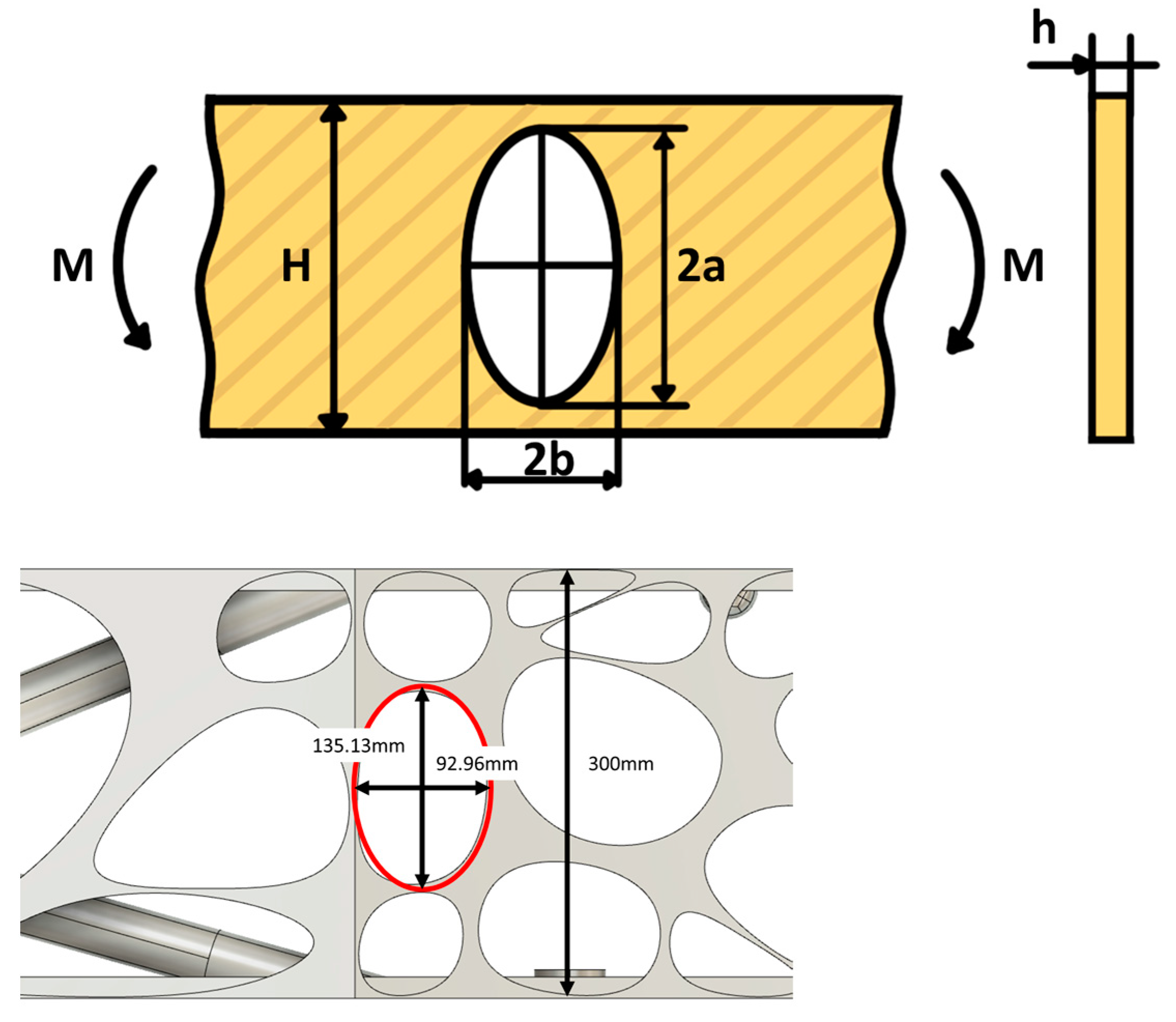
is defined by the problem studied. For the purpose of calculating the stress concentration factor (
), the case study was simplified to represent the bending of a plate with an elliptical hole. This simplification serves as a proxy for the more complex geometries observed at the sides of the Voronoi structure, as seen in
Figure 14 [
49].
Once all the correction parameters are defined, the new S-N curve for the AlSi10Mg alloy is given in the next figure.
The fatigue is analyzed for 10
6 cycles and with the Goodman criteria, as can be seen in
Figure 15. As predicted, with the load case studied here, the outcome is far from the Goodman line, which means that it is far from failure because of fatigue.
7. Design Validation
After conducting a design review based on the structural analysis performed, the Voronoi design was determined to be the best option. The manufacturing process was then investigated and it was decided to use AM assisted casting, which involves manufacturing the sand mold for casting using binder jetting technology. While the design of the filling and feeding systems for casting will not be discussed in detail in this paper due to its depth, it is important to note that the design was validated through casting simulation using ProCast software from ESI Group. The design had to be partially modified to be correctly casted. There were two constraints to be considered: a minimum thickness of 7 mm and to round all the sharp edges. Some ribs inside the Voronoi pattern needed to be modified, but the rest of the pattern was suitable for casting as seen in
Figure 16. The geometrical changes did not change significantly, nor the weight, nor the structural behavior of the component.
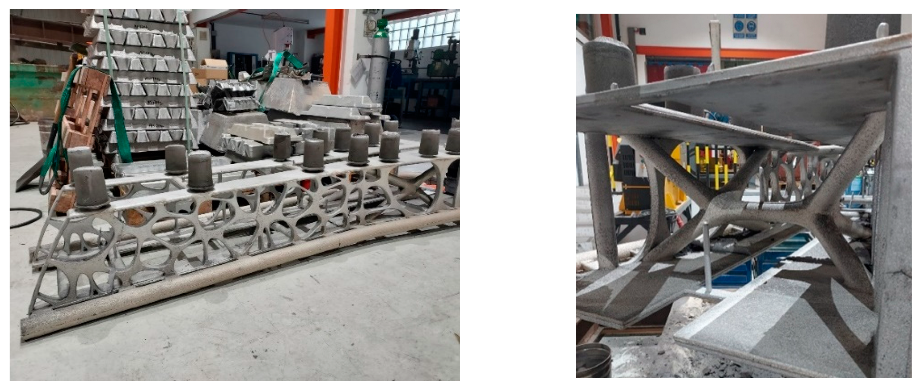
The casting was successfully performed (
Figure 17) using an AlSi10Mg alloy, which has been proven to be a reliable alloy for casting [
50].
To validate the design and manufacturing process, a modal test was conducted with the goal of ensuring that the first eigenfrequency of the structure was higher as supposed. A free vibration configuration was selected for this test in order to achieve maximum realism. In this study, a distinction between the configurations used in the FEA must be noted. The configuration employed for the FEA in the discussion section differs from that of the free vibration analysis. Due to the complexities associated with achieving perfect clamping of the structure, as assumed in the FEA for the discussion, the study opted for free vibration as a more practical configuration for validation purposes. Consequently, a supplementary FEA was conducted under this new configuration to ensure that the results were comparable and reliable. The structure was suspended from a crane using elastic ropes with negligible stiffness compared to that of the alloy (
Figure 18). The acquisition device was an ICP 356A15 triaxial accelerometer of PCB and the impact device a 086C03 impulse force hammer of PCB. The impacts were performed in 20 different points in two directions. Those points were taken in 5 different heights so the different modes were noticed. In total, 40 runs were obtained.
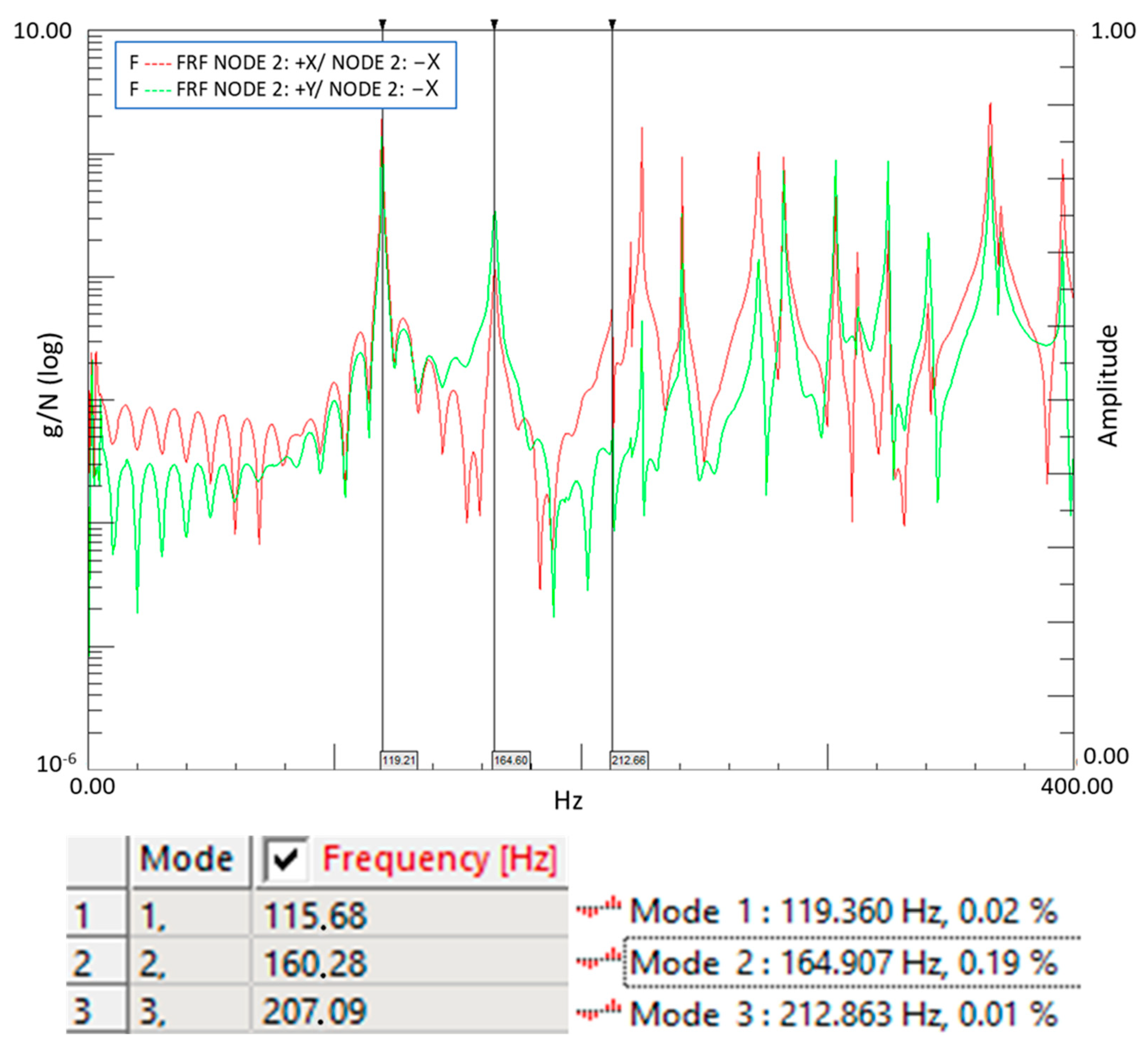
The results of this test are shown in
Figure 19. In order to compare these results with those obtained from finite element analysis, a free vibration FEA simulation was also performed using default aluminum alloy properties from ANSYS engineering data. The results showed a relative deviation, which may have been due to differences between the properties of the actual alloy used and those of ANSYS’s default aluminum alloy properties. The modal testing data were analyzed with Siemens Simcenter Testlab.
To obtain more accurate results, samples were taken from the casting and their density was evaluated using an Archimedes balance. Finally, Young’s modulus was corrected based on mathematical development [
51] in order to obtain more reliable results. The final results are shown in
Table 3. The first three modes of the experimental and corrected Young’s modulus FEA were in free vibration configuration.
Figure 19.
The FRF of the signal from one of the acquisition nodes in two directions X and Y (Up). The results comparison of the generic material properties selected for the FEA (left) and the results of the modal test (right) (Down).
Figure 19.
The FRF of the signal from one of the acquisition nodes in two directions X and Y (Up). The results comparison of the generic material properties selected for the FEA (left) and the results of the modal test (right) (Down).
8. Conclusions
In this study, three different bioinspired design methods were selected and applied to a common use case: an aeronautic tooling that needed to be lightened and functionality directed optimized. The selection of these methods was made in order to have a broader study that included more classic methods such as traditional topology optimization, new emerging tools of generative design, and a novel method that mixed different bioinspired design methods. Four designs were evaluated in addition to the base design or reference design. As an overall conclusion, it can be said that all four bioinspired designs improved upon the reference design in some way. This demonstrates that mimicking nature in its different forms can be beneficial for improving upon what a human engineer can come up with based on their knowledge and experience. The findings of this study indicate that a hybrid approach, integrating simulation-driven design with true biomimicry, leads to a significant 74% reduction in mass and an enhanced first vibrational mode, effectively preventing resonance in aeronautical assembly operations. Additionally, the proposed bioinspired designs demonstrate their capability to withstand operational loads within an acceptable safety factor margin, highlighting their potential as a transformative solution in structural engineering. These results suggest that the efficacy of this hybrid method merits further investigation in diverse structural engineering applications.
The importance of design validation cannot be overstated. In this study, the digital models were compared with reality to ensure their accuracy. The first challenge in this process was the manufacturing process. To ensure the correct filling of the part, pertinent simulations were performed. All of this resulted in a high-quality casting. This has been a major milestone and nothing similar has been found with this kind of design in terms of manufacturing process and size. To certify the good result, intensive modal testing was performed. The results of this study showed that the work proceeded as planned and all challenges faced in this project were successfully overcome. This represents a significant achievement in the field of bioinspired design.
Based on this study, the successful application of bioinspired design methodologies to an aeronautic tooling represents a significant achievement for structural engineering in various industries such as aerospace, automotive, and energy generation. The potential for lightweight, functionality-aimed, and manufacturable metallic components using bioinspired design is immense. In the aerospace industry, for example, the reduction of mass in aircraft components can lead to significant fuel savings and enhance new propulsion methods. In the automotive industry, lighter vehicles can improve fuel efficiency, electric vehicle range, and performance. In the energy-generation industry, lighter and more efficient components can improve the performance and longevity of power-generation equipment. The next steps for future research in this field should include further evaluation of the hybrid method of simulation-driven design and true biomimicry, as well as the exploration of other bioinspired design methodologies. Additionally, the manufacturing process and its potential for producing complex structures should be further investigated in terms of cost and environmental impact.
In conclusion, this study has demonstrated the potential of bioinspired design to improve upon traditional engineering methods and achieve significant advancements in structural engineering. Mimicking directly from nature can still be a powerful method, as proven in this study.

 ,
, 


