Abstract
The work is new due to the type of process used—ultrasonic precision machining—to determine the possible effect of spindle heating (long-term machining) on the precision of the flat surface. It was carried out on a precise ultrasonic machining machine, and the material of workpiece was ceramic Al2O3. A flat surface was machined. Such an experiment has not been feasible until now. The experiment was divided into two days. On the first day, the machining time was 4 h. It is a long enough time to create a temperature-steady state. On the second day, with a cold tool and cold machine tool, we continued where we left off on the first day. This is how we monitored the accuracy of the dimensions of the workpiece on the plane surface. We have achieved the following: The average interface depth achieved values of 0.007089 mm and 0.003667 mm for cold and heated spindles, respectively. It means that when the spindle is not heated, the depth of the interface is higher by 93% (almost double the depth). The average standard deviation of the interface depth is 0.001683 mm and 0.000997 mm for cold and heated spindles, respectively. It means that when the spindle is not heated, the process is not as stable, and the standard deviation is higher by 69%.
1. Introduction
Finishing machining methods can be included among the methods referred to as microtechnologies and nanotechnologies. These terms also mean production technologies that achieve dimensional accuracy in micrometers or in nanometers. In both cases (micro- and nanotechnologies), there are basically two ways to proceed. It is either the removal of the relevant surface layer or the addition (e.g., coating) of a surface layer in the specified dimensional ratios. The goal of finishing machining is to improve the shape, dimensions, and quality of the surface. As a rule, we only remove small particles of material during finishing. These impose a small cutting resistance, cause only low deformations of the workpiece, the tool, and the machine tool, and thus guarantee high accuracy of the workpiece. The achieved surface roughness is usually very low, less than Ra = 0.8 μm. The finished surface has a high quality, even appearance, and sometimes it is even mirror-glossy, which is not always necessary because the surface obtained by fine scoring (of course also after finishing) holds the so-called lubricating film better, which reduces the friction and wear of such movingly contacting surfaces when they are used in machinery [1]. Accuracy is determined by deviations from the ideal value of the selected variable. Deviations from the ideal value are inaccuracies. In the case of precise technologies, these are physical, geometric quantities. Objects with precisely determined dimensions do not exist. The exact dimension is zero deviation from the specified measure. How much is zero deviation? Tenth, hundredth, thousandth of a millimeter? And there is also a tenth, a hundredth, a thousandth of a micrometer, so we can continue ad infinitum. There are only dimensions that fall within a certain selected tolerance, which are smaller than the largest permissible deviation. We consider such dimensions to be accurate. Precision is basically a session (relationship). If the dimension is from the specified interval, we consider it to be accurate. So, accuracy is a human concept. Accuracy is how close a value is to its true value. Precision is how repeatable a measurement is.
The following are known physical causes of inaccuracy in the dimensions of engineering components [2]:
- -
- Geometric inaccuracies of the used means, machines, tools, and preparations. They are inaccuracies of dimensions and shapes such as flatness, cylindricity, conicity, perpendicularity, deviations from the paraboloid, hyperboloid, deviations from the involute, etc.
- -
- Arbitrary inhomogeneity of the workpiece, e.g., chemical composition, structure, existence of voltage, temperature, electric, ultrasonic, or other fields.
- -
- Static or dynamic deviations of the desired relative position of the material (piece) and the cutting edge of the tool in the machine’s coordinate system. For example, mistakes, lack of definition of moving parts, the vibration of a member of the system, or transmission from the surroundings.
- -
- Loss of geometric shape (deformation) of members of the work system due to technological forces, heat, and erosion (wear and tear—loss of particles).
- -
- Deformations of the workpiece due to the release of internal stresses and the action of external forces. Internal stresses can be released by material removal, structural changes, removal, etc.
How do we make precision parts? We produce precise parts when the causes of inaccuracies are eliminated to such an extent that the shape, dimensional, and positional deviations of the elements (elements) of the product—parts—are within the specified limits (tolerances). It is not always technically and economically possible.
There are many studies and contributions that address the issue of precision in machining. We have selected some publications so that they form a broad mosaic of the presented issues.
One of the reasons machined surfaces occur out of flatness when milling is cutting tool deflection affected by cutting force and low stiffness of the machine tool. This issue was proposed to be solved via offline tool path compensation, a semiempirical model based on Armarero theory, and a machine tool deflection model [3]. Utilizing ultrasonic-vibration-assisted technology in the finishing operations is a perspective technique for ensuring high geometrical accuracy and machined surface roughness [4]. It was reported that the roughness of the machined surface is significantly improved by ultrasonic-vibration-assisted (UVA) ball polishing from 0.122 µm to 0.022 µm [5,6]. The physical nature of UVA machining’s positive effect on machined surface morphology is based on the reduction in frictional force [7]. Though cutting speed and feed have affected surface roughness, the amplitude of ultrasonic vibrations during UVA milling appears to be more significant [8,9]. The positive effect of UVA technology on surface roughness and surface crack reduction can be improved with the MQL technique [7,10,11]. Structural and motional errors of CNC machines play an essential role in ensuring machined surface accuracy. Jaskolski et al. specified that surface flatness and vertical parallelism deviation, which were measured by a 3D scanner, are significantly affected by machine tools [12]. Combining 3D scanning with the reverse engineering technique CAD model [13] shows good reliability in evaluating machined surfaces’ shape and size deviations [14]. However, it should be considered that CAD model continuity affects accuracy when machining curvy surfaces, namely B-spline and Bezier curves. In practice, CAD model continuity leads to a surface deviation that can vary up to 60 µm but does not affect surface roughness [15]. Dong et al. reported that the surface roughness of the freeform surface when milling is greatly influenced by the bull-nose mill’s local inclination angle and tilt angle [16]. Though 3D scanning is a reliable measuring method, it requires expensive equipment. As an alternative measuring technique for tool geometry accuracy monitoring, it was proposed to use a trigger touch probe integrated into the NC control system [17] or laser measuring tools or interferometers to control angular errors, horizontal and vertical straightness errors, parallelism errors [18], and squareness errors [19]. Another way to affect and improve machining accuracy is to predict feed rate and cycle times considering interpolator dynamics using a finite impulse response-based low pass filter, which estimated more than 90% more accurate cycle times than CAM-based prediction [20]. Holub et al. found that the roundness of the machined surface when milling on a CNC machine can be improved by 40% using volumetric compensation accompanied by a LaserTRACER self-tracking interferometer [21]. Lu et al. proposed a multibody system (MBS) error model used for the identification of total geometric errors, which were encountered through value-leaded global sensitivity analysis and considered in the Beckhoff TwinCAT servo system for the compensation straightness error model using the B-spline interpolation method [22]. As a result, geometric error in the X direction of CNC machine movement was significantly reduced; however, the proposed compensation model did not consider the effect of cutting parameters and thermal expansion of CNC machine units, as well as cutting tool thermal expansion [23,24]. However, Zhao et al. found that the thermal elongation of the cutting tool during the warming-up of a machine tool can reach up to 130 µm in the axial direction [25]. These findings were proved with finite element modeling (FEM) in Ansys software based on measuring spindle unit temperature with thermocouple sensors. Heating spindle parts up to 78 °C explains the thermal elongation of CNC milling machine spindle unit, though this temperature can be reduced by cooling system up to 16 °C [26]. Another sensor-based study of machine tool units reported about 45 °C and thermal error of up to 75 µm [27]. The effects of major heat sources such as ambient temperature changes, the spindle rotation, and X, Y, and Z feed drive activities were also considered for evaluating the five axes of the CNC milling center unites deformation model. Based on the multiple linear regression (MLR) model for the Python code-based software compensation of CNC milling center unit thermal displacements, the thermal errors were reduced up to 62%, 56%, and 73% in the X, Y, and Z directions, respectively [28]. A feature study of technological parameters’ effect on dimensional accuracy and surface quality when milling on a CNC machine assumed that increasing cutting speed causes an increased scatter of size dimension. In contrast, increased feed per tooth reduces deviation from the nominal size [29]. The scatter of size dimensions can occur because of the relatively low stiffness of machine units under certain cutting parameters, leading to chatter vibrations and poor surface quality. Rock proposed to predict regenerative chatter with hardware-in-the-loop simulation using a dexel-based cutting model. However, an experimental study did not validate this model [30]. One of the possible ways to reduce chatter vibrations is using digital twin technology, which was implemented by combining the machined part CAD model and probing cycle during milling [31] with feature optimization of cutting parameters and error compensation [32]. The reliable method of machining error compensation when machining curve surfaces can be utilized in the prediction of counter error based on model identification and kinematic analysis of machine tool, which allow for reducing counter error for 61% up to 3µm [33]. Yeh et al. show that the cycle-based iterative learning contour control method implemented through permanent magnet synchronous motor (PMSM) driving control ensures an 80% contour error reduction rate in comparison with the proportional–integral control [34,35]. It was proposed to implement optimization based on multiobjective parameters for the machining process’s high efficiency and energy saving. Considering machine performance, tool life, and machining process requirements, the multiobjective generic algorithm was carried out to solve the Pareto solution of the target model. As a result, optimal cutting parameters for roughing and semi-finishing milling were defined [36]. For the last few years, the artificial intelligence method has found its application as a deep learning technique for evaluating surface accuracy and quality when machining. The combination of the Gramian angular field (GAF) and trained convolutional neural network (CNN) model showed good results in predicting machining conditions. The GAF allowed the transfer of CNC machine control system signals in images of the machined surface, which proceeded with the CNN algorithm. The trained classification CNN model resulted in recall, precision, and accuracy with 75%, 88%, and 94% values, respectively, for predicting workpiece surface quality and tool breakage [37] and tool life [38]. Currently, different types of tool wear can be predicted using artificial neuron networks and measured in real time. For that purpose, complex sensor systems that measure acoustic emission and acceleration are developed [39].
Though the effect of heat generation in the machine tool units is known and studied, there are very few researches that correspond to the influence of machine tool thermal expansion on the accuracy and surface roughness of the machined surface. The current paper is focused on the experimental study of the technology of milling a planar surface on a precision CNC ultrasonic machine using a typical ultrasonic tool (described below). The influence of the thermal load on some parts of the machine tool, the ultrasonic tool, and the workpiece from the heat generated in the machine’s moving parts and from the cutting process itself was investigated. This generated heat then affected the accuracy of the produced planar surface, as documented below.
2. Materials and Methods
We called the experiment as follows: the spindle temperature influence on topological precision during rotary ultrasonic machining of ceramic material.
2.1. The Machine Tool
The research was implemented on the machine tool Ultrasonic 20 linear (Figure 1). It is a high-precision five-rotary ultrasonic machine. It is produced by the German company DMG Mori Seiki. This machine can control five axes continuously, and therefore, it can machine complex shapes in one clamping. In Table 1 and Table 2, the selected technical parameters of the machine tool Ultrasonic 20 linear are listed.
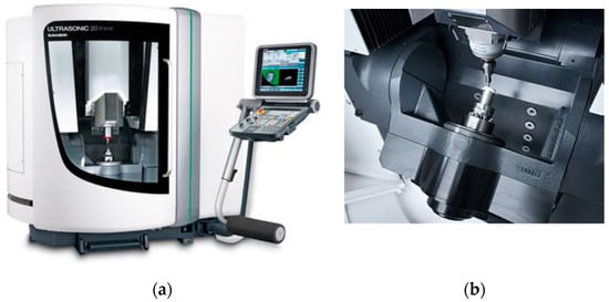
Figure 1.
Ultrasonic 20 linear: (a) machine tool and (b) workplace of machine.

Table 1.
Characteristics of table of the ultrasonic five-axis machine, Ultrasonic 20 linear.
Table 2.
Characteristics of spindle, tool, clamping system of the ultrasonic five-axis machine, Ultrasonic 20 linear.
This machine can continuously control five axes and machine complex shapes in one clamping. The tool performs all three linear movements (X, Y, and Z). The workpiece performs two remaining rotational movements (A and C). Rotation around the X-axis (A) is ensured by the cradle construction. Rotation around the Z-axis (C) is ensured by the rotary table. It could be used for precision and micromachining. This machine deploys the spindle USB 40. The high spindle speed is usually not used for high-speed machining (HSC) [40,41], but more often, it is used for micromachining, where tools with small diameters are used, and to reach proper cutting speed, the high spindle speed is required. The machine utilizes an ultrasonic generator, USG2000. Conversion of electric energy to mechanical energy is provided by the piezo-ceramic transducer. To achieve such high accuracy of machining, extreme precision of measurements of the tool dimensions is required. Laser measurement device BLUM Laser P87 serves ideally for this purpose. Tough probe Reinshaw OMP 400 is utilized for the measurement of the workpieces. This probe has a ruby tip. Removing of chips is ensured by the cooling device Sauer KMA 300. As a coolant, a mixture of oil and water is used. As oil, Sintilo 9918 by Castrol company is utilized. This oil is diluted by pure water. The recommended concentration of oil in water varies from 4 to 8%. This emulsion is fed by the core of the tool (inner cooling) and/or by four outer nozzles (outer cooling). This machine could be programmed manually by Siemens 840D Solutionline control system or by CAD/CAM software, such as PowerShape and PowerMill. This machine tool has a length of 2020 mm, a width of 2196 mm, and a height of 2385 mm, and its weight is 3750 kg. The machine tool and its workplace are shown in Figure 1. It is situated in the Centre of Excellence of 5-Axis Machining (CE5AM) at MTF STU in Trnava.
2.2. The Cutting Tool
An ultrasonic milling cutter with diamond abrasive made by the German company Schott Diamantwerkzeuge GmbH was used for the research. It is a face mill with the trade name Schott 858009—3.25 6A9-Da24-2-6-14h6x8,4 MES3 D46H (Figure 2). This labeling is based on the FEPA-Norm (Federation of European Producers of Abrasives). According to its label, it is obvious that this is an ultrasonic mill with a pot-like shape (cup wheel). 6A9 means that the abrasive is localized, especially on the rake face (when abrasive is localized, especially on the flank face, it carries the label 6A2). This ultrasonic mill has a diameter of 24 mm (Da24), a 2 mm thick wall, and a 6 mm high active part. Diamond grains have approx. an average size of 46 μm with high quality (D46H), and they are bonded in metal (MES). It can be mounted by a bore (14 h 6 × 8.4) by clamping screw, allowing inner cooling. This tool will be mounted in tool-holder HSK 32 S with 14h6 tool-holder, manufactured by SAUER GmbH Ultrasonic. It is a tool holder for rotary ultrasonic tools that can be spun up to 10,000 rpm. The main characteristics of this ultrasonic tool are labeled in Table 3.
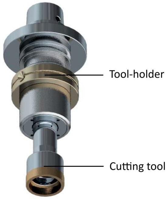
Figure 2.
Ultrasonic face mill cutting tool mounted in ultrasonic tool holder.
Table 3.
Characteristics of the ultrasonic milling cutter.
2.3. The Workpiece
As a workpiece material, alumina (Al2O3) ceramic block with dimensions 100 × 100 × 25 mm was used. The square surface was machined. Erowa vice was used as a fixature. It is a precise and reliable clamping device, ideal for industrial applications. There were parallel sides of the workpiece for used clamping.
2.4. The Cutting Conditions
An ultrasonic milling cutter with a diameter of 24 mm was used as a cutting tool. There were set following cutting parameters: axial depth of cut (ap) 0.02 mm, radial depth of cut (ae) 50% (12 mm), cutting speed (vc) 400 m/min, feed rate (vf) 1000 mm/min, see Table 4.
Table 4.
Cutting parameters.
Water emulsion with 6% oil was used as a coolant. Its temperature was room temperature, e.g., 22 °C. The purpose of the coolant is more for tool cleaning than for decreasing the cutting temperature.
2.5. The Strategy of Machining
The experiment was divided into several phases (see Table 5). In the first phase, the spindle with a mounted tool was heated for 4 h. Then, the machining process begins and lasts for another 4 h. The process ended approximately in the middle of the machined square surface. The final temperature of the spindle was 35 °C. After machining, the third phase begins, which consists of the spindle cooling for 16 h, and then starts a new machining process with the very same machining parameters, however, without any heating of the spindle. This machining process lasts only for a few seconds because only half of the square surface was machined (to avoid any significant heating of the spindle). The final temperature of the spindle was 23 °C.
Table 5.
Phases of experiment.
We can see the reason for adopting this processing strategy in the fact that the experiment compared surfaces processed with a heated spindle and a cold spindle. Therefore, we need to ensure that the spindle reaches working temperature (8 h should be long enough) because we need to ensure that the spindle does not reach working temperature the next day (16 h of cooling and a few seconds of machining should ensure it).
The raster strategy (Figure 3) was used for creating the sample, starting at the F position and moving up to the A position with a radial depth of cut 50% (12 mm). Measurements were perpendicular to the feed direction, repeated three times for every interface.
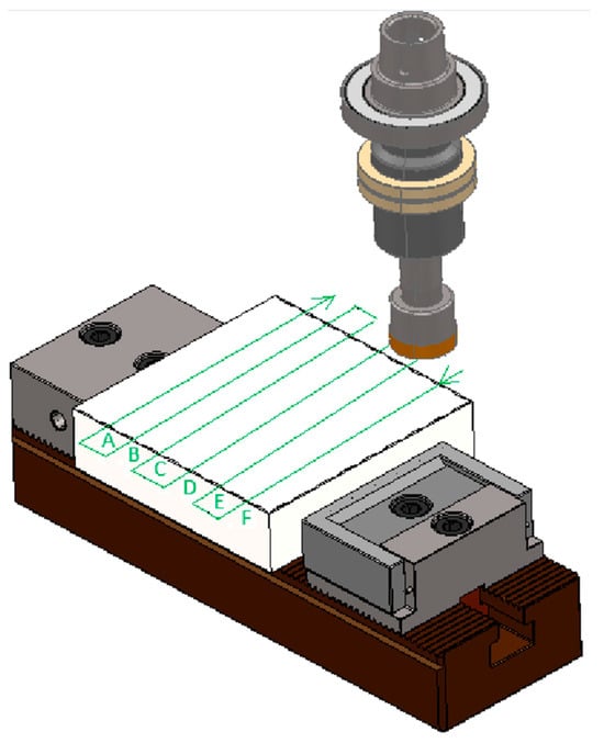
Figure 3.
Scheme of the machining procedure.
2.6. Description of the Strategy of Machining Movements Divided into Two Days
The “raster” strategy of Figure 3 was used in the experiment.
First day: In the first pass, the tool axis ran parallel to the workpiece edge, so the F interface was machined around the tool circumference.
On the second path, the tool axis moved directly above F and again moved along the interface. The tool circumference “touched” the E interface (on one side) and the right edge of the workpiece (on the other side).
Then, the tool went along E, and the tool touched D and F. Then, it went along D, and the tool touched C and E. Then, it went along C, and the tool touched B and D. Then, it went along B, and the tool touched A and C. Then, it went along A, and the tool touched the left edge of the workpiece and B interface. The position of all interfaces is shown in Figure 3.
The next day, when the spindle was already cold, the tool went along the axis of C (touch B and D), then B (touch A and C), and then also A (the left edge of the workpiece and B).
2.7. The Measurement Conditions
After the machining process, the evaluation of the machined surface began. For this purpose, the profile measuring device Surfcom 5000 was made by Accretech company (Japan). Surfcom 5000 roughmeter is regularly calibrated. The Surfcom 5000 has a contour and a roughness meter too. Profilometer Surfcom 5000, with a system of probes by Interferometer laser, has a resolution of just 0.30 nanometers. The uncertainty is as follows: Z-axis (vertical)—(± 0.2 + (H/1000)) μm, (±0.206 μm: H = 6 mm); X-axis (horizontal)—(±0.2 + (L/1000)) μm, (±0.4 μm: L = 200 mm); and the measurement resolutions of the used device are X = 0.54 nm and Z = 0.31 nm.
Measuring was held at the following conditions (Table 6): length of 80 mm, speed of 0.3 mm/s, stylus radius of 0.002 mm, temperature during measuring was 20 °C, and humidity during measurement was 60%.
Table 6.
Measurement conditions.
The scheme of the measuring process is shown in Figure 4. The letters (A–F) are labeling the interface between the tool paths (i.e., the distance between them is 12 mm). Each measurement was repeated three times at three different locations, which are labeled as y1, y2, and y3. The interfaces D, E, and F were created during the first phase of the experiment (with the heated spindle). The interfaces A, B, and C were created during the last phase of the experiment (with the cold spindle).
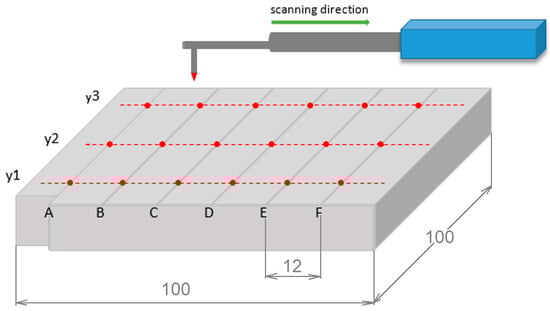
Figure 4.
Scheme of the measuring procedure. Note: The dimensions of the ceramic Al2O3 plate is 100 × 100 × 25 mm and the distance between interfaces is 12 mm.
In Figure 5, we can see a real view of the contact of the measuring probe of the Surfcom 5000 device with the machined surface.
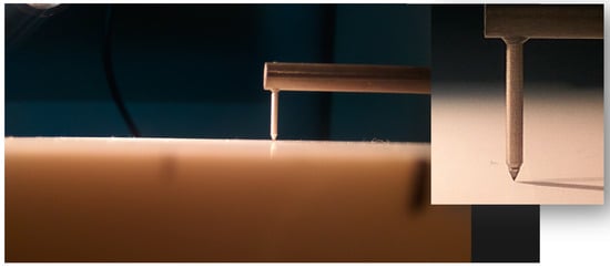
Figure 5.
A real view of the touch probe when measuring the machined surface.
3. Results
The results of the measurement are recorded in Table 7 and Figure 6. The interfaces can be seen by the naked eye. They look like shallow grooves. This table shows the depth of the interfaces at each point, the average depth for each interface, and their standard deviation. The labeling is corresponding with the one in Figure 4.
Table 7.
Profile fluctuation at interface position.
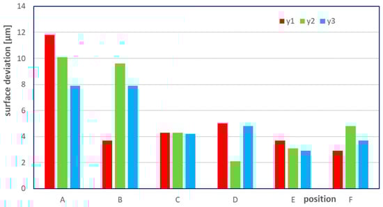
Figure 6.
A graphical representation of results.
The resultant profiles of the interfaces are shown in Figure 7. A magnification 500× was used. Those profiles correspond with the position y2.
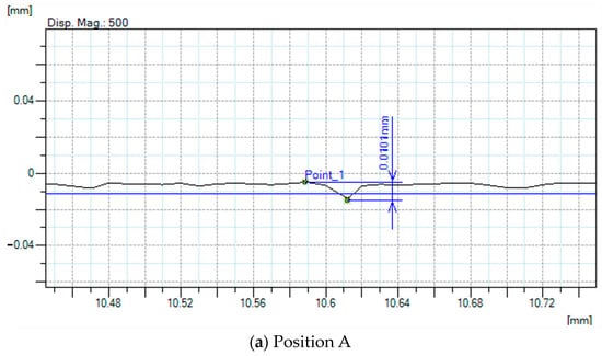
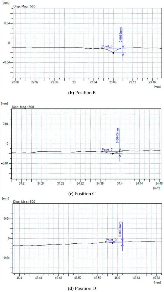
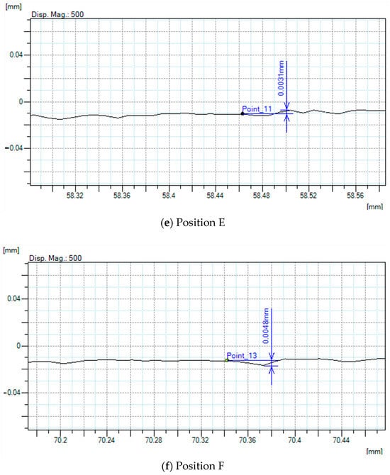
Figure 7.
The profile of the interfaces at significant positions: (a) A, (b) B, (c) C, (d) D, (e) E, and (f) F.
Figure 7 is an example of a graphical interpretation of measured contour changes in the surface in direction y2 and positions A ÷ F. The individual records are as output from the Surfcom 5000 device, locally magnified on 500×. We present profiles of the machined surface in individual locations. The value of the contribution of this image is that we can see the place of the largest deviation of the surface unevenness, where the machining finished and started the next day. Figure 7 shows interfaces between tool paths with the machined surface comparisons. It can be seen that this interface is very small but clearly identifiable.
A note on the use of the Surfcom device in measurements: Surface roughness was not measured. We measured only contours (perpendicularity distance) between the machined surfaces. Due to this, parameters Ra and Rt were not measured and evaluated.
Considering that the measured profiles can only be evaluated at high magnification because otherwise, the profiles only appear as straight lines, it is difficult to determine the change in “ap” of individual surfaces. Table 8 contains the distance of the surface in the vertical direction, but these values are indicative because the roughness of the surface already affects the determination of the value.
Table 8.
The distance of the surface in the vertical direction.
Figure 8 shows the profile for y3 at 2:1 magnification. Τhe profile at such magnification shows no changes in ap.
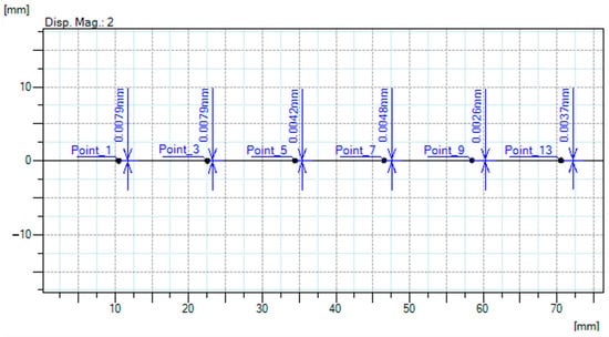
Figure 8.
The profile of the machined surface at measured position A ÷ F.
The profile changes at twice magnification (Figure 8) are very similar, which is documented in the presented measured values at individual points A ÷ F. Increasing the magnification in Figure 8 causes the shortening of the record from measuring; therefore, all analyzed points at the measured length of 80 mm will be not visible. The cutting depth “ap” in graphical interpretation cannot be highlighted in the Z-axis in ACCTeePRO software, version 5.0.15.0, because the software is causally increasing both parameters in the record.
4. Discussion
The question is as follows: does a heated spindle of a milling machine (in our case, even a machine designed for precision machining) versus a cold spindle have an effect on the machining accuracy, in our case, on the resulting profile of the planar milled surface for the ceramic material being machined? Here are some findings from our research:
4.1. Finding 1
According to the results shown in Table 7 and Figure 7, it can be concluded that the heating of the spindle has a positive effect on the resultant precision of the machined surface. The average interface depth achieved values of 7.089 μm and 3.667 μm for cold and heated spindles, respectively. It means that when spindles are not heated, the depth of the interface is higher by 93% (almost double the depth). The average standard deviation of the interface depth is 1.683 μm and 0.997 μm for cold and heated spindles, respectively. It means that when the spindle is not heated, the process is not as stable, and the standard deviation is higher by 69%.
4.2. Finding 2
According to the results presented in Table 7, it can be concluded that the average achieved values of interface depth for single-body profiles y1, y2, and y3 have the following values: for y1—5.233 μm, for y2—5.5667 μm, and for y3—5.233 μm. We can see that from this point of view, there are differences at the level of over 5 μm for all three profiles. In percentage terms with respect to profile y2, the deviation of profile y1 and profile y3 is at the level of 92.3529 percent.
4.3. Finding 3
According to the results shown in Table 7 and Figure 9, it can be concluded that the maximum is located in point A profile y1 and its value is 11.8 μm, and the minimum is located in point D profile y2, and its value is 2.1 μm. The difference between the maximum and the minimum gives us the flatness of the machined surface, the value of which is 0.0097 mm, i.e., 9.7 μm.
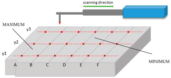
Figure 9.
Scheme of the measuring procedure and marked maximum and minimum. First day of machining, we started on track F, followed by tracks E and D. Second day of machining, we started on track C and followed tracks B and A.
4.4. Finding 4
According to the results shown in Table 7, Figure 8, and “The Description of the strategy of machining movements divided into two days”, it can be concluded that the minimum is located on the tool path—path D. At this time, the entire machining system, i.e., “machining ultrasonic machine—cutting tool—workpiece—clamping device” was found in a mutually stable temperature state. This condition occurred after a sufficiently long time of finishing machining. At the same time, the experiment was finished on the first day.
5. Conclusions
The following are results from our experiments that confirm known theoretical knowledge:
- -
- The generation of heat during machining is an accompanying phenomenon.
- -
- Heat is generated in the process of chip formation, but also in the machine tool in all moving parts of the machine tool, such as the spindle, guide surfaces, etc.
- -
- Heat is removed to colder areas. After some time, stabilization will occur.
- -
- The principle for finishing follows from the experiment and that finishing must be carried out in one shot, in one sequence, without interrupting machining.
- -
- The magnitude of the resulting inaccuracy for the machining method presented in this article will depend on many variables. The biggest variable is the machine tool itself and, above all, the accuracy of its execution with regard to temperature compensations.
Research significance is in the verification of the importance of correct heating-up of the spindle, even for such advanced technology, like rotary ultrasonic machining. This knowledge should have a positive impact on the industry because this technology is often used for achieving superior surface quality of advanced materials, and with a cold spindle, it could be difficult to reach the required surface parameters.
Author Contributions
Conceptualization, J.P., M.K., V.K., and T.V.; methodology, J.P., M.K., and P.P.; software, M.K., V.K., and T.V.; validation, J.P., M.K., V.K., and P.P.; formal analysis, M.K., J.M., and V.K.; investigation, M.K., J.M., T.V., and P.P.; resources, J.P., F.J., M.K., V.K., I.D., V.S., and T.V.; data curation, M.K., J.M., V.K., I.D., F.J., V.S., and T.V.; writing—original draft preparation, J.P., M.K., V.K., and T.V.; writing—review and editing, J.P., M.K., and V.K.; visualization, J.P., M.K., V.K., I.D., J.M., T.V., F.J., V.S. and P.P.; supervision, J.P., M.K. and V.K.; project administration, J.P. and T.V.; funding acquisition, J.P. and T.V. All authors have read and agreed to the published version of the manuscript.
Funding
This research was funded by research project APVV-21-0071 and VEGA 1/0266/23, and project: Development of new progressive cutting tools for machining parts produced by WAAM additive manufacturing technology to reduce the number of cutting tools when machining parts from different types of materials, (ITMS2014+: 313011BWQ8) supported by the Operational Programme Integrated Infrastructure funded by the European Regional Development Fund.
Data Availability Statement
Not applicable.
Conflicts of Interest
The authors declare no conflict of interest.
References
- Bekes, J.; Janac, A. Precision technology and three tendencies (in original: Presné technológie a tri tendencie). In Proceedings of the International Congress of Precision Machining, Praha, Czechoslovakia, 3–6 September 2003. [Google Scholar]
- Bekes, J. Engineering technology of metal machining. In Original: Inžinierska Technológia Obrábania Kovov; ALFA: Bratislava, Czechoslovakia, 1981. [Google Scholar]
- Checchi, A.; Costa, G.D.; Merrild, C.H.; Bissacco, G.; Hansen, H.N. Offline tool trajectory compensation for cutting forces induced errors in a portable machine tool. In Proceedings of the 17th CIRP Conference on Modelling of Machining Operations (CIRP CMMO), AMRC, Sheffield, UK, 13–14 June 2019; pp. 527–531. [Google Scholar]
- Foremny, E.; Schenck, C.; Kuhfuss, B. Integrated ultrasonic driven balancer for ultra precision high speed machine tools. In Proceedings of the 3rd International Conference on System-Integrated Intelligence—New Challenges for Product and Production Engineering (SysInt), Paderborn Univ, Heinz Nixdorf Inst, Paderborn, Germany, 13–15 June 2016; pp. 316–323. [Google Scholar]
- Shiou, F.J.; Ding, Z.L.; Lin, S.P. Reduction in the Volumetric Wear of a Ball Polishing Tool Using Ultrasonic-Vibration-Assisted Polishing Process. Lubricants 2022, 10, 339. [Google Scholar] [CrossRef]
- Nekrasov, S.; Peterka, J.; Zhyhylii, D.; Dovhopolov, A.; Kolesnyk, V. Mathematical Estimation of Roughness Rz of Threaded Surface Obtained by Machining Method. Mm Sci. J. 2022, 2022, 5699–5703. [Google Scholar] [CrossRef]
- Sonia, P.; Jain, J.K.; Saxena, K.K. Influence of ultrasonic vibration assistance in manufacturing processes: A Review. Mater. Manuf. Process. 2021, 36, 1451–1475. [Google Scholar] [CrossRef]
- Zhao, C.Y.; Wang, X.B.; Zhao, B.; Jiao, F. Microstructure of High-Performance Aluminum Alloy Surface Processed by the Single-Excitation Same-Frequency Longitudinal-Torsional Coupled Ultrasonic Vibration Milling. Materials 2018, 11, 1975. [Google Scholar] [CrossRef] [PubMed]
- Zhang, Y.M.; Zhao, B.; Wang, Y.Q.; Zhao, B.B. The stability analysis of separated feed ultrasonic milling. J. Vibroeng. 2017, 19, 1062–1073. [Google Scholar] [CrossRef][Green Version]
- Zou, Y.H.; Guo, S.J.; Li, H.Q.; Deng, X.F. Investigation on cutting performance in ultrasonic assisted helical milling of Ti6Al4V alloy by various parameters and cooling strategies. Int. J. Adv. Manuf. Technol. 2023, 126, 5123–5138. [Google Scholar] [CrossRef]
- Yi, S.C.; Qiao, G.C.; Zheng, W.; Zhou, M. Effect of crack propagation on surface formation mechanism and surface morphology evaluation of longitudinal-torsional composite ultrasonic mill grinding of Si3N4. Int. J. Adv. Manuf. Technol. 2023, 125, 5101–5117. [Google Scholar] [CrossRef]
- Jaskolski, P.; Nadolny, K.; Kukielka, K.; Kaplonek, W.; Pimenov, D.Y.; Sharma, S. Dimensional Analysis of Workpieces Machined Using Prototype Machine Tool Integrating 3D Scanning, Milling and Shaped Grinding. Materials 2020, 13, 5663. [Google Scholar] [CrossRef]
- Werner, A. Method for Enhanced Accuracy in Machining Free-Form Surfaces On Cnc Milling Machines. Acta Mech. Autom. 2022, 16, 103–110. [Google Scholar] [CrossRef]
- Martin, R.A.J.; Stephen, J.D.G.; Vinoth, A.; Muthu, E. Error analysis and point data processing of reconstructed surface by reverse engineering. In Proceedings of the 3rd International Conference on Advances in Mechanical Engineering (ICAME)/1st International Conference on Recent Advances in Composite Materials (ICRACM), Chennai, India, 24–29 February 2020. [Google Scholar]
- Kucera, D.; Linkeova, I.; Stejskal, M. The influence of CAD model continuity on accuracy and productivity of CNC machining. Int. J. Adv. Manuf. Technol. 2023, 124, 1115–1128. [Google Scholar] [CrossRef]
- Dong, J.S.; He, J.M.; Liu, S.; Wan, N.; Chang, Z.Y. A Multi-Scale Tool Orientation Generation Method for Freeform Surface Machining with Bull-Nose Tool. Micromachines 2023, 14, 1199. [Google Scholar] [CrossRef] [PubMed]
- Tang, Z.; Jiang, X.Y.; Zi, W.L.; Shen, X.; Zhang, D. Automatic Data Collecting and Application of the Touch Probing System on the CNC Machine Tool. Math. Probl. Eng. 2021, 2021, 19. [Google Scholar] [CrossRef]
- Nekrasov, S.; Zhyhylii, D.; Dovhopolov, A.; Karatas, M.A. Research on the manufacture and strength of the innovative joint of FRP machine parts. J. Manuf. Process. 2021, 72, 338–349. [Google Scholar] [CrossRef]
- Elmelegy, A.; Zahwi, S. Comparative study of error determination of machine tools. Int. J. Adv. Manuf. Technol. 2023, 124, 4575–4602. [Google Scholar] [CrossRef]
- Ward, R.; Sencer, B.; Jones, B.; Ozturk, E. Accurate prediction of machining feedrate and cycle times considering interpolator dynamics. Int. J. Adv. Manuf. Technol. 2021, 116, 417–438. [Google Scholar] [CrossRef]
- Holub, M.; Jankovych, R.; Vetiska, J.; Sramek, J.; Blecha, P.; Smolik, J.; Heinrich, P. Experimental Study of the Volumetric Error Effect on the Resulting Working Accuracy-Roundness. Appl. Sci. 2020, 10, 6233. [Google Scholar] [CrossRef]
- Lu, H.; Cheng, Q.; Zhang, X.B.; Liu, Q.; Qiao, Y.; Zhang, Y.Q. A Novel Geometric Error Compensation Method for Gantry-Moving CNC Machine Regarding Dominant Errors. Processes 2020, 8, 906. [Google Scholar] [CrossRef]
- Kolesnyk, V.; Peterka, J.; Kuruc, M.; Simna, V.; Moravcikova, J.; Vopat, T.; Lisovenko, D. Experimental Study of Drilling Temperature, Geometrical Errors and Thermal Expansion of Drill on Hole Accuracy When Drilling CFRP/Ti Alloy Stacks. Materials 2020, 13, 3232. [Google Scholar] [CrossRef]
- Soori, M. Deformation error compensation in 5-Axis milling operations of turbine blades. J. Braz. Soc. Mech. Sci. Eng. 2023, 45, 16. [Google Scholar] [CrossRef]
- Zhao, C.L.; Li, M.; Yang, J.B.; Ma, C.; Ma, Z.R. Research on the Measurement of Thermal Deformation of Tools on High-speed Machining Centers Based on Image Processing Technology. Manuf. Technol. 2022, 22, 484–493. [Google Scholar] [CrossRef]
- Dai, Y.; Li, Y.; Li, Z.L.; Wen, W.J.; Zhan, S.Q. Temperature measurement point optimization and experimental research for bi-rotary milling head of five-axis CNC machine tool. Int. J. Adv. Manuf. Technol. 2022, 121, 309–322. [Google Scholar] [CrossRef]
- Nguyen, D.K.; Huang, H.C.; Feng, T.C. Prediction of Thermal Deformation and Real-Time Error Compensation of a CNC Milling Machine in Cutting Processes. Machines 2023, 11, 248. [Google Scholar] [CrossRef]
- Mares, M.; Horejs, O.; Havlik, L. Thermal error compensation of a 5-axis machine tool using indigenous temperature sensors and CNC integrated Python code validated with a machined test piece. Precis. Eng.-J. Int. Soc. Precis. Eng. Nanotechnol. 2020, 66, 21–30. [Google Scholar] [CrossRef]
- Korpysa, J.; Kuczmaszewski, J.; Zagorski, I. Dimensional Accuracy and Surface Quality of AZ91D Magnesium Alloy Components after Precision Milling. Materials 2021, 14, 6446. [Google Scholar] [CrossRef]
- Rock, S. Predicting regenerative chatter in milling with hardware-in-the-loop simulation using a dexel-based cutting model. Prod. Eng.-Res. Dev. 2021, 15, 605–617. [Google Scholar] [CrossRef]
- Dvorak, J.; Cornelius, A.; Corson, G.; Zameroski, R.; Jacobs, L.; Penney, J.; Schmitz, T. A machining digital twin for hybrid manufacturing. Manuf. Lett. 2022, 33, 786–793. [Google Scholar] [CrossRef]
- Bhattacharyya, A.; Schmitz, T.L.; Payne, S.W.T.; Choudhury, P.R.; Schueller, J.K. Introducing engineering undergraduates to CNC machine tool error compensation. Adv. Ind. Manuf. Eng. 2022, 5, 11. [Google Scholar] [CrossRef]
- Jiang, J.L.; Li, B.R.; Lin, F.Y.; Zhang, H.; Ye, P.Q. Prediction and compensation strategy of contour error in multi-axis motion system. Int. J. Adv. Manuf. Technol. 2022, 119, 163–175. [Google Scholar] [CrossRef]
- Yeh, S.S.; Jiang, W.J. Development of Pitch Cycle-Based Iterative Learning Contour Control for Thread Milling Operations in CNC Machine Tools. Appl. Sci. 2023, 13, 6447. [Google Scholar] [CrossRef]
- Neshta, A.; Kryvoruchko, D.; Hatala, M.; Ivanov, V.; Botko, F.; Radchenko, S.; Mital, D. Technological Assurance of High-Efficiency Machining of Internal Rope Threads on Computer Numerical Control Milling Machines. J. Manuf. Sci. Eng.-Trans. Asme 2018, 140, 8. [Google Scholar] [CrossRef]
- Feng, C.H.; Guo, H.H.; Zhang, J.Y.; Huang, Y.G.; Huang, S. A systematic method of optimization of machining parameters considering energy consumption, machining time, and surface roughness with experimental analysis. Int. J. Adv. Manuf. Technol. 2022, 119, 7383–7401. [Google Scholar] [CrossRef]
- Hojati, F.; Azarhoushang, B.; Daneshi, A.; Khiabani, R.H. Prediction of Machining Condition Using Time Series Imaging and Deep Learning in Slot Milling of Titanium Alloy. J. Manuf. Mater. Process. 2022, 6, 145. [Google Scholar] [CrossRef]
- Hu, N.; Liu, Z.G.; Jiang, S.X.; Li, Q.Z.; Zhong, S.Q.; Chen, B.Q. Remaining Useful Life Prediction of Milling Tool Based on Pyramid CNN. Shock. Vib. 2023, 2023, 14. [Google Scholar] [CrossRef]
- Zhu, Z.Y.; Liu, R.L.; Zeng, Y.F. Tool wear condition monitoring based on multi-sensor integration and deep residual convolution network. Eng. Res. Express 2023, 5, 12. [Google Scholar] [CrossRef]
- Panizza, M.; Cerisola, G. Application of diamond electrodes to electrochemical processes. Electrochim. Acta 2005, 51, 191. [Google Scholar] [CrossRef]
- Satyanarayana, T.S.V.; Rai, R. Nanotechnology: The future. J. Interdiscip. Dent. 2011, 1, 93–100. [Google Scholar] [CrossRef]
Disclaimer/Publisher’s Note: The statements, opinions and data contained in all publications are solely those of the individual author(s) and contributor(s) and not of MDPI and/or the editor(s). MDPI and/or the editor(s) disclaim responsibility for any injury to people or property resulting from any ideas, methods, instructions or products referred to in the content. |
© 2023 by the authors. Licensee MDPI, Basel, Switzerland. This article is an open access article distributed under the terms and conditions of the Creative Commons Attribution (CC BY) license (https://creativecommons.org/licenses/by/4.0/).