Article

The Transverse Vibration Characteristics of Circular Saw Blade on Mobile Cantilever-Type CNC Sawing Machine

College of Material Science and Engineering, Nanjing Forestry University, 159 Longpan Rd, Nanjing 210037, China
*
Author to whom correspondence should be addressed.
Machines 2023, 11(5), 549; https://doi.org/10.3390/machines11050549
Submission received: 8 March 2023 / Revised: 7 May 2023 / Accepted: 9 May 2023 / Published: 12 May 2023
(This article belongs to the Special Issue New Advances in Precision Machining)

Abstract

:
A circular saw blade is a commonly used tool in wood processing. The transverse vibration of the saw blade plays an important role in processing quality during cutting and affects its service life as well. In the study, the transverse vibration of the circular saw blade was investigated at the constant rotation by the simulation using ANSYS software when changing the cantilever length of the cantilever woodworking CNC circular saw machine. Meanwhile, the transverse vibration of the circular saw blade without and with load was explored by the eddy current sensors for when the detection point was differently away from the center of the circular saw blade. The time domain, probability density distribution, and power spectrum characteristics of the transverse vibration signal were analyzed, and the simulation values were compared with the actual cutting data. The results revealed that under certain conditions, the maximum transverse vibration value of the circular saw blade was the smallest in the simulation, then the middle in no-load, and the largest in actual cutting. The maximum transverse vibration value of the saw blade was increased with the extension of the cantilevered overhang, but gradually and slightly, indicating the transverse vibration was hardly affected by the change in overhang length of less than 300 mm. The finding provides the reference for the structural optimization design of cantilever CNC circular saw machines and the promotion of its application.

1. Introduction

The woodworking circular saw blade has been widely used in wood processing with high efficiency and convenience [1,2]. The transverse vibration of the circular saw blade directly determines the processing quality in cutting, which also affects the service life of the circular saw blade itself [3,4,5]. Currently, facing the pressures of the increase in wood cost and the reduction of environmental pollution, the demand for strictly controlling the processing parameters becomes increasingly urgent to reduce the loss and improve material yield in the wood processing industry. It is highly necessary to control and reduce the transverse vibration of the circular saw blade, which not only improves the quality and accuracy of the sawing surface but also decreases the loss of saw path and sawing noise [6,7,8,9,10].
A few of scholars have studied the transverse vibration of woodworking circular saw blades during cutting, mainly focusing on the effects of saw blade diameter, rotation speed, clamping ratio, and feed speed on the transverse vibration of the saw blade [11,12,13,14,15,16].
Dugdale and Lapin et al. [17,18,19,20] found the transverse vibration was increased immediately after standing wave resonance occurred, resulting from the decrease in the natural frequency of the circular saw blade into a specific speed. Kopecky et al. [3,21,22] stated that the dynamic stability of the circular saw blade was able to be calculated by the maximum speed of the circular saw blade. Pahlizsch et al. [23] verified that the transverse amplitude of the thin circular saw blade was not increased compared with the thick circular saw blade. Tobias [24] suggested the excitation force of a circular saw blade should be far different from the natural frequency of the saw blade, which otherwise increased the transverse vibration amplitude for the resonance of the saw blade. Mote et al. [25] stated that the occurrence of vibrations related to the natural frequency of circular saw blades was caused by the excitation of external disturbances, such as the motor, saw machine spindle, working bench, etc. Satoru et al. [26] found that the slotting operation had an impact on the vibration mode of the circular saw blade. Ray et al. [27,28] believed that the transverse vibration of circular saw blades was also affected by the shapes of radial slots. Tian and Hutton [29] discussed and explain the phenomenon of “washboard” on the surface of the workpiece leading from the transverse vibration during cutting. So far, the effect of equipment structure on the transverse vibration of circular saw blades is less studied, and the related research on the dynamic stability of woodworking circular saw machines is mostly performed in view of the circular saw blade itself [30]. Moreover, the impacting factors for dynamic stability such as the natural frequency and modal shape of the circular saw blade were investigated only limitedly in the woodworking sliding table saw and Gantry CNC machine [31].
The cantilever CNC woodworking circular saw has the advantages of a simple mechanical structure, convenient loading and unloading, and equipment. However, the change in the cantilever extension length probably causes the transverse vibration of the circular saw blade changes during processing. So far, the transverse vibration of the saw blade remains unknown in the machining of cantilever woodworking CNC circular saw machines. In the study, the transverse vibration of the circular saw blade was investigated at the constant rotation by the simulation using ANSYS software when changing the cantilever length of the cantilever woodworking CNC circular saw machine. Meanwhile, the transverse vibration of circular saw blades was detected by eddy current sensors in many studies [32,33,34,35]. Correspondingly, we utilized the similar experimental method in the current study. The transverse vibration of the circular saw blade without and with load was explored by the eddy current sensors for when the detection point was differently away from the center of the circular saw blade. The time domain, the probability density distribution, and power spectrum characteristics of the transverse vibration signal were analyzed, and the simulation values were compared with the actual cutting data. We found that the maximum transverse vibration of the circular saw blade is in turn increased in the three states of simulation, no-load and actual cutting, which is also gradually elevated with the extension of the cantilever overhang. The result is useful for promoting the optimization design in the mechanical structure of the cantilever CNC circular saw machine and its application in the industry field of wood processing.

2. Experimental Equipment and Methods

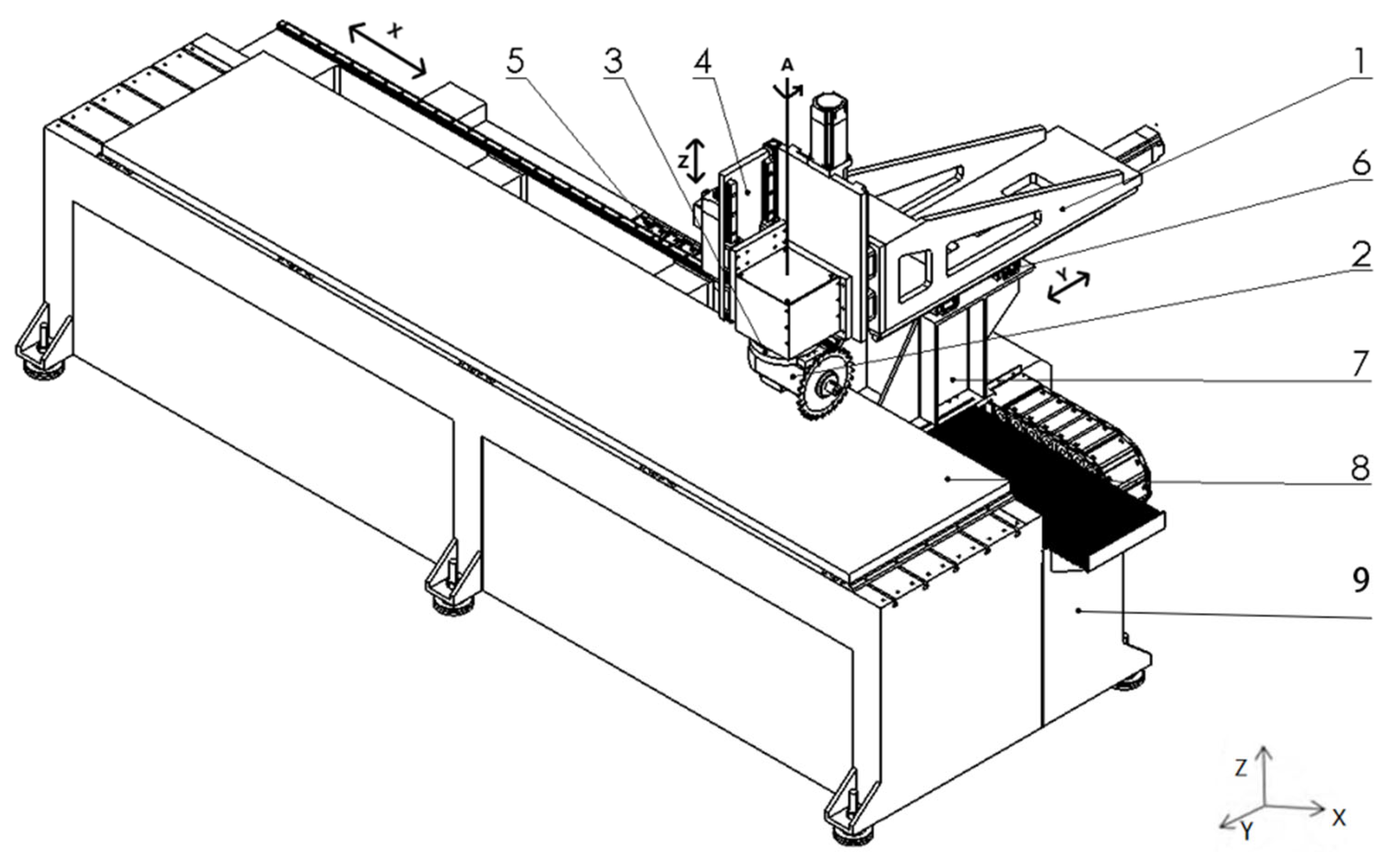
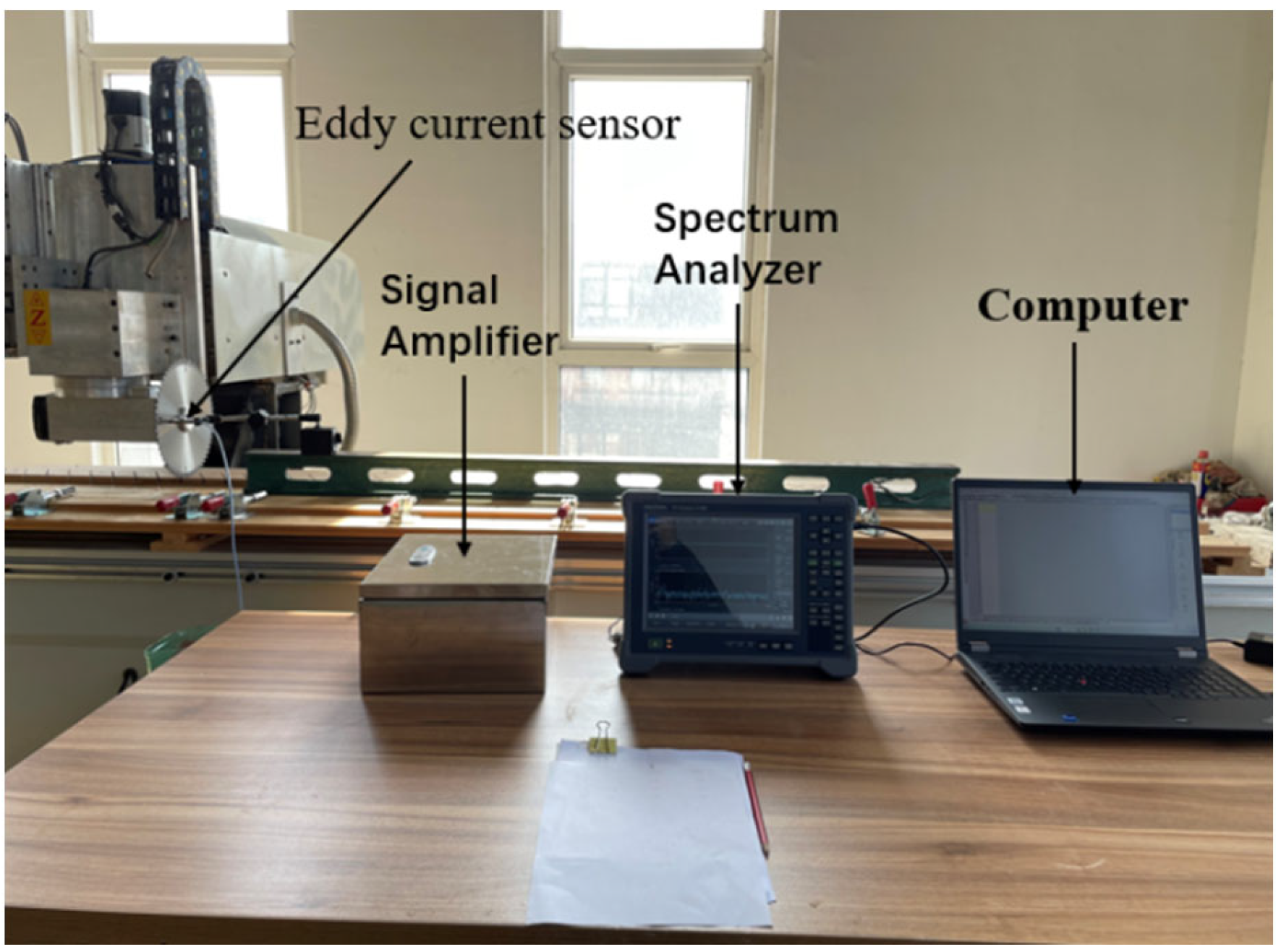
2.1. Experimental Equipment and Materials

Mobile cantilever-type four-coordinate CNC circular sawing machine, as shown in Figure 1. It mainly included cantilever beam 1, sawing head 2, rotary indexing device 3 (A-axis), vertical feed device 4 (Z-axis), longitudinal feed device 5 (X-axis), mobile cantilever transverse feed device 6 (Y-axis), column 7, bench 8, frame 9, etc. The circular saw blade was mounted on spindle motor shaft, and the spindle motor was fixed below rotary indexing device, the rotary indexing device set on the vertical feed device with guide rail, which was installed at the end of moving cantilever beam. The lower side of the moving cantilever beam was mounted above the bracket with guide rail, which was driven by the transverse feed device for transverse feed motion along with the bench. The lower side of the column mounted on the frame with guide rail was driven by the longitudinal feed device for longitudinal motion along with the bench.
During processing, the cutting angle of circular saw blade was adjusted by the rotary indexing device according to fixed angle. The saw blade was driven by the transverse and longitudinal feed devices in the feed motion to complete sawing process. The main technical parameters: The X-axis stroke of 3000 mm, the Y-axis stroke of 300 mm, the Z-axis stroke of 150 mm, and the rotation indexing range of 0~360°.
The device for collecting transverse vibration signal of circular saw blade, as shown in Figure 2, consists of eddy current sensor, signal amplifier, spectrum analyzer, and computer. The eddy current sensor manufactured by ANRUO Shanghai includes a probe, cable, and signal amplifier. The probe model is VB-Z9808, and the signal amplifier is DH2-D08 which provides the required power for the probe to amplify and filter the signal. The eddy current sensor had a resolution of ±1 µm, a nonlinearity of less than 1%, a standard sensitivity of 0.008 mA/μm, a measuring range of 0~2.0 mm, and a sampling frequency of 10 kHz, and a sensor displacement output curve is shown in Figure 3.
Spectrum analysis was performed by the CF-9200 analyzer from ONOSOKKI Japan, which has a sampling frequency of up to 100 kHz. The 4096 sampling points were set at the interval of every 4 Hz in the experiment.
The used natural wood material was Pterocarpus tinctorius Welw with a moisture content of 12%, dimensions of 200 mm × 100 mm × 20 mm, and a density of 1.2 × 10³ kg/m3. It belongs to high-density wood, resulting in bigger vibration during cutting, which was helpful to assess the effect of machine structure on transverse vibration compared to low density.

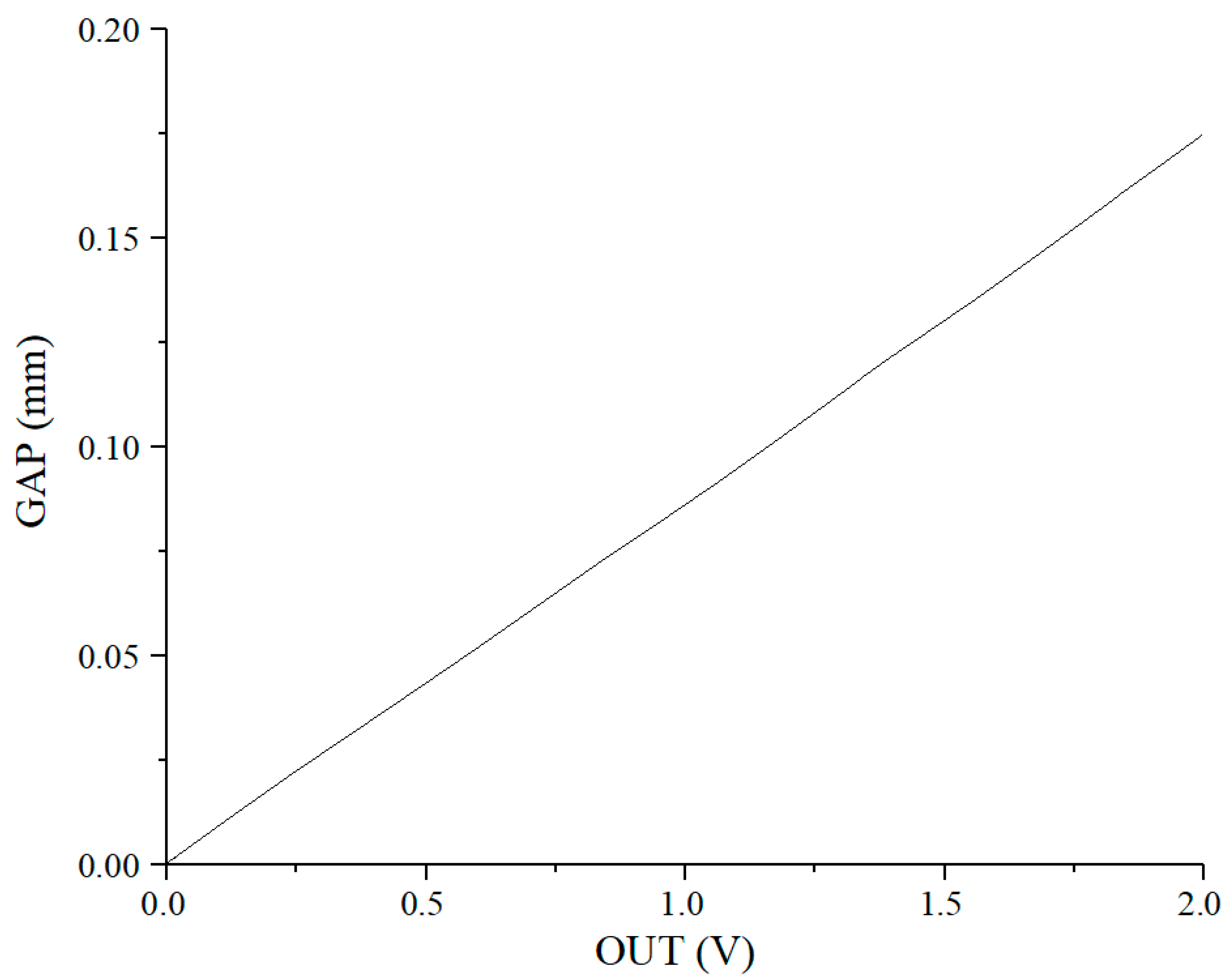
2.2. Experimental Procedures, Signal Acquisition, and Processing

The parameters for the carbide circular saw blade made from 65 Mn: a diameter of 254 mm, a body thickness of 1.8 mm, a tooth width of 2.4 mm, 60 teeth in total, and 4 silencing grooves were evenly distributed on the saw body. On both sides of the circular saw blade, the flanges with a diameter of 50 mm were used for clamping. To avoid the impact of silencing grooves on signal acquisition, the position located 95 mm away from the center of the circular saw blade was selected as the maximum radius point for detection. The experimental operation was divided into three steps A, B, and C as follows:
  • Change the overhang length of circular saw blade, keep the constant radius distance between the detection point and the center of the circular saw blade, and then detect the transverse vibration of no-load saw blade.
  • Change the radius distance of the detection point away from the center of the circular saw blade, keep the constant overhanging length, and then detect the transverse vibration of no-load saw blade.
  • Sawing: set the overhang length starting from 0 to 300 mm (Y-axis direction), keep the constant cutting speed, feed speed, and cutting depth, and then detect the transverse vibration of the circular saw when Y-axis was set as 0, 150 mm, and 300 mm, separately.
The experimental parameters were set as shown in Table 1, and all of the experiments were repeated three times.
The sampling frequency was set to 10 kHz in the experiment. Under no-load conditions, the signal was collected after the circular saw blade was rotated stably on the spindle of sawing machine, lasting for 10 s, while the collection lasted for 5 s during the loaded state. The five segments of the collected signal were randomly picked up for analyzing average value. The root mean square value ( V r m s ) was used for the power spectrum, and its calculation formula is:
V r m s = 1 T ( 0 T X 2 d t )
Here in, X: instant value; T: time.

3. Results and Discussion

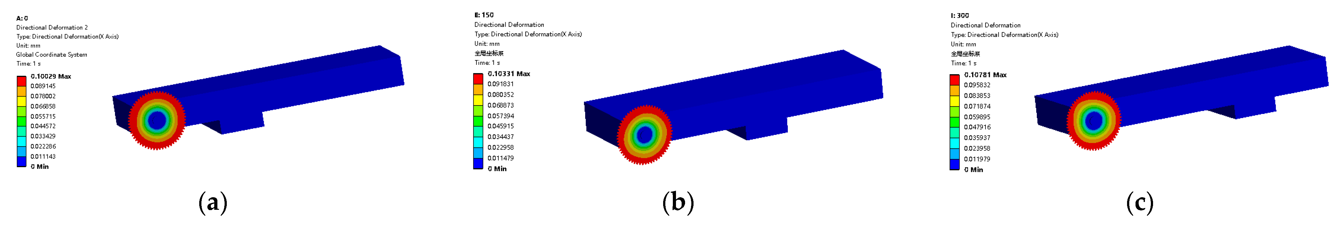
3.1. Simulation Results

The deformation resulting from the rotation of the circular saw blade was simulated using ANSYS simulation software, where the entire mobile cantilevered circular saw machine was simplified into one circular saw blade fixed at the front end of the cantilever and the other movable bracket fixed to the bottom. The material properties of the saw blade were 65 Mn: the density of 7800 kg/m3, Yong’s modulus of 2 × 10¹¹ N/m2, and Poisson’s ratio of 0.3. The cantilever and the bracket were made from A48 Gray Cast Iron with a density of 7280 kg/m3, Yong’s modulus of 1.8 × 10¹¹ N/m2, and Poisson’s ratio of 0.156. The model geometrically meshed with tetrahedral elements, and the mesh size was set as 20 mm for the cantilever and the bracket and 5 mm for the circular saw blade. The circular saw blade was fixed to the end of the cantilever by the flange with a diameter of 50 mm. There were fixed constraints between the flange and the bottom of the bracket. The entire machine was subject to gravity factor in reality. When the rotational speed of the circular saw blade was set to 4000 r/min, the position of the bottom bracket of the cantilever was varied to simulate the changes in cantilever length. The bracket position was set at the positions of 0, 150, and 300 mm on the Y-axis, respectively.
Figure 4 shows the transverse deformation of the circular saw blade in rotation under different cantilever lengths, where the transverse deformation was gradually increased from the center to the outer edge along with the saw blade radius and the minimum deformation occurred at the clamping place. The transverse deformation of the saw blade was also augmented with the increase in the overhang length. The minimum deformation of 0.100 mm appeared at the overhang length of 0, then 0.103 mm at 150mm, and the maximum deformation of 0.108 mm happened at 300 mm.

3.2. Transverse Vibration of Saw Blade with Different Overhang Lengths at No-Load

Figure 5 shows the time domain diagram of the transverse vibration of the circular saw blade at different overhang lengths under no-load conditions, which displayed the transverse vibration signals were periodic, and the period length of each movement was the time for one rotation of the circular saw blade (0.015 s). The maximum transverse vibration values of the circular saw blade were 0.136, 0.139, and 0.143 mm when the cantilever was at the Y-axis of 0, 150, and 300 mm, respectively. The transverse amplitude of the circular saw blade was increased within the small range as the overhang length was extended. Theoretically, the longer the cantilever, the greater the elastic deformation of the shaft end, which aggravated the transverse displacement of the shaft end together with the effect of the flange during the rotation. Indeed, there was little variation in the waveform of the transverse vibration time domain diagram with the increase in the cantilever length, but the amplitude was increased slightly.
Figure 6 shows the probability density distribution of transverse vibration under different overhang lengths at no-load. The amplitude was almost symmetrically distributed about 0, with a bimodal pattern, which conformed to the distribution characteristics of the overlaying of the sine wave and random noise. As the overhanging length was extended, the distributions of transverse vibration amplitude were from −0.068~0.069 mm, −0.070~0.071 mm, and −0.072~0.073 mm. while the maximum transverse amplitude was increased from 0.138~0.146 mm.
Figure 7 shows the transverse vibration power spectrum at different overhang lengths without loading. The circular saw blade had a rotation frequency of 66.7 Hz at all three positions was also 66.7 Hz, which was corresponding to rotational speed. The spectrograms of the different overhanging positions in the idle state are roughly the same. The fundamental and secondary frequencies of the three plots were basically equal, with a slight difference between 200 Hz and 500 Hz. which might be attributed to the trivial change in the vibration mode of the mechanical structure of the guide rail extension [36]. The vibration was hardly observed at the saw tooth frequency of 4000 Hz, indicating the sawtooth had little effect on transverse vibration. Similarly, the variation of the cantilever length almost did not generate transverse vibration.

3.3. The Transverse Vibration of Different Detecting Points on Saw Blade at No-Load

Figure 8 shows the time domain diagrams of the transverse vibration of circular saw blades at different detecting points without loading. The time domain plots of the three detection point positions were periodically varied. The transverse vibration was the smallest in Figure 8a, the middle in Figure 8b, and the largest in Figure 8c. More transverse vibration was observed between 0~0.01 mm in Figure 8a, which might be due to the subtle change in the saw body surface. The maximum transverse displacements were 0.154, 0.139, and 0.061 mm corresponding to the detecting positions of 95, 70, and 45 mm, respectively. When the rotational speed and the cantilever length were kept constant, the transverse vibration of the saw blade was increased with the augment of the detection distance. The circular saw blade was simplified as a circular plate with solid support in the middle and a free outer ring, which was prone to axial deformation when it was imposed with axial force [37]. The farther the detection point away from the center of the circular saw blade, the more significant the axial deformation, and the increase rate was reduced with the elevation of the radius distance. This was consistent with the trend of simulation results without load.
Figure 9 shows the probability distribution of transverse vibration of circular saw blades at different detecting points. When the detecting point was located at 45, 70, and 95 mm, respectively, the amplitude range of transverse vibration of the circular saw blade was gradually increased from −0.034~0.029 mm, −0.070~0.071 mm, and −0.076~0.080 mm, indicating the farther away from the center of the saw blade, the greater the transverse vibration of the saw blade, which was consistent with the analytical result in the time domain diagram.
The transverse vibration power spectrum of the circular saw blade at different detecting points is shown in Figure 10, where the amplitudes reached the maximum when the fundamental frequency was 66.7 Hz at all three positions. The amplitudes of the fundamental, double fundamental, and triple fundamental frequencies were gradually decreased, which complied with the law of power spectrum of rotating circular saw blades. The amplitudes of fundamental, double, and triple frequencies in Figure 10c were larger than those in Figure 10a,b, which might be caused by: 1, The center of the circular saw blade was tightly clamped by the flange, increasing the dynamic stability of the circular saw blade. 2, The transverse vibration was generally combined with radial and torsional vibrations during the rotation of the circular saw blade [38], which was also affected by radial and torsional vibrations when the detecting distance was increased.

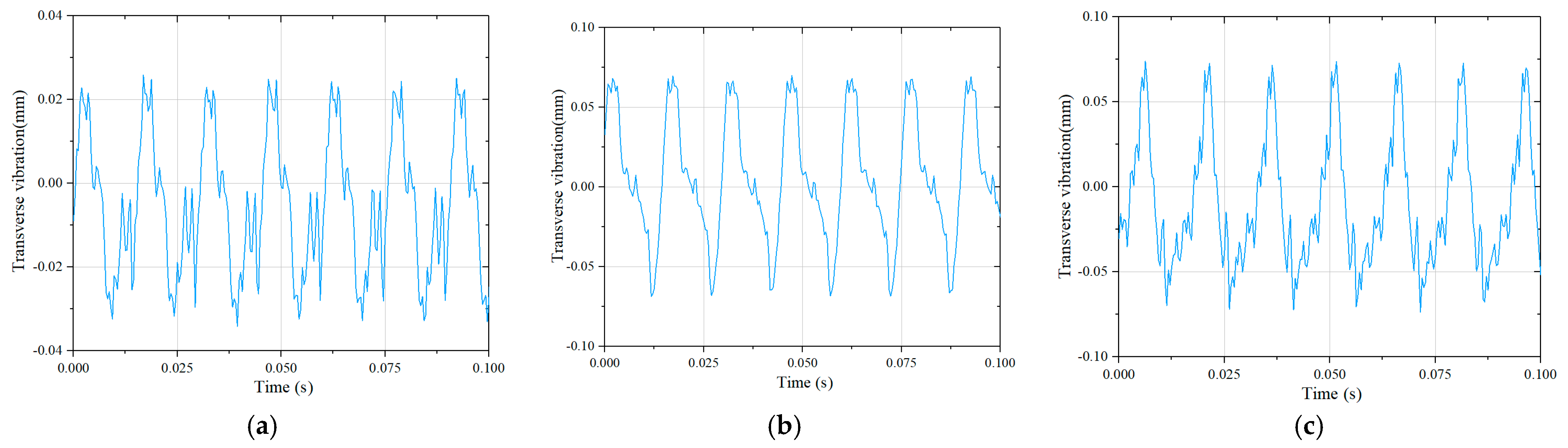
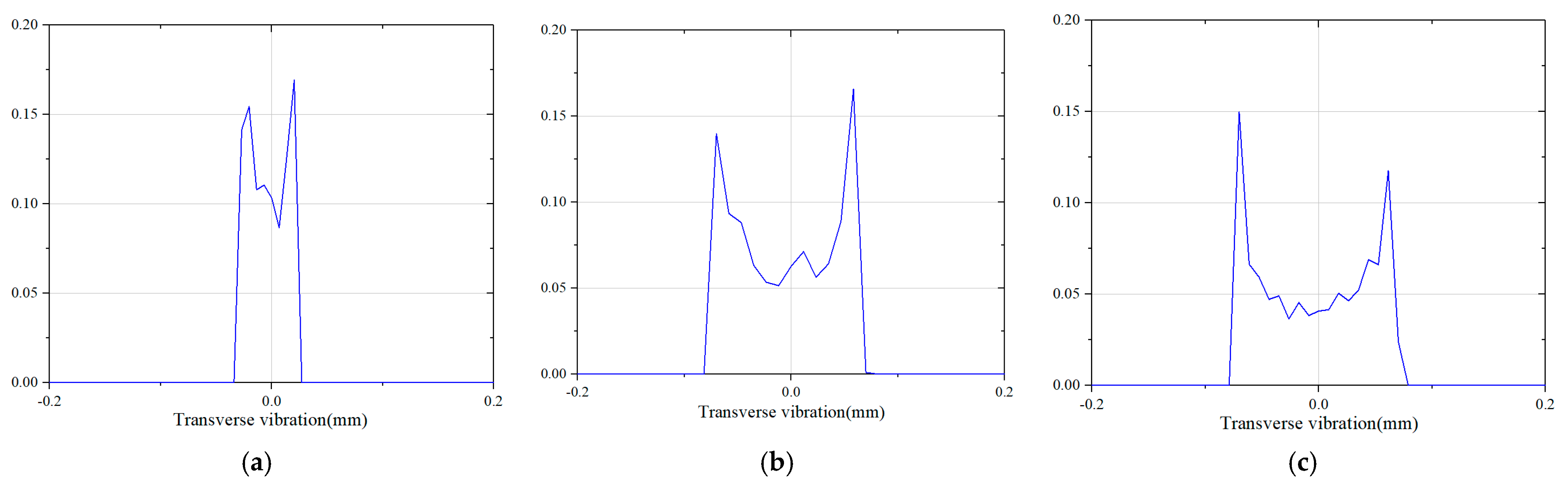
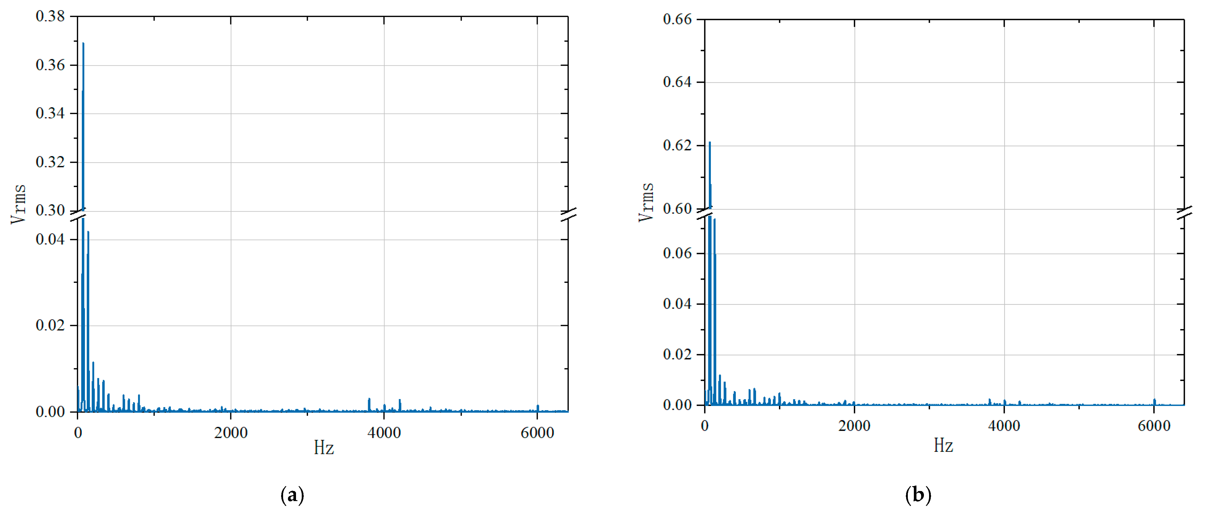
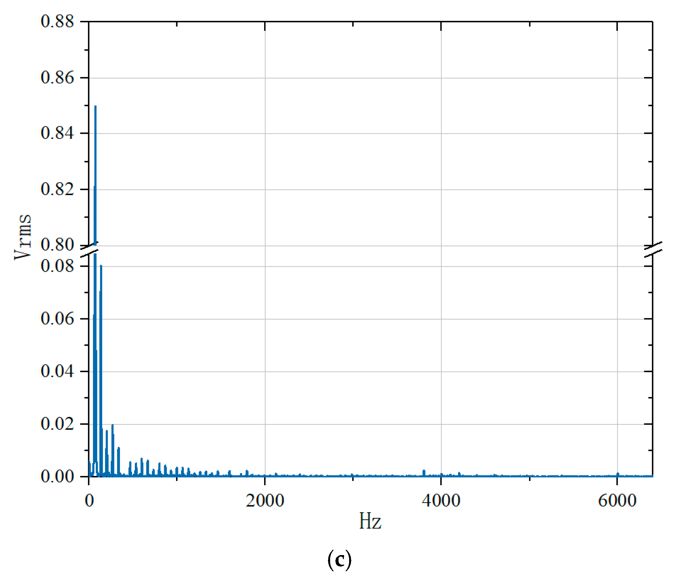
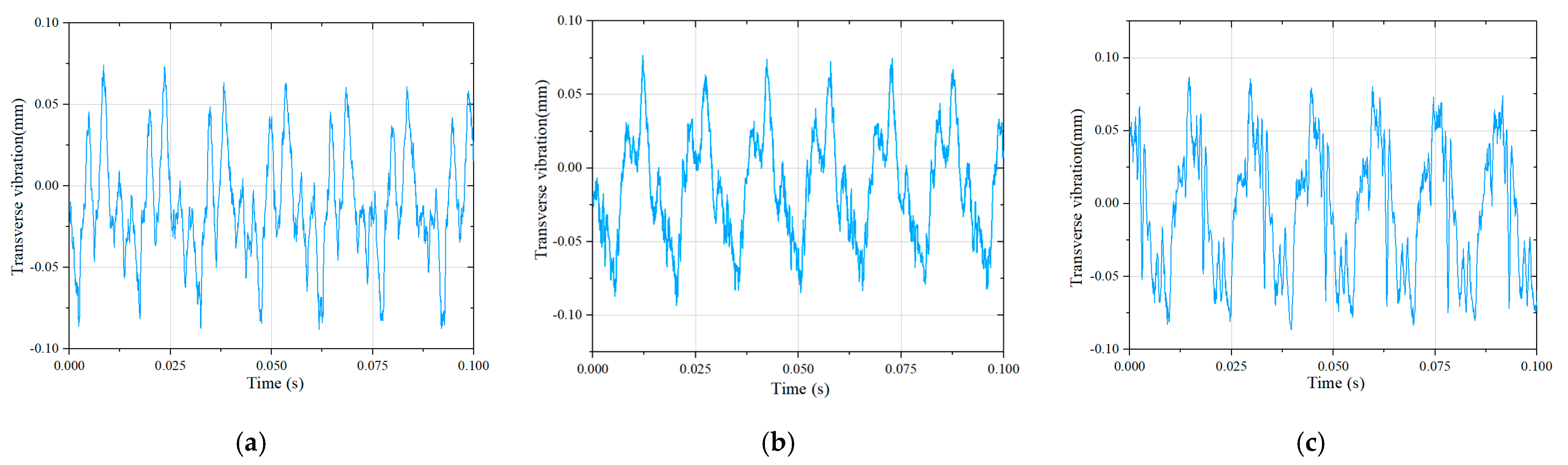
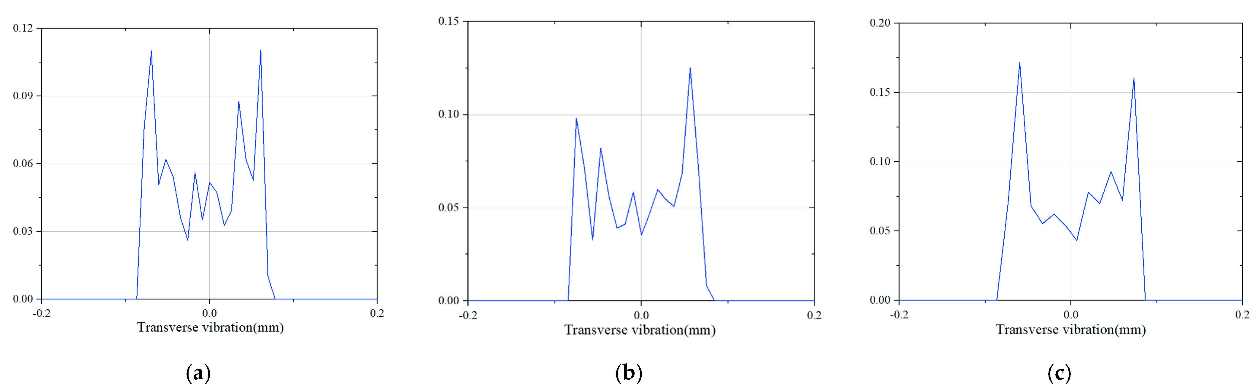
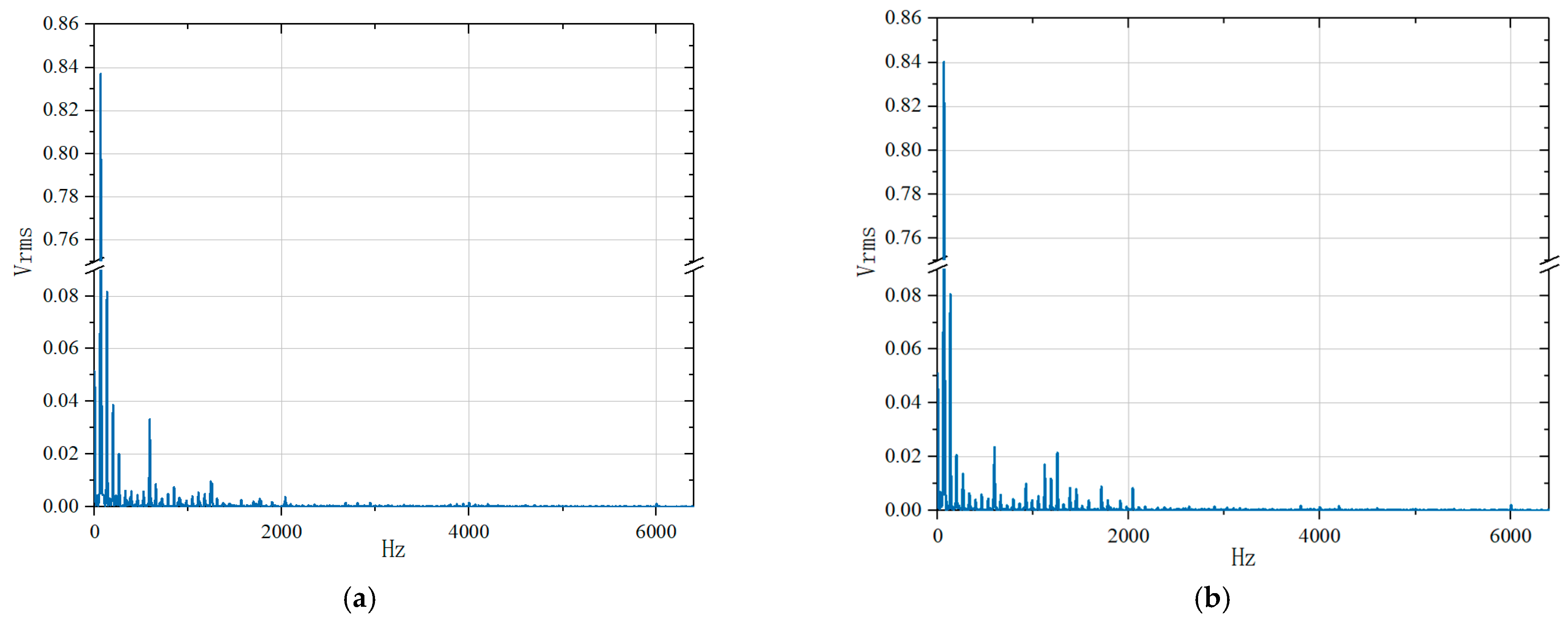
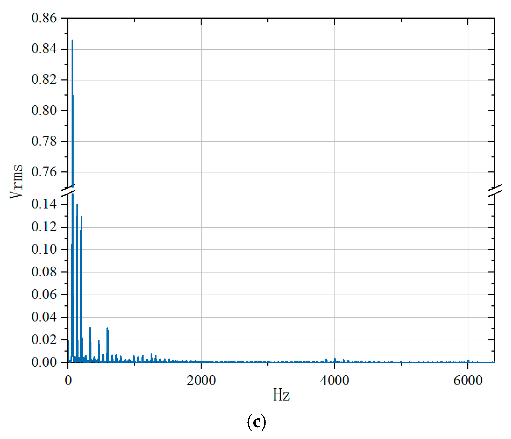
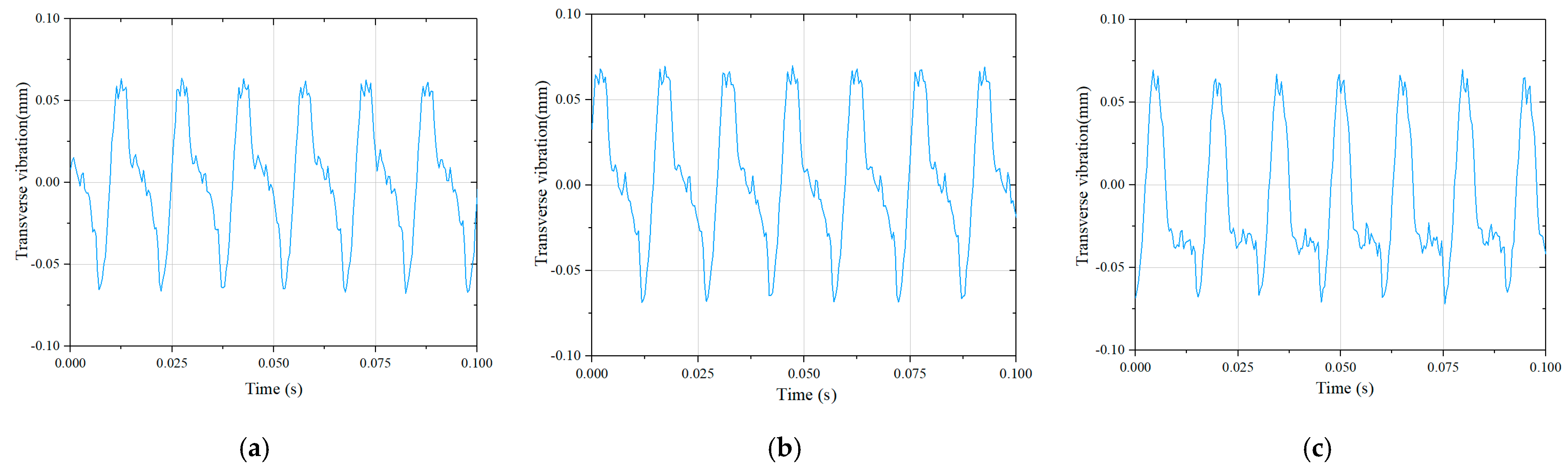
3.4. The Transverse Vibration of Circular Saw Blade When Sawing

The Y-axis of the machine was fed uniformly at the speed of 3 m/min, and the transverse vibration of the saw blade was detected by the eddy current sensor at the Y-axis of 0, 150, and 300 mm, respectively. Figure 11 shows the time domain diagram of circular saw blade transverse vibration at different overhang lengths during wood sawing. At all three positions, the time domain signals varied periodically. Compared with the signal under no-load with the same parameters, we found that: 1, The circular saw blade transverse vibration was increased up to 0.165, 0.169, and 0.173 mm, respectively. This was probably the consequence of the resisting force of wood specimens while sawing, which intensified the radial and torsional vibration of the saw blade in rotation, and the combination of various vibrations enhanced the transverse vibration of the saw blade more intensely. 2, More trivial vibrations were displayed in the time domain waveform, which might be due to more complex micro-fine vibrations of the saw blade resulting from cutting resistance. The longer the length of the cantilever, the more severe the transverse vibration generated by the circular saw blade. During processing, the maximum transverse vibration was 0.173 mm at the cantilever length of 300 mm.
Figure 12 shows the probability density distribution of transverse vibration of circular saw blades at different overhang lengths during sawing. As the overhang length was set at 0, 150, and 300mm, respectively, the range of the transverse vibration of the saw blade varied from −0.078mm~0.087 mm, −0.085~0.085 mm, −0.087~0.087 mm, where the maximum value of the transverse vibration was enhanced. This might be attributed to the transverse vibration of the circular saw blade, affected by the change in the CNC machine tool structure at the longer overhang length.
Figure 13 shows the power spectrum of transverse vibration of circular saw blades at different overhanging lengths during sawing. The fundamental frequency dominated, but the amplitudes for the double, triple, and quadruple fundamental frequencies were not decreased progressively, which might result from the following reasons: 1, The interference of sawdust and wood chips generated in cutting. 2, The vibration interference of the CNC machine during cutting. 3, Air vibration fluctuated around the saw blade when the circular saw blade was rotated at various cantilever lengths during cutting [39], which disturbed the amplitudes of the double, triple, and quadruple harmonic frequencies.

3.5. The Establishment of Mathematical Models

Figure 14 shows the liner fit curves for the maximum transverse vibration values of the circular saw blade in the simulated, no-load, and actual cutting states at different overhang lengths. The transverse vibration of the circular saw blade was gradually increased with the increase in overhang length regardless of any state, and the transverse vibration for the simulation was the smallest and for the actual cutting was the largest under the same condition. The fitting functions were expressed as:
f ( s 1 ) = 2.45 × 10 5 L + 0.100
f ( s 2 ) = 2.55 × 10 5 L + 0.135
f ( s 3 ) = 2.67 × 10 5 L + 0.165
Herein, L was the overhang length (mm); f s was the maximum transverse vibration value of the saw blade (mm), s1: simulated; s2: no-load; s3: actual cutting.

4. Conclusions

In the study, the effect of overhang length on the transverse vibration of the circular saw blade at different positions was explored using the cantilever-type CNC circular sawing machine in simulation and the actual cutting process with and without loading. The results were summarized below:
(1)
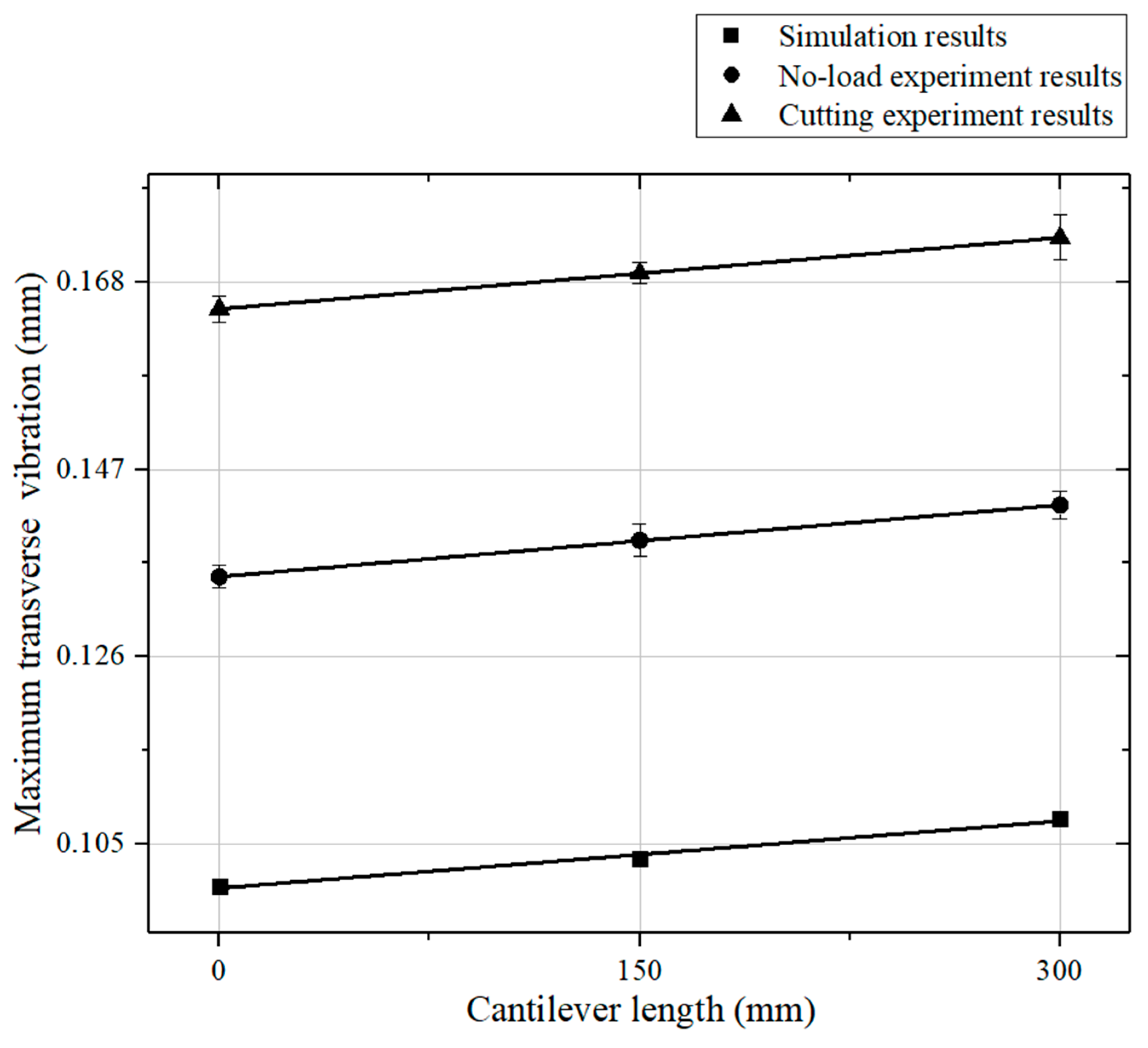
The maximum amplitude of the transverse vibration of the circular saw blade was augmented with the increase in cantilever length in the simulation, no-load, and actual cutting.
(2)
The transverse vibration of the circular saw blade was gradually increased from the center to the outer edge along with the radius direction when the overhang length was kept constant, and the transverse vibration of the circular saw blade was the smallest at the place clamped with the flange. The maximum transverse vibration value of the circular saw blade is increased from 0.061 mm to 0.154 mm when the detecting point changes from 45 mm to 95 mm.
(3)
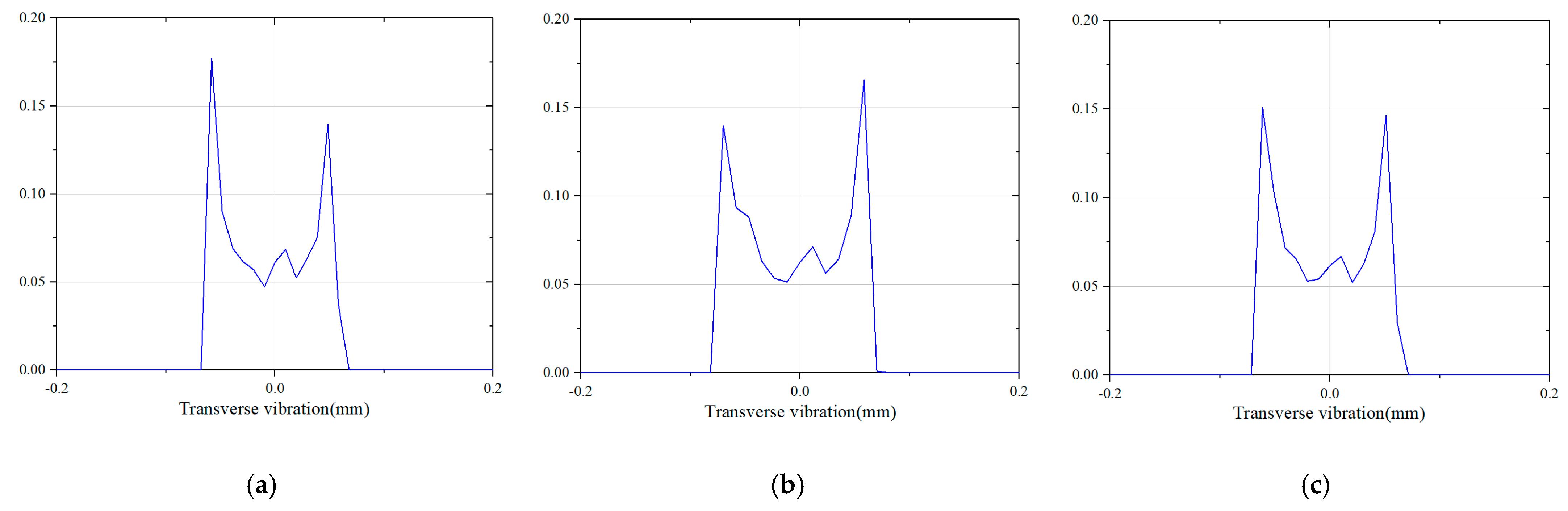
The transverse amplitudes of the circular saw blade were 0.165, 0.169, and 0.173 mm, respectively, corresponding to the overhang length of 0, 150, and 300mm during wood sawing, indicating the transverse vibration was hardly changed within 300 mm of overhang length.
The finding provides a theoretical foundation for further understanding and developing CNC woodworking circular saw machines with long overhang lengths in the future.

Author Contributions

Conceptualization, X.Y. and B.W.; methodology, X.Y., Y.C. and N.Z.; software, Y.C. and H.Q.; validation, Y.C.; formal analysis, X.Y., Y.C., H.Q. and N.Z.; resources, B.W.; data curation, H.Q. and T.D.; writing—original draft preparation, X.Y.; writing—review and editing, T.D., N.Z. and B.W.; visualization, X.Y.; All authors have read and agreed to the published version of the manuscript.

Funding

This research was funded by the National Key R&D Program of China (Grant Number: 2016YFD0600703) and A Project Funded by the National First-class Disciplines (PNFD).

Data Availability Statement

Not applicable.

Conflicts of Interest

The authors declare no conflict of interest.

References

  1. Yao, T.; Duan, G.L.; Cai, J. Review of vibration characteristics and noise reduction technique of circular saws. J. Vib. Shock. 2008, 27, 162–166. [Google Scholar]
  2. Nasir, V.; Cool, J. A review on wood machining: Characterization, optimization, and monitoring of the sawing process. Wood Mater. Sci. Eng. 2018, 15, 1–16. [Google Scholar] [CrossRef]
  3. Kopecký, Z.; Svoreň, J.; Peršin, M.; Rousek, M.; Klepárník, J. Circular saw blades vibrations effect on parameters of a cutting process. In Proceedings of the 2nd International Scientific Conference on Woodworking Technique, Zalesina, Croatia, 11–15 September 2007; pp. 267–276. [Google Scholar]
  4. Yuan, M.H.; Tong, S.G.; Cai, Q.; Tang, N. Dynamics study and damping optimization of circular saw based on numerical simulation and experimental analysis. In Proceedings of the 3rd International Conference on Engineering Design and Optimization (ICEDO 2012), Shaoxing, China, 25–27 May 2012; pp. 364–369. [Google Scholar]
  5. Chen, Y.; Wang, X.G.; Sun, C.; Devine, F.; De Silva, C.W. Active vibration control with state feedback in woodcutting. J. Vib. Control 2003, 9, 645–664. [Google Scholar] [CrossRef]
  6. Stevenson, D.; Gray, W.; Hoong, K.; Speller, M. Quietening circular saws by reducing blade vibration. Noise Control Eng. J. 1989, 33, 33–37. [Google Scholar] [CrossRef]
  7. Wang, X.; Xi, F.J.; Li, D.; Qin, Z. Estimation and control of vibrations of circular saws. In Proceedings of the 1999 IEEE International Conference on Control Applications (Cat No 99CH36328), Kohala Coast, HI, USA, 22–27 August 1999; pp. 514–520. [Google Scholar]
  8. Li, L.; Xi, B.T.; Yang, Y.F. The developments in the vibration, dynamic stability and control research of circular saw-the analysis on vibration and dynamic stability of cicular saw. China J. Woodwork. Mach. 2002, 2, 5–10. [Google Scholar]
  9. Hlaskova, L.; Kopecky, Z.; Vesely, P.; Svoboda, E.; Kowalski, M. Resonance stages of circular saw-blades with irregular tooth pitch and kerf quality. In Proceedings of the 8th International Science Conference on Chip and Chipless Woodworking Processes, Zvolen, Slovakia, 6–8 September 2012; pp. 125–130. [Google Scholar]
  10. Guo, X.L.; Cao, P.X.; Wang, H.L. Mechanism of the noise generation of a circular saw blade and technique for noise reduction. China J. For. Grassl. Mach. 2006, 2, 48–52. [Google Scholar]
  11. Nasir, V.; Mohammadpanah, A.; Cool, J. The effect of rotation speed on the power consumption and cutting accuracy of guided circular saw: Experimental measurement and analysis of saw critical and flutter speeds. Wood Mater. Sci. Eng. 2020, 15, 140–146. [Google Scholar] [CrossRef]
  12. Svoren, J.; Nascak, L.; Barcik, S.; Koleda, P.; Stehlik, S. Influence of Circular Saw Blade Design on Reducing Energy Consumption of a Circular Saw in the Cutting Process. Appl. Sci. 2022, 12, 1276. [Google Scholar] [CrossRef]
  13. Orlowski, K.; Sandak, J.; Tanaka, C. The critical rotational speed of circular saw: Simple measurement method and its practical implementations. J. Wood Sci. 2007, 53, 388–393. [Google Scholar] [CrossRef]
  14. Ukvalbergiene, K.; Vobolis, J. Experimental studies of wood circular saw forms. Wood Res. 2005, 50, 47–58. [Google Scholar]
  15. Xinpei, X.; Chengyong, W.; Jiayan, C.; Yasen, W. Effect of roll tensioning and clamping ratio on natural frequency of circular saw blade for wood cutting process. In Proceedings of the 13th International Conference on Tools (ICT 2012), Miskolc, Hungary, 27–28 March 2012; pp. 89–94. [Google Scholar]
  16. Schajer, G. Simple formulas for natural frequencies and critical speeds of circular saws. For. Prod. J. 1986, 36, 36–43. [Google Scholar]
  17. Dugdale, D.S. Stiffness of a spinning disc clamped at its center. J. Mech. Phys. Solids 1966, 14, 349–356. [Google Scholar] [CrossRef]
  18. Marui, E.; Ema, S.; Miyachi, R. An experimental investigation of circular saw vibration via a thin plate model. Int. J. Mach. Tools Manuf. 1994, 34, 893–905. [Google Scholar] [CrossRef]
  19. Cheng, W.; Yokochi, H.; Kimura, S.; Mano, K. Dynamic characteristics of circular saws in the region of the critical rotation speed. Mokuzai Gakkaishi 2000, 46, 311–319. [Google Scholar]
  20. Raman, A.; Mote, C.D. Remarks on the non-linear vibration of an axisymmetric circular disk near critical speed. Int. J. Non-Linear Mech. 2002, 37, 35–41. [Google Scholar] [CrossRef]
  21. Baddour, N.; Zu, J.W. A revisit of spinning disk models. Part I: Derivation of equations of motion. Appl. Math. Model. 2001, 25, 541–559. [Google Scholar] [CrossRef]
  22. Baddour, N.; Zu, J.W. A revisit of spinning disk models. Part II: Linear transverse vibration. Appl. Math. Model. 2001, 25, 561–578. [Google Scholar] [CrossRef]
  23. Pahlitzsch, G.; Rowinski, B. Über das Schwingungsverhalten von Kreissägeblättern—Zweite Mitteilung: Ermittlung und Auswirkungen der kritischen Drehzahlen und Eigenfrequenzen der Sägeblätter. Eur. J. Wood Wood Prod. 1966, 24, 341–346. [Google Scholar] [CrossRef]
  24. Tobias, S.; Arnold, R. The influence of dynamical imperfection on the vibration of rotating disks. Proc. Inst. Mech. Eng. 1957, 171, 669–690. [Google Scholar] [CrossRef]
  25. Leu, M.; Mote, C. Origin of idling noise in circular saws and its suppression. Wood Sci. Technol. 1984, 18, 33–49. [Google Scholar] [CrossRef]
  26. Nishio, S.; Marui, E. Effects of slots on the lateral vibration of a circular saw blade. Int. J. Mach. Tools Manuf. 1996, 36, 771–787. [Google Scholar] [CrossRef]
  27. Yu, R.-C.; Mote, C.D. Vibration of circular saws containing slots. Holz Roh Werkst. 1987, 45, 155–160. [Google Scholar] [CrossRef]
  28. Wang, Y.K.; Mote, C.D., Jr. Analysis of an arbitrary shaped guide bearing subject to normal oscillation and translation of a plate. Wear 1996, 198, 115–121. [Google Scholar] [CrossRef]
  29. Tian, J.F.; Hutton, S.G. Cutting-induced vibration in circular saws. J. Sound Vib. 2001, 242, 907–922. [Google Scholar] [CrossRef]
  30. Li, Z.; Zhu, G.; Qi, Y.; Chen, S.; Zhang, Z. Research Survey of Dynamic Performance of Woodworking Circular Disk Saw. China J. For. Mach. Woodwork. Equip. 2000, 1, 4–9. [Google Scholar]
  31. Liu, X. Dynamic Study of Rotor System in Woodworking Circular Saw Machine. Ph.D. Thesis, Beijing Forestry University, Beijing, China, 2008. [Google Scholar]
  32. Vesel, P.; Kopeck, Z.; Hejmal, Z.; Pokorn, P. Diagnostics of Circular Sawblade Vibration by Displacement Sensors. Drv. Ind. 2012, 63, 81–86. [Google Scholar] [CrossRef]
  33. Droba, A.; Javorek, Ľ.; Svoreň, J.; Paulíny, D. New design of circular saw blade body and its influence on critical rotational speed. Drewno 2015, 58, 147–158. [Google Scholar]
  34. Kaczmarek, A.; Orlowski, K.; Javorek, L. A brief review and comparison of selected experimental methods for measuring natural frequencies of circular saw blades. Drewno 2016, 59, 197. [Google Scholar]
  35. Munz, U. Vibration behavior and residual manufacturing stresses of circular sawblades. In Proceedings of the 17th International Wood Machining Seminar, Rosenheim, Germany, 26–28 September 2005. [Google Scholar]
  36. Ma, G.; Xu, M.; An, Z.; Wu, C.; Miao, W. Active vibration control of an axially moving cantilever structure using MFC. Int. J. Appl. Electromagn. Mech. 2016, 52, 967–974. [Google Scholar] [CrossRef]
  37. Mote, C.D., Jr. Stability of circular plates subjected to moving loads. J. Frankl. Inst. 1970, 290, 329–344. [Google Scholar] [CrossRef]
  38. Yao, T. Mechanism Study on Vibration and Noise Reduction of Circular Saw with Slots. Ph.D. Thesis, Hebei University of Technology, Hebei, China, 2009. [Google Scholar]
  39. Cheng, W.; Yokochi, H.; Kimura, S. Aerodynamic sound and self-excited vibration of circular saw with step thickness I: Comparison of dynamic characteristics between the common circular saw and the circular saw with step thickness. J. Wood Sci. 1998, 44, 177–185. [Google Scholar] [CrossRef]
Figure 1. Four-coordinate mobile cantilever-type CNC circular sawing machine. (1. Cantilever beam, 2. sawing head, 3. rotary indexing device (A-axis), 4. vertical feeding device (Z-axis), 5. longitudinal feeding device (X-axis), 6. mobile cantilever transverse feeding device (Y-axis), 7. column, 8. table, 9. frame.).
Machines 11 00549 g001
Figure 2. Physical diagram of the detection system.
Machines 11 00549 g002
Figure 3. The sensor displacement output curve.
Machines 11 00549 g003
Figure 4. The displacement in simulation results ((a) The cantilever at Y-axis of 0 mm (b) The cantilever at the Y-axis of 150 mm (c) The cantilever at the Y-axis of 300 mm).
Machines 11 00549 g004
Figure 5. Time domain diagram of transverse vibration at different overhang lengths without loading ((a) The cantilever at Y-axis of 0 mm (b) The cantilever at Y-axis of 150 mm (c) The cantilever at Y-axis of 300 mm).
Machines 11 00549 g005
Figure 6. Probability density distribution of transverse vibration at different overhang lengths without loading ((a) The cantilever at Y-axis of 0 mm (b) The cantilever at Y-axis of 150 mm (c) The cantilever at Y-axis of 300 mm).
Machines 11 00549 g006
Figure 7. Transverse vibration power spectrum at different overhang lengths without loading ((a) The cantilever at Y-axis of 0 mm (b) The cantilever at Y-axis of 150 mm (c) The cantilever at Y-axis of 300 mm).
Machines 11 00549 g007aMachines 11 00549 g007b
Figure 8. Time domain diagram of circular saw blade transverse vibration at different detection points. ((a) The distance between the detection point and the center of the circular saw blade: 45 mm (b) The distance between the detection point and the center of the circular saw blade: 70 mm (c) The distance between the detection point and the center of the circular saw blade: 95 mm).
Machines 11 00549 g008
Figure 9. Probability density distribution of circular saw blade transverse vibration at different detection points. ((a) The distance between the detection point and the center of the circular saw blade: 45 mm (b) The distance between the detection point and the center of the circular saw blade: 70 mm (c) The distance between the detection point and the center of the circular saw blade: 95 mm).
Machines 11 00549 g009
Figure 10. Power spectrum of circular saw blade transverse vibration at different detection points. ((a) The distance between the detection point and the center of the circular saw blade: 45 mm (b) The distance between the detection point and the center of the circular saw blade: 70 mm (c) The distance between the detection point and the center of the circular saw blade: 90 mm).
Machines 11 00549 g010aMachines 11 00549 g010b
Figure 11. Time domain diagram of transverse vibration of circular saw blades at different overhang lengths during sawing ((a) The cantilever at Y-axis of 0 mm (b) The cantilever at Y-axis of 150 mm (c) The cantilever at Y-axis of 300 mm).
Machines 11 00549 g011
Figure 12. Probability density distribution of transverse vibration of circular saw blade at different overhang lengths during sawing ((a) The cantilever at Y-axis 0 mm (b) The cantilever at Y-axis 150 mm (c) The cantilever at Y-axis 300 mm).
Machines 11 00549 g012
Figure 13. The power spectrum of transverse vibration of circular saw blade at different overhang lengths during sawing ((a) The cantilever at Y-axis 0 mm (b) The cantilever at Y-axis 150 mm (c) The cantilever at Y-axis 300 mm).
Machines 11 00549 g013aMachines 11 00549 g013b
Figure 14. Comparison of experimental results with predictive models.
Machines 11 00549 g014
Table 1. Experiment parameter settings.
No-Load ExperimentSawing Experiment
Experiment ProcedureABC
Overhanging length of circular saw blade (mm)01500
150150
300300
Circular saw blade diameter (mm)254254254
The number of teeth606060
Flange diameter (mm)505050
Clamping ratio0.1970.1970.197
Circular saw blade rotation speed (rad/min)400040004000
Saw blade frequency (Hz)66.766.766.7
Cutting speed (m/s)535353
Distance from the center of the circular saw blade to the detecting point (mm)704595
70
95
The distance of the probe from the side of the circular saw blade (mm)111
Feed speed (m/min)003
Cutting depth (mm) 10
Sawing direction Parallel to Y-axis and with the texture direction of the wood
Disclaimer/Publisher’s Note: The statements, opinions and data contained in all publications are solely those of the individual author(s) and contributor(s) and not of MDPI and/or the editor(s). MDPI and/or the editor(s) disclaim responsibility for any injury to people or property resulting from any ideas, methods, instructions or products referred to in the content.

