Abstract
In the production process of oil and gas wells, the migration of solid particles, such as mud and sand, often leads to screen pipe clogging, resulting in production reduction or even shutdown. Controlled plasma pulse plugging removal technology is a new physical method for unplugging. Plasma, generated by the electrical explosion of the wire, then triggers a shock wave, which can remove the plugging. In this paper, the performance of controllable plasma pulse plugging removal technology is evaluated by simulating the plugging state of the downhole screen through laboratory experiments. The test results of screen plate unplugging effect evaluation fully show that the plasma pulse decongestion technology can carry out effective decongestion, can effectively reduce the pressure behind the clogging zone and increase the flow rate of the clogging zone, and is suitable for different screen plate blockage states such as mild, moderate and severe. Thus, this technology has a good application prospect.
1. Introduction
In the production process of oil and gas wells, sand production is one of the most important problems affecting oil well output. Solid particles, such as fine sand, silt, mechanical impurities, and mud carried by formation fluids, impact the sand retaining medium. Some of the solids cannot pass through the sand retaining layer smoothly and will adhere to the gap between the sand retaining layer, which leads to the reduction of permeability of the sand retaining layer, and then it forms a blockage, resulting in the state of low liquid output and low productivity of the oil well, and the continuous extension of the production cycle.
Existing plugging removal technologies have different degrees of advantages and disadvantages in specific uses. These plugging removal methods have shortcomings, such as causing damage to the formation, aggravating the erosion and aging of surface pipelines and equipment, and increasing the amount of sand produced in the later stage, leading to a worse plugging state. Controlled plasma pulse plugging removal technology is a kind of low-frequency electric pulse physical method, and the plugging removal principle is shown in Figure 1.
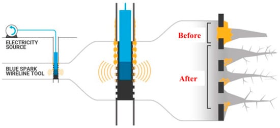
Figure 1.
Schematic diagram of controlled plasma pulse plugging removal technology.
As a physical method of unplugging and increasing permeability, plasma shock wave technology has the following functions in the production of oil and gas wells: (1) High-energy plasma shock waves can destroy the adhesion or inlaying state of mud and sand particles in the sand retaining medium, making these particles move along the diffusion direction of the shock wave, unblocking the fluid channel of the sand retaining medium, which can greatly improve the migration conditions of the extraction fluid medium, and achieve the purpose of unplugging and increasing the permeability of the wellbore in producing formation; (2) the technology will generate a certain amount of heat during the plasma discharge process, which can increase the temperature of the interval, have an auxiliary heating effect on the fluid medium, and can melt the organic matter, such as wax, gum and asphaltene attached to the wellbore and sand retaining medium, improving the flow performance of the fluid.
The early high-voltage pulse shock wave technology [1] studied the electrical breakdown of the water medium, that is, the liquid electric effect, which was first proposed by Soviet scientist Yutkin in 1955. Through years of research and experiments, he found a reasonable way to connect the circuit in the experiment and named this phenomenon the liquid electric effect. In 1956, Zingerman gave an empirical expression, , for the peak P of shock wave generated by needle discharge in the liquid electric effect. In this expression, β is a constant, and in water, β is 0.75; E0 is the energy deposited per unit length of the discharge channel; ρ is the density of the dielectric; τ is the wavefront time; Tp is the total pulse duration. From the above expression, it can be seen that reducing the wavefront time and the total duration of the pulse can generate more deposited energy per unit length and thus produce a larger shock wave.
In 1960, Martin [2] carried out systematic experiments and theoretical research. By inserting tungsten wires with a diameter of 1 mm between the electrodes, he found that the discharge could be more stable, energy leakage could be reduced, and shock wave intensity could be increased. In 1975, Tucker [3] proposed a calculation model for the electrical breakdown of arc wire and obtained the corresponding data between the electrical resistivity of various metals and the specific action through calculation and experiment. In 1988, Lee et al. [4] of White Oak Laboratory conducted a study on the disruptive discharge of aluminum and aluminum-lithium alloy electric exploding metal wires and concluded that the shock wave peak pressure was proportional to the experimental voltage value. In the United States, Gray, E.W. et al., in the late 1980s, demonstrated that it is possible to store less than 1 kilojoule of energy and produce more than 100 kilojoules in the experiment of water shock fracturing rock samples by using the pulse energy system. At the same time, there were also Kurets, Usov, A.F., and others in Russia whose research was to develop crushing mining equipment for obtaining diamonds through pulse technology. In 2000, Rim G H et al. [5] of the Korea Electrotechnology Research Institute studied the influence of metal wire cross-sectional area and length on rock crushing effect. In 2004, Sarkisov [6] studied the effect on the wire discharge process by changing the current rise rate, and two current rising edge modes were adopted in the experiment. The results show that the energy deposited during the phase transformation of metal wires in fast mode is higher than that in slow mode. In 2006, Pikuz et al. [7] performed pulse breakdown experiments on copper and tungsten wires with a diameter of 25 μm in vacuum, air, and water, estimating the energy deposited in the medium at different stages and the peak voltage during discharge. In 2007, Rousskikh et al. [8] of the Russian Academy of Sciences studied the effect of medium pressure on wire discharge. In 2008, Pavlenko [9] used the short circuit gap to study the influence of the vaporization process of the wire on the formation of shock waves. In 2008, Best et al. [10] of Auburn University in the United States designed the structure and performance of the plasma blasting power supply system and electrode and conducted a detailed study on the dielectric used in the experiment of using plasma to crush rock. The special dielectric is conducive to rock crushing and has achieved a better rock-crushing effect. In 2010, Krasik et al. [11] conducted a study of wire discharge in water using microsecond and nanosecond generators. The results show that the wire temperature and shock wave pressure increase with the increase of energy injection rate. In 2012, V. F. Vazhov [12] et al. used a high-pressure pulse to study rock crushing, in which water was used as an electrolyte, and electrodes were placed into 40 mm pre-drilling holes to successfully break granite and concrete. In 2013, Oshita et al. [13] used high-voltage pulse circuits as a power source for metal wire breakdown in water to generate controllable underwater shock waves. The influence of the peak voltage in the range of 10~18 kV on the underwater shock wave pressure in the range of 200~400 MPa was investigated. In 2014, Seisaku Iwasa et al. [14] of Ishida Company in Japan conducted a wire discharge experiment in water under the condition of a discharge voltage of 3.5 kV, discharge capacitance of 800 μF and discharge energy of 4.9 KJ and obtained the peak pressure attenuation curve of a shock wave. In 2017, Liu et al. [15] studied the influence of water temperature on shock wave generation in the liquid electric effect. In the same year, Zhou Haibin and Han Ruoyu et al. of Xi’an Jiaotong University studied the influence of the evaporation process of arc wire on the liquid electric shock wave through the short circuit gap [16] and proposed a method to improve reservoir permeability based on the principle of liquid electric effect [17,18,19]. In 2018, Li Liuxia et al. [20] from Tsinghua University observed, by increasing energy storage, the process in which the shock wave generated during the liquefaction of the arc wire was chased and eventually superimposed by the stronger shock wave generated during the vaporization process.
At present, there are many institutions that carry out controllable plasma shock wave technology and scientific research, but there is little research in the fields of oil and gas reservoir cracking and coal body cracking. Only NOVAS company realizes commercial service of oil and gas reservoir stimulation. NOVAS has successfully developed a plasma pulse resonance technology that uses a plasma source to form a low-temperature plasma (high-pressure bubble) to stimulate a high-pressure shock wave according to the natural frequency unique to the rock under different geological conditions. The periodic force enters the near-well area through the perforation channel and further propagates to the reservoir. It generates horizontal resonance with the natural frequency of the rock, stimulates elastic vibration, and causes elastic extrusion and tensile stress, thus generating a large number of micro-fracture networks and improving the flowing capacity of the reservoir. It can be used as an ideal alternative or supplement to hydraulic fracturing technology. The shock wave of metal wire discharge is used to activate the original fractures of the reservoir and generate new fractures used for oil, coalbed methane, and shale gas stimulation.
At present, the plasma pulse technology has not been actually applied in the field in China to solve the problem of wellbore blockage in sand-proof wells. In this regard, the sand-retaining medium of the mechanical screen is the research object, the plugging phenomenon is simulated through the experimental study of plasma pulse under different discharge parameters, and the sand-proof physical simulation experiment platform of the wellbore mechanical screen is built. On this basis, combined with the plasma pulse device, the unplugging test is carried out to confirm the unplugging mechanism of the plasma pulse technology to the mechanical screen plugging, evaluate the adaptability and safety of the plasma pulse technology to the mechanical screen plugging, and optimize the parameters of the discharge parameter design, which is of great significance to improve the permeability of the mechanical sand proof screen and increase the oil well production.
2. Experimental Design of Controlled Plasma Pulse Plugging Removal Technology
2.1. Experimental Purpose
In order to investigate the effect of shock waves generated by plasma pulses on the blockage of sand retaining medium, a new set of experimental equipment was established. By changing the wire diameter, energy storage voltage, and screen sand retention accuracy, a conventional pressure sensor (low-frequency acquisition sensor) was used to monitor the pressure of the T-type test chamber and the pressure of the horizontal section (extended section) of the front end of the sand retention medium (a screen plate is used for test testing). Meanwhile, an electromagnetic flowmeter was used to monitor the outlet flow of the T-type test chamber. The change of pressure and flow rate after different experiment parameters were compared, and then the unplugging effect under different plugging degrees was analyzed.
2.2. Experimental Device Design
In order to simulate the process of downhole screen mud and sand plugging and plasma pulse plugging removal, the research group independently designed a set of laboratory experiment systems; the overall design scheme is shown in Figure 2, and the physical picture is shown in Figure 3.
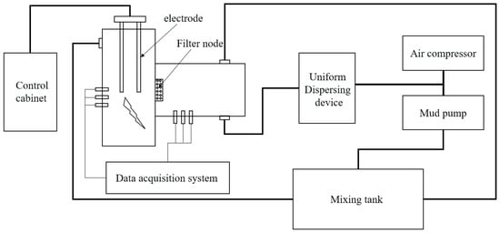
Figure 2.
Overall Design Scheme of Experimental Bench.
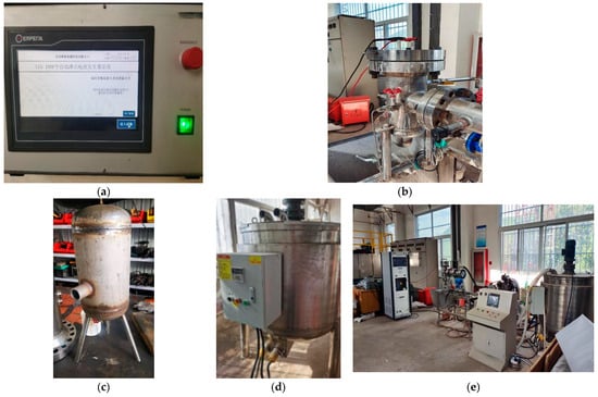
Figure 3.
Physical Picture of Experimental Device. (a) Plasma Pulse Control System. (b) T-type Experimental Chamber. (c) Homogeneous Tank. (d) Mixing Tank. (e) Overall Assembly.
The experimental system was mainly composed of a mixing system, three-phase flow generation system, impact plugging experimental chamber, discharge electrode and matching sealed fixtures, data acquisition system, and controlled plasma impact system.
The mixing system consisted of a heated 500 L stainless steel mixer with a high-speed mixer for the preparation and preservation of circulating mud for the experiment.
The three-phase flow generation system was mainly composed of a mud pump, air compressor, and homogeneous cylinder. The homogeneous solid-liquid two-phase flow of the mud pump extracted from the mixing system and the compressed air generated by the air compressor was injected into the homogeneous cylinder through the tee at the same time to form gas, liquid, and solid three-phase fluid, and the three-phase flow medium was injected after formation.
The experimental chamber of the impact plugging test cylinder adopted a T-type design, and the intersection of the horizontal chamber and the vertical chamber was provided with a filter node for installing the screen sand retaining medium. The fluid flowed out after filtering through the sand-retaining medium, and the solid particles were embedded or adhered to the surface of the sand-retaining medium, causing a blockage.
The discharge electrode was fixed on the upper cover plate of the main experimental chamber (vertical chamber) through the matching sealed fixture, and the distance between the two electrodes was 52 mm (the effective blasting length of the metal wire).
One side of the impact-unplugging test cylinder was also provided with another fluid discharge channel, and the flow rate of the channel could be controlled through the valve, which could avoid the occurrence of overpressure pumping and other conditions to ensure the safety of the experimental pressure system. On the other hand, the pressure difference between the inside and outside of the screen could be adjusted to form the environmental pressure.
2.3. Design of Experimental Parameters
In order to explore the effect of shock waves generated by plasma pulse on the blockage of a sand retaining medium, this paper compares the unplugging effect of different shock wave energy on different blockage degrees by changing the energy storage voltage and screen sand retaining precision.
The specific parameters of the experimental design are shown in Table 1.

Table 1.
Experimental running parameters for Plugging Removal.
In order to ensure the smooth progress of the screen unplugging test, it is necessary to prepare circulating mud with a certain plugging ability, stable rheological properties, and strong stability of suspended sand. The composition of the mud includes bentonite, stabilizer and quartz sand of different particle sizes (selected according to the principle of bridge), among which the bentonite selected montmorillonite content in 65~80%, can absorb 10~15 times its own water content and suspended in water; the stabilizer uses xanthan gum (XC), which has good shear dilution and stable temperature resistance, to provide a reliable suspension environment for quartz sand through the combination of two components. The base fluid formula of the mud composition is 2% bentonite +0.1% XC, and the circulating mud is composed of 100–300 mesh graded quartz sand. By comparing the pressure and flow at the outlet of a T-shaped test chamber before and after shock wave action, the plugging removal effect is evaluated.
3. Experimental Analysis of Plugging Removal Effect Evaluation
During the evaluation of the plugging removal effect of the controlled plasma shock wave, the pressure of the T-type test chamber and the pressure of the horizontal section (extended section) of the front end of the sand retaining medium (the screen plate was used in the test) were monitored by a conventional pressure sensor (low-frequency acquisition sensor), and the flow at the outlet of the T-type test chamber was monitored by an electromagnetic flowmeter. In order to facilitate unified comparative analysis, the test data curve takes the red curve as the instantaneous flow curve at the back end of the fluid outlet of the T-type test chamber (flow through the sand retaining medium), the black curve as the measured pressure curve of the T-type test chamber, and the blue curve as the pressure curve of the horizontal section (extended section) at the front end of the sand retaining medium of the T-type test chamber (the screen plate is used in the test). To be clear, the black curve is the reference curve because the shock wave formed by the plasma explosion is an instantaneous behavior, while the conventional pressure sensor has a low sampling frequency (without the function of high-frequency parameter acquisition) and cannot fully capture the pressure signal formed by the plasma shock wave. As a result, the black curve capturing the plasma shock wave pressure before and after the electric explosion is accidental. A large change occurs only after the pressure fluctuation is captured, and in other cases, the change is less.
According to the experimental data, the flow measured by the electromagnetic flowmeter at the back end of the T-type test chamber outlet is more than 2 m3/h in the case of mild blockage, and the flow rises after blasting but soon drops to 1.6~1.8 m3/h; the flow rate of moderate blockage is about 0.9–1.1 m3/h; the flow of severe state is basically 0.
3.1. Unplugging Experiment under Mild Plugging Condition
Using the controlled plasma impact unplugging test bench, the controlled plasma impact screen plate unplugging test was carried out under the condition of mild plugging. The monitoring curve is shown in Figure 4. The 200 μm precision screen plate was used to control the flow of the mud pump by opening the diverter valve, and a mild blockage state was established during the mud circulation. When the pressure of the extended section is basically stable, it can be considered to be in a mild plugging state, and the pressure of the extended section was approximately 0.91 MPa. After the cyclic balance was established, the plasma shock unplugging test was carried out by using 0.2 mm diameter copper wire under 20 kV voltage. Before the plasma explosion impact, the flow measured by the electromagnetic flowmeter at the back end of the T-type test chamber was about 2.64 m3/h. After the plasma explosion, the pressure in the extended section dropped to 0.58 MPa, with a decrease of 0.32 MPa. Moreover, it was observed that the flow at the outlet of the T-type test chamber increased significantly, and the peak flow reached 2.85 m3/h, with an increase of approximately 0.26 m3/h, which indicates that the plasma impact effectively dredges the fluid channel of the sand retaining medium and has a good plugging removal effect.
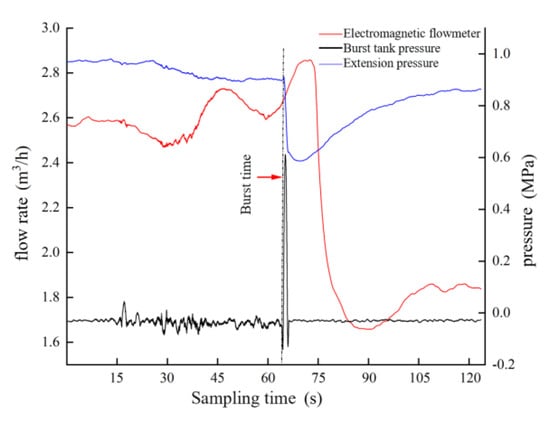
Figure 4.
Monitoring curve of the unplugging experiment under a mild blockage condition.
After plasma impact plugging removal, the electromagnetic flowmeter showed that the instantaneous flow through the sand retaining medium showed an overall trend of first increasing, then decreasing and then increasing. The instantaneous flow increased rapidly after reaching the peak value and rapidly decreased from 2.85 m3/h to 1.65 m3/h within 5 s, mainly because the channel was opened due to plasma impact plugging removal. In the extended section, more fluid carried more quartz sand into the extended section (especially considering the accumulation of quartz sand in the horizontal section in front of the sand retaining medium during the test, and the accumulation of quartz sand was obvious after being disassembled, as shown in Figure 5). After the blockage of the sand retaining medium channel was removed, the amount of quartz sand carried by the fluid increased significantly, resulting in short-term silting of the fluid channel. Subsequently, with the continuous erosion of the fluid, the blockage particles temporarily blocking the sand retaining medium channel were gradually taken away by the mud fluid, and the flow rate gradually rose. In general, the data collected by the electromagnetic flowmeter and the pressure sensor in the extended section show a trend consistency, which proves that the data are reliable and effective in plugging removal.
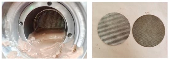
Figure 5.
Front end accumulation of the sand retaining screen plate and different specifications of the sand retaining screen plate.
3.2. Unplugging Experiment under Moderate Plugging Condition
Following the optional installation of the sand retaining medium with 200 μm precision and adjusting the displacement of the mud pump to 32 L/min through the full mud circulation, after the pressure system inside the T-type test chamber reaches a near-equilibrium state, the sand retaining medium of the test bench was in a moderate blockage state, and the controllable plasma impact plugging removal test was carried out for the sand retaining medium in the moderate blockage state. The monitoring curve of the impact unplugging process is shown in Figure 6, in which the A, B, C, and D unplugging process is completed by the plasma shock wave generated by 0.2 mm diameter copper wire at 10 kV and 25 kV voltage and the plasma shock wave generated by 0.3 mm diameter copper wire at 15 kV and 20 kV, respectively.
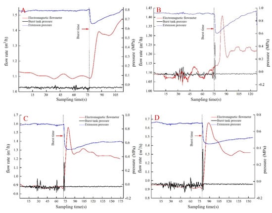
Figure 6.
Monitoring curve of the unplugging experiment under a moderate blockage condition. (A) 0.2 mm copper wire, 10 kV voltage. (B) 0.2 mm copper wire, 25 kV voltage. (C) 0.3 mm copper wire, 15 kV voltage. (D) 0.3 mm copper wire, 20 kV voltage.
After comprehensive analysis, the test results shown in Figure 6 show that the four groups of unplugging tests carried out in the case of moderate blockage have achieved good experimental results. After the occurrence of controlled plasma impact, the flow rate at the back end of the T-type test chamber increases significantly, while the pressure in the extended section decreases significantly. As the cycle continued, the pressure in the extended section also showed a trend of first decreasing and then increasing. The flow data collected by the electromagnetic flowmeter in the four groups of tests showed a trend of first increasing and then decreasing, but the value of the flow after decreasing was still significantly higher than that before the plasma shock. Limited by the ability of data acquisition, the duration of flow recovery to the moderate plugging equilibrium state could not be monitored, but a single plasma shock wave could dredge and unplug the screen plate sand retaining medium, and its unplugging effect had a lasting effect for a certain time.
As shown in Figure 6, after the plasma explosion impact, the pressure in the extended section (horizontal section) of the T-type test chamber decreased significantly, and the pressure drops in the four tests were 0.15 MPa, 0.30 MPa, 0.37 MPa, and 0.23 Mpa, respectively. The flow rate increases were 0.36 m3/h, 0.27 m3/h, 0.70 m3/h, and 0.71 m3/h, respectively, indicating that the controlled plasma impact has an obvious plugging removal effect. However, comparing the test parameters and results, it can be seen that there is no obvious correspondence between the pressure drop and the flow increase after plugging removal, and preliminary analysis can confirm that the plugging state of the sand retaining medium is an important reason for the above results.
According to the comprehensive comparison of the blocking state of the sand retaining medium during several explosions, considering the large differences between the triangular-like mesh of the sand retaining medium and the shape and particle size of the blocking medium, it can be determined that the composition and plugging degree of the blocking medium (quartz sand and clay) under each plugging state are also different. Therefore, during each plasma explosion impact, even if the same impact energy is maintained, the unplugging effect will be different. At the same time, due to the differences in the bridge and filling materials of the sand retaining medium during each test, there is no obvious correspondence between the pressure drop and the flow increase after plugging removal. Due to the limited data acquisition capability, the acquisition time during the explosion is not enough to monitor the state curve after the mud circulation is restored to stability.
3.3. Unplugging Experiment under Severe Plugging Condition
In order to simulate severe blockage, a plugging test was carried out using a circulating mud and sand retaining medium with a precision of 150 μm. The thickness of the mud cake formed on the surface of the sand retaining medium was about 1.5 mm, and the sand retaining medium of the screen plate was seriously blocked, resulting in a flow rate of 0 m3/h at the back end of the outlet of the T-type test chamber. Figure 7 shows the real-time data acquisition curve of the plasma shock wave generated by the copper wire with a diameter of 0.2 mm to unplug the sand retaining medium with a precision of 150 μm under high-pressure conditions, such as 5 kV, 10 kV, 15 kV and 20 kV in turn. As can be seen from the Figure, after the plasma explosion occurred, the blue curves showed a process of obvious decrease at first and then gradual recovery, indicating that the plasma impact caused the clogging material on the surface of the sand retaining medium to loosen or break away, the effective fluid channel of the sand retaining medium to increase, resulting in fluid pressure relief in the horizontal section of the front end of the sand retaining medium of the T-type test chamber, and the pressure reduction in the extended section. With the increase of plasma explosion energy storage voltage, the pressure drop in the extended section was 0.09 Mpa, 0.10 Mpa, 0.16 Mpa, and 0.24 Mpa, successively, indicating that the higher the energy storage voltage is, the more the effective channel of sand retaining medium increases. After the explosion impact, with the continuation of the circulation state, there was a pressure difference of about 1.0 MPa on both sides of the sand retaining medium, which can promote the sand-containing fluid to continue flowing to the sand retaining medium. The effective fluid channel of the sand retaining medium was quickly blocked again, and the blue pressure line gradually rose until the balance was re-established. The measured curve of the electromagnetic flowmeter at the back end of the outlet of the T-type test chamber did not change much before and after the plasma impact but only increased slightly, mainly because the plasma impact energy was insufficient. After the effective channel of the sand retaining medium increased for a short time, it quickly returned to the blocked state under the action of the pressure difference on both sides, resulting in an insignificant unplugging effect. It shows that the energy intensity of plasma shock should be further improved to achieve the real plugging removal effect.
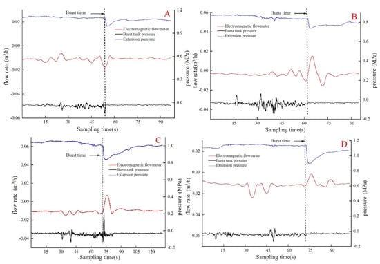
Figure 7.
Monitoring curve of the unplugging experiment under moderate blockage conditions. (A) 0.2 mm copper wire, 5 kV voltage. (B) 0.2 mm copper wire, 10 kV voltage. (C) 0.2 mm copper wire, 15 kV voltage. (D) 0.2 mm copper wire, 20 kV voltage.
3.4. Multiple Impact Unplugging Test
By using a plasma shock wave generated by a 0.2 mm copper wire at 15 kV, 20 kV, and 25 kV, respectively, the simulation evaluation test of the unplugging effect of the shock frequency on the screen plate (150μm sand retention precision) was carried out after the mud circulation formed a certain plugging state. The monitoring results of pressure, flow rate, and other data from five consecutive plasma impact plugging removals are shown in Figure 8, Figure 9 and Figure 10. It should be noted that the test process needs to first use mud circulation to create a blockage, forming a certain blockage on the sand screen plate, and then carry out five impact unplugging. Because the replacement of the arc lead wire needs to be carried out when the pump is stopping, and the continuous explosion unplugging process does not establish mud circulation, the pressure of the extended section is always at 0 MPa in the continuous implementation of the explosion process, and the pressure of the extended section is gradually increased when reopening the pump after five shocks.
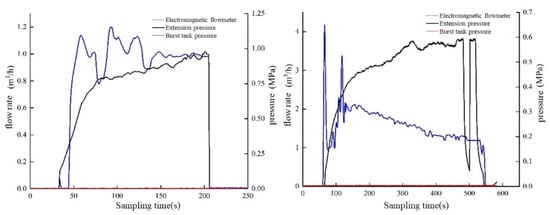
Figure 8.
Test monitoring curve of 0.2 mm + 15 kV combination for five-shock plugging removal. (a) Data curve before test. (b) Data curve after five consecutive explosions.
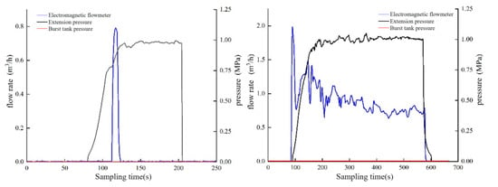
Figure 9.
Test monitoring curve of 0.2 mm + 20 kV combination for five-shock plugging removal. (a) Data curve before test. (b) Data curve after five consecutive explosions.
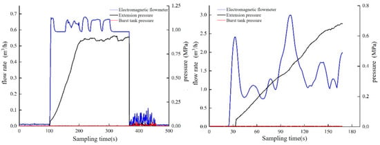
Figure 10.
Test monitoring curve of 0.2 mm + 25 kV combination for five-shock plugging removal. (a) Data curve before test. (b) Data curve after five consecutive explosions.
As can be seen from Figure 8, after the plasma shock wave formed at 15 kV acted five times, the flow rate of the electromagnetic flowmeter increased from 0.99 m3/h before unplugging to the maximum instantaneous flow rate of 4.17 m3/h. Affected by the increase of mudflow after unplugging, resulting in sand carrying and blockage formation, the instantaneous flow rate subsequently decreased to about 0.96 m3/h. Then it continued to increase to the instantaneous flow rate of 3.38 m3/h, and finally, the sand retaining medium gradually blocked, and the flow rate gradually decreased and stabilized at about 1.19 m3/h, increasing by about 20.2% compared with that before and after impact plugging removal. The differential pressure of the extended section before and after impact plugging removal was 0.95 MPa and 0.59 MPa, respectively, and the pressure of the extended section decreased significantly after unplugging.
The monitoring results of the plugging removal test on the sand retaining medium with severe blockage are shown in Figure 9. Before the impact plugging removal, the sand retaining medium was seriously blocked, and the fluid passed through briefly under the action of mud circulation and then quickly recovered to the completely blocked state with a flow rate of almost 0 m3/h. After five times of plasma impact unplugging, the electromagnetic flowmeter flow increased significantly after opening the pump again, with the highest instantaneous flow rate of 1.97 m3/h, and then due to the fluid carrying sand into the sand retaining medium, resulting in the instantaneous flow of the electromagnetic flowmeter rapidly decreased to 0.79 m3/h, and then rose to 1.47 m3/h, and then gradually decreased. When the pump stopped, the flow rate was stable at around 0.73 m3/h, and the sand retaining medium was still not completely blocked. Although the pressure difference caused by continuous impact unplugging has little change in this impact plugging test, all of which are about 1 MPa, the flow rate after impact increases significantly, indicating that the plugging removal effect is obvious. Figure 10 shows the plugging removal curve of five shocks at 25 kV. Before plugging removal, the instantaneous flow measured by the electromagnetic flowmeter was about 0.59 m3/h. After plugging removal by five shocks, the instantaneous flow first rose to 2.41 m3/h and then rose to the highest of 2.99 m3/h after a short decline. As the pressure of the extended section did not rise to the pressure before unplugging, 0.93 MPa, for a long time after plugging removal, it indicates that the five plasma shocks effectively dredge the silt-blocking hole of the sand retaining medium and achieve effective plugging removal.
Therefore, not only does the explosion impact energy have a significant influence on the plugging removal effect, but the number of plasma impacts has a significant influence on the plugging removal of the screen plate. Due to the different mud circulation sand carrying states, sand embedment state on the screen plate, and other factors, a single plasma impact will form a process of electromagnetic flowmeter flow briefly increased and then decreased after plugging removal. The flow rate after the decline is lower than that before unplugging, which means the situation is as though the impact causes the blockage on the sand retaining medium to tighten firmly, which can be understood as the impact formed plugging to a certain extent. However, after five controlled plasma shocks, the flow rate of the electromagnetic flowmeter measured by the three groups of tests is higher than that before unplugging for a long time. The results show that multiple impact unplugging can effectively avoid the occurrence of small probability situation “impact causing blockage” and help to improve the success rate and reliability of plugging removal.
3.5. Summary of Experimental Results
The results of the above four groups of experiments are summarized in Table 2. Experiments 3-1–3-4 in the T-type test bin outlet back-end electromagnetic flowmeter measurement curve before and after the plasma impact does not change much, mainly because the plasma impact energy is not enough to block the effective channel of the sand medium for a short period of time to increase the role of the pressure difference between the two sides of the rapid recovery of the blocking state, resulting in the effect of the unblocking not being obvious, indicating the need to further increase the intensity of the plasma impact energy. This indicates that the energy strength of plasma impact needs to be further improved to realize the real unblocking effect.

Table 2.
Summary of experimental results.
In the rest of the experiments, after the shock wave effect, the T-type test warehouse sand blocking media front horizontal section (extension) pressure dropped, and the T-type test warehouse outlet flow rate rose, indicating that the shock wave effect can produce the effect of unblocking, and the experimental results coincide with the expected goal.
4. Conclusions
(1) The evaluation test for the unplugging of the screen plate by controlled plasma impact fully shows that the use of controlled plasma explosion impacts can significantly reduce the pressure of the extension section and increase the flow rate of the screen plate, which proves that controlled plasma impacts can effectively dredge and unplug the screen plate in the mild and moderate unplugging state. The higher the energy storage voltage is, the higher the energy of the plasma shock wave generated. The more effective channels of the sand retaining medium are increased, the better the unplugging effect is. When the screen is in a state of severe blockage, although the situation that impact energy is insufficient to achieve increased flow through the screen will exist, the plasma impact can still briefly reduce the pressure of the extension section, indicating that the screen blockage has been solved to a certain extent. In fact, when the 0.2 mm copper wire with 25 kV voltage forms a shock wave, the flow through the screen significantly increases, which can also prove that as long as the impact energy formed is large enough, effective unplugging can be achieved;
(2) A single use of controlled plasma pulse plugging removal technology can effectively solve mild and moderate screen plate plugging states, multiple plasma impact unplugging can solve severe screen plate plugging, and the solution effect is more significant with longer maintenance time can effectively avoid the occurrence of small probability state “impact causing blockage”, help to improve the success rate and reliability of unplugging;
(3) The screen plugging removal effect is affected by many factors, such as controlled plasma impact strength, mud composition, particle blockage state of the sand retaining medium surface, etc. However, screen plugging removal can be effectively achieved by controlled plasma impact, which shows that plasma impact strength is one of the most important influencing factors. Although the experimental results confirm that the impact energy does not have a simple corresponding relationship with the plugging removal effect, the selection of appropriate shock wave generation parameters can play a positive and even decisive role in the plugging removal of the screen. Therefore, it is very important to select the matching plasma explosion generation parameters in order to achieve a better-plugging removal effect.
5. Prospect
5.1. Carry out Research on the Mechanism of Plasma Impact Decongestion
During the test, the controlled plasma impact decongestion has a better effect in multiple impacts, but after a single impact, even if the same shock wave generation parameters are used, there are occasional cases of unsuccessful decongestion. This phenomenon suggests that the clogging state of the sand retaining screen, the mud performance and sand content characteristics, and the pressure difference between the two sides of the sand retaining medium also have an impact on the decongestion effect. The pressure, flow rate, and other parameters collected during the test show a complex nonlinear relationship, and the relationship between clogging material particle size and gradation, microscopic bridge filling form, the physical effect of multiple impacts, and clogging material mosaic/seismic microscopic pattern and the effect of decongestion is still unclear, so it is urgent to carry out the corresponding theoretical research and establish the analytical model based on numerical simulation technology, so as to specify the subsequent process parameters and to select the type of downhole sand preventive tools, provide a theoretical basis for the subsequent designation of process parameters, the selection of downhole sand preventive tools, the research and development of downhole impact decongestion device, etc., and guide the setting of process parameters based on theoretical analysis.
5.2. Carry out Research on Decongestion Technology
The experiment has proved that the controlled plasma impact decongestion technology can realize the decongestion of sieve pipes under the condition of ensuring downhole safety. However, the initial exploratory test of this project is not able to propose specific decongestion process parameters for different screen tubes and different blockage conditions. Therefore, it is necessary to further optimize and modify the test rig, combine with the test mining process, downhole working conditions, reservoir environment, etc., to carry out artificial plugging tests in a graded manner, create different screen pipe plugging states, and then carry out controlled plasma impact plugging tests with appropriate impact energy, number of impacts, impact frequency, and impact distance, so as to systematically form a system of evaluation and experimental data for the formulation of on-site plugging technology, and to prepare for the on-site application.
Author Contributions
Conceptualization, B.L., L.L. and Q.X.; methodology, L.L. and L.H.; validation, F.Z., Y.Z. and B.J.; formal analysis, L.H. and L.L.; investigation, B.L.; resources, H.S.; data curation, L.H. and F.Z.; writing—original draft preparation, L.H.; writing—review and editing, L.H. and L.L.; visualization, L.H.; supervision, B.L. and Q.X.; project administration, L.L. and Q.X.; funding acquisition, Q.X. and H.S. All authors have read and agreed to the published version of the manuscript.
Funding
Natural Science Foundation of China (42072341, 42102349), Basic Research Fund of Chinese Academy of Geological Sciences (JKY21029), Basic and Applied Basic Research Project of Guangdong Province (2020B0301030003).
Data Availability Statement
Not applicable.
Conflicts of Interest
The authors declare no conflict of interest.
References
- Zhang, Y.M.; Qiu, A.C.; Zhou, H.B. Research Progress in Electrical Explosion Shockwave Technology for Developing Fossil Energy. High Volt. Eng. 2016, 42, 1009–1017. [Google Scholar] [CrossRef]
- Martin, E.A. Experimental Investigation of a High Energy Density, High Pressure Arc Plasma. Appl. Phys. 1960, 3, 255–267. [Google Scholar] [CrossRef]
- Tucker, T.J.; Toth, R.P. EBW1: A Computer Code for the Prediction of the Behavior of Electrical Circuits Containing Exploding Wire Elements; SAND-75-0041; Sandia National Lab.: Albuquerque, NM, USA, 1995; pp. 4–26. [Google Scholar]
- Lee, W.M.; Ford, R.D. Pressure measurements correlated with electrical explosion of metals in water. J. Appl. Phys. 1988, 64, 3851–3854. [Google Scholar] [CrossRef]
- Rim, G.H.; Cho, C.H.; Pavlov, E.P. Design and testing of a rotary arc gap switch for pulsed power. Plasma Sci. IEEE Trans. 2000, 28, 1491–1496. [Google Scholar] [CrossRef]
- Sarkisov, G.S.; Struve, K.W.; Mcdaniel, D.H. Effect of current rate on energy deposition into exploding metal wires in vacuum. Phys. Plasmas 2004, 11, 4573–4581. [Google Scholar]
- Pikuz, S.A.; Tkachenko, S.I.; Romanova, V.M.; Shelkovenko, T.A.; Ter-Oganesyan, A.E.; Mingaleev, A.R. Maximum energy deposition during resistive stage and overvoltage at current driven nanosecond wire explosion. IEEE Trans. Plasma Sci. 2006, 34, 2330–2335. [Google Scholar] [CrossRef]
- Rousskikh, A.G.; Oreshkin, V.I.; Labetsky, A.Y.; Chaikovsky, S.A.; Shishlov, A.V. Electrical explosion of conductors in the high-pressure zone of a convergent shock wave. Tech. Phys. 2007, 52, 571–576. [Google Scholar] [CrossRef]
- Pavlenko, A.V.; Grigor’Ev, A.N.; Afanas’ev, V.N.; Glazyrin, I.V.; Bychkov, V.B. Pressure waves generated by a nanosecond electric explosion of a tungsten wire in water. Tech. Phys. Lett. 2008, 34, 129–132. [Google Scholar] [CrossRef]
- Best, S.; Baltazar-Lopez, M.; Brandhorst, H.; Heffernan, M.; Rose, F. Pulsed powered plasma blasting for lunar materials processing. In Proceedings of the 2008 IEEE 35th International Conference on Plasma Science, Karlsruhe, Germany, 15–19 June 2008; p. 1. [Google Scholar]
- Krasik, Y.E.; Fedotov, A.; Sheftman, D.; Efimov, S.; Sayapin, A.; Gurovich, V.T.; Oreshkin, V.I. Underwater electrical wire explosion. Plasma Sources Sci. Technol. 2010, 19, 034020. [Google Scholar] [CrossRef]
- Vazhov, V.F.; Gafarov, R.R.; Datskevich, S.Y.; Zhurkov, M.Y.; Muratov, V.M. Electric-Pulse Breakdown and the Break Age of Granite. Tekh. Fiz. 2010, 55, 833–838. [Google Scholar]
- Oshita, D.; Hosseini SH, R.; Miyamoto, Y.; Mawatari, K.; Akiyama, H. Study of underwater shock waves and cavitation bubbles generated by pulsed electric discharges. IEEE Trans. Dielectr. Electr. Insul. 2013, 20, 1273–1278. [Google Scholar] [CrossRef]
- Iwasa, S.; Kira, A.; Maehara, H.; Nishi, M.; Watanabe, T.; Itoh, S.; Hokamoto, K. Pressure Measurements and Numerical Simulation of Underwater Shock Wave for Food Processing. Mater. Sci. Forum 2014, 767, 229–232. [Google Scholar] [CrossRef]
- Liu, B.; Wang, D.; Guo, Y. Effect of circuit parameters and environment on shock waves generated by underwater electrical wire explosion. IEEE Trans. Plasma Sci. 2017, 45, 2519–2526. [Google Scholar] [CrossRef]
- Han, R.; Zhou, H.; Wu, J.; Clayson, T.; Ren, H.; Wu, J.; Qiu, A. Experimental verification of the vaporization’s contribution to the shock waves generated by underwater electrical wire explosion under micro-second timescale pulsed discharge. Phys. Plasmas 2017, 24, 063511. [Google Scholar] [CrossRef]
- Han, R.; Zhou, H.; Liu, Q.; Wu, J.; Jing, Y.; Chao, Y.; Qiu, A. Generation of electrohydraulic shock waves by plasmaignited energetic materials: I. Fundamental mechanisms and processes. IEEE Trans. Plasma Sci. 2015, 43, 3999–4008. [Google Scholar] [CrossRef]
- Zhou, H.; Han, R.; Liu, Q.; Jing, Y.; Wu, J.; Zhang, Y.; Zhao, Y. Generation of electrohydraulic shock waves by plasmaignited energetic materials: II. Influence of wire configuration and stored energy. IEEE Trans. Plasma Sci. 2015, 43, 4009–4016. [Google Scholar] [CrossRef]
- Liu, Q.; Ding, W.; Han, R.; Wu, J.; Jing, Y.; Zhang, Y.; Qiu, A. Fracturing effect of electrohydraulic shock waves generated by plasma-ignited energetic materials explosion. IEEE Trans. Plasma Sci. 2017, 45, 423–431. [Google Scholar] [CrossRef]
- Li, L.; Qian, D.; Zou, X.; Wang, X. Underwater electrical wire explosion: Shock wave from melting being overtaken by shock wave from vaporization. Phys. Plasmas 2018, 25, 053502. [Google Scholar] [CrossRef]
Disclaimer/Publisher’s Note: The statements, opinions and data contained in all publications are solely those of the individual author(s) and contributor(s) and not of MDPI and/or the editor(s). MDPI and/or the editor(s) disclaim responsibility for any injury to people or property resulting from any ideas, methods, instructions or products referred to in the content. |
© 2023 by the authors. Licensee MDPI, Basel, Switzerland. This article is an open access article distributed under the terms and conditions of the Creative Commons Attribution (CC BY) license (https://creativecommons.org/licenses/by/4.0/).