Abstract
The synchronization control performance of the Fieldbus control system (FCS) is an important guarantee for the completion of multi-axis collaborative machining tasks, and its synchronization control accuracy is one of the decisive factors for the machining quality. To improve the synchronization control accuracy of FCS, this paper first makes a comprehensive analysis of the factors affecting synchronization in FCS. Secondly, by analyzing the communication model of linear Ethernet, a distributed clock compensation method based on timestamps is proposed to solve the asynchronous problem of communication data transmission in the linear ethernet bus topology. Then, based on the CANopen application layer protocol, the FCS communication and device control task collaboration method is proposed to ensure the synchronous control of multiple devices by FCS. Finally, an experimental platform is built for functional verification and performance testing of the proposed synchronization method. The results show that the proposed synchronization method can achieve a communication synchronization accuracy of 50 ns and a device control synchronization accuracy of 150 ns.
1. Introduction
With the development of Industry 4.0, intelligent, Fieldbus-based, and open industrial automation control systems have become the development direction in industrial manufacturing [1]. The FCS adopts industrial ethernet Fieldbus and standardized communication protocols, which can make the central controller (master), node controllers (slave), HMI, and other devices from a control network through a single Fieldbus. It realizes various functions such as industrial device control, data monitoring and acquisition, and open interconnection and is widely used in CNC processing, industrial robotics, and automatic production lines [2,3,4]. However, synchronization control of multiple devices in a Fieldbus network without a uniform time reference becomes an important challenge for the development of FCS [5]. In high-end equipment manufacturing industries such as numerical control processing with nano-level interpolation requirements, processing tasks need to be completed by multi-axis collaboration. The asynchronous control time of each axis will cause the actual machining path to deviate from the set path, which is related to the success or failure of the machining task [6,7]. Therefore, the synchronization accuracy of device control is the core index that determines the system’s performance. Traditional industrial control systems mostly use centralized multi-axis motion control cards with simultaneous axis control and signal output in the same processor, thus ensuring the synchronization accuracy of control [8,9]. This system architecture is not in line with the development directions of standardization, openness, and interconnection of industrial control systems.
Establishing a uniform time reference is an effective means to improve the synchronization control accuracy of the system [10]. Time synchronization methods can be broadly classified into three types according to the principle of action: high-precision clock sources, satellite timing services, and network time synchronization [11]. The high-precision clock source approach is to integrate high-precision crystal oscillation circuits in each slave station to provide additional high-precision time information [12]. However, the system will generate unacceptable cumulative errors over long periods of operation. The satellite time service method uses the high-precision clock provided by GPS satellites as the unified time reference for the system [13]. Although the time accuracy meets the industrial control requirements, the cost is too high to be suitable for industrial production applications. The network time synchronization method, represented by the precision network time synchronization method, represented by the precision time protocol (PTP), achieves time synchronization by continuously correcting and compensating the time of each slave station in the network [14]. PTP is based on a real-time ethernet Fieldbus and requires no additional hardware, making it an effective means of achieving high-precision synchronous control of FCS. More and more researchers have adopted the PTP method to improve the synchronous control performance of industrial control systems [15,16,17]. Lam D. et al. proposed a method to eliminate the frequency drift factor of the master clock crystal oscillator based on the PTP method, which improved the time synchronization accuracy of industrial ethernet by 30% [18]. Chen C. et al. designed the Modbus protocol and PTP protocol together to solve the time synchronization problem of industrial wireless sensor actuators [19]. Seo Y. et al. conducted an adaptive estimation of network noise and clock drift interference in the PTP-based system, which improved the robustness of the system synchronization clock [20]. This method of recording physical layer hardware transceiver time can obtain 100 ns level synchronization accuracy and has been widely used in major real-time Ethernet buses, such as PROFINET IRT [21], POWERLINK [22], and EtherCAT [23]. In addition, some scholars have further improved the time synchronization accuracy by using clock dynamic compensation. Buhr S. et al. proposed a timestamp measurement method combining the PI controller and PHY chip clock phase relationship, which can achieve sub-nanosecond synchronization accuracy [24]. Gong F. et al. used the Kalman filtering method to model the clock offset variation characteristics, which can improve synchronization accuracy in a temperature-variation environment [25]. Qing L. et al. proposed a dynamic delay-corrected clock synchronization algorithm for the transmission delay asymmetry between the system clock and the local clock of each slave station to improve the clock synchronization accuracy [26]. The above time synchronization methods can establish a uniform time reference and achieve high time synchronization accuracy. However, the synchronized control of industrial equipment by FCS is also influenced by its system architecture, especially the timing sequence between system communication and control behavior. For this paper, based on analyzing the factors affecting the synchronization of FCS device control, a time reference based on distributed clocks is established, and a collaborative method of communication scheduling and device control is designed to achieve high-precision synchronization control of devices.
This paper is organized as follows. In Section 2, the overall architecture and working principle of FCS are analyzed, and the influencing factors of unsynchronized control of system equipment are obtained. In Section 3, the mechanism of real-time Ethernet bus communication transmission delay is analyzed, and a distributed clock synchronization method based on timestamp compensation is proposed. In Section 4, the communication scheduling and device control timing sequence in FCS is designed based on the CANopen application layer protocol and forms the FCS device synchronization control method. In Section 5, a typical FCS experimental platform is built to verify the distributed clock synchronization accuracy and device synchronization control accuracy. Finally, Section 6 concludes this paper and points out follow-up work. The proposed FCS device synchronization control method can achieve 50 ns communication transmission synchronization accuracy and 150 ns device synchronization control accuracy. This method can improve the multi-axis collaborative processing accuracy of the FCS system and also provide a reference for the design of the synchronization control function of a similar industrial automation control system.
2. Analysis of Synchronization Factors in FCS
This section analyzes the overall system architecture and communication and data transmission principles of FCS. Then, by analyzing the timing sequence of the system control task execution, the influencing factors that lead to the desynchronization of device control by FCS are summarized, which provides a theoretical basis for the synchronization method proposed subsequently.
2.1. Basics of FCS
Typical FCS adopts an architecture that separates system logic control from device control. The master executes the user program logic and sends the control instructions to each slave through the real-time ethernet bus, and the slaves control their connected devices according to the control instructions. Figure 1 illustrates the principle of FCS architecture. The integrated development environment (IDE) is a comprehensive software platform for users to configure system hardware, edit applications, compile code, download, debug, and perform human-machine interaction. The master receives the logic code downloaded from the IDE, compiles it as a program organization unit (POU), and runs it periodically in a real-time thread of the operating system. The results of the POU operation are sent to the slaves via the real-time Ethernet bus. The slave receives the command from the master, runs the device control algorithm to control its peripherals and uploads the sensor data and its status parameters to the master. In addition, for application scenarios with network expansion requirements, the OPC-UA module of the master station can be interconnected with the cloud through the OPC-UA gateway. It is worth noting that since the master integrates all slave databases and the real-time ethernet bus adopts standardized communication protocols, the system function implementation does not depend on the hardware, reflecting the standardized characteristics of FCS. This paper focuses on the synchronization problem of FCS for device control.
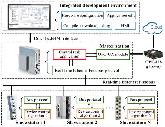
Figure 1.
Schematic diagram of the FCS architecture.
2.2. Communication and Control Principles of FCS
The control of various devices in the system by the FCS is essentially the process of periodic data interaction between master and slave in a real-time ethernet field bus. Ethernet buses can be divided into linear, tree, star, and other forms according to the topology. Due to the simple structure and high real-time data transmission characteristics of linear topology, this paper uses a linear ethernet architecture for synchronous analysis.
The communication structure and data transmission principle of FCS using linear topology are shown in Figure 2. The FCS communication structure can be divided into a physical layer, a data link layer, and an application layer. The functions and data transmission principles of each layer are as follows.
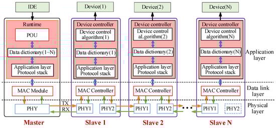
Figure 2.
Schematic diagram of the communication structure of FCS.
- Physical layer: Provide physical media for ethernet data transmission between master and slave, mainly including a PHY circuit, Category 5 cable (CAT-5), registered jack 45 (RJ45), etc. To ensure the independence of each slave in the linear topology, the physical layer of the slave includes two independent network ports.
- Data link layer: primarily consists of a MAC controller that integrates a real-time data transmission protocol. The real-time data transmission protocol processes physical layer data and transmits it directly to the application layer, bypassing the network layer and transport layer.
- Application layer: It mainly consists of the master runtime and the slave device controller. Runtime consists mainly of POU, data dictionary, and an application layer protocol stack. The POU runs the user application periodically and stores the operation results in the master data dictionary. The application layer protocol stack updates each slave data dictionary by sending ethernet frames according to the set communication period, where the master data dictionary is essentially the sum of the data dictionaries of all slaves. The slave device controller updates its own data dictionary by exchanging communication data with the MAC controller and executes device control algorithms to control its connected devices according to the data dictionary parameters.
According to the system communication architecture and data transmission principle, the typical timing sequence of system control task execution is shown in Figure 3. When the master enters cycle T, it sends one ethernet frame to obtain the status of each slave and sensor data as the input condition for POU. Then, the application layer stack sends the results of the POU to each slave. Each slave reads the data from the ethernet frame and outputs the control signal to the device after processing the protocol and running the control algorithm. The above process is repeated for each cycle until the system stops.
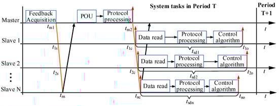
Figure 3.
Schematic diagram of a typical FCS task timing sequence.
2.3. Synchronization Error Analysis
Synchronous control mainly refers to the time consistency of the motion state of the devices in the industry controlled by FCS under the same command, such as the simultaneous action of switches and synchronous motion of motors. However, since the response time of different hardware to the command varies, this paper only considers the time synchronization of the control signal output from the slave. According to the task timing sequence analysis in Figure 3, the main factors affecting system synchronization control are as follows:
- Factor 1: Communication transmission delay. The master sends data frames containing the control commands for this cycle to the slaves at tm2. Since the communication link length of each slave is different, the time t1c~tnc for receiving ethernet frames from slaves 1~N is different. This causes the start time of the slave control task to be out of synchronization.
- Factor 2: Slave task processing time differences. After receiving the master data frame, the slave station needs to perform data reading, protocol processing, and control algorithm operation tasks. However, different functional types of slaves may receive different lengths of data and experience differences in protocol processing times and inconsistent levels of control algorithm complexity. This leads to different task processing times (tsd1~tsdn) for slaves 1~N as well, which affects the synchronization of the slave control signal output.
- Factor 3: Timeliness differences in slave feedback data. Due to the different sensor sampling times of each slave, the feedback data of each slave read by the master at tm1 via Ethernet frame may not be consistent in time. This may lead to some deviation in the POU operation results, causing the control logic to be out of synchronization.
By analyzing the above synchronization influencing factors, the main reason leading to Factor 1 is that the communication data transmission is not synchronized, while Factor 2 and Factor 3 are mainly caused by the unreasonable coordination of system communication and control tasks in time. Therefore, to eliminate the asynchronous factor of Factor 1~3, this paper focuses on the synchronization of communication transmission and the coordination of communication and device control.
3. Fieldbus Communication Synchronization Method Based on Distributed Clock
3.1. Analysis of Communication Transmission Delay
Figure 4 shows the communication delay principle between two adjacent slaves A and B in a linear network consisting of one master and N slaves. During the forward transmission, the Ethernet frame is received by the PHY0_rx port of slave A, then processed by the MAC controller and sent out from the PHY1_tx port. The PHY0_rx port of slave B receives the data sent from the PHY1_tx port of slave A and performs the same processing as slave A. When the ethernet frame is transmitted to the slave N, it starts to be transmitted in the reverse direction and finally returns to the master.
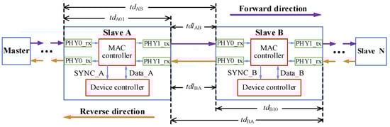
Figure 4.
Schematic diagram of the communication transmission delay in a linear network.
During forward transmission, after the Ethernet frame arrives at slave A, the MAC controller needs to perform data reading, feedback data uploading, and retransmission operations. The time consumed in this process is called station processing delay, which is represented by tdA01. The time consumed for the ethernet frame to travel between the PHY_tx port of slave A and the PHY0_rx port of slave B is called the cable transmission delay and is denoted by tdlAB. Therefore, the overall delay time tdAB for two adjacent slaves A and B to receive Ethernet frames sent by the master can be expressed as follows.
Similarly, during reverse transmission, the transmission delay tdBA of slave stations A and B can be expressed as follows:
The above analysis shows that communication frame transmission in a linear network is mainly affected by cable transmission delay and station processing delay, resulting in different times for each slave station to receive the same communication frame. The phenomenon is objective and unavoidable. However, the communication data ultimately serves the device controller. A SYNC output signal with adjustable output time is designed in the MAC controller. The synchronization of SYNC signal generation is ensured by accurately measuring the cable transmission delay and station processing delay of each slave station and compensating for the time of the SYNC output signal. The device controller of each slave station reads communication data from the MAC controller according to the SYNC signal, which ensures synchronized communication.
3.2. Method of Communication Delay Measurement
Define the first slave connected to the master as the reference slave. The communication delay of each other slave is based on the reference slave. To analyze the time consumption relationship of the communication transmission process more intuitively, a linear network communication transmission model is established, as shown in Figure 5.
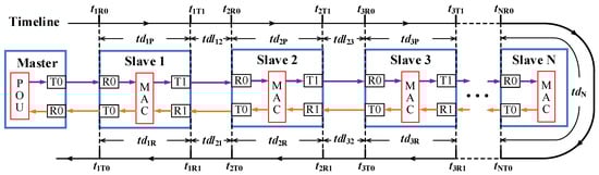
Figure 5.
Communication transmission delay model for the linear network.
The model describes the time relationship of the communication frame transmitted in the Fieldbus network consisting of 1 master and N slaves. The definition of each parameter in Figure 5 is shown in Table 1.

Table 1.
Parameter definition table for communication transmission delay model.
According to the model analysis, the cable transmission delay and station processing delay are calculated as follows.
- Cable transmission delay calculation
The connection distance between slave stations in industrial applications is generally short, and the transmission asymmetry time of CAT-5 is about 0.1 ns/m, which can be considered symmetrical for cable transmission delay. Therefore, for the adjacent slaves i and j, the following relationship is satisfied.
Considering the different time bases of each slave, let the time deviation between slave 1 and slave 2 be toffset12, and then the cable transmission delay between slave 1 and slave 2 can be represented by Equation (4).
Substituting Equation (3) into Equation (4), the cable transmission delay between slave 1 and slave 2 can be obtained as:
The time deviation toffset12 in the result of Equation (5) is counteracted. Without loss of generality, the cable transmission delay from slave i to the reference slave is the sum of the cable transmission delays between all neighboring slave nodes in its forward link. The calculation method is shown in Equation (6).
- 2.
- Station processing delay calculation
The station processing delay reflects the time that the communication frame stays inside the slave station. It is the total time from the moment when the read signal of the PHY chip at the receiving port is valid to the moment when the write signal of the PHY chip at the sending port is valid. Since all station processing occurs within the slave station, it can be recorded directly using local time. According to the model, the station processing delay of slave station i can be calculated as follows:
When communication frames are transmitted in the reverse direction, the slave stations do not exchange data. Therefore, only tdiP is considered in the station delay compensation. All station processing delays td1i from station i to the reference slave can be expressed by Equation (8).
According to the calculation results of Equations (6) and (8), it is easy to obtain the communication delay between slave station i and the reference slave station. The master can write the cable transmission delay and station processing delay of each slave into each MAC controller as important parameters for slave clock synchronization.
3.3. Distributed Clock Synchronization
In the Fieldbus network, the local clock of each slave station is affected by the power-on time, environment temperature, crystal precision, and other conditions showing dynamic change characteristics. The distributed clock makes the system time consistent by correcting the time of each slave to match the moment of the reference slave. Figure 6 shows the principle of distributed clock compensation.
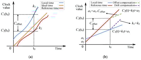
Figure 6.
Schematic Diagram of Distributed Clock Compensation: (a) actual curve of local time and reference time slave; (b) curve of local time and reference time after compensation.
In Figure 6a, the local and reference clocks exhibit dynamic changes with time. The offset of the local and reference clocks at time t0 is Coffset. In addition, there may be a difference between the change rate of the local clock k1 and the change rate of the reference clock k2 at t0. The difference in the change rate of the clock will cause the clock curve to drift and may cause Coffset to increase over time.
Although the clock curve is not an ideal straight line, it can be approximated as a straight line over a short period, as shown in Figure 6b. Calculate the difference between the offset value and the drift value of the local clock and the reference clock, and compensate the local clock to synchronize the local clock with the reference clock.
- Clock offset compensation
The basic idea of clock offset compensation is to add the offset Coffset(t) of the local clock and reference clock at time t to the local clock as the compensation value. The expression of the local time Clocal of the slave station is as Equation (9).
where k is the initial value of the local time change rate, and a is the initial value of the local time.
The ethernet frame containing the clock compensation message sent by the master arrives at the reference slave at tref time. The reference slave local time, Cref(tref), is written into the data frame as timestamp information. When the frame arrives at slave i at time ti, the time deviation Coffset(ti) between slave i and the reference slave can be expressed as Equation (10).
The local time Cref(ti) of the reference slave at time ti cannot be directly obtained from slave station i. However, Cref(ti) can be calculated using timestamp information, Cref(tref), and Equations (6) and (8), as follows:
where tdl1i and td1i are the cable transmission delay and station processing delay between slave i and the reference slave, respectively.
According to Equations (9)–(11), the time deviation Coffset(ti) of slave i from the reference slave at time ti can be obtained as follows:
The value of Coffset(ti) was added to the initial value of local time and used as the new initial synchronization time anew. In this way, the new local time can be formed as follows:
- 2.
- Clock drift compensation
The clock drift phenomenon is mainly caused by the difference between the slave local clock change rate and the reference slave change rate. Periodically calculating the reference slave time change rate and using it as the slope of the local clock curve is an effective method for drift compensation.
Let tk and tk+1 be the times at which the two clock compensation messages arrive at slave i, respectively. The local time change rate ki of the slave during this period can be expressed as follows:
According to Equation (11), the reference slave time change rate kref can also be obtained as Equation (15).
The change rate of local time can be corrected to knew according to the relationship of the ratio of kref and ki. The local time after drift compensation and offset compensation can be expressed as Equation (16).
In summary, the use of time drift and offset compensation methods to establish a system-distributed clock can make each slave and the reference slave time maintain a high degree of synchronization and solve the bus communication transmission delay problem.
4. Collaborative Method of System Communication and Device Control
In an architecture where logic control and device control are separated, ensuring the temporal rationality of master communication tasks and slave control tasks is the key to synchronous control of FCS. This section proposes a system communication and device control collaboration method based on the CANopen application layer protocol. Through the design of the system communication data transmission method, communication scheduling behavior, and device control timing sequence, the synchronization of device control by FCS is ensured.
4.1. CANopen Data Transmission Method over Ethernet Links
The transmission mode of the CANopen protocol is based on the CAN bus, and each communication frame can only carry data information for one slave station. In this way, the master station needs to send multiple communication frames at a time to complete the command transmission within a communication cycle. There is no doubt that this will cause the time spent acquiring communication data from each slave station to be out of sync.
To ensure synchronous transmission of communication data, each slave’s data can be packaged into different messages and integrated into ethernet frames. However, this method will generate more invalid data in ethernet frames, such as message headers, interrupt responses, etc. Therefore, this section uses the data mapping method to design the ethernet data frame format to improve the data transmission efficiency of the communication frame and to achieve more slave data transmission in the limited Ethernet data space. The mapping principle is shown in Figure 7.
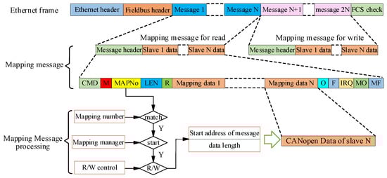
Figure 7.
Schematic diagram of the Ethernet frame data structure.
In Figure 7, the messages sent by the master to each slave are combined into one read message, and the upload messages of each slave are combined into one write message. The slave reads and writes the mapped message using the configuration information, such as the mapping number, starting address, and data length. This data mapping transmission method improves the data transmission efficiency of ethernet frames and allows for a larger loading space for CANopen protocol data.
In the mapping message, the data of each slave is organized according to the standard CANopen data frame format, which consists of 11 bytes of space for Cobid, data length, and data information, respectively. The format of the CANopen frame transmission in the mapping message is shown in Figure 8.
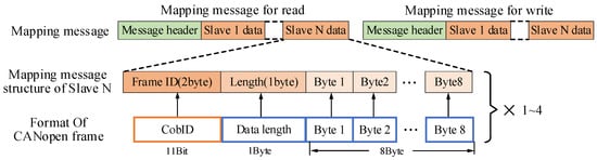
Figure 8.
Schematic diagram of CANopen frames integrated with the mapping message.
CANopen specifies a variety of communication objects, including NMT, SDO, PDO, etc. The number of CANopen frames required for NMT, SDO, and PDO transmission varies, and the master needs to configure different lengths of read/write message mapping space according to the type of frames to be sent. NMT and SDO only need one CANopen frame space for a single transmission. However, PDO can be configured into 1–4 groups as required, including TPDO and RPDO. When composing ethernet frames, the master needs to reserve data space of the appropriate size according to the number of PDOs of each slave. In this way, the CANopen application layer data can be transmitted over the ethernet Fieldbus.
4.2. System Communication Scheduling Method
To ensure real-time communication, the answer to the current command in the linear network can only be transmitted back through the next ethernet frame. This delayed response mechanism is not conducive to the timely upload of slave data, which may cause the output logic of the POU to be out of sync. To make the POU and the device control algorithm time reasonable, this section designs the communication frame scheduling methods for system initialization, pre-operation, and operation status according to CANopen.
- Initialization state scheduling
In this stage, after the slave completes the initialization of the protocol stack, a bootup frame containing the slave node information will be generated and written to the MAC controller. The master sends a query frame to read the bootup information of each slave in the bus network. If the node information conforms to the hardware configuration file, it will enter the pre-operation state. If it does not conform, it indicates that the bus connection or slave station is abnormal.
- 2.
- Pre-operation state scheduling
In this state, the master performs status queries, parameter configuration, PDO configuration, and other operations on the slave station through SDO. Figure 9 shows the communication timing sequence of the slave device controller, MAC controller, and POU in the pre-operation state.
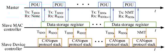
Figure 9.
Schematic diagram of system communication timing sequence in the pre-operation state.
After entering the pre-operation state, the master sends the TSDO1 command to each slave. At this time, the read-back information may still be bootup information, which can be ignored. After the device controller of the slave reads the TSDO1 data in the MAC controller, it is processed by the CANopen protocol stack, and the SDO response RSDO1 is written to the MAC controller. When the master sends the TSDO2 command, it can read back the RSDO1 information in the MAC controller. At the end of the pre-operation state, the master station sends an NMT command to read back RSDOn information and switch the slave station to the operation state.
- 3.
- Operation state scheduling
The communication data on operation status is time-sensitive and closely related to the POU control logic. In this state, the master periodically sends a synchronization frame (syncf) to read the RPDO information of the slave and sends instructions after the POU operation to each slave through TPDO frames. The key to system synchronization control is to ensure that the POU input parameters are the latest data of the slave in this cycle and that the POU output instructions can be executed by the slave in this cycle.
Figure 10 shows the system communication timing sequence in the operating state. The communication scheduling task in a period can be divided into three stages, and the tasks of each stage are the same. Taking communication period 1 as an example, the communication scheduling process of master and slave at each stage is described in detail below.
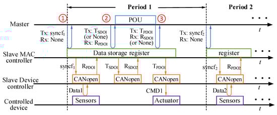
Figure 10.
Schematic diagram of system communication timing sequence in operation.
- Stage 1: At the beginning of communication period 1, the master sends syncf1 to each slave station, and the read-back information is ignored. After the device controller of the slave reads syncf1, it updates the sensor data and writes it to the MAC controller through the RPDO1 frame of CANopen, waiting for the next frame to be read back.
- Stage 2: The master sends a query frame to read back the RPDO1 information in the MAC controller of each slave. If an SDO frame is requested to be sent during the period, the query frame is replaced by a TSDO1 data frame. After reading back RPDO1, the master takes the RPDO1 data as a POU input parameter and runs POU.
- Stage 3: The master sends the POU operation result through the TPDO1 frame. The slave runs the device control algorithm according to the instructions of TPDO1 and controls the actuator.
The above communication scheduling mechanism can ensure the logic and independence of sensor data acquisition, POU operation, and the device control algorithm in time.
4.3. Slave Control Timing Sequence Design
The CANopen-based communication scheduling method provides a good timing sequence reference for the implementation of the slave control algorithm. Combined with the distributed clock synchronization signal SYNC, the execution time of each slave task can be unified. The timing sequence relationship between system communication and slave station control tasks under operation status is shown in Figure 11.
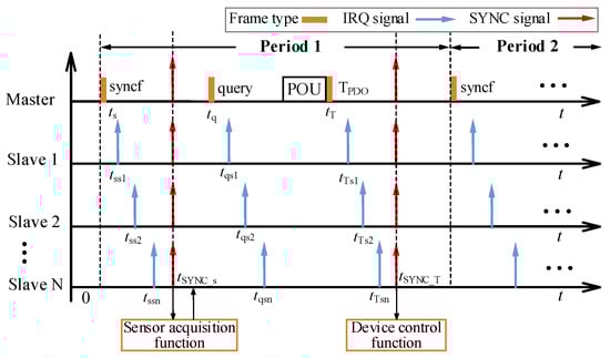
Figure 11.
Slave control task timing sequence diagram in operation state.
In Figure 11, the MAC controller of each slave station will generate an IRQ signal after receiving the communication frame, informing the device controller that the communication data can be read. Due to the communication transmission delay, the interrupt signal IRQ time generated by each slave MAC controller after receiving the communication frame is inconsistent. However, the distributed clock can be used to generate a SYNC signal simultaneously after the communication frame is received by all slaves. The SYNC signal of the synchronization frame is used as the trigger for the sensor acquisition function of each slave, and the SYNC signal of the TPDO frame is used as the trigger for the device control algorithm.
It is worth noting that when setting the SYNC generation time, it must be ensured that the last slave in the Fieldbus has finished receiving the data frames. Otherwise, it will cause some slaves to be out of synchronization with the control commands of other slaves. According to Equations (6)–(8), the SYNC signal generation time tSYNC of any frame should satisfy the following condition:
where n is the last slave node number, and tsend is the time when the communication frame is received by the reference slave.
Due to the different complexity of the control algorithms of the slave, the execution time is quite different. To have the same time for each slave to output control signals, the control signal generated by the control algorithm in this cycle is output at the same time as the SYNC signal in the next cycle, which can ensure output synchronization. Figure 12 shows the timing sequence principle of slave communication and control task execution.
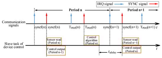
Figure 12.
Slave control task timing sequence diagram in operation state.
During period n, the slave station executes the sensor reading task in this period according to the SYNC signal of syncf(n) and simultaneously outputs the control signal of the previous period. When the SYNC signal of the TPDO(n) frame is valid, the slave executes the control algorithm of this cycle and latches the output signal. The latched control signal will be output when the SYNC signal of the syncf(n + 1) frame of the n + 1 period is valid. The synchronous output method after the latch will generate the output delay of tsdelay. However, the communication period of a real-time Ethernet bus-based control system is generally in the order of milliseconds, and tsdelay does not affect the control performance of the system.
In summary, the logical synchronization of the system and the synchronization of the device control can be ensured by the collaborative design of the system communication scheduling and device control tasks.
5. Experiment
In this section, an experimental platform is constructed to verify the high-precision synchronization control method of the device proposed in this paper. Figure 13 shows the self-developed FCS experimental platform, which consists of a power supply, a master station, four slave stations, an HMI display, and a PC with IDE installed. The master adopts Hi3559a as a CPU chip that integrates the Linux Ubuntu16.04 operating system and forms a linear network with 4 slaves via ethernet. The slave uses the FPGA of HME-P1P6060N0TF784C as the MAC controller and the Soc chip HME-M7A12N0F484I7 with the integrated cortex-m3 core as the device controller. The clock synchronization protocol proposed in this paper is designed in Verilog, and integrated in the HME-P1P60600N0TF784C chip. It forms the Ethernet physical layer with the general-purpose 100 M PHY chip, network transformer, and M12 industrial connector. The Codesys software is installed on the PC as the system IDE. The HMI display provides the human-machine interaction interface. The power supply provides 24 V DC power to the master station and four slave stations. The device interface of each slave is led from the interface board to facilitate oscilloscope observation of the distributed clock synchronization signal SYNC as well as the device control signal.
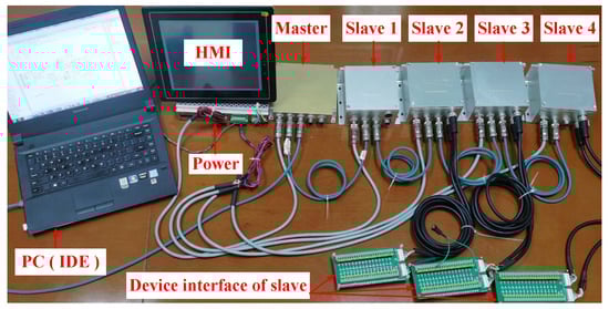
Figure 13.
FCS experimental platform diagram.
A multi-axis robot application scenario is simulated using the experimental platform shown in Figure 13. The master controls each slave to generate the orthogonal pulse signal required by the robot joint driver at the same time to control each joint axis. Set the system communication cycle to 1 ms, and design the POU logic in the IDE to make the slave generate 20 pulses with a frequency of 50 KHz in each communication cycle.
The SYNC signal is directly generated by the distributed clock, and the time error of the SYNC signal of each slave directly reflects the synchronization accuracy of the distributed clock. After the system is powered on and enters the operation state, the SYNC signals of slave 1~4 are shown in Figure 14.
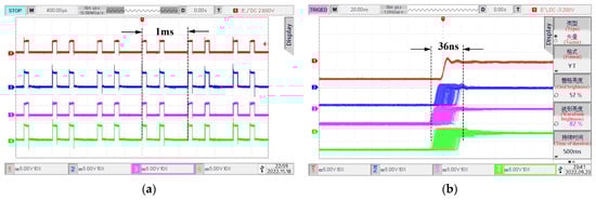
Figure 14.
System distributed clock synchronization test result diagram: (a) SYNC signal waveform of each slave under a 400 μs time scale; (b) SYNC signal waveform of each slave under a 20 ns time scale.
Figure 14a shows the oscilloscope waveform of the SYNC signal of each slave on a 400 μs time scale. It can be found that the SYNC signal generates two edge jumps within 1 ms, representing the synchronization frame and TPDO frame, respectively. SYNC signals show consistency and periodicity in time. Figure 14b shows the rise edge detail of the SYNC signal under a 20 ns time scale. The rise time of the SYNC signal of each slave has deviation and jitter, and the jitter time error is about 36 ns. This time jitter is caused by uncertainty factors such as timestamp measurement accuracy, data transmission delay jitter, PHY chip data reception, transmission jitter, etc.
Time synchronization of the device control signal output of each slave is the key to multi-axis coordinated control. Use the oscilloscope to observe the pulse output ports of each slave station to test the synchronization performance of the equipment. The test results are shown in Figure 15.
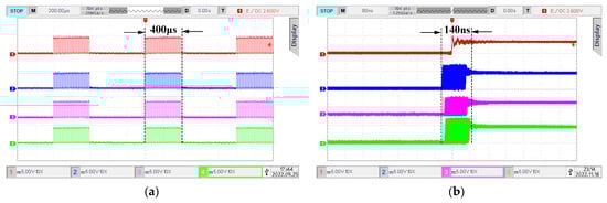
Figure 15.
System device control synchronization test result diagram: (a) pulse output waveform of each slave under a 200 μs time scale; (b) pulse output waveform of each slave under a 80 ns time scale.
When the time scale of the oscilloscope is 200 us, slave 1~4 generates pulse signals with a total time width of 400 us in a communication cycle. The pulse output time of each slave is the same, and the number and frequency of pulses are the same as the logic settings of the master station, as shown in Figure 15a. When the time scale of the oscilloscope is amplified to 80 ns, it can be observed that there is deviation and jitter in the jumping time of each slave station pulse signal, and the overall jitter time range is about 140 ns, as shown in Figure 15b. According to the slave control timing sequence in Section 4, the time error of the output pulse of each slave shall be theoretically consistent with the SYNC signal error. However, because the pulse output involves MCU software modules and related hardware circuits, the synchronization error is larger than the theoretical value.
To verify the independence of system synchronization accuracy and running time, the experimental platform in Figure 13 was tested for seven consecutive days. The synchronization error of the SYNC signal and pulse output signal is tested several times a day, and its maximum value is recorded. The experimental results are shown in Table 2.
Table 2.
Synchronization performance test table during continuous system operation.
From the test data in Table 2, it can be seen that the system communication transmission synchronization error and device control synchronization error remain stable during the continuous operation of the system. The fluctuation range of communication transmission synchronization error is 4 ns, and the fluctuation range of device control synchronization error is 8 ns.
In summary, the synchronization control method proposed in this paper can ensure that the synchronization accuracy of FCS communication transmission is less than 50 ns and the synchronization accuracy of device control is less than 150 ns.
6. Conclusions
This paper focuses on the research of the device synchronization control method of a Fieldbus control system. Through the analysis of the composition principle of typical FCS and the communication control process of FCS based on a real-time ethernet field bus, it is concluded that the main factors affecting the synchronization control of the system are the communication transmission delay and the desynchrony of communication and control logic. To eliminate the impact of communication transmission delay on synchronization control, this paper analyzes the communication transmission mechanism in the linear ethernet topology and uses timestamps to measure the cable transmission delay and static processing delay. The distributed synchronization clock of the system is established according to the delay measurement results, which provides a unified time benchmark for each slave of the system. In addition, aiming at the problem that the communication tasks and control logic of the system are not synchronized, this paper uses the CANopen application layer protocol to design the system communication data transmission, communication task scheduling, and device control timing, forming a collaborative method of system communication and device control. Finally, a typical FCS experimental platform is built to verify the synchronization control method proposed in this paper. The experimental results show that the synchronization method proposed in this paper can make the communication transmission synchronization accuracy less than 50 ns and the equipment control synchronization accuracy less than 150 ns. The synchronization method proposed in this paper meets the requirements of industrial applications for the synchronization accuracy of the control system and provides a reference for FCS synchronization-related research. In the future, we will further study the improvement of synchronization accuracy.
Author Contributions
Conceptualization, L.C. and D.F.; methodology, L.C. and D.F.; software, L.C.; validation, L.C., J.Z. and N.C.; formal analysis, D.F.; investigation, L.C.; resources, D.F. and N.C.; data curation, J.Z.; writing—original draft preparation, L.C.; writing—review and editing, L.C.; visualization, N.C.; supervision, D.F.; project administration, D.F.; funding acquisition, N.C. All authors have read and agreed to the published version of the manuscript.
Funding
This research was funded by the National Natural Science Foundation of China (Grant No. U19A2072).
Data Availability Statement
Not applicable.
Conflicts of Interest
The authors declare no conflict of interest.
References
- Zeng, P.; Wang, Z.; Jia, Z.; Kong, L.; Li, D.; Jin, X. Time-slotted software-defined Industrial Ethernet for real-time Quality of Service in Industry 4.0. Futur. Gener. Comput. Syst. 2019, 99, 1–10. [Google Scholar] [CrossRef]
- Erwinski, K.; Paprocki, M.; Grzesiak, L.M.; Karwowski, K.; Wawrzak, A. Application of Ethernet Powerlink for Communication in a Linux RTAI Open CNC system. IEEE Trans. Ind. Electron. 2012, 60, 628–636. [Google Scholar] [CrossRef]
- Wang, S.; Ouyang, J.; Li, D.; Liu, C. An Integrated Industrial Ethernet Solution for the Implementation of Smart Factory. IEEE Access 2017, 5, 25455–25462. [Google Scholar] [CrossRef]
- Danielis, P.; Skodzik, J.; Altmann, V.; Schweissguth, E.; Golatowski, F.; Timmermann, D.; Schacht, J. Survey on real-time com-munication via ethernet in industrial automation environments. In Proceedings of the 2014 IEEE Emerging Technology and Factory Automation, Barcelona, Spain, 16–19 September 2014. [Google Scholar]
- Liang, G.; Li, W. Some Thoughts and Practice on Performance Improvement in Distributed Control System Based on Fieldbus and Ethernet. Meas. Control. 2016, 49, 109–118. [Google Scholar] [CrossRef]
- Jia, Z.-Y.; Ma, J.-W.; Song, D.-N.; Wang, F.-J.; Liu, W. A review of contouring-error reduction method in multi-axis CNC machining. Int. J. Mach. Tools Manuf. 2018, 125, 34–54. [Google Scholar] [CrossRef]
- Li, Y.-H.; Zheng, Q.; Yang, L. Multi Hydraulic Motors Synchronized Control Based on Field Bus with FlexRay Protocol. Adv. Sci. Lett. 2012, 9, 603–608. [Google Scholar] [CrossRef]
- Zhong, G.; Shao, Z.; Deng, H.; Ren, J. Precise Position Synchronous Control for Multi-Axis Servo Systems. IEEE Trans. Ind. Electron. 2017, 64, 3707–3717. [Google Scholar] [CrossRef]
- Shi, T.; Liu, H.; Geng, Q.; Xia, C. Improved relative coupling control structure for multi-motor speed synchronous driving system. IET Electr. Power Appl. 2016, 10, 451–457. [Google Scholar] [CrossRef]
- Liang, G. Control and communication co-design: Analysis and practice on performance improvement in distributed meas-urement and control system based on fieldbus and Ethernet. ISA Trans. 2015, 54, 169–192. [Google Scholar] [CrossRef]
- Kurata, N. Development and application of an autonomous time synchronization sensor device using a chip scale atomic clock. Sens. Transducers 2018, 219, 17–25. [Google Scholar]
- Chen, R.; Liu, Y.; Li, X.; Fan, D.; Yang, Y. High-precision time synchronization based on common performance clock source. In Proceedings of the 2019 14th IEEE International Conference on Electronic Measurement & Instruments (ICEMI), Changsha, China, 1–3 November 2019. [Google Scholar]
- Guo, H.; Crossley, P. Design of a Time Synchronization System Based on GPS and IEEE 1588 for Transmission Substations. IEEE Trans. Power Deliv. 2016, 32, 2091–2100. [Google Scholar] [CrossRef]
- Bello, L.L.; Steiner, W. A Perspective on IEEE Time-Sensitive Networking for Industrial Communication and Automation Systems. Proc. IEEE 2019, 107, 1094–1120. [Google Scholar] [CrossRef]
- Pedretti, D.; Bellato, M.; Isocrate, R.; Bergnoli, A.; Brugnera, R.; Corti, D.; Corso, F.D.; Galet, G.; Garfagnini, A.; Giaz, A.; et al. Nanoseconds Timing System Based on IEEE 1588 FPGA Implementation. IEEE Trans. Nucl. Sci. 2019, 66, 1151–1158. [Google Scholar] [CrossRef]
- Idrees, Z.; Granados, J.; Sun, Y.; Latif, S.; Gong, L.; Zou, Z.; Zheng, L. IEEE 1588 for Clock Synchronization in Industrial IoT and Related Applications: A Review on Contributing Technologies, Protocols and Enhancement Methodologies. IEEE Access 2020, 8, 155660–155678. [Google Scholar] [CrossRef]
- Popescu, D.A.; Moore, A.W. Measuring Network Conditions in Data Centers Using the Precision Time Protocol. IEEE Trans. Netw. Serv. Manag. 2021, 18, 3753–3770. [Google Scholar] [CrossRef]
- Lam, D.K.; Yamaguchi, K.; Nagao, Y.; Kurosaki, M.; Ochi, H. An improved precision time protocol for industrial WLAN communication systems. In Proceedings of the 2016 IEEE International Conference on Industrial Technology (ICIT), Taipei, Taiwan, 14–17 March 2016. [Google Scholar]
- Chen, C.-H.; Lin, M.-Y.; Tew, W.-P. Wireless fieldbus networking with precision time synchronization for a low-power WSAN. Microprocess. Microsyst. 2022, 90, 104509. [Google Scholar] [CrossRef]
- Seo, Y.; Son, K.; An, G.; Nam, K.; Chang, T.; Kang, S. Improved Time-Synchronization Algorithm Based on Direct Compen-sation of Disturbance Effects. Sensors 2019, 19, 3499. [Google Scholar] [CrossRef]
- Gutierrez-Rivas, J.L.; Torres-Gonzalez, F.; Ros, E.; Diaz, J. Enhancing White Rabbit Synchronization Stability and Scalability Using P2P Transparent and Hybrid Clocks. IEEE Trans. Ind. Inform. 2021, 17, 7316–7324. [Google Scholar] [CrossRef]
- Romanov, A.; Slepynina, E. Real-time Ethernet POWERLINK communication for ROS. Part II. Hardware and software. In Proceedings of the 2020 Ural Smart Energy Conference (USEC), Ekaterinburg, Russia, 13–15 November 2020. [Google Scholar]
- Paprocki, M.; Erwiński, K. Synchronization of Electrical Drives via EtherCAT Fieldbus Communication Modules. Energies 2022, 15, 604. [Google Scholar] [CrossRef]
- Buhr, S.; Kreisig, M.; Protze, F.; Ellinger, F. Subnanosecond Time Synchronization Using a 100Base-TX Ethernet Transceiver and an Optimized PI-Clock Servo. IEEE Trans. Instrum. Meas. 2020, 70, 1–8. [Google Scholar] [CrossRef]
- Gong, F.; Sichitiu, M.L. Temperature compensated Kalman distributed clock synchronization. Ad Hoc Netw. 2017, 62, 88–100. [Google Scholar] [CrossRef]
- Qing, L.; Xinyang, R. IEEE 1588 and a dynamic delay correction clock synchronization algorithm. In Proceedings of the 2019 IEEE 5th International Conference on Computer and Communications (ICCC), Chengdu, China, 6–9 December 2019. [Google Scholar]
Disclaimer/Publisher’s Note: The statements, opinions and data contained in all publications are solely those of the individual author(s) and contributor(s) and not of MDPI and/or the editor(s). MDPI and/or the editor(s) disclaim responsibility for any injury to people or property resulting from any ideas, methods, instructions or products referred to in the content. |
© 2023 by the authors. Licensee MDPI, Basel, Switzerland. This article is an open access article distributed under the terms and conditions of the Creative Commons Attribution (CC BY) license (https://creativecommons.org/licenses/by/4.0/).