1. Introduction
The reason involute spline couplings are widely used in aviation drive systems is that the connection of the spline couplings can meet the connection requirements of larger torque and higher speed; second, its assembly mode is a coaxial connection to ensure good guidance and neutrality between the shaft parts and the main shaft of the power system [
1]. There are gaps between floating spline tooth surfaces, between internal and external tooth tops, and between adjacent tooth roots; it is required to select the tooth profile corresponding to the backlash, which is different from the centering method of the fixed involute spline. This kind of non-centering connection allows a certain axis displacement between the spline shaft and the spline sleeve during operation to compensate for the design, manufacturing, processing, and assembly errors [
2]. When the spline coupling transmits torque, there is slight relative movement between the internal and external splines due to the existence of backlash. On the other hand, the axial floating of the spline couplings is caused by the existence of axial force or the change in the external load. Under the combined effect of these two factors, the tooth surface wear failure of the aviation gradually floating open spline couplings is extremely serious. Because the axial floating distance is not parallel to the axis, the lubrication is not sufficient, and the wear particles easily accumulate, causing serious wear on the tooth surface. The problem of premature failure of components caused by excessive wear of floating splines has occurred many times in the aviation drive system, which is one of the key technologies restricting the improvement of the life and reliability of drive components.
Xue et al. [
3,
4] studied the wear of aviation floating involute spline couplings under different tooth surface wear factors, loads, and operating cycles by using the finite element method and designed a planar spline coupling structure that can simulate the floating involute spline couplings to verify theoretical research. Tang [
5] studied the influence of different lubrication methods and surface treatment on the wear of the spline couplings of the helicopter reducer through finite element simulation and carried out simulation analysis. The conclusion is that the stress distribution of the spline tooth surface is relatively uniform under different friction factors. With the increase in dynamic friction coefficient, the friction between spline contact surfaces increases, the average contact stress of tooth surface increases with the increase in the friction coefficient, and the relative sliding speed of spline tooth surface decreases with the increase in the friction coefficient.
Xu et al. [
6,
7] verified the accuracy of the optimized Archard wear calculation model by combining pin on disk wear test with ANSYS and then studied the influence of backlash, including angle and modification amount on tooth surface wear. They used mathematical models to fit the three to obtain the best involute spline couplings parameters to achieve the role of wear reduction and wear resistance. As for the research on the load distribution on the tooth surface of the spline couplings, Tan et al. [
8,
9] researched the load distribution of the involute spline couplings in the case of misalignment. The research shows that the radial misalignment of the involute spline couplings is more serious than the axial misalignment, and the radial misalignment plays a major role in the case of the combination of the two misalignments. Wei et al. [
10,
11] established the finite element model of the involute spline couplings of the shield shaft and studied the stress distribution on the tooth surface of the spline couplings in the working process; the research showed that when the spline couplings transmit the load, there is stress concentration on the tooth surface along the axial and radial directions, the spline teeth are modified along the tooth profile and tooth direction, respectively, and the involute spline couplings after the modification are simulated in a limited way. The research shows that the stress concentration on the tooth surface of the involute spline couplings after the modification is significantly improved, and the reliability of the involute spline couplings of the shield shaft is improved.
Many scholars have also carried out research on this topic. Ratsimba et al. [
12] proposed a prediction method for fretting wear of spline couplings based on the Archard model. McColl [
13] proposed a finite element method to calculate fretting wear based on the modified Archard equation, but it simulates the wear process of a pin disk structure. At present, when calculating the tooth surface wear of the involute spline couplings, the Archard wear formula is often used, and the model in the research content has also been simplified. The existing Archard wear formula is not suitable for calculating the wear depth of the aviation floating involute spline couplings. Baker et al. [
14] studied the working process of the straight tooth spline couplings, established the finite element model of the straight tooth spline couplings, analyzed the simulation results of the spline couplings under the combined working conditions of axial load, torque, and bending moment, and studied and analyzed the distribution of contact stress on the tooth surface. Leen et al. [
15,
16,
17] took helical spline couplings as the research object, explored the influence of axial load and torque on the distribution of tooth surface contact stress of helical spline couplings, and carried out relevant research on the influence of different spline tooth modifications on tooth surface contact stress distribution under fixed axial load. Medina et al. [
18,
19,
20] studied the influence of the main parameters of the spline couplings on contact stress and slip distance of the spline couplings’ tooth surface. At the same time, the changes in the contact stress and slip distance of the spline tooth surface when the external torque and axis offset of the spline couplings’ change are studied. Hong et al. [
21,
22] also took helical spline couplings as the research object, analyzing the change in tooth surface contact stress when helical spline couplings with different angles are operating to obtain the helical tooth angle with the best distribution of tooth surface contact stress. Ding et al. [
23,
24] obtained the wear factor of material through a wear test, deduced the fretting wear mechanism of spline couplings, simulated the spline couplings under different working conditions, and verified the fretting wear mechanism of the spline couplings through simulation. Compared with the Archard model, the energy dissipation method has the advantage that the wear coefficient will not change due to the change in displacement amplitude. A large number of scholars have made a series of related studies using the energy dissipation method [
25]. Matveevsky et al. [
26] proposed to explore that the fretting wear amount of Hertz point contact and line contact under oil lubrication is related to the friction energy loss per unit area, that is, the friction power intensity. Fouvry et al. [
27,
28] put forward the energy wear coefficient, which can link the change in wear amount with the additional energy loss caused during fretting wear. Zhang et al. [
29] proposed a finite element method based on the energy method, which can compare the differences between contact objects under the same boundary, normal phase load, and displacement conditions. Zhang et al. [
30] proposed the calculation method of dynamic response and vibration contact energy dissipation of damped free vibration and simple harmonic forced vibration and carried out an analysis of their mechanical properties. Yang et al. [
31] put forward an energy dissipation estimation method in the process of metal high cycle fatigue based on infrared thermal imaging, introduced natural convection and radiation thermal resistance according to heat transfer theory, and verified the correctness and accuracy of the method through numerical simulation and experiments. Therefore, considering the complexity of the working process of the floating involute spline couplings, to make the calculation result of the wear depth more accurate, this paper also uses the energy dissipation method to calculate the wear depth of the tooth surface. Therefore, the wear process is regarded as a system from the perspective of energy, and the wear process of materials is regarded as an energy transformation [
32].
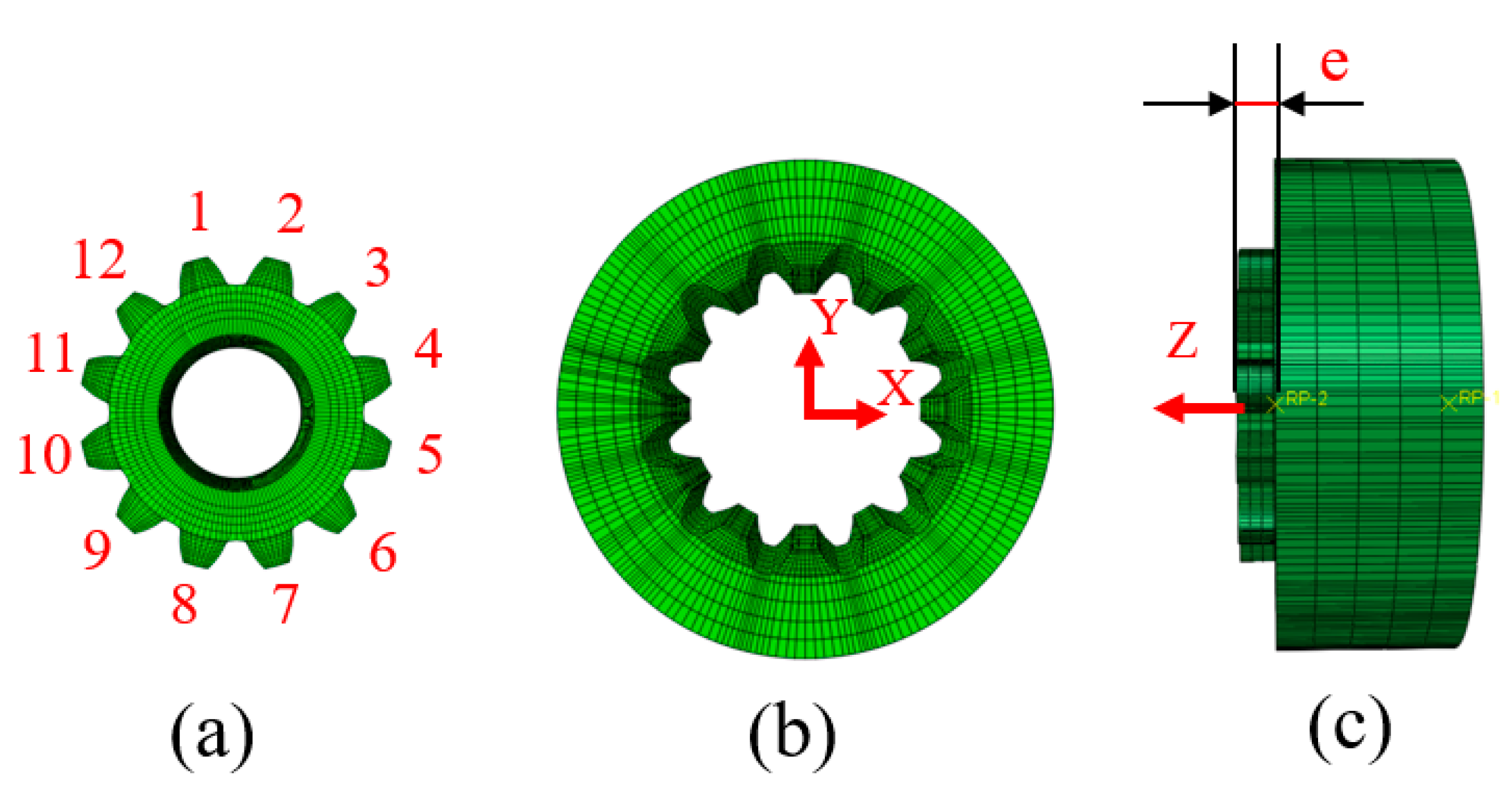
Based on the energy dissipation method and the actual working conditions of the aviation floating involute spline couplings, this article proposed a wear calculation model for the aviation floating involute spline couplings with axial floating distance. The distribution law of tooth surface wear of involute spline couplings before and after carburizing treatment was investigated. The axial floating distances were set to be 0 mm, 0.3 mm, and 0.6 mm, respectively. The contact stress and relative slip rate between teeth under these three working conditions were analyzed in Abaqus software, and the distribution law of wear depth of spline tooth surface along the axial and radial direction was studied based on the simulation results. Finally, the simulation results were verified through experiments, it provides a theoretical basis for the design and maintenance of aviation involute spline couplings.
Different from other studies, this study divided one wear cycle of floating involute spline couplings into three wear stages, analyzed the main wear forms of the three wear stages, respectively, and derived the wear depth calculation model suitable for floating involute spline couplings, which provides an important mathematical basis for the subsequent study of floating involute spline to establish a dynamic model. In addition, this paper also carburized the spline couplings, which is relatively rare in the study of spline friction and wear properties, providing a necessary theoretical idea for the aviation manufacturing industry to design and process high-performance and efficient spline couplings.
2. Wear Prediction Model of Floating Spline Couplings
2.1. Wear Mechanism Analysis of Floating Spline in the Working Process
According to the wear theory and process analysis [
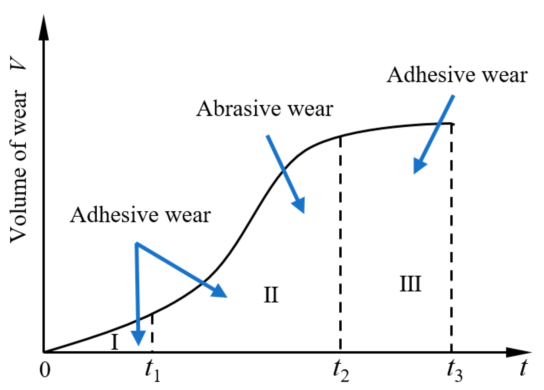
33], because of the actual working process of the floating involute spline couplings, the wear stages are divided into stage I, stage II, and stage III, respectively, corresponding to the low wear stage, the wear conversion stage, and the severe wear stage.
In stage I, when the internal and external splines just started to make contact, with the change in temperature, the lubricating oil in the contact area was forced out, resulting in poor lubrication conditions. In addition, there was a floating distance at the end of the transmission shaft, which caused the internal and external splines to have a sliding distance. At this stage, the spline wear was mainly adhesive, accompanied by slight abrasive wear.
In stage II, due to the continuous accumulation of wear particles on the spline contact surface in stage I and the increase in temperature after working for a while, the adhesion effect between metals occurs, and the adhesion node formed by this effect shears and breaks with the relative sliding of the friction pair surface, resulting in a large amount of adhesive wear on the surface and subsurface of the motion pair and metal migration and the separation of metal particles. These separated metal particles act as wear particles, promoting and accelerating the appearance of more furrows on the spline couplings contact surface at this stage, so the wear of wear particles is aggravated. Therefore, at this stage, the spline wear is mainly (collectively called) abrasive wear and adhesive wear.
In stage III, with the increase in the spline working time and wear in stages I and II, the working stability of spline couplings and the performance of the tooth surface decrease significantly. With the increase in the floating distance, the wear of the tooth surface becomes more serious. At this time, the worn form of the tooth surface is mainly adhesive wear with oxidation wear.
To sum up, the analysis of the wear stage of the floating involute spline couplings is shown in
Figure 1, where
is the wear of stage I, and the main wear form is adhesive wear;
is the wear of stage II, and the main wear forms are adhesive wear and abrasive wear; and
is the wear of stage III, and the main wear form is adhesive wear.
2.2. Calculation Model of Wear Depth of Floating Involute Spline
In the existing research on the calculation of tooth surface wear of floating involute spline couplings, the Archard wear equation is usually used, and the Archard model is often applied to the case of large relative slips between contact planes. However, due to the existence of the axial floating distance, the meshing degree of the tooth surface of the internal and external spline couplings is also constantly changing. The Archard model cannot accurately analyze the surface contact under this condition and cannot accurately calculate the adhesive wear and abrasive wear between the internal and external splines of the floating involute. The energy dissipation method is based on the relationship between the wear amount and the energy loss in the wear process, which is more suitable for the wear process of floating involute spline couplings.
In the energy dissipation equation, it is assumed that the relationship between the wear amount and the energy lost in the friction process is linear. The relationship between the wear volume
and the dissipated energy
in a cycle is:
Among them,
is the energy wear coefficient of the interaction studied under a given sliding amplitude, which can be deduced from the Coulomb formula as
,
is the friction coefficient of the contact surface,
is pressure coefficient on the contact surface of spline couplings and
is the total number of cycles included in the spline couplings wear process. The relationship between the auxiliary loss volume
of the floating involute spline is shown in Equation (2).
where 1 is the wear amount of stage I in the wear life cycle of spline couplings; 2 is the wear amount of stage II in the wear life cycle of spline couplings; and 3 is the wear amount of stage III in the wear life cycle of spline couplings.
In stage I, the worn form is mainly adhesive wear. Based on the energy dissipation method, set the sliding distance increment of
and take differential transformation for a linear contact area with a small area of
:
where
is the tangential force generated in the process of friction and wear. In the initial wear stage, the tooth surface is relatively flat and
is relatively evenly distributed, so the shear stress at this stage is approximately regarded as a fixed value where the shear stress
is:
where
is the normal wear speed of stage I in the wear life cycle of spline couplings;
is the relative slip rate of the contact area. The time integration on both sides of the equation is as follows:
Therefore, the calculation formula of stage I in the wear calculation model of floating involute spline couplings is as shown in Equation (7).
In stage II, the wear forms are mainly abrasive wear and adhesive wear. According to reference [
33], this paper mainly considers the influence of slip rate and normal load and calculates the wear depth of abrasive wear and adhesive wear in the s stage II, and then calculates the general formula of wear depth in stage II. Since the wear calculation formula of adhesive wear has been derived in stage I, the derivation will not be repeated here. Here, it is only necessary to deduce the formula for calculating the wear depth of stage II and then calculate the formula for calculating the wear depth of stage II.
Define the sliding distance micro increment
;
is the tangential force generated in the process of friction and wear. In stage II, wear particles are produced due to abrasive wear, which leads to flat contact surfaces and different sizes of wear particles. Therefore, the shear stress is regarded as a variable. At this time, the shear stress
is a differential transformation of a linear contact area with a small area of
:
where
is the normal wear speed under abrasive wear in stage II of the spline coupling wear’s life cycle, and
is the relative slip rate of the contact area. The time integration on both sides of the equation is as follows:
That is to say, the calculation of the wear depth of abrasive particles applicable to floating involute spline couplings obtained by the energy dissipation method is shown in Equation (12). In combination with Equation (7) for calculating the adhesive wear depth, the formula for calculating the wear depth of floating involute spline couplings in stage II is shown in Equation (13):
In stage III, the worn form of the spline couplings tooth surface is mainly adhesive wear, and the wear depth at this time is calculated as shown in Equation (14).
In conclusion, the formula for calculating the wear depth of floating involute spline couplings is finally determined as shown in Equations (16) and (17):
where
is the wear time of stage I,
is the wear time of stage II, and
is the wear time of stage III.
4. Wear Analysis of 32Cr3MoVA Involute Spline Tooth Surface without Carburizing Treatment
As an example of splines other than those in this section, the axial and radial wear distribution law of the tooth surface of the spline couplings without carburizing treatment and the wear distribution law of each tooth surface is analyzed, respectively, when the floating distance is 0 mm, 0.3 mm, and 0.6 mm. To further characterize the distribution of the tooth surface in the three wear stages, t1 is selected from stage I of the wear cycle; t2, t3, and t4 are selected from stage II of the wear cycle; and t5 is selected from the III of the wear cycle, and the wear distribution law of the tooth surface at these five times is analyzed (the simulation is only conducted once for each working condition, and the simulation process is unique, so the wear depth value is also non-repeatable).
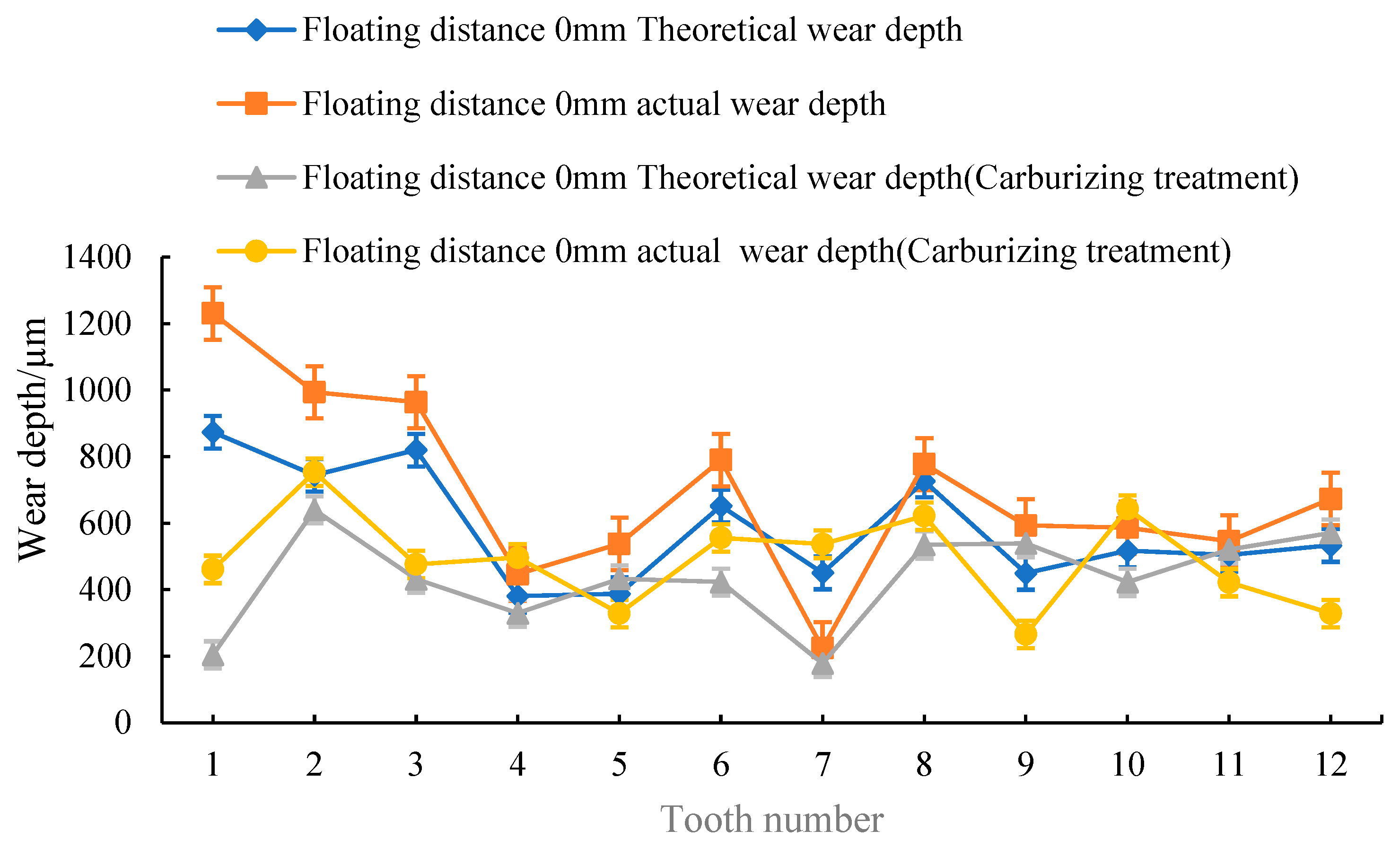
4.1. Floating Distance Is 0 mm
When the floating distance is 0 mm, simulate the actual spline couplings and obtain the distribution curve of the axial and radial wear depth of a tooth surface of the involute spline, as shown in
Figure 3 and
Figure 4. When the floating distance is 0 mm, the tolerance grade of the model is 6, and the backlash is randomly distributed, so there is a certain difference in the distribution of wear depth among the teeth.
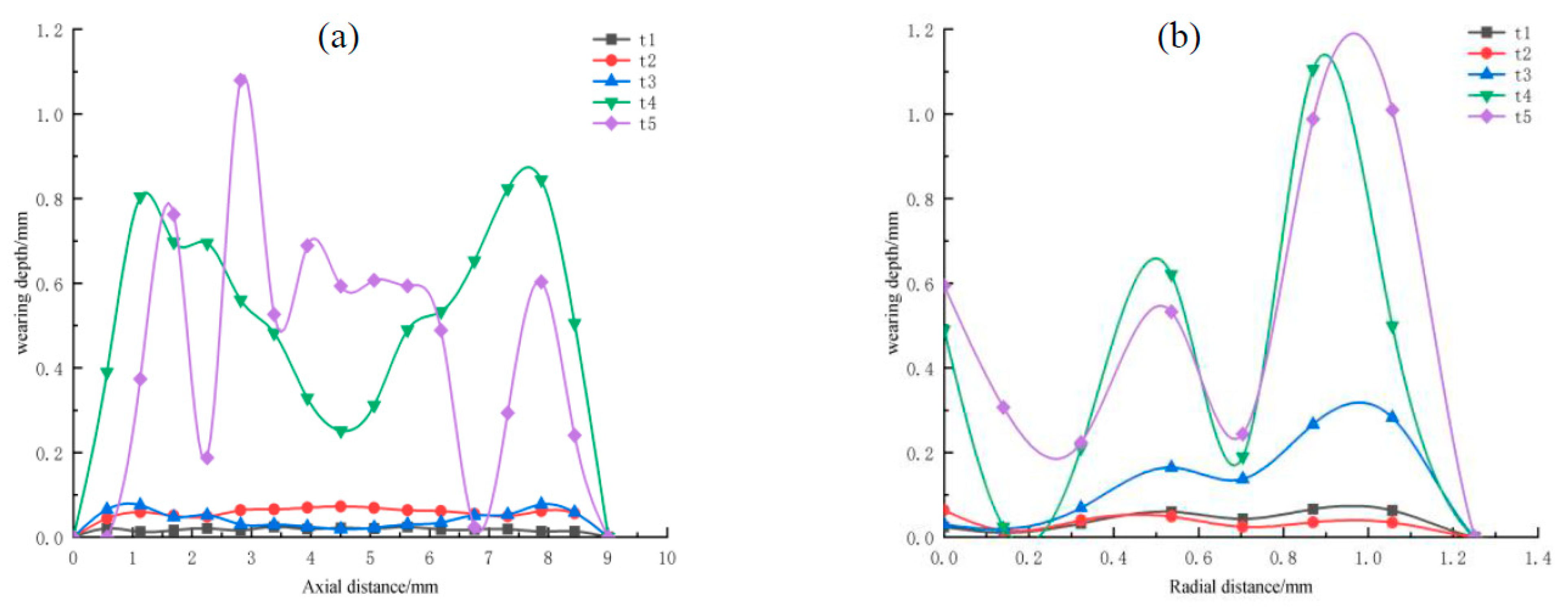
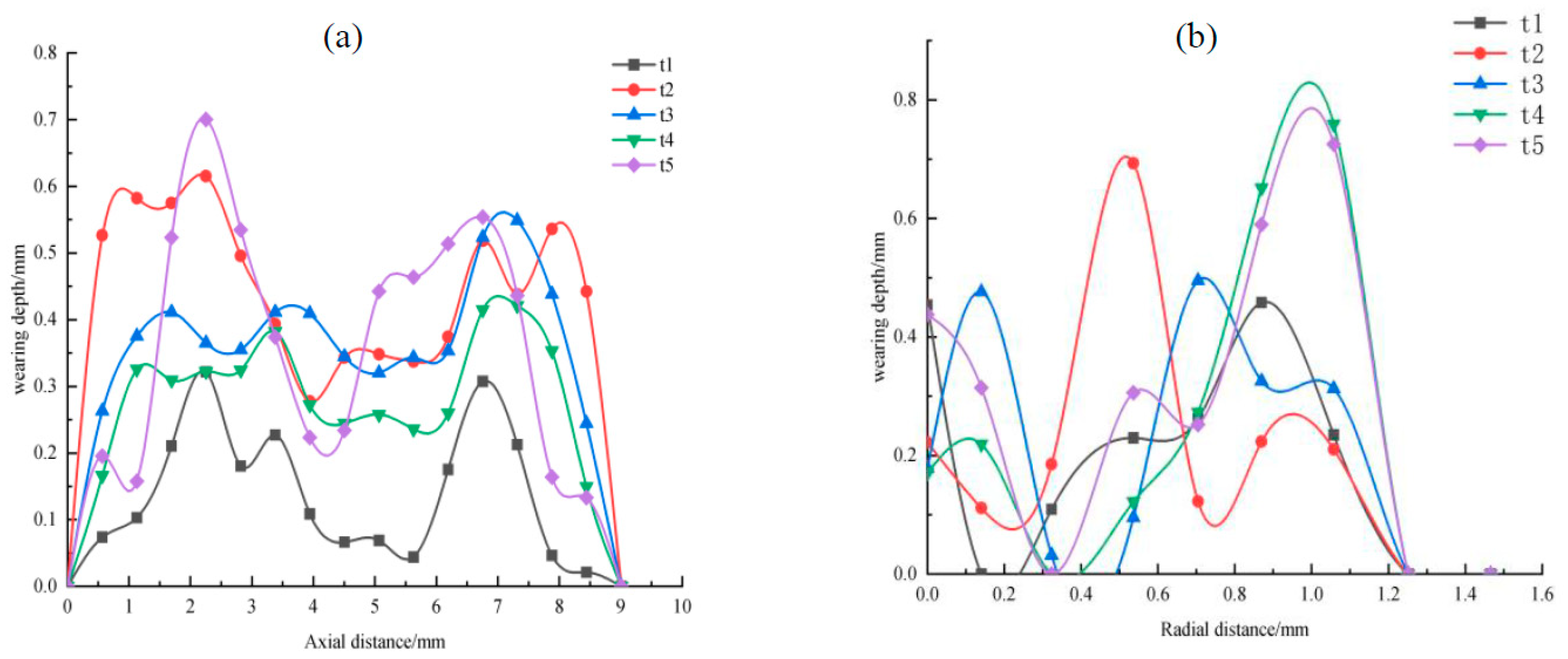
According to
Figure 3a,b, the maximum wear depth is at 1 mm and 8 mm along the axial direction, the minimum is at 2 mm and 7 mm, the maximum is from 0.8 mm to 1.0 mm along the radial direction, and the minimum is at 0.2 mm. Regardless of the axial or radial position, the maximum wear depth is located at both ends of the tooth surface, and the wear depth at the middle part is the smallest. The fretting increases with time, leading to an increase in wear depth. In the figure, the fretting wear degree at t1 and t2 is smaller. This may be because the fretting wear degree is lighter at the initial stage of fretting due to good lubrication and the existence of oxide film. The fretting wear degree at t3 and t4 stages start to increase, which may be due to the extrusion of the lubricating fluid, the rupture of the oxide film, and the generation of a large number of metal particles between the spline couplings contact surfaces. These particles act as abrasive particles after oxidation, which aggravates the fretting wear. The fretting wear degree decreases at the t5 stage; this may be due to the formation of a three-body bed of wear particles generated between the contact surfaces of spline couplings, which plays a role in lubrication and adjustment. Therefore, the fretting wear degree increases.
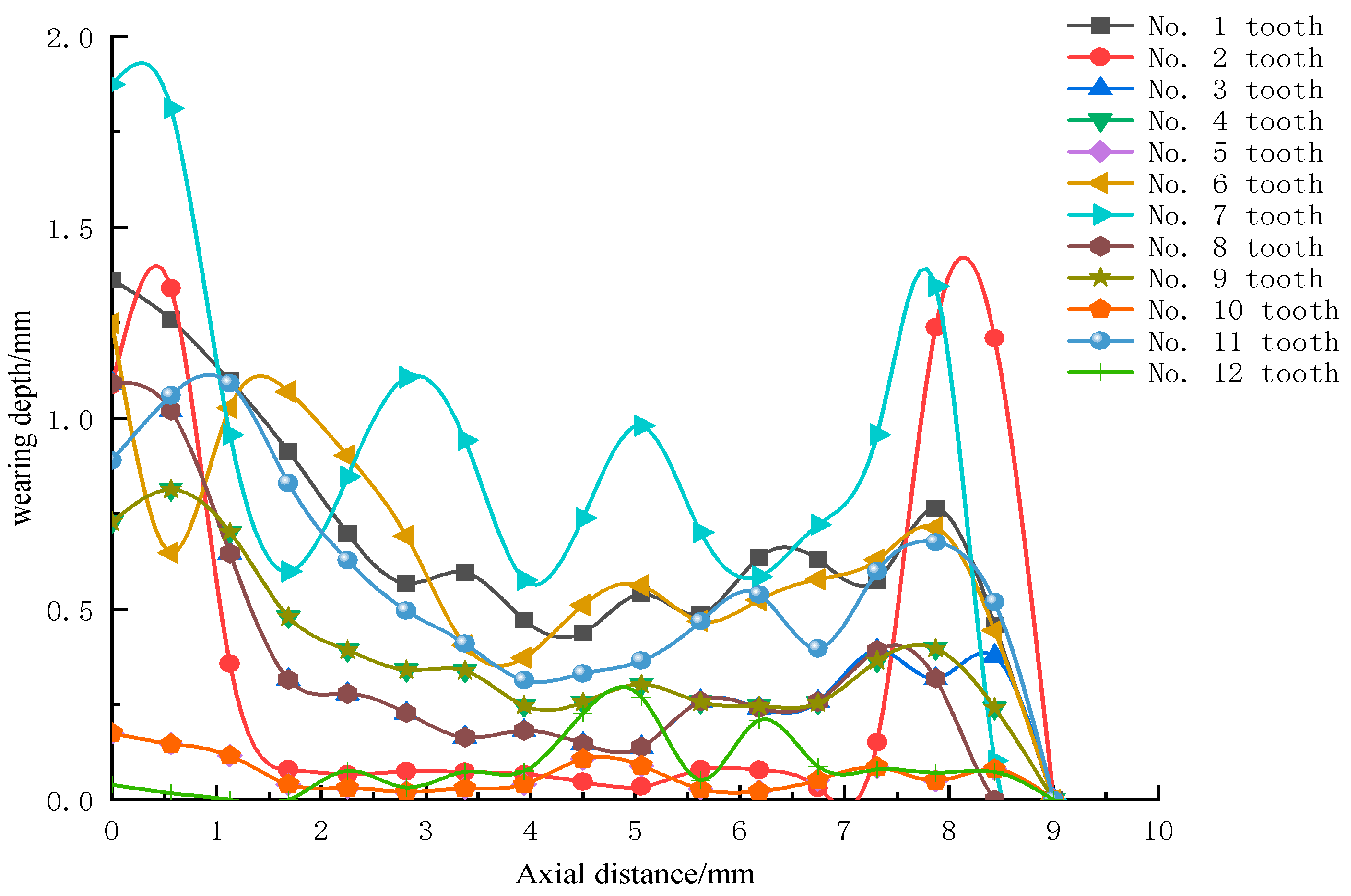
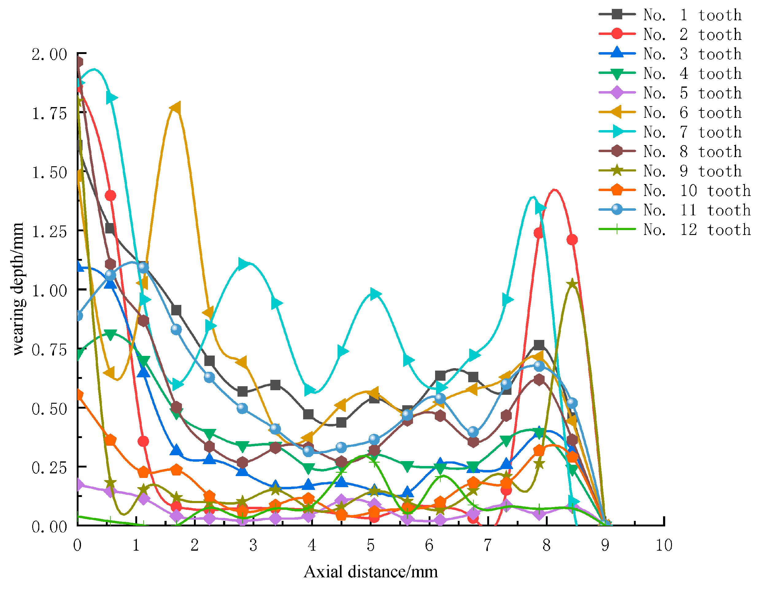
In
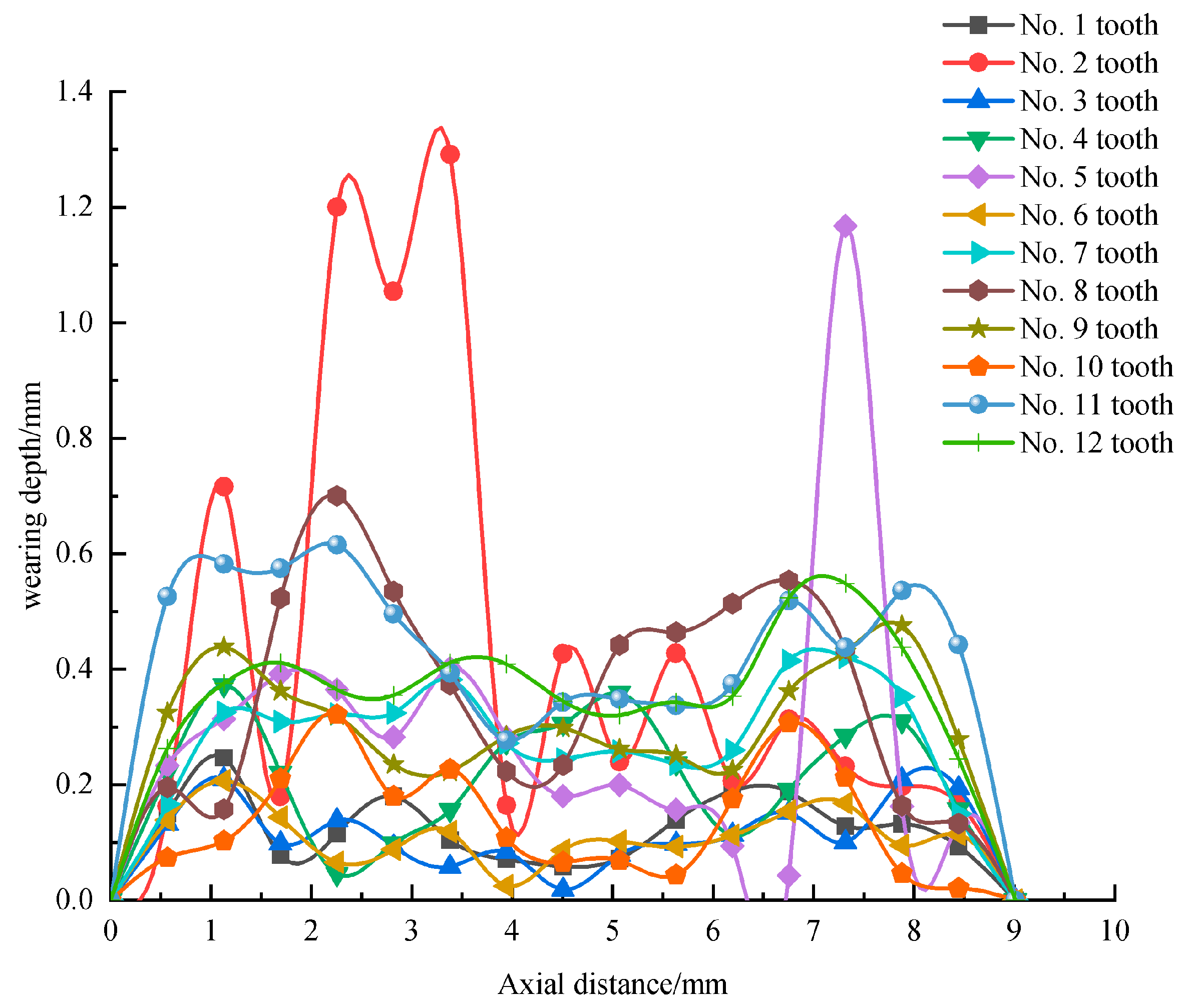
Figure 4, when the axial floating distance is 0 mm, the wear depth of each tooth is different, which may be due to the influence of tooth clearance and mass eccentricity. In addition, the wear of each tooth at 0–2 mm and 8–9 mm at both ends is relatively large. This is because the spline couplings repeatedly make contact with the edge of the tooth when it is just in contact during the working process, resulting in serious wear at the edge of the tooth.
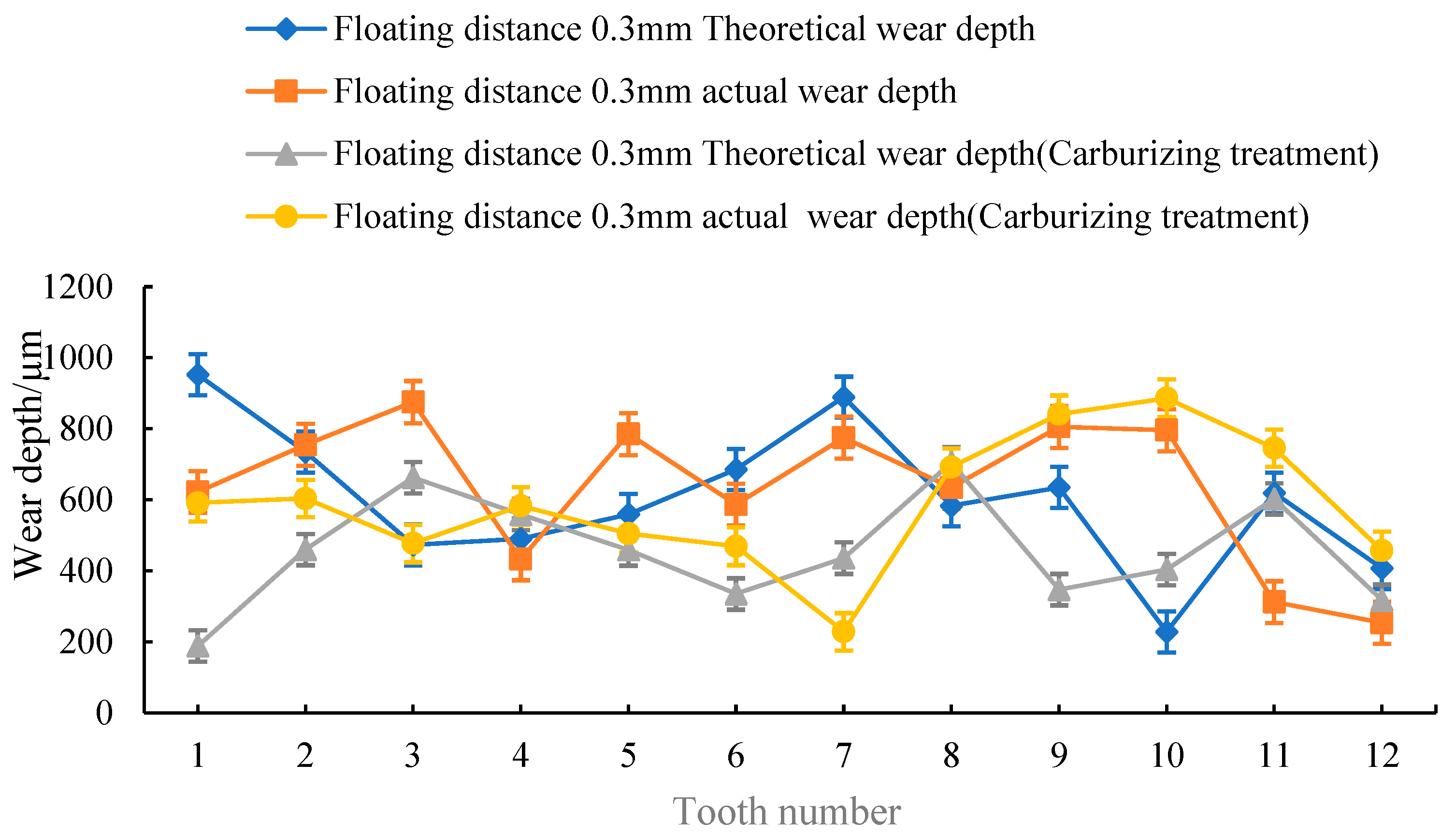
4.2. Floating Distance Is 0.3 mm
When the floating distance is 0.3 mm, the actual spline couplings are simulated, the wear depth of the tooth surface is calculated and analyzed, and the axial and radial wear depth distribution curve of a tooth surface of the involute external spline is obtained, as shown in
Figure 5 and
Figure 6.
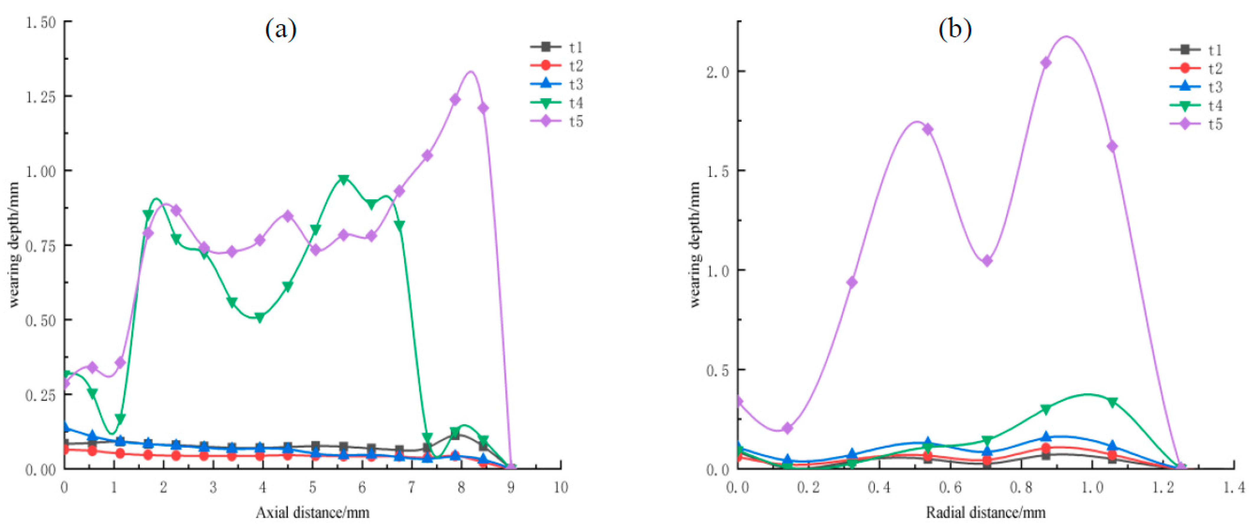
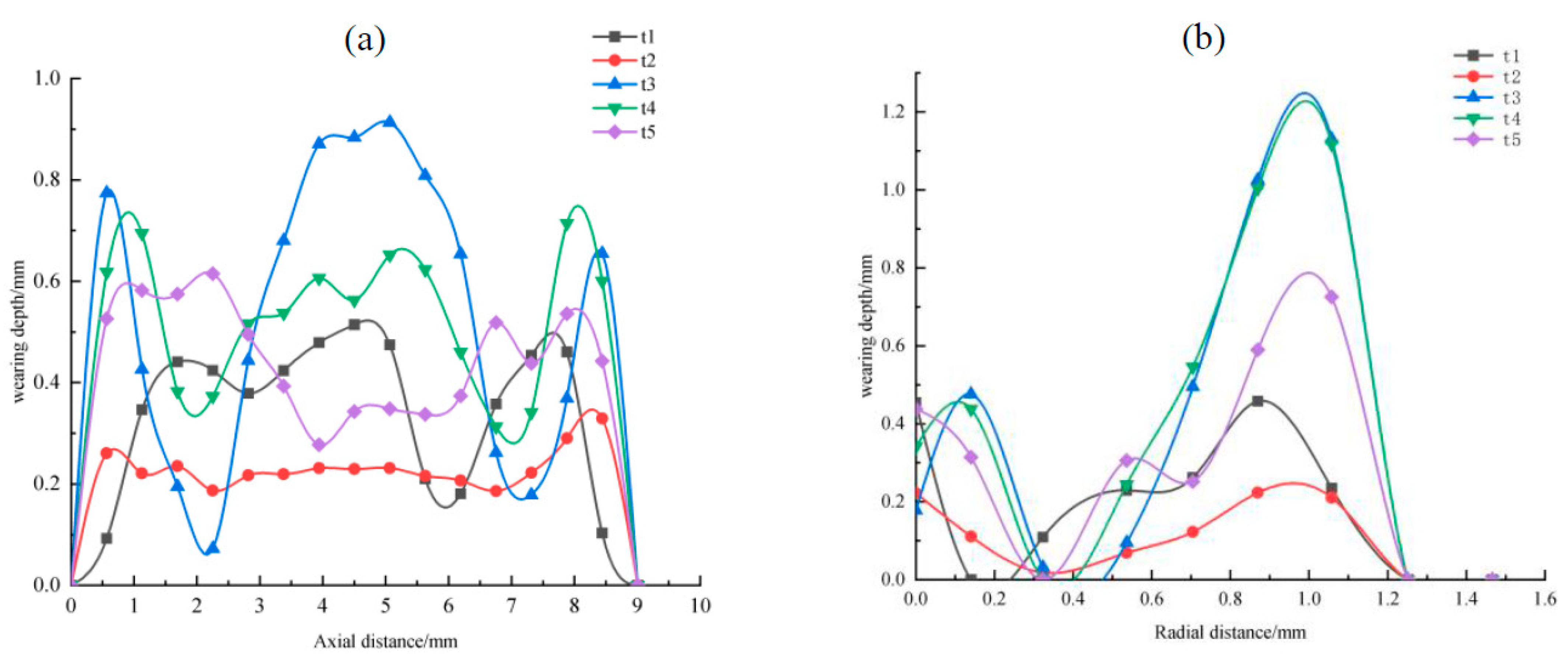
According to the analysis of
Figure 5a,b, the maximum wear depth is at 8 mm along the axial direction, the minimum is at 3 mm to 4 mm, the maximum is at 1.0 mm along the radial direction, and the minimum is from 0 mm to 0.2 mm. Regardless of the axial position or the radial position, the maximum wear depth is located at both ends of the tooth surface, and the middle wear depth is the minimum. The fretting increases with time, resulting in increased wear depth. The fretting wear degree in axial directions t1 and t2 is relatively small, which may be due to the good lubrication effect and the existence of oxide film at the early stage of fretting, so the fretting wear degree is relatively low. The fretting wear degree starts to increase at the t3 and t4 stages in the axial direction, which may be due to the extrusion of lubricating fluid, the rupture of oxide film, and the generation of a large number of metal particles between the contact surfaces of spline couplings. These particles act as abrasive particles after oxidation, which aggravates the fretting wear degree. In the figure, only the fretting wear degree in the radial direction at the t5 stage is significantly increased, which may be due to the sudden increase in fretting wear degree in the later stage of fretting due to the existence of floating amount.
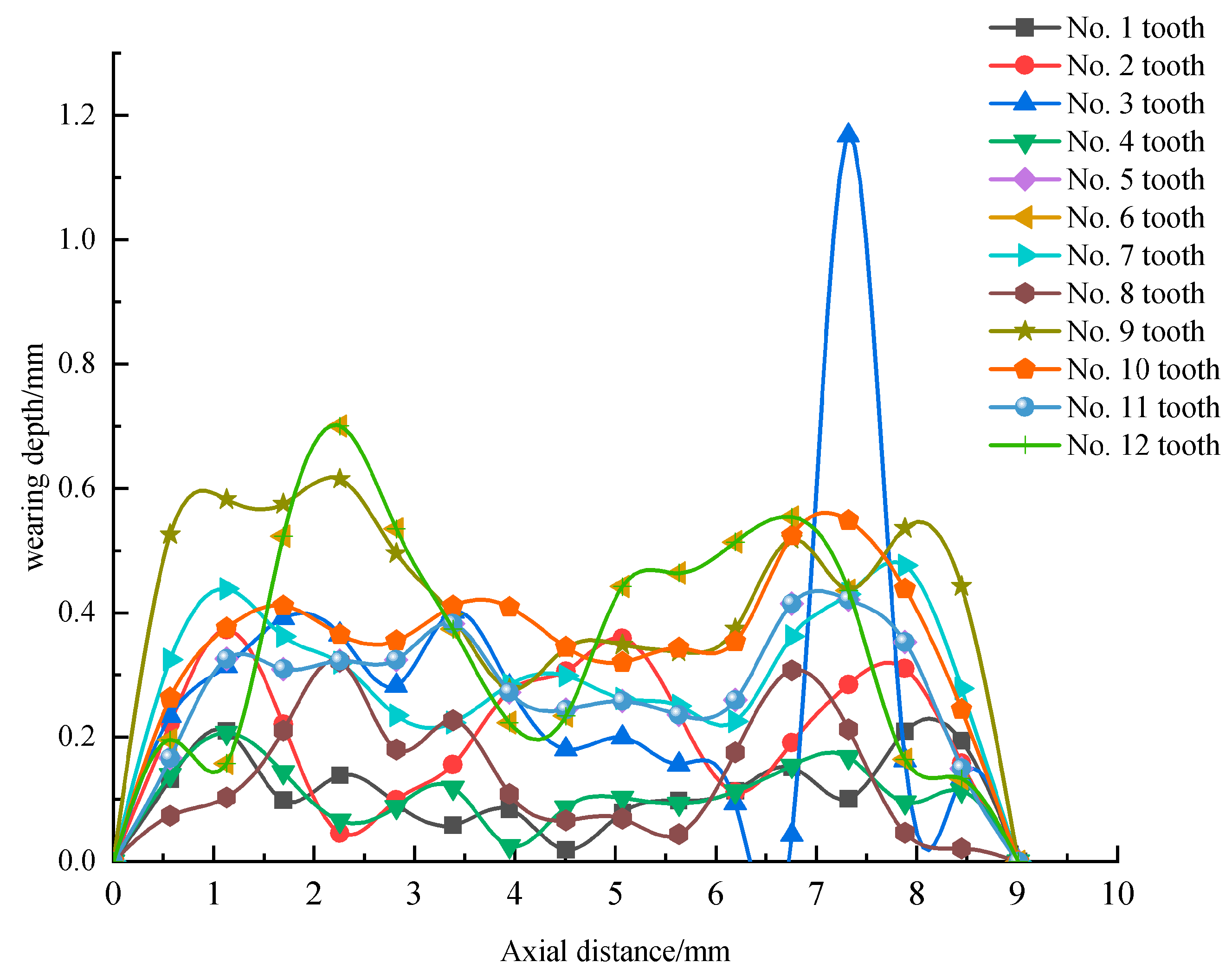
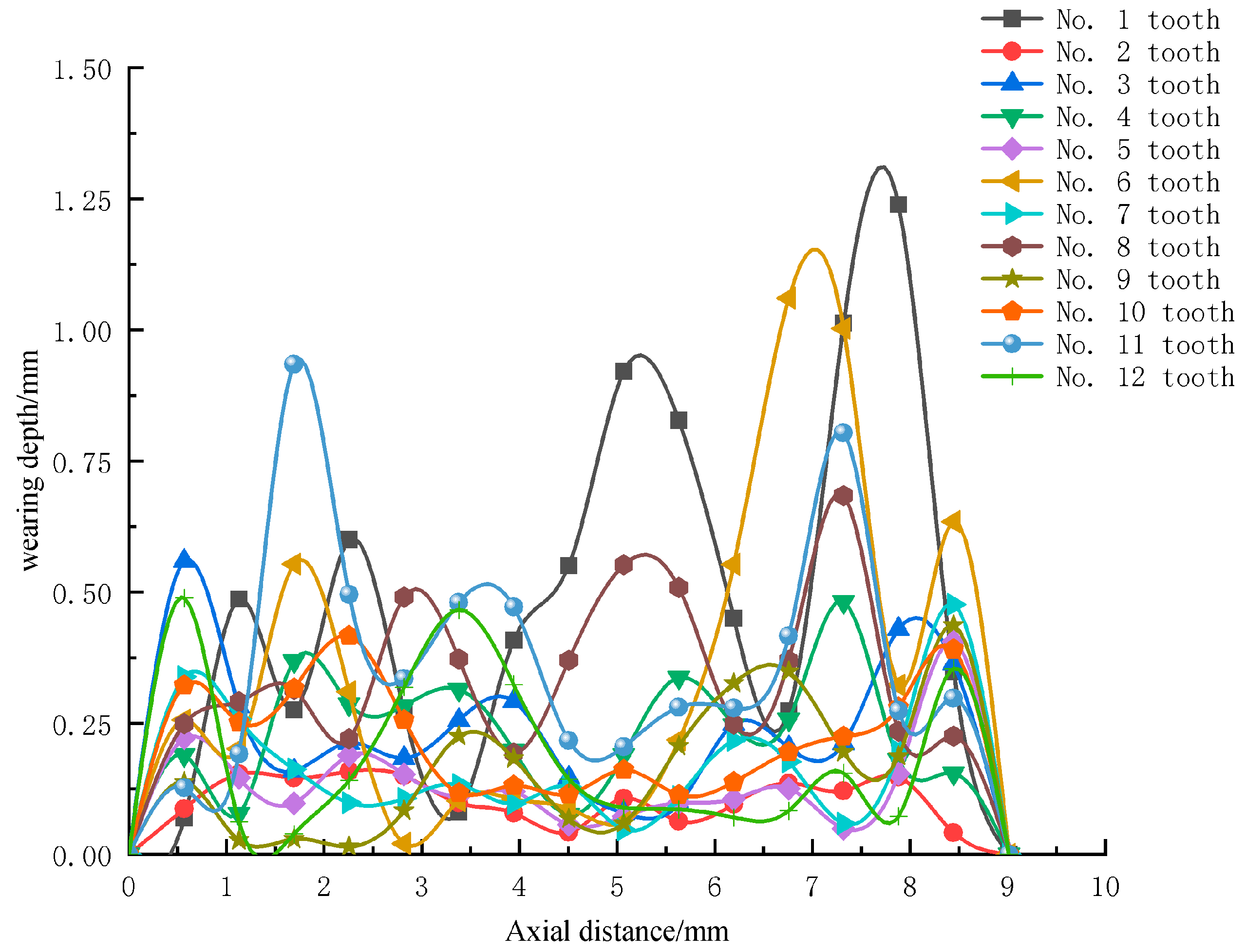
In
Figure 6, it can be found that the wear depth of each tooth is greater due to the increase in floating distance, but the distribution law of wear depth of each tooth still conforms to the fretting wear mechanism of floating aviation involute spline couplings.
4.3. Floating Distance Is 0.6 mm
When the floating distance is 0.6 mm, the actual spline couplings are simulated, and the distribution curve of the axial and radial wear depth of a tooth surface of the involute external spline is obtained, as shown in
Figure 7 and
Figure 8.
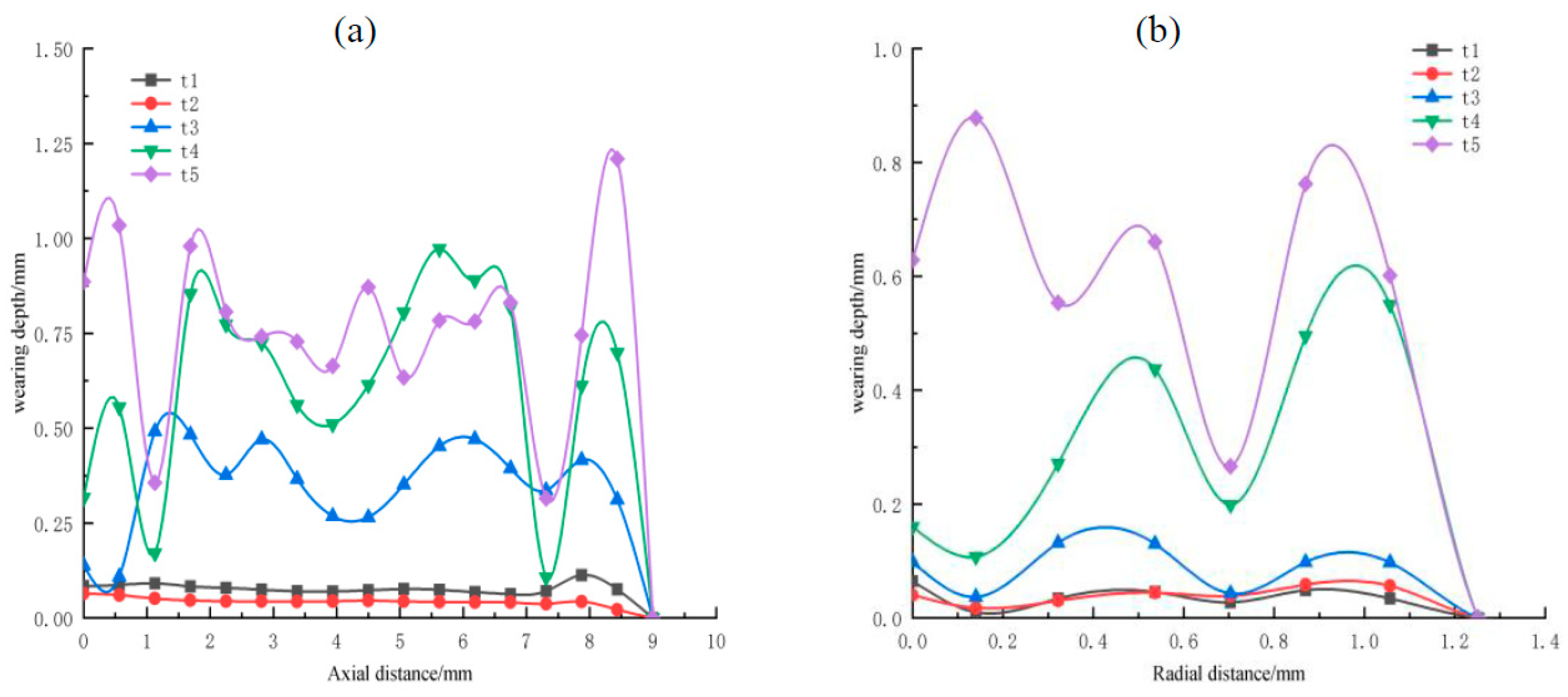
According to the analysis of
Figure 7a,b, the maximum wear depth is at the position of 0 mm–1 mm and 8 mm–9 mm along the axial direction, the minimum wear depth is at the position of 1 mm and 7 mm, the maximum wear depth is at the position of 0.1 mm and 1 mm along the radial direction, and the minimum wear depth is at the position of 0.7 mm. Regardless of the axial position or the radial position, the maximum wear depth is located at both ends of the tooth surface, and the middle wear depth is the minimum. The fretting increases with time, resulting in increased wear depth. In the figure, the fretting wear degree of axial direction t1 and t2 is relatively small, which is similar to that when the floating distance is 0 mm and 0.3 mm. The fretting wear degree in the axial direction t3, t4, and t5 stages in the figure starts to increase, which may be due to the extrusion of lubricating fluid, the rupture of oxide film, and the generation of a large number of metal particles between the spline couplings contact surfaces. These particles act as abrasive particles after oxidation, which aggravates the fretting wear degree. The fretting wear in the radial direction t3, t4, and t5 stages in the figure increases, which may be due to the sudden increase in fretting wear in the later stage of fretting due to the existence of a floating amount. By comparing
Figure 6, it can be found that the wear depth decreases sharply in some areas away from the end of the shaft, which may be caused by the increase in the floating distance. In
Figure 8, it can be found that the wear depth on each tooth is greater due to the increase in the floating distance, but the distribution law of the wear depth of each tooth still conforms to the fretting wear mechanism of the floating aviation involute spline couplings.
4.4. Summary
To sum up, through the analysis of the actual working conditions of the floating involute spline couplings, the influence of the floating distance of the spline couplings is considered when calculating the wear depth using the traditional Archard wear formula, and the finite element simulation software is used to carry out the modal simulation of the spline couplings under three floating distance working conditions. The analysis shows that, with the increase in the floating distance, the wear depth of the tooth surface changes significantly, and the wear depth increases along the floating end. The wear distribution of each tooth under the three working conditions is compared and analyzed. The most serious area of tooth surface wear is mainly distributed on both sides of the tooth; with the increase in floating distance, this distribution becomes more significant.
7. Conclusions
In this work, based on the energy dissipation method, a wear prediction model suitable for the aviation floating involute spline couplings is proposed, and the wear distribution of the aviation floating involute spline couplings before and after carburizing is simulated and analyzed. Finally, the simulation results under the prediction model are verified by experiments. The conclusions are as follows:
(1) Through Abaqus simulation analysis, whether the tooth surface is carburized or not, the wear depth of each tooth of the involute spline couplings will increase with the increase in the floating distance. When the floating distance is 0.3 mm, the wear depth of the tooth surface changes significantly, and the wear depth increases along the floating end, which aggravates the wear of the spline couplings. When the wear depth reaches a certain value, the spline couplings are severely deformed, which cannot meet the use requirements.
(2) Since the fact that the aviation floating involute spline couplings has axial runout, the axial runout speed is coupled with the relative slip rate caused by the contact between teeth, and the wear calculation model applicable to the aviation floating involute spline couplings is reliable.
(3) The most serious wear area of the floating spline couplings is mainly distributed at the edge of the tooth. With the increase in floating distance, this distribution becomes more significant.
(4) When the floating distance is small, by comparing the wear of each tooth surface before and after carburizing treatment, it can be seen that carburizing treatment can improve the performance of the tooth surface, reduce the wear of the tooth surface, and increase the service life of the spline; when the floating distance is too large, the performance of the spline couplings is less affected by carburizing treatment.


