Article

Research on Path Planning and Trajectory Tracking of an Unmanned Electric Shovel Based on Improved APF and Preview Deviation Fuzzy Control

1
School of Mechanical and Aerospace Engineering, Jilin University, Changchun 130022, China
2
State Key Laboratory of Internet of Things for Smart City, Department of Electrical and Computer Engineering, University of Macau, Macao 999078, China
3
Taiyuan Heavy Machinery Group Co., Ltd., Taiyuan 030000, China
*
Authors to whom correspondence should be addressed.
Machines 2022, 10(8), 707; https://doi.org/10.3390/machines10080707
Submission received: 19 May 2022 / Revised: 12 August 2022 / Accepted: 15 August 2022 / Published: 18 August 2022
(This article belongs to the Topic Intelligent Systems and Robotics)

Abstract

:
With the development and upgrading of intelligent mines, research on the unmanned walking of intelligent electric shovels (ES) has been carried out to improve the moving efficiency of extra-large excavators. This paper first introduces an electric shovel’s primary moving condition in an open-pit mine. According to the moving characteristics of the heavy-duty crawler, the artificial potential field (APF) algorithm is improved to plan the moving trajectory of the electric shovel and carry out simulation verification. A dynamic model of an electric shovel is established. A fuzzy control tracking method is proposed based on preview displacement and centroid displacement deviation. The robustness of the tracking algorithm is verified by multi-condition simulation. Finally, the electric shovel prototype is tested through path planning and tracking experiments. The experimental results show that the improved artificial potential field algorithm can plan an obstacle-free path that satisfies the movement of an electric shovel, and the electric shovel can quickly track the preset trajectory. The maximum deviation of the track tracking center of mass is no more than 10 cm, and the deviation of the heading angle when the shovel reaches the endpoint is within 2°.

1. Introduction

Large mining machinery front shovel excavator (ES) refers to an excavator with a single bucket capacity greater than 12 cubic meters, which integrates two functions of excavation and loading in the mining of open-pit solid resources. Taking the WK-55 ES as an example, it is suitable for mining and loading operations in large open-pit mines with a scale of 20 million tons and above [1]. As the annual mining volume of open-pit solid resources globally reaches billions of tons, the demand for large-scale ES will be huge in the future. With the development and upgrading of intelligent mines, it is necessary to research unmanned intelligent ESs to improve operational efficiency and reduce accidents caused by human factors [2,3,4].
By installing a positioning device on an ES, real-time location information can be obtained to realize the path planning and trajectory tracking of the ES. Li designed a perception system for the shovel and tested it on a 1:10 scale shovel experimental platform. Through the combination of real-time kinematic (RTK) and inertial measurement unit (IMU), the system yields information with centimeter-level accuracy [5]. Bijo Sebastian proposed a physics-based autonomous navigation path planning architecture for tracked vehicles that considers slippage and terrain slope. The proposed path planning method consists of a planner and a simulator, and its effectiveness is verified by simulation and experiments [6]. Kim proposed a complete coverage path-planning algorithm that considers earthwork characteristics and environmental constraints. The cost function of the algorithm takes into account the accessibility of the dump truck and the external conditions of the working environment. Furthermore, an evaluation scheme capable of generating quantitative results of path similarity is proposed [7]. Guan proposed a real-time mapping method for terrain traversability estimation and path planning for autonomous excavators in unstructured environments. Learning-based geometric methods incorporate topographic features extracted from RGB images and 3D point clouds into a global map for the planning and navigation of autonomous mining. This method can adapt to changing environments and update terrain information in real-time. Experiments show that excavators can navigate in unstructured environments composed of complex terrain features [8]. Methods based on APF are widely used in the motion planning of mobile robots such as drones and cars [9,10,11,12]. Nazarahari uses the APF algorithm for the path planning of multi-mobile robots in continuous environments. Moreover, the improved genetic algorithm (EGA) is used to find the optimal path between the starting and ending points. The algorithm’s effectiveness for the robot path planning problem is verified by simulation [13]. Fuzzy control algorithms are currently widely used in the tracking control of excavators and other mobile devices [14,15]. Hanh derived the mathematical model of the two-degree-of-freedom electro-hydraulic excavator, and established a trajectory control method based on the fuzzy self-tuning neural network algorithm [16]. Liu proposed a trajectory tracking control strategy for autonomous underwater vehicles based on fuzzy re-planning of locally desired trajectories. The effectiveness of the control strategy is verified by simulation [17]. Zhang proposed a multi-objective trajectory optimization framework based on the pseudospectral method for excavation trajectory planning in autonomous mining scenarios. The effectiveness of the proposed optimal mining trajectory is verified by a large number of simulations and experiments. Compared with other commonly used methods, the proposed framework is more competitive in terms of mining time and energy consumption [18]. An accurate dynamic model of tracked vehicles can improve the performance of control logic in critical driving scenarios. Tota established a nonlinear mathematical vehicle model of an articulated All-terrain tracked vehicle (ATV) in the Matlab/Simulink environment, and analyzed the steady-state lateral behavior of an ATV on flat roads. Aiming at the motion analysis and control of an ATV, an eight-degrees-of-freedom mathematical model of an ATV is established. A linearized vehicle model is proposed to analyze and characterize the steady-state and transient behavior of cornering under slight lateral acceleration. The proportional integral derivative (PID) logic based on torque and speed is proposed, and the angle controller of the hitch is designed and verified [19,20]. Sharma proposed a method of intelligent target recognition for a multi-robot system based on intelligent distance measurement for path planning. This method is based on intelligent distance measurement to find the expected path, which allows a multi-robot system to reach its target following the shortest path without collision [21].
At present, there is little research on path planning and trajectory tracking of large-scale ESs. Due to the complex mining environment and the difficulty of driving heavy mining machinery, the skidding and slipping of the crawler in the moving process can easily lead to an ES being unable to reach the specified position accurately. Therefore, unmanned walking control is the core of realizing the intelligent operation of ESs [22]. The contributions of this paper are as follows:
(1)
Based on the improved APF method and combined with the actual working conditions of the shovel, an obstacle-free path that meets the requirements of the shovel movement is planned;
(2)
Real-time control of ES preview distance and centroid deviation in trajectory tracking based on a fuzzy control method. An ES can quickly adjust the heading angle direction and track the preset trajectory in real-time.
The article is broken down as follows: Section 2 introduces the main movement mode of ES in the open-pit environment; Section 3 studies the path planning and simulation of ES based on the improved APF algorithm; Section 4 proposes a fuzzy control method based on preview distance deviation and centroid distance deviation for ES path tracking; In Section 5, ES trajectory planning and path tracking verification experiments are carried out; Finally, a conclusion is given in Section 6.

2. ES Walking Condition

One of the basic requirements for an ES to accomplish autonomous excavation is to realize autonomous path planning and tracking according to work requirements. The main construction environment of an ES is the open-pit mining area. Since an ES is a heavy mining machine, to improve the safety of its driving, the road is usually leveled in advance with road machinery to avoid danger. Therefore, the obstacles on the road in the mining area are mainly other construction vehicles and stockpiles. The shovel needs to avoid these obstacles to reach the designated position. The principal moving conditions of an ES are shown in Figure 1, which are mainly divided into three operating conditions: straight driving, curved driving, and V-shaped driving:
Condition 1: As shown in Figure 1a, when there are no obstacles on the road, a shovel will choose to walk in a straight line to reach a specific point. In the straight-line condition, there are two situations, forward and backward.
Condition 2: As shown in Figure 1b, when there are rocks and mounds or other construction vehicles on the road, an ES needs to walk in a curve to bypass the obstacles on the road. As with a straight line, there are forward and backward options.
Condition 3: Figure 1c shows the V-shaped displacement trajectory of a shovel. After the excavation of the current location es is completed, an ES needs to be moved to replace the excavation location. Due to the large tonnage of an ES, in situ steering will increase the wear of the tracks and gears and cause the ground to sink. Therefore, an ES needs to first retreat to the middle point and then to the new excavation location. This condition is called a “V” shaped movement.

3. Motion Path Planning Method

3.1. APF Method

The APF method has been maturely applied in mobile robot motion path planning [23,24]. The basic idea of APF is to construct a repulsion field around the obstacle and a gravitational potential field around the target point. As the controlled object, the ES is simultaneously affected by repulsion and gravitational force in the compound field composed of these two potential fields. The combined force of repulsion and gravitational force will control the movement of the ES and search for an unobstructed trajectory on the map. The gravitational potential field is mainly related to the distance between the controlled object and the target point; the greater the distance, the greater the potential energy value of the controlled object; the smaller the distance, the smaller the potential energy value it experiences. The function of the gravitational potential field is shown in Formula (1):
U a t t X = 1 2 η ρ 2 q , q t
Here, η is the proportional gain coefficient, ρ q , q t is a vector, which represents the Euclidean distance q q t between the position of the controlled object q and the position of the target point q t , and the vector direction is from the position of the controlled object to the position of the target point. The gravitational force F a t t X of the corresponding negative gradient of the gravitational field is:
F a t t X = U a t t X = η ρ q , q t
The distance between the controlled object and the obstacle affects the repulsive potential energy of the obstacle. When the controlled object does not move to the influence range of the obstacle, the value of the repulsive potential energy it receives is 0. When the position of the controlled object is within the range of the repulsive potential field of the obstacle, the magnitude of the potential energy it receives is equal to the sum of the two. The distance between them is negatively correlated. The greater the distance between the two, the smaller the repulsive potential energy the controlled object is subjected to. The potential field function in the repulsive potential field is:
U r e p X = 1 2 k 1 ρ q , q o 1 ρ 0 2 0 ρ q , q o ρ 0 0 ρ q , q o ρ 0
Here, k is the proportional coefficient, ρ q , q o is the vector, its value is the distance q q o between the controlled object and the obstacle, the direction is from the obstacle to the controlled object, and ρ 0 is the maximum influence range value of the repulsive potential energy field of the obstacle. The repulsive force F r e q X of the negative gradient of the repulsive force field is:
F r e p X = k 1 ρ q , q t 1 ρ 0 1 ρ 2 q , q t ρ q , q t 0 ρ q , q t ρ 0 0 ρ q , q t ρ 0
The total resultant force F t o t a l received by the controlled object is:
F t o t a l = F a t t X + F r e p X
Figure 2 shows the shortcomings of the APF algorithm that may lead to unreachable targets and local optimal solutions. When the distance between the obstacle and the target point is close, under the action of the resultant force, the gravitational force on the controlled object will be 0. However, the repulsive force is not necessarily 0, which will lead to the problem that the target cannot be reached. Furthermore, under the action of the combined force of multiple obstacles, the combined repulsive force on the controlled object will be equal to the gravitational force of the target point, and opposite in direction, which will cause the controlled object to continue to search for the moving path forward.

3.2. Improved APF Method

The gravitational force will be too large when the ES is too far away from the target point. This can cause the planned path to cross obstacles or the route to be less smooth. As shown in Formula (6), the threshold value ρ d of the influence distance of the gravitational potential field is introduced. When ρ q , q t ρ d , the gravitational force of the target point to ES will increase and decrease, it will be smoother, and it can smoothly avoid obstacles. The gravitational field functions are shown in Equation (6).
U a t t * X = 1 2 η ρ 2 q , q t ρ q , q t ρ d 1 2 η ρ d ρ q , q t ρ q , q t ρ d
The negative gradient derivation of Equation (6).
F = U a t t * ( X ) = g r a d U a t t ( x , y ) = U a t t ( x , y ) = U ' a t t , x ( x , y ) i U ' a t t , y ( x , y ) j = η ( x x t ) i η ( y y t ) j = η [ ( x t x ) i + η ( y t y ) j ] = η ( x x t ) 2 + ( y y t ) 2 = η ρ ( q , q t ) g r a d U a t t ( x , y ) = U a t t ( x , y ) = U ' a t t , x ( x , y ) i U ' a t t , y ( x , y ) j = 1 2 ( η ( x x t ) i + η ( y y t ) j ) = 1 2 η ρ d [ ( x x t ) i + ( y y t ) j ] ρ ( q , q t ) 1 = 1 2 η ρ d [ ( x t x ) i + ( y t y ) j ] ρ ( q , q t ) 1 = 1 2 η ρ d ( x x t ) 2 + ( y y t ) 2 ρ ( q , q t ) 1 = 1 2 η ρ d ρ ( q , q t ) ρ ( q , q t ) 1 = 1 2 η ρ d ρ ( q , q t ) ρ d ρ ( q , q t ) ρ d
The force F a t t * X corresponding to the gravitational function is shown in Formula (8).
F a t t * X = η ρ q , q t ρ q , q t ρ d 1 2 η ρ d ρ q , q t ρ d
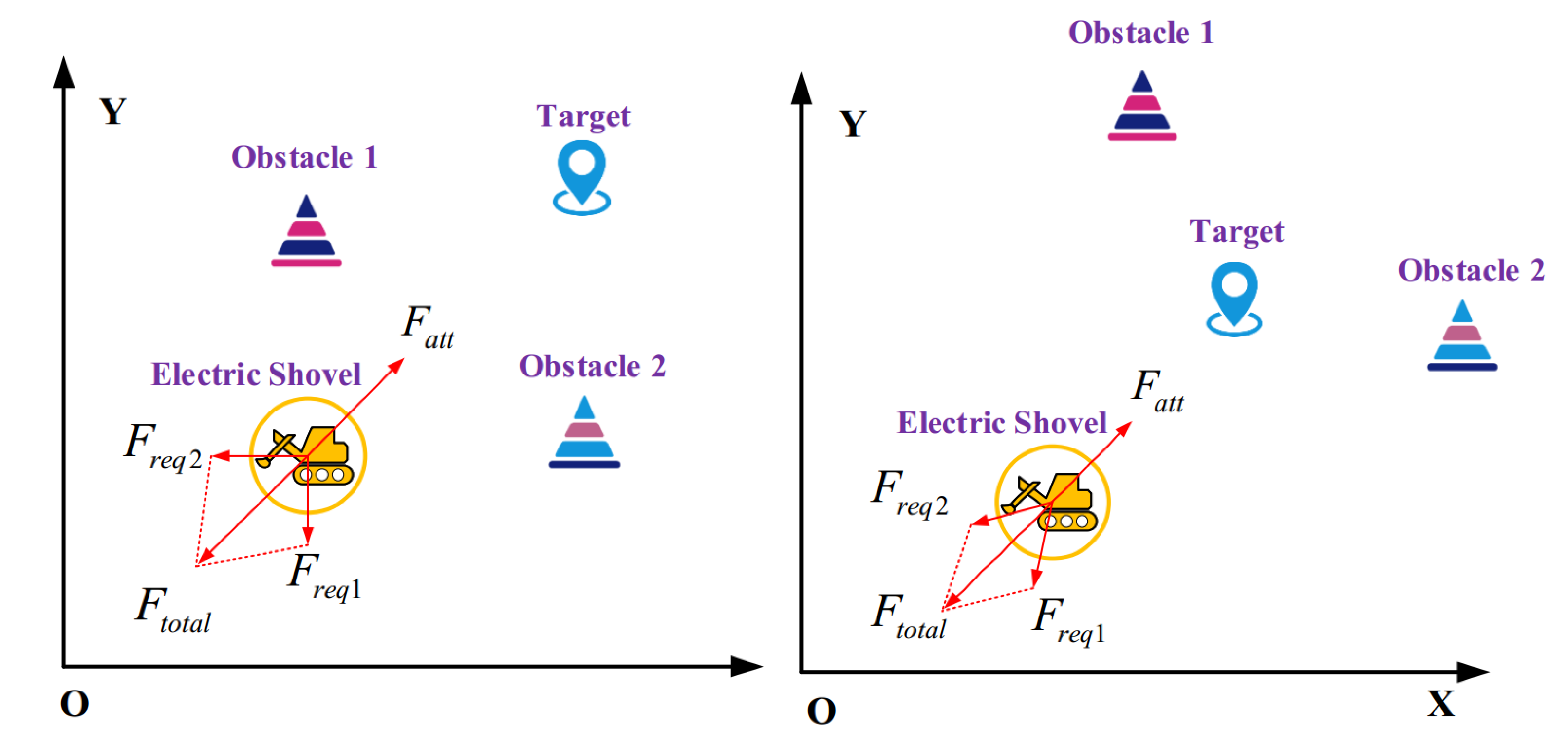
To improve the applicability of the APF algorithm, it is necessary to change the problems of unreachable goals and local optima due to the balance of co-repulsion and gravitational forces. First, a repulsive force adjustment factor ρ n q , q t is added to the repulsive force potential field of the traditional APF. The resultant repulsive force and the attractive force of ES are zero at the same time when it reaches the endpoint. At the same time, the repulsive force F r e q 2 of a part of the obstacles is introduced into the gravitational force of the target point on the ES, which changes the force balance state of the ES during the traveling process. The repulsion function is shown in Formula (9):
U r e p 1 * X = 1 2 k 1 ρ q , q o 1 ρ 0 2 ρ n q , q t 0 ρ q , q o ρ 0 0 ρ q , q o ρ 0
In Formula (9), ρ q , q t is the real-time distance q q t from the obstacle to the target point, and n is a constant. The corresponding repulsive force F r e p o * is shown in Formula (10), where the direction of F r e p 1 * is that the obstacle points to the ES and the direction of F r e p 2 * is that the ES points to the target point:
F r e p o * = F r e p 1 * + F r e p 2 * ρ q , q o 0 ρ q , q o ρ 0 0 ρ q , q o ρ 0
F r e p 1 = k 1 ρ q , q o 1 ρ 0 ρ n q , q t ρ 2 q , q o F r e p 2 = n 2 k 1 ρ q , q o 1 ρ 0 2 ρ n 1 q , q t
In addition, if the ES turns in situ at a large angle during actual work, it will cause the track to sink and make it difficult to turn. According to the heading angle requirement of the final target position of the ES, the concept of a virtual obstacle at the target point is introduced; that is, a new repulsive force field is added to the target point. The newly introduced repulsion potential field has always acted on the ES, and its repulsion direction is always opposite to the heading angle of the final ES. The introduction of a new repulsive potential field can firstly solve the problem of an unreachable target and local optimum. Secondly, it can automatically align the ES when it reaches the endpoint. Its repulsion function is shown in Formula (12):
U r e p 2 * X = 1 2 μ ρ 2 q , q t ρ t q , q t ρ t 1 2 μ ρ d ρ t q , q t ρ t q , q t ρ t
ρ t is the intermediate distance threshold of the target point to the ES repulsion potential field and μ is the proportional coefficient. The repulsive force F r e q 3 corresponding to the repulsive force function is:
F r e p 3 * = U r e p 2 X = μ ρ q , q t ρ q , q t ρ t 1 2 μ ρ d ρ q , q t ρ t
The resultant force field and resultant force experienced by the ES in the improved APF are shown below.
U t o t a l * ( X ) = U a t t * ( X ) + U r e p 1 * ( X ) + U r e p 2 * ( X )
F t o t a l * X = F a t t * X + F r e p o * X + F r e p 3 * X
Figure 3 shows a schematic diagram of the force of the modified APF on the ES. The planned path of the ES will become smooth due to the requirements of the heading angle, and it will face the body when it moves to the final position. The improvement of the gravitational and repulsive potential fields enhances the applicability and planning obstacle avoidance capability of the APF.

3.3. Simulation

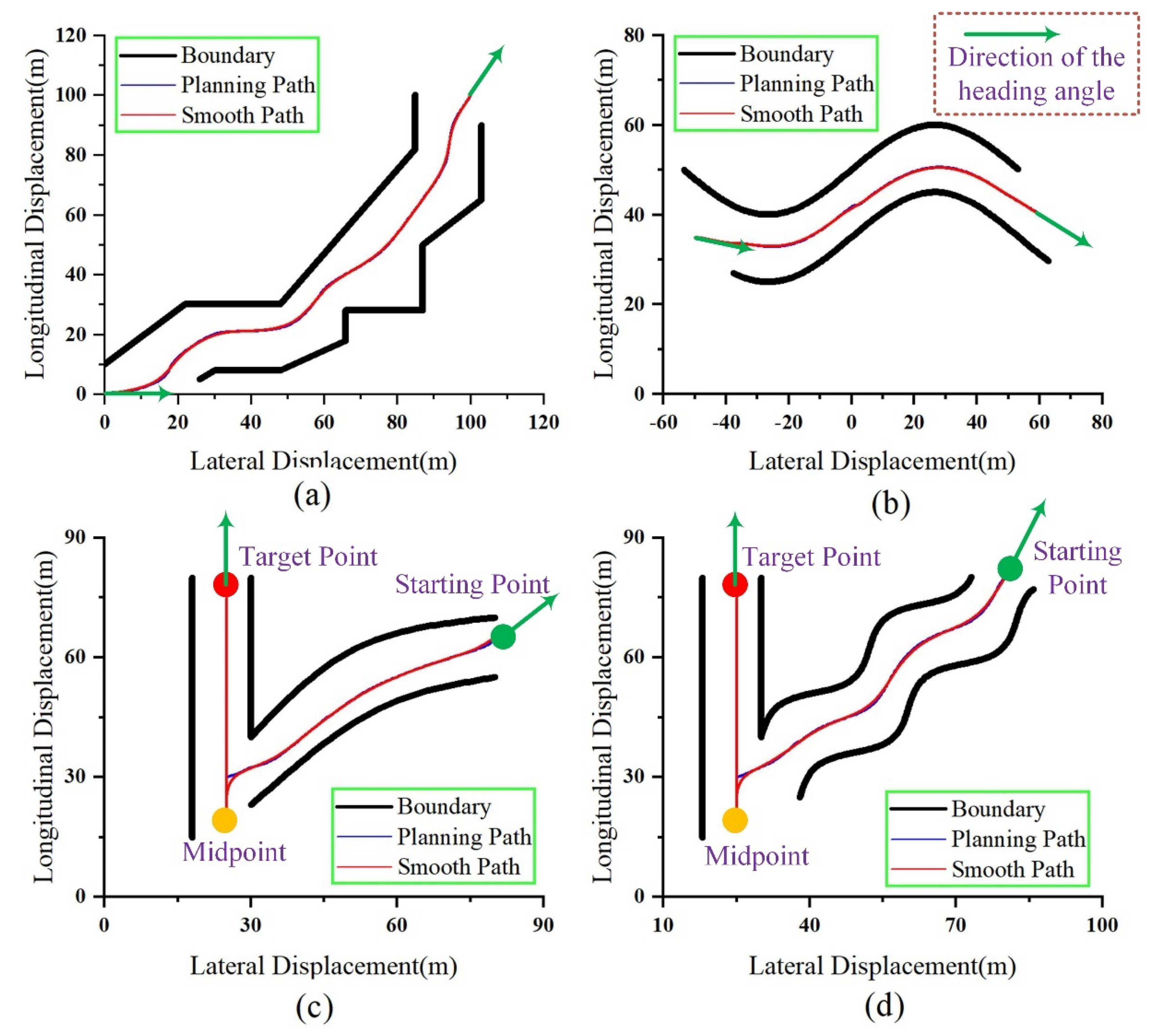
In order to verify the path planning effect of the improved APF, different road shapes are designed according to the three actual driving conditions of the ES. By using the improved APF for path planning, the corresponding results shown in Figure 4a,b are the planned paths with different curved road boundaries, and c and d are V-shaped working conditions. The V-shaped path is essentially composed of two paths, the backward phase from the green point to the orange point, and the forward phase from the orange point to the red point. ES first rewinds from the green starting position to the yellow midpoint and then moves to the red ending position. The large curvature steering problem in the initial planning path will lead to the oscillating behavior of the ES during the movement. In order to make the ES move more smoothly, based on the APF planning, the planned path curve is smoothed based on the cubic B-spline curve. In Figure 4, the blue line is the planned path of the APF, and the red line is the path smoothed by the cubic B-spline curve. The green arrow in Figure 4 indicates the heading angle direction of the ES at the start position and the end position. It can be seen from the simulation results of different working conditions in Figure 4 that the improved APF can better plan the driving trajectory of an ES according to the set obstacles, and the applicable working conditions are more comprehensive.

4. Trajectory Tracking Method

4.1. Kinematics Model of an ES

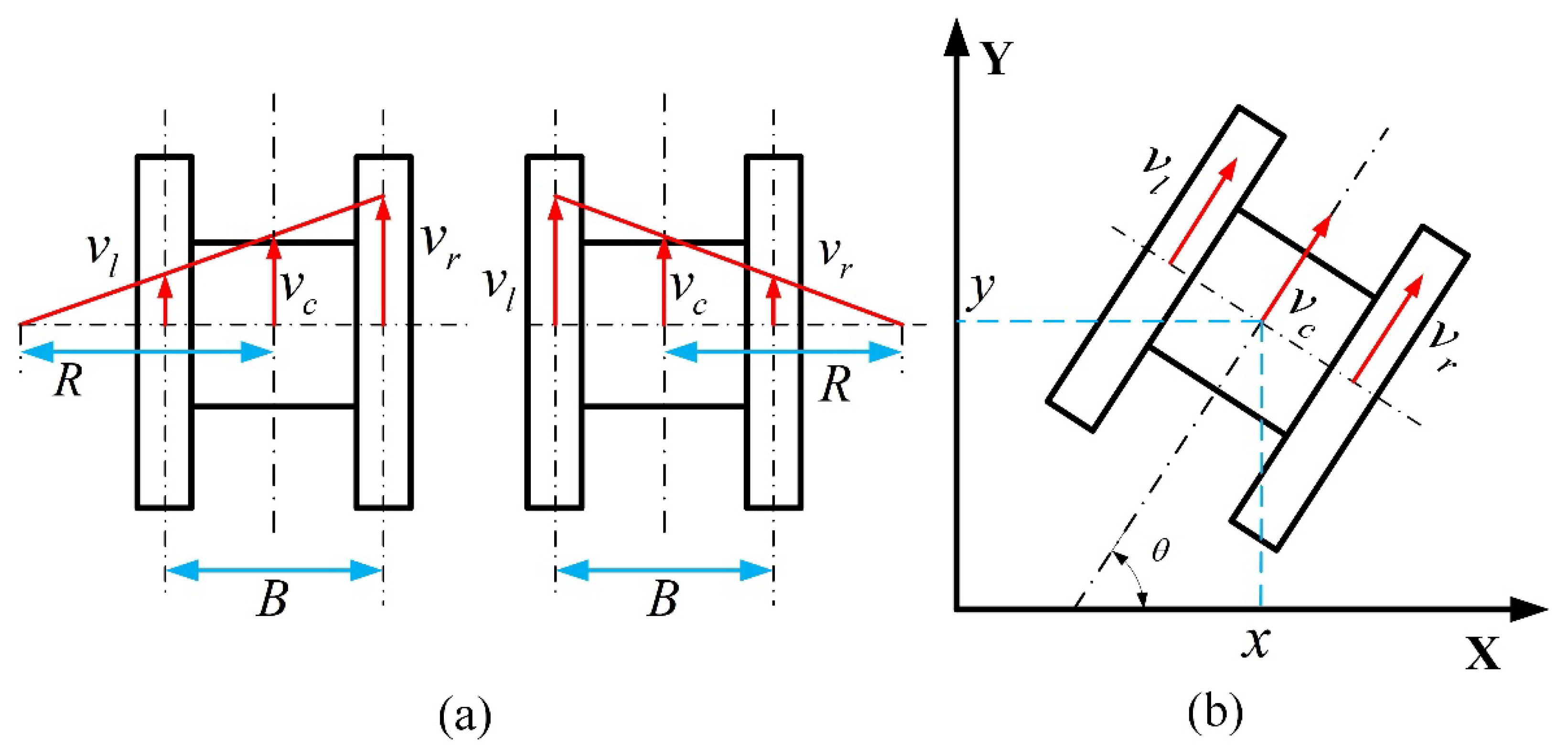
The running mechanism of an ES is a crawler device, as shown in Figure 5a. Assuming that the linear velocity of the center of mass when an ES is moving forward is v c , the turning radius is R, and the distance between the grounding centers of the left and right tracks is B , this distance is conventionally called “track width”, then the track speeds on the left and right sides are v l and v r . The position of the center of mass according to the three-dimensional model of the ES:
v r R ± B / 2 = v l R B / 2
From the above formula, the steering radius and centroid velocity of ES can be obtained as:
R = B ( v r + v l ) 2 v r v l v c = v r + v l 2
Figure 5b shows the plane motion analysis of an ES crawler. The differential equation of motion of an ES center is shown in Equation (18).
x ˙ = v c cos θ = v r + v l 2 cos θ y ˙ = v c sin θ = v r + v l 2 sin θ θ ˙ = v r + v l 2 R
Integrating the above formula can obtain the position coordinates of the center of mass of an ES in the plane coordinate system.
x = x ˙ d t = 1 2 v r + v l cos θ d t y = y ˙ d t = 1 2 v r + v l sin θ d t θ = θ ˙ d t = 1 2 R v r + v l d t
Let x = x , y , θ T be the state vector, u = v l , v r T be the input vector, the matrix state equation of Equation (18) is shown in Equation (20):
x ˙ y ˙ θ ˙ = 1 2 cos θ 1 2 cos θ 1 2 sin θ 1 2 sin θ 1 2 R 1 2 R v r v l

4.2. Trajectory Tracking Strategy

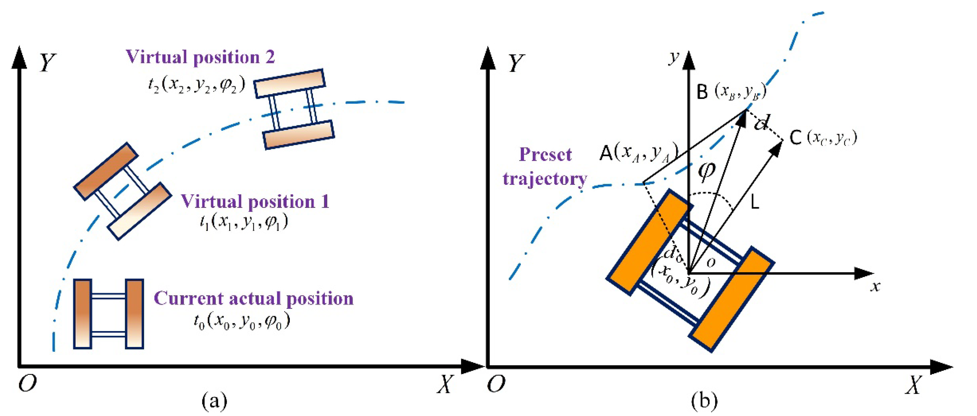
During the operation of an ES, due to factors such as track slippage and slippage, the actual driving route will be far from the initial set trajectory, which will affect the working process and efficiency of the operation. ES trajectory tracking means that an actual ES travels according to the desired trajectory set in advance and accurately reaches the specified position. The vehicle’s heading also needs to be consistent. Figure 6a shows a schematic diagram of ES trajectory tracking. There are two virtual ES positions at different times on the preset trajectory. The actual track is at the position and attitude at the t 0 time. To complete the trajectory tracking task, the ES needs to reach the virtual position the next t 1 time, and the heading angle should also be consistent.
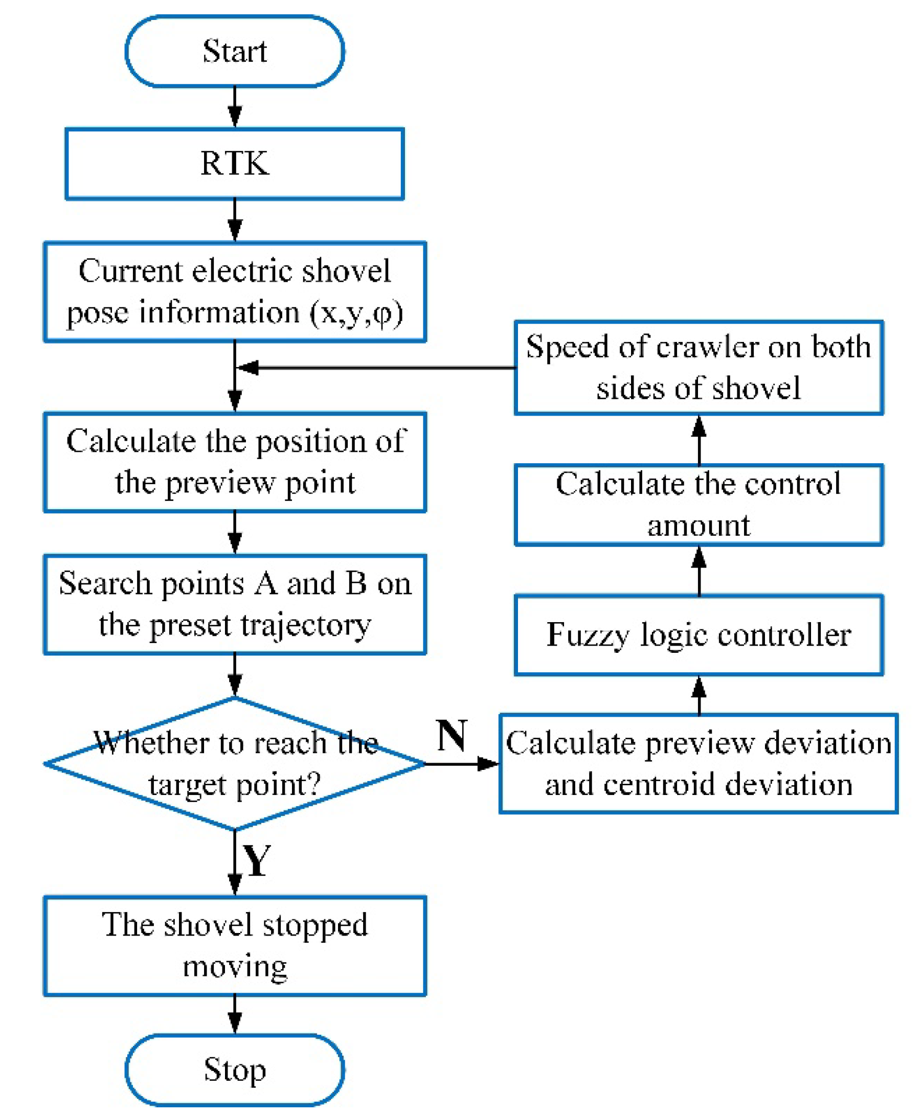
The pose of the ES can be monitored in real-time through RTK technology. By calculating the deviation from the preset trajectory, the speed of the tracks on both sides of the ES can be adjusted actively so that the ES can keep the pose of the virtual target point on the preset trajectory at the next moment. Figure 6b shows the preview deviation and centroid deviation during ES trajectory tracking. The point o is the position of the center of mass of the ES, φ and is the heading angle of the ES. The centroid position coordinates and heading angle information of the ES are collected in real-time through RTK as x 0 , y 0 , φ . The preview point C is a point at a distance L in front of the center of mass of the ES, and the preview distance L is flexibly adjusted according to the traveling speed of the ES. Therefore, the coordinates of the preview point C can be obtained:
x C = x 0 + L sin φ y C = y 0 + L cos φ
A and B are the points searched on the preset track, and the coordinates are ( x A , y A ) and ( x B , y B ) , respectively. Among them, point A is the closest point on the preset track to the centroid o of the current position, and point B is the closest point on the preset track to the preview point. Meanwhile, d 0 is the centroid distance deviation, that is, the distance between the ES centroid point and point A; d is the preview distance deviation, that is, the distance between the preview point in front of ES and point B. Thus, the preview distance deviation and centroid distance deviation of the ES at the current position can be calculated as:
d = ( y B y A ) ( x C x A ) x B x A ( y C y A ) ( y B y A ) 2 + x B x A 2 d 0 = ( y 0 y A ) 2 + x 0 x A 2
It can be seen from the above formula that if the heading angle direction of the actual position of the ES is inconsistent with the forward direction of the preset path, the preview distance deviation of the ES will always exist. The deviation of the preview distance will make the ES track speed adjust until the ES position coordinates and heading angle are consistent with the preset track. Figure 7 shows the flow of the ES tracking method.

4.3. Fuzzy Logic Controller

The ES adjusts the speed of the tracks on both sides according to the preview deviation d and the centroid deviation d 0 to achieve the purpose of trajectory tracking. The two inputs of the fuzzy controller are the lateral displacement deviation e ( t ) and the deviation change rate e c ( t ) , respectively, and the output is the speed difference u ( t ) between the left and right sides of the ES. The lateral displacement deviation e ( t ) is related to the preview deviation and the centroid deviation, calculated by the Formula (23).
e ( t ) = d ( t ) + α d 0 ( t )
In the above formula, α is a positive gain coefficient, and its value is related to the curvature of the trajectory. In the two inputs, the actual universe of the lateral distance deviation e ( t ) in the tracking process is n 1 , n 1 , the actual universe of the error rate of change e c ( t ) is n 2 , n 2 , and the actual speed difference of the output is n 3 , n 3 . The universes used in the variable universe fuzzy control are σ 1 , σ 1 , σ 2 , σ 2 , and σ 3 , σ 3 , respectively. The scaling factor of the lateral displacement deviation domain is k 1 . The scaling factor of the deviation rate universe is k 2 . The scaling factor of the velocity difference universe is k 3 . The variable universe is obtained by multiplying the actual universe and the scaling factor:
σ 1 = n 1 k 1 σ 2 = n 2 k 2 σ 3 = n 3 k 3
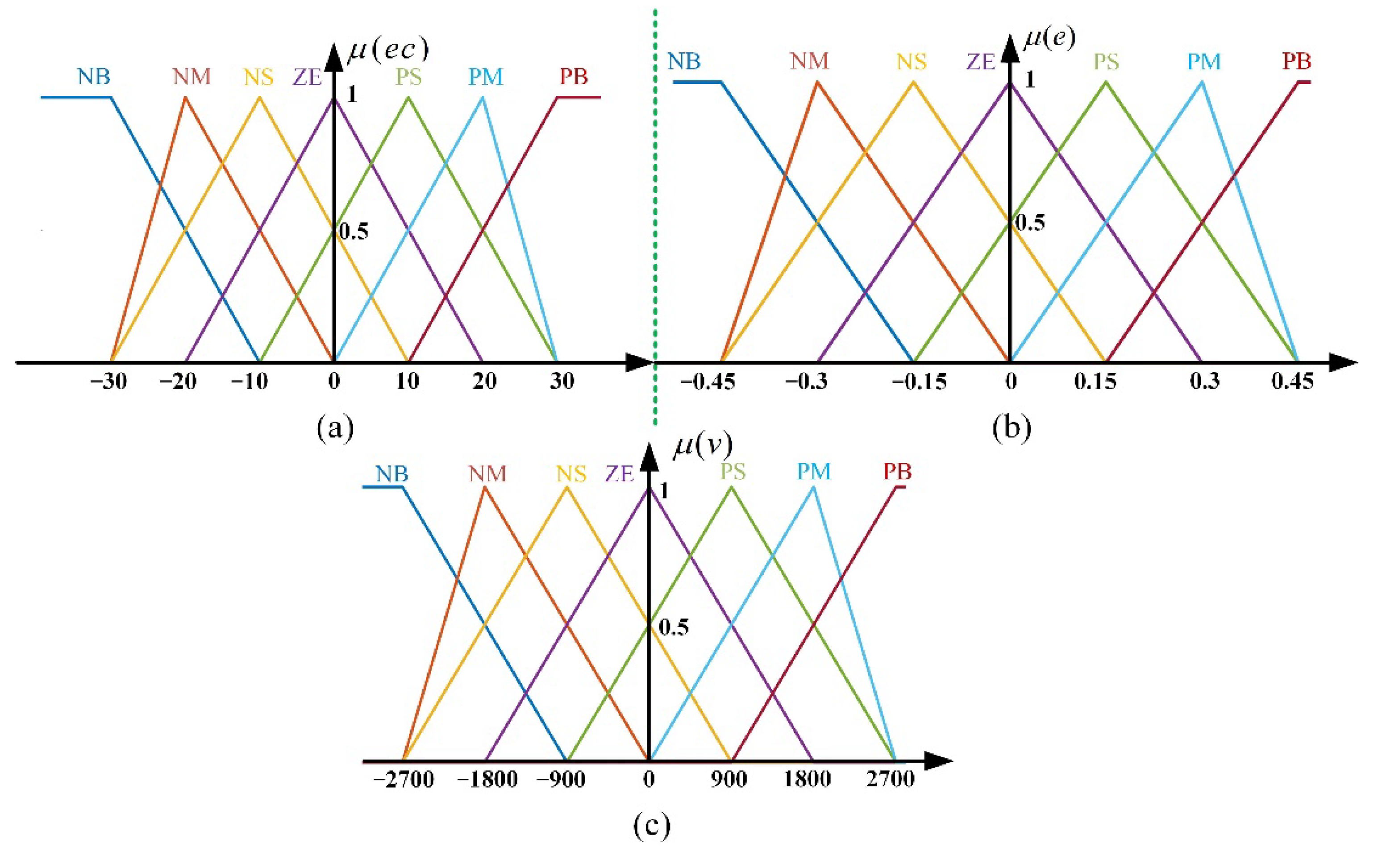
The number of fuzzy subsets is determined according to the requirements of the fuzzy logic control system. Too many subsets will reduce the control precision, while too few subsets will increase the computational burden. Therefore, the number of subsets of the two inputs, lateral displacement deviation e ( t ) and deviation rate of change e c ( t ) is set to N B , N M , N S , Z E , P S , P M , P B . The membership functions for lateral displacement bias e ( t ) and rate of bias change e c ( t ) were chosen as trigonometric functions, considering the feasibility of each fuzzy subset and its accuracy in fuzzy computations. The fuzzy range for the rate of change of deviation is [ 30 , 30 ] . The ambiguous domain range of lateral displacement deviation is [ 0.45 , 0.45 ] . The output velocity difference fuzzy domain range is [ 2700 , 2700 ] , which corresponds to the speed of the motors on both sides of the track. The membership function distributions of the three are shown in Figure 8. The fuzzy control rules are shown in Table 1.
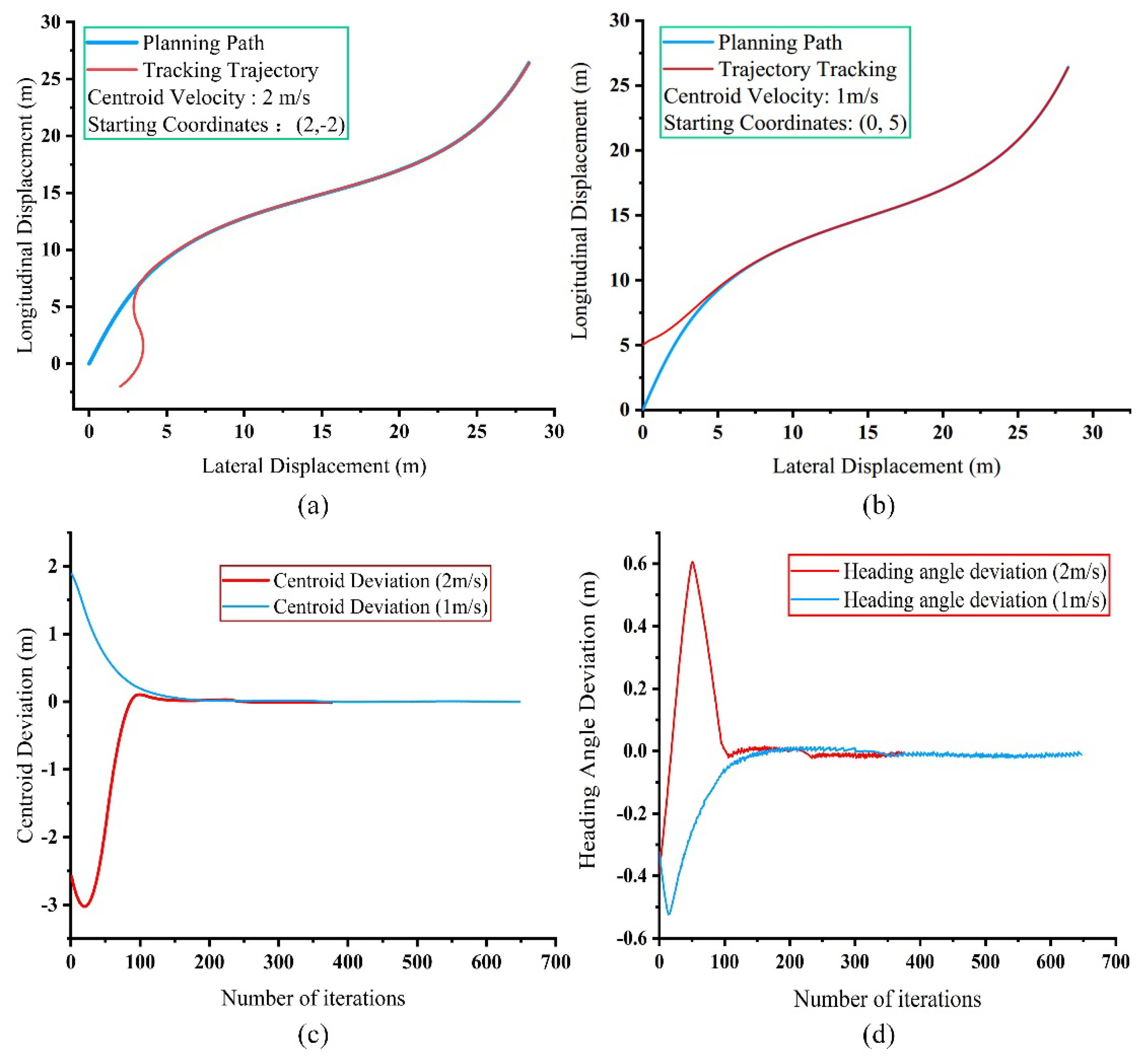
Figure 9 shows the ES fuzzy control tracking simulation based on preview deviation and centroid deviation. The initial position of the planned path is (0,0), and the end position is at (30, 30). The initial heading angle of the ES simulation is π / 4 . In Figure 9a, the initial position of ES is set as (2, −2), and the velocity of the center of mass is 2 m/s. The initial position of ES in Figure 9b is (0, 5). The starting point is above the planned path, and the centroid velocity is 1 m/s. Figure 9c,d show the variation trends of the centroid deviation, and the heading angle deviation with the iteration of the ES calculation path point during the simulation of the two working conditions, respectively. As can be seen from the figure, the ES can quickly track the planned path under both conditions. From the changes of centroid deviation and heading angle deviation, it can be seen that the fuzzy control tracking effect based on preview deviation and centroid deviation is better. Under the speed of different working conditions, the ES can respond quickly, and can track the preset trajectory within 5 m—and the centroid deviation and heading angle tend to 0.

5. Experiment and Discussion

In order to verify the applicability and effectiveness of the ES unmanned walking scheme proposed, based on the actual motion planning of an ES in a mining area, prototype experiments were carried out for different walking conditions, and the experimental results were analyzed and discussed.

5.1. Experimental Setup

The weight of the WK-55 model ES put into production is 1460 t, the bucket capacity is about 55 m3, the height of the whole machine is 22 m, and the crawler is as high as 2 m. In order to facilitate the experimental test, the experiment was carried out on the prototype of the WK-55 model ES which was scaled down at a ratio of 1:7, as shown in Figure 10. The prototype comprises a working device, electrical system, cab, and crawler traveling mechanism. The lower body of the experimental prototype is a crawler chassis, and the upper car is connected to the crawler chassis through a circular slewing bearing platform. The external 380 V AC motor can realize crawler walking, turning on the vehicle, bucket lifting and propulsion, and other actions. RTK equipment is installed above the prototype, including orientation equipment and positioning equipment, which is used to collect real-time pose information of the ES, including spatial position coordinates x , y , z and heading angle φ . RTK carrier phase differential technology is a differential method for the real-time processing of carrier phase observations of two measuring stations. The three-dimensional lidar installed on the side of the ES prototype is used to scan the surface of the material to be excavated to perceive the distance between the ES and the material surface and provide coordinate and heading angle information for the ES to adjust the displacement. Data such as the speed, frequency, current, and voltage of the drive motors on both sides of the crawler are collected by the sensors installed on the ES and transmitted to the sensor data collection box. The PLC system of the ES is installed in the electrical control cabinet behind the vehicle. The PLC can establish long-distance communication via the wireless transceiver through the mobile workstation.

5.2. Communication

Figure 11 shows the control structure for the unmanned ES walking experiment. The system is divided into two parts: the ES and the mobile workstation (PC). The PLC in the ES is used as the lower computer, and the mobile workstation is used as the upper computer. As the control system of the ES, the PLC mainly controls the motor speed of the crawler on both sides of the ES through the inverter, and can monitor and collect the running parameters of the motor in real-time. RTK establishes communication with the PLC, which can obtain the current pose information of the ES in real-time and transmit the current pose information to the PLC in real-time. The data of the sensor RTK module is continuously updated at a frequency of 10 Hz. The parameter information of the specific sensor used in the experiment is shown in Table 2. Trajectory planning and path tracking controllers run on mobile workstations. The interactive transmission of data is realized between the mobile workstation and the PLC through the OPC (OLE for Process Control) communication technology under the local area network. An obstacle-free movement path is planned in the workstation through the received map information, obstacle information, and material position information. The trajectory tracking controller obtains the speed difference according to the current position of the ES and the points found on the preset path, and sends the calculated speed of the crawler on both sides to the PLC to realize the unmanned walking of the ES.

5.3. Discussion

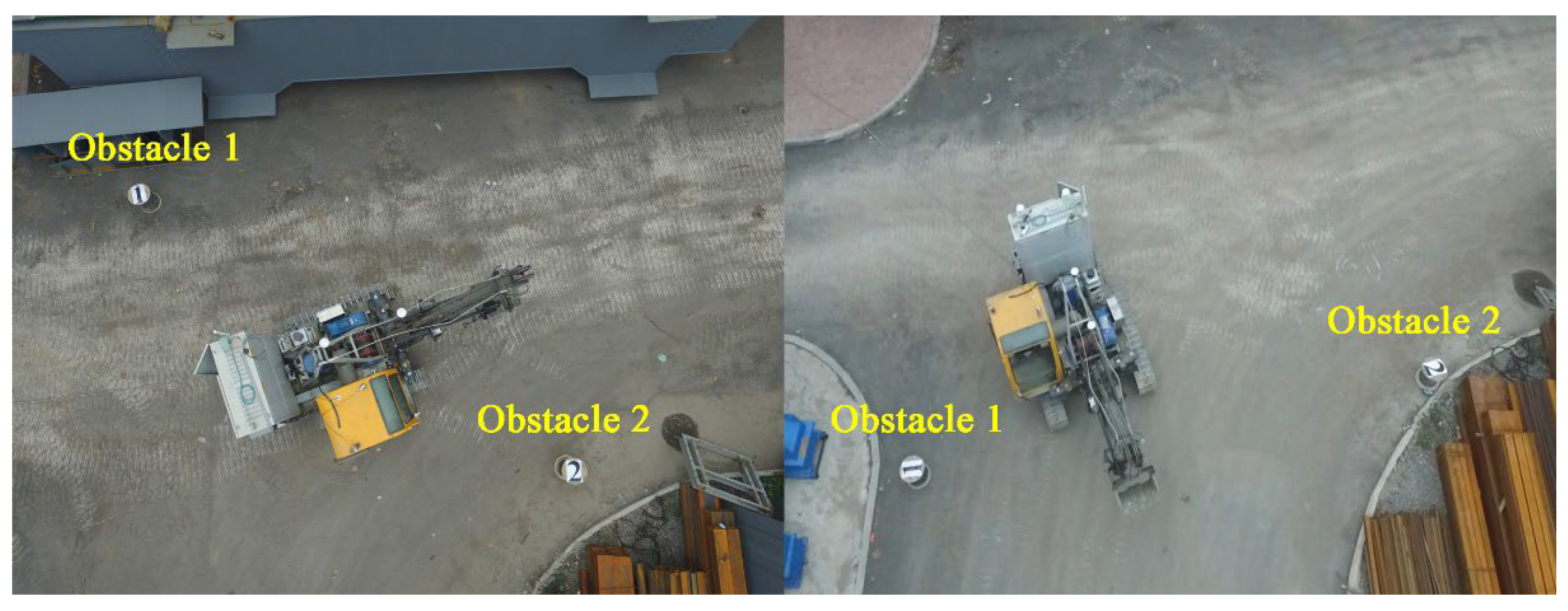
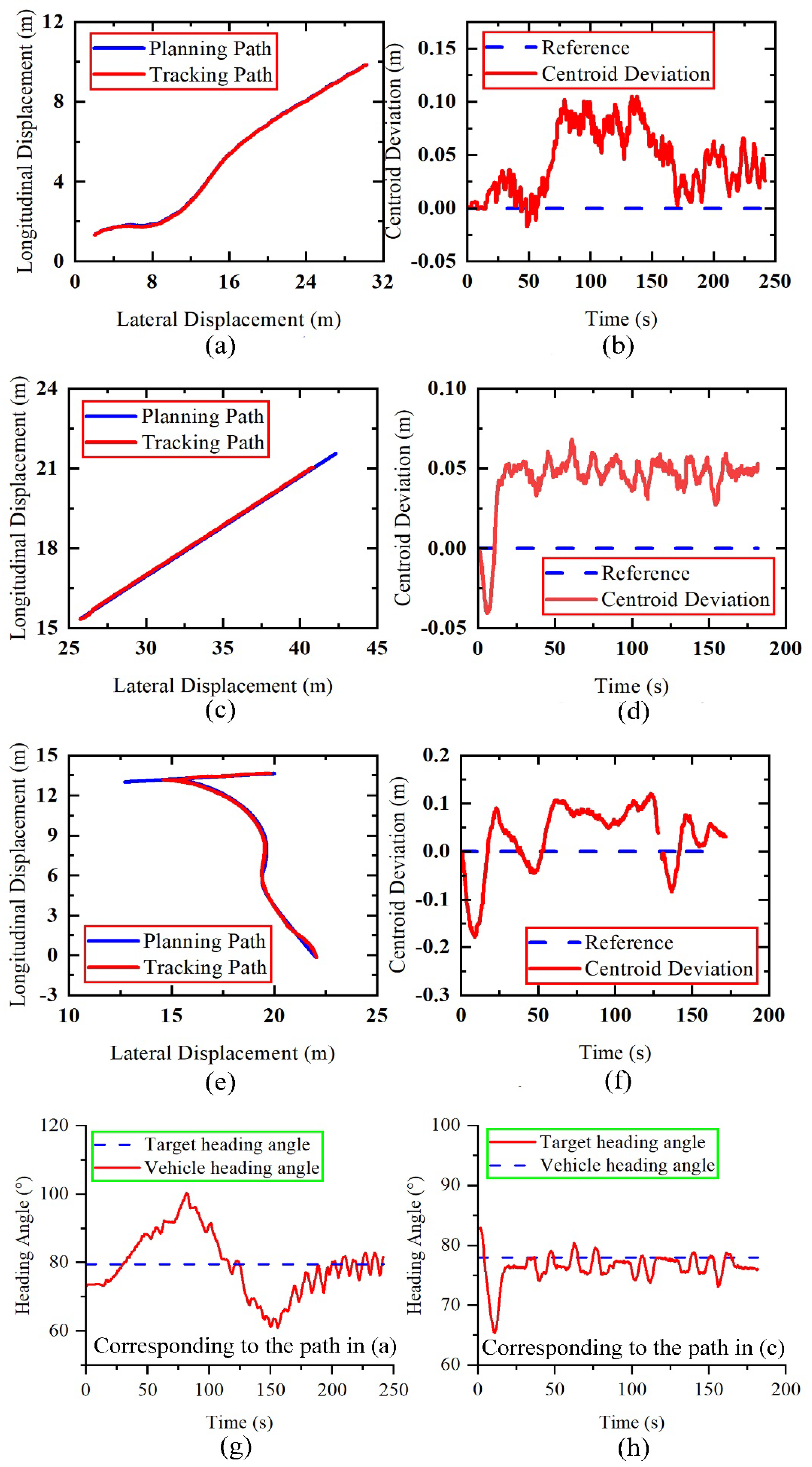
The experimental verification is carried out based on the three basic working conditions of ES movement. The scene pictures during the experiment are shown in Figure 12. The tracking effect and the change of centroid deviation during ES tracking are shown in Figure 13. The coordinates in Figure 13 are related to the location points set by the base station. The default coordinate origin of the RTK module is far away. The longitudinal/transverse displacement is a vast number in the original coordinates. We selected the point about 5 m from the base station as the origin coordinate to process the data. The blue line segment in Figure 13 is the planned path. The red line segment represents the real-time displacement trajectory of the ES. Figure 13a,c are the displacement trajectories during the ES line and curve tracking experiments. It can be seen that most of the two-line segments overlap, and the two trajectories are the same. Comparing Figure 13b,d, it can be seen that when the vehicle is tracking the path, the ES centroid deviation is maintained within 5 cm, and the maximum deviation is 10 cm.
The ES comprises an upper working device and a lower moving device. A slewing mechanism connects the upper and lower parts of the ES. The RTK is installed on the upper part of the shovel. Therefore, RTK measures the heading angle of the working device on the shovel. In the tracking experiment, the preview distance deviation of the track moving mechanism is one of the control quantities. The heading angle calculates the preview distance deviation. At the beginning of the experiment, the heading angle deviation of the upper and lower parts leads to the deviation of the preview distance in the track tracking process, which leads to the deviation in Figure 13f,d.
In Figure 13g, the ES has a relatively large heading angle adjustment in the early stage, and the ES heading angle direction gradually tends to be stable in the later stage. The ES’s heading angle adjustment range is small during straight-line tracking. The changing relationship of real-time heading angles during ES tracking is shown in Figure 13g,h. Figure 13g corresponds to the path of Figure 13a,h, which corresponds to the path of Figure 13c. The first half of path (a) is a curve, and the corresponding heading angle change trend is shown in Figure 13g. It can be seen that when the ES tracks the curve path, the heading angle constantly changes with the path point. The second half of path (a) is a straight line, which is the same as path (c). It can be seen that when the ES tracks the straight path, the heading angle of the ES changes within a small range. The heading angle of the ES will be slightly adjusted until the endpoint is consistent with the target heading angle.
The ES path tracking experiments under all working conditions show that the ES will significantly adjust the heading angle direction at the beginning of tracking to track the preset trajectory quickly. When the center of mass of the ES reaches the preset trajectory, the heading angle change amplitude decreases; the final heading angle is consistent with the target heading angle, and the error range is within 2°. The tracking effect of the ES in a V-shaped reversing condition is shown in Figure 13e. The first 126 s represent the backward part, followed by the forward part. Figure 13f corresponds to the V-shaped working condition. It can be seen from Figure 13f that when the ES is in the process of retreating, the centroid deviation is the same as the curve, and the maximum centroid deviation does not exceed 10 cm. In V-shaped working conditions, the ES must reverse to the midpoint and advance to the target point. When the ES moves to the midpoint position, to reduce the damage to the motor caused by the forward and reverse switching, the motor has to decelerate from reverse to 0 and then rotate forward. The shovel will then begin to track its progress. Therefore, the discontinuity at 120 s is caused by the change of the reference track tracked by the shovel.

5.4. Method Comparison

The PID control algorithm is the most used control algorithm in the industrial field. The algorithm calculates the adjustment amount according to the proportion (P), integral (I), and differential (d) of the deviation between the target value and the actual value. The algorithm principle and implementation are simple, the parameter setting is convenient, and it has good stability and robustness. It is suitable for all kinds of industrial control processes for which it is difficult to obtain accurate models. In order to reflect the advantages of the proposed tracking control algorithm, we use the PID control method to carry out experiments. The control equation of PID is shown in Equation (25):
u ( t ) = K P e ( t ) + 1 T i 0 t e ( t ) d t + T d d e ( t ) d t e ( t ) = r ( t ) c ( t )
In Equation (25) above, K P is the proportional coefficient, mainly used to adjust the system’s accuracy; T i and T d represent differential time constant and integral time constant, respectively; e ( t ) is the deviation between the actual position of the shovel and the preset trajectory; r ( t ) is the initial setting value; c ( t ) is the actual output deviation of the system. The parameters of the PID controller used in the experiment after many adjustments are kp = 800, ki = 100, kd = 300.
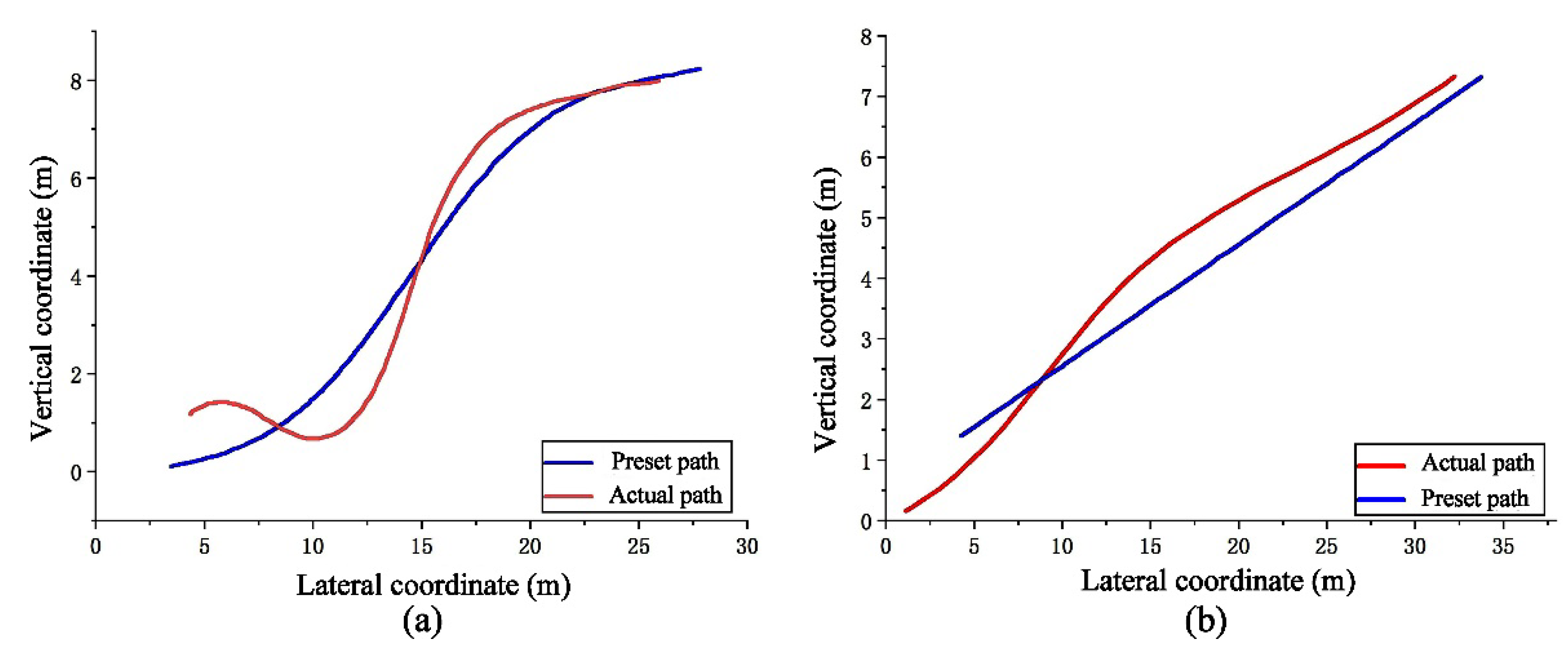
Figure 14 shows the optimal result of the trajectory tracking control experiment with the PID controller. Figure 14a is the curve path tracking, and Figure 14b is linear path tracking. It can be seen from the figure that when tracking a straight line, the shovel cannot finally walk along the track. In the track tracking experiment on the curve track, there is not only a large overshoot but also a situation of unstable tracking. The effect of PID control tracking is poor and cannot meet the tracking conditions. The results of two different control methods prove the superiority of the proposed fuzzy control method based on preview distance and centroid deviation.
Wang Shuai studied the autonomous navigation of six crawler machines. Based on machine vision, he wrote a fuzzy proportional integral derivative control algorithm in the control system to control the six crawler machines as they travel along the guideline. He also built a scaled-down physical prototype of the six-crawler machine and tested it. The scale of the prototype is 1:34. The size of the reduced scale prototype is small. The tracking distance deviation of the dynamic simulation is within 0.14 m. The final distance deviation of the six-crawler scale prototype experiment under the curve condition is dynamically adjusted between 0 and 0.1 m [25]. It can be seen from the above experimental results of the ES that the method proposed in this paper has more advantages in heavy track control than the results of six-track tracking. The ES prototype used in this paper is closer to the real one. The volume size of the ES is about 100 times that of the six-crawler scale prototype. The deviation of the center of mass distance during tracking is stable at about 0.05 m, and the maximum is not more than 0.1 m.

6. Conclusions

In this paper, the research on the unmanned walking of intelligent ESs is carried out. Based on the improved APF algorithm, the obstacle-free path between an ES from the current position to the target position is planned, and the path planning simulation verification of various obstacle maps is carried out. For the trajectory tracking method of an ES, a fuzzy control strategy based on preview deviation and centroid deviation is proposed. The robustness of the tracking algorithm is verified by multi-condition simulation. Finally, an ES prototype is carried out through path planning and tracking experiments of various basic working conditions. The experimental results show that the improved APF algorithm can plan an unobstructed path that satisfies the ES movement. The ES can quickly adjust the heading angle and speed to track the preset trajectory. Beyond 10 cm, the heading angle deviation of the ES reaching the end of the trajectory is within 2°.
In addition, the proposed path planning and trajectory tracking method can also be applied to other heavy crawler construction machinery, such as hydraulic excavators, mobile crushing stations, etc., which is beneficial to improving their mobile efficiency and automation level.

Author Contributions

Conceptualization, Y.F. and S.W.; methodology, Y.F. and Q.B.; software, G.W. and W.G.; validation, C.Y., S.W. and Q.B.; formal analysis, Y.F.; investigation, Y.W.; resources, W.G.; data curation, Y.W.; writing—original draft preparation, Y.F.; writing—review and editing, Y.F.; visualization, W.G.; project administration, C.Y.; funding acquisition, S.W. and Q.B. All authors have read and agreed to the published version of the manuscript.

Funding

This work was funded by the Shanxi Science and Technology Major Project (Grant Number 20191101014), and the Youth Foundation of China (52105100).

Institutional Review Board Statement

Not applicable.

Informed Consent Statement

Not applicable.

Data Availability Statement

All data are available in the main text or the corresponding author.

Conflicts of Interest

The author declares that there is no conflict of interest.

References

  1. Bi, Q.; Wang, G.; Wang, Y.; Yao, Z.; Hall, R. Digging Trajectory Optimization for Cable Shovel Robotic Excavation Based on a Multi-Objective Genetic Algorithm. Energies 2020, 13, 3118. [Google Scholar] [CrossRef]
  2. Ghodrati, B.; Hoseinie, S.H.; Garmabaki, A.H.S. Reliability considerations in automated mining systems. Int. J. Min. Reclam. Environ. 2015, 29, 404–418. [Google Scholar] [CrossRef]
  3. Valenzuela Guzman, M.; Anibal Valenzuela, M. Integrated Mechanical-Electrical Modeling of an AC Electric Mining Shovel and Evaluation of Power Requirements During a Truck Loading Cycle. IEEE Trans. Ind. Appl. 2015, 51, 2590–2599. [Google Scholar] [CrossRef]
  4. Tubis, A.A.; Werbińska-Wojciechowska, S.; Góralczyk, M.; Wróblewski, A.; Ziętek, B. Cyber-Attacks Risk Analysis Method for Different Levels of Automation of Mining Processes in Mines Based on Fuzzy Theory Use. Sensors 2020, 20, 7210. [Google Scholar] [CrossRef]
  5. Li, X.; Liu, C.; Li, J.; Baghdadi, M.; Liu, Y. A Multi-Sensor Environmental Perception System for an Automatic Electric Shovel Platform. Sensors 2021, 21, 4355. [Google Scholar] [CrossRef]
  6. Sebastian, B.; Ben-Tzvi, P. Physics Based Path Planning for Autonomous Tracked Vehicle in Challenging Terrain. J. Intell. Robot. Syst. 2019, 95, 511–526. [Google Scholar] [CrossRef]
  7. Kim, J.; Lee, D.-e.; Seo, J. Task Planning Strategy and Path Similarity Analysis for An Autonomous Excavator. Autom. Constr. 2020, 112, 103108. [Google Scholar] [CrossRef]
  8. Guan, T.; He, Z.; Manocha, D.; Zhang, L. TTM: Terrain Traversability Mapping for Autonomous Excavator Navigation in Unstructured Environments. arXiv 2021. [CrossRef]
  9. Hu, J.; Wang, M.; Zhao, C.; Pan, Q.; Du, C. Formation control and collision avoidance for multi-UAV systems based on Voronoi partition. Sci. China-Technol. Sci. 2020, 63, 65–72. [Google Scholar] [CrossRef]
  10. Huang, Y.; Ding, H.; Zhang, Y.; Wang, H.; Cao, D.; Xu, N.; Hu, C. A Motion Planning and Tracking Framework for Autonomous Vehicles Based on Artificial Potential Field Elaborated Resistance Network Approach. IEEE Trans. Ind. Electron. 2020, 67, 1376–1386. [Google Scholar] [CrossRef]
  11. Lin, P.; Choi, W.Y.; Yang, J.H.; Chung, C.C. Waypoint Tracking for Collision Avoidance Using Artificial Potential Field. In Proceedings of the 39th Chinese Control Conference (CCC), Shenyang, China, 27 July 2020. [Google Scholar]
  12. Lin, P.; Choi, W.Y.; Chung, C.C. Local Path Planning Using Artificial Potential Field for Waypoint Tracking with Collision Avoidance. In Proceedings of the 2020 IEEE 23rd International Conference on Intelligent Transportation Systems (ITSC), Rhodes, Greece, 20–23 September 2020; pp. 1–7. [Google Scholar]
  13. Nazarahari, M.; Khanmirza, E.; Doostie, S. Multi-objective multi-robot path planning in continuous environment using an enhanced genetic algorithm. Expert Syst. Appl. 2019, 115, 106–120. [Google Scholar] [CrossRef]
  14. Huang, Q.M.; Chen, Y.H.; Cheng, A.G. Adaptive Robust Control for Fuzzy Mechanical Systems: Constraint-Following and Redundancy in Constraints. IEEE Trans. Fuzzy Syst. 2015, 23, 1113–1126. [Google Scholar] [CrossRef]
  15. Wang, D.; Lin, X.; Zhang, Y. Fuzzy logic control for a parallel hybrid hydraulic excavator using genetic algorithm. Autom. Constr. 2011, 20, 581–587. [Google Scholar] [CrossRef]
  16. Hanh, L.D.; Ahn, K.K.; Kha, N.B.; Jo, W.K. Trajectory control of electro-hydraulic excavator using fuzzy self tuning algorithm with neural network. J. Mech. Sci. Technol. 2009, 23, 149–160. [Google Scholar] [CrossRef]
  17. Liu, X.; Zhang, M.; Rogers, E. Trajectory Tracking Control for Autonomous Underwater Vehicles Based on Fuzzy Re-Planning of a Local Desired Trajectory. IEEE Trans. Veh. Technol. 2019, 68, 11657–11667. [Google Scholar] [CrossRef]
  18. Zhang, T.; Fu, T.; Song, X.; Qu, F. Multi-objective excavation trajectory optimization for unmanned electric shovels based on pseudospectral method. Autom. Constr. 2022, 136, 104176. [Google Scholar] [CrossRef]
  19. Tota, A.; Velardocchia, M.; Rota, E.; Novara, A. Steering Behavior of an Articulated Amphibious All-Terrain Tracked Vehicle. In Proceedings of the WCX SAE World Congress Experience, Detroit, MI, USA, 21–23 April 2020. [Google Scholar]
  20. Tota, A.; Galvagno, E.; Velardocchia, M. Analytical Study on the Cornering Behavior of an Articulated Tracked Vehicle. Machines 2021, 9, 38. [Google Scholar] [CrossRef]
  21. Sharma, K.; Doriya, R. Coordination of multi-robot path planning for warehouse application using smart approach for identifying destinations. Intell. Serv. Robot. 2021, 14, 313–325. [Google Scholar] [CrossRef]
  22. Dunbabin, M.; Corke, P. Autonomous excavation using a rope shovel. J. Field Robot. 2006, 23, 379–394. [Google Scholar] [CrossRef]
  23. Kathib, O. Real-Time Obstacle Avoidance for Manipulators and Mobile Robots; Springer: New York, NY, USA, 1986. [Google Scholar] [CrossRef]
  24. Zhou, Z.; Wang, J.; Zhu, Z.; Yang, D.; Wu, J. Tangent navigated robot path planning strategy using particle swarm optimized artificial potential field. Optik 2018, 158, 639–651. [Google Scholar] [CrossRef]
  25. Wang, S.; Ge, H.; Ma, R.; Cui, D.; Liu, X.; Zhang, S. Study on the visual tracking control technology of six-crawler machine. Proc. Inst. Mech. Eng. Part C-J. Mech. Eng. Sci. 2019, 233, 6051–6075. [Google Scholar] [CrossRef]
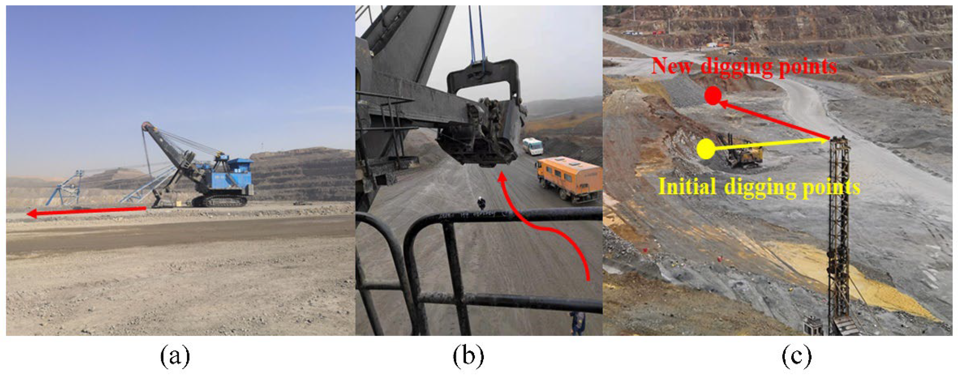
Figure 1. Driving conditions of ES. (a) Straight condition; (b) Curve driving condition; (c) ’’V’’ type driving condition.
Machines 10 00707 g001
Figure 2. Disadvantages of APF.
Machines 10 00707 g002
Figure 3. Improved APF path planning.
Machines 10 00707 g003
Figure 4. Multi−condition simulation of path planning. (a) Complex curve boundary; (b) Common curve boundary; (c) Common V-shaped boundary;(d) Complex V-shaped boundary.
Machines 10 00707 g004
Figure 5. ES movement analysis. (a) Steering movement; (b) Plane movement.
Machines 10 00707 g005
Figure 6. ES trajectory tracking diagram. (a) Trajectory tracking; (b) Tracking method model.
Machines 10 00707 g006
Figure 7. ES trajectory tracking method.
Machines 10 00707 g007
Figure 8. Membership function of input and output. (a) Deviation rate of change ( e c ); (b) Lateral displacement deviation ( e ); (c) Output speed difference ( ν ).
Machines 10 00707 g008
Figure 9. Trajectory tracking simulation. (a) The initial position is on the right; (b) The initial position is on the left; (c) Centroid deviation; (d) Heading angle deviation.
Machines 10 00707 g009
Figure 10. ES experimental prototype.
Machines 10 00707 g010
Figure 11. ES unmanned walking control structure.
Machines 10 00707 g011
Figure 12. ES experimental environment.
Machines 10 00707 g012
Figure 13. Experimental results of ES trajectory planning and path tracking. (a) Curve tracking path; (b) Curve tracking centroid deviation; (c) Line tracking path; (d) Straight line tracking centroid deviation; (e) V-shaped tracking path; (f) V-shaped tracking centroid deviation; (g) Curve tracking heading angle deviation; (h) Straight line tracking heading angle deviation.
Machines 10 00707 g013
Figure 14. Experimental results of PID trajectory tracking control. (a) Curve tracking path; (b)Line tracking path.
Machines 10 00707 g014
Table 1. Fuzzy control rule table.
v e
NBNMNSZEPSPMPB
e c NBNBNBNMNMNSNSZE
NMNBNMNMNSNSZEPS
NSNMNMNSNSZEPSPS
ZENMNSNSZEPSPSPM
PSNSNSZEPSPSPMPM
PMNSZEPSPSPMPMPB
PBZEPSPSPMPMPBPB
Table 2. Sensor parameters.
Sensor NameSensor ModelSensor AccuracyFrequency
RTKP3-DU Beidou GNSSPositioning accuracy: centimeter level
Direction finding accuracy ≤ 0.2°
10 Hz
LidarRoboSense:
Number of lines: 80
Horizontal angular resolution 0.2°/0.4°
Vertical angular resolution Up to 0.1°
Accuracy (typical value) Up to ±3 cm
20 Hz
Publisher’s Note: MDPI stays neutral with regard to jurisdictional claims in published maps and institutional affiliations.