1. Introduction
With the advent of permanent magnet synchronous motors (PMSMs), these high-efficiency devices have been widely used in diverse industries such as EV and wind power generation [
1]. The unique arrangement and structural characteristics of hub motors have a significant effect on improving the overall performance of vacuum pumps. In this regard, the PMSM has superior characteristics such as a high power density, large torque inertia ratio, and fast dynamic response. Accordingly, this type of motor has become one of the best choices for vacuum pumps. As the direct power source of vacuum pumps, the motor drive performance directly affects the overall performance of the system. Recently, investigating the vacuum pumps’ drive technology for industry has attracted many scholars, and it has become a research hot spot [
2].
The high-performance drive control strategy for a PMSM relies on accurate rotor position information, which is usually measured by position sensors. However, the use of position sensors in the motor system has many challenges such as high installation accuracy, high costs, and low reliability. Aiming at resolving these problems, the position sensorless control technology was proposed, in which the position and speed of the motor rotor can be obtained without installing expensive mechanical sensors, thereby eliminating the problems caused by position sensors [
3,
4].
In the PMSM position sensorless control system, the position estimation algorithms mainly include the high-frequency injection method [
5,
6,
7], sliding mode observer [
8,
9,
10,
11,
12,
13], model reference adaptive system [
14,
15,
16], and extended Kalman observer [
17]. Studies show that the sliding mode observer is insensitive to the variation of motor parameters and has a strong robustness, low computational cost, and simple implementation, and so it has been widely used in PMSM sensorless control systems.
In [
8], the paper proposed an adaptive second order sliding mode observer (SMO) to estimate the position of the surface-mounted PMSM, and VSI non-linearity is considered. In the process, the mismatch between reference and actual voltage was inhibited, especially at a low speed, and the distortion became dominant. L. Ding proposed an improved SMO which adopted an in-current source, converter-fed PMSM. In the paper, the researchers proposed a multi-loop controller having a capacitor voltage control combined with a discrete-time sliding mode observer sensorless strategy and an adaptive filter [
9]. It effectively improved the accuracy of the rotor speed and position estimation and the robustness of the system. Ye S. proposed an enhanced SMO method which featured current measurement error compensation, and a hyperbolic tangent switching function-based SMO was introduced with a self-adjusted shape coefficient and a fuzzy logic controller to eliminate the low pass filter and angular compensator of a traditional SMO to reduce the chatter caused by the constant boundary layer thickness [
10]. Wang Y. designed a robust adaptive SMO in a rotor reference frame, and an adaptive law was presented in a small signal model, which made the steady-state and dynamic behavior of the sensorless scheme perform excellently [
11]. Shen J. Q. proposed a magnetic chain SMO for an interior PMSM in which a soft phase-locked loop flux observer was used to estimate the speed and position of the rotor [
12]. The obtained results showed that this method effectively eliminates the low-pass filter and phase compensation module and improves the estimation accuracy of the rotor position. Fan L. proposed a sensorless control method based on an adaptive sliding mode observer in the PMSM drive control of a turboprop aircraft. In this method, the phase-locked loop was used to estimate the rotor angle and eliminate the phase delay caused by the low-pass filter, which improved the performance of conventional sliding mode observers [
13].
The performed literature survey indicates that most of the SMOs estimate the speed and position in a static two-phase coordinate system. Therefore, the estimation accuracy can be improved by adding a low-pass filter and a phase compensation module. However, this modification increases the complexity of the control system. Moreover, when there is a phase lag between the estimated and actual coordinate system while the observer is running, estimation errors are inevitable. To solve these problems in the PMSM sensorless control system based on a sliding mode observer, a super-twisting sliding mode observer based on a rotating coordinate system is designed, and a speed estimation algorithm considering the direct axis (d-axis) estimation of back EMF is proposed in the present study. Then, the proposed super-twisting sliding mode observer and speed estimation algorithm are simulated and verified by experiments.
2. Mathematical Model of the PMSM
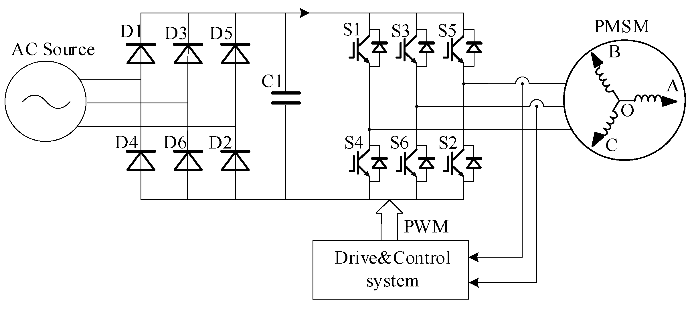
A three-phase PMSM is considered as the research object. The topology of the PMSM driven with an inverter is shown in
Figure 1, where the main circuit contains a three-phase diode rectifier and a 380 V AC source, DC bus, three-phase inverter, PMSM, and hall.
To simplify the analysis, it is usually assumed that the distribution of the permanent magnetic field of the rotor in the air gap of the motor has a sine waveform. Neglecting the saturation effect of the stator core, it can be assumed that the magnetic circuit on the stator is linear and the inductance parameters will not change during operation. Moreover, core eddy current and hysteresis losses are ignored, and it is assumed that there is no damping winding on the rotor.
Under the premise of the above assumptions, the following voltage equation can be established for the PMSM in the synchronous rotating frame through the space vector decoupling transformation:
where
ud and id are the voltage and current along the d-axis,
uq and
iq are the voltage and current along the q-axis, and
Ld and
Lq are the stator inductances along the d-axes and q-axes. In a surface-mounted PMSM,
Ld = Lq,
Rs is the stator resistance,
ωre is the electrical angular speed, and
is the permanent magnet flux linkage.
After space vector decoupling transformation, the component in the zero-sequence subspace is 0. After performing the Park transform in the d-q frame, the α-β subspace contains the fundamental component and harmonics, which are at the multiples of the 6
k ± 1 th-order. The observed current by the three-phase PMSM is presented in Equations (2) [
18] and (3), respectively:
where
θ1 and
I1 are the initial phases and fundamental amplitude,
θ6k±1 and the harmonics of
I6k±1 are the initial phases and amplitudes of the harmonics. The comparison of
Equation (2) reveals that the amplitude of harmonics in the d-q axis current observed in the PMSM is smaller, which is conducive to the design of the super-twisting sliding mode observer in the d-q frame.
3. Rotational Speed Estimation Based on the Super-Twisting Sliding Mode Observer
3.1. Design of the Conventional Sliding Mode Observer
The current equation for the PMSM in the α-β frame can be expressed as follows:
where the
and Equation (3) is for a saliency and non-saliency PMSM, while in this paper, the surface-mounted PMSMs are referred, and so Equation (3) can be simplified to Equation (4):
The state equation of the conventional sliding mode observer is:
Subtracting Equation (4) from Equation (5), the current error dynamic equation can be obtained in the form below:
where
The estimated expressions for the rotational speed and angle are:
It is worth noting that the controlled variable in the sliding mode control is a discrete high-frequency switching signal, and so there is chattering in the observed back EMF. The arctangent operation of Equation (8) and the square root operation of Equation (9) will bring the chattering into the speed estimation and angle estimation.
3.2. Design of the Super-Twisting Sliding Mode Observer
To suppress the chattering caused by high-frequency switching signals during the observation process and reduce the load effect on the speed estimation, a super-twisting sliding mode observer in the d-q coordinate system is proposed. The super-twisting algorithm [
19] is a second-order sliding mode control algorithm which can be mathematically expressed as follows:
where
k and
a are the gain coefficients of the super-twisting sliding mode observer.
The current state equation of the PMSM in the d-q frame is:
Where and are the back EMFs in the d-q frame.
The state equation of the super-twisting sliding mode observer in the d-q frame can be expressed as the following:
The estimated back EMF in the super-twisting sliding mode observer is:
where
is the estimated value of the d-axis current,
is the estimated value of the q-axis current,
is the estimated value of the rotational speed,
,
, and sat is a saturation function with a limiting amplitude of 1. Compared with Equation (8), when using Equation (13) to observe the back EMF, the integral term in the super-twisting sliding mode control algorithm suppresses the chattering of the saturation function and the square root term of the absolute value of the error improves the convergence rate.
Compared with the conventional SMO as shown in Equations (4)–(9), which are based on the α-β frame, the observer of the super-twisting sliding mode observer based on the d-q frame, as shown in Equations (10)–(13), depends on the decoupling voltage relationship of the PMSM. According to super-twisting sliding mode observer shown in Equation (13), it can be seen that the observer is not dependent on the PMSM parameters such as Ld and Lq, and while it depends on the estimated value and real value of the current, the observer guarantees the robustness of the system. This characteristic of the super-twisting sliding mode observer can be widely used in a PMSM system such as a surface-mounted PMSM and an interior permanent magnet (IPM) motor.
When the estimated coordinate system coincides with the actual coordinate system,
and
. However, when the estimated rotational speed at the current moment is applied to the state equation at the next moment, the observation delay will be generated. After the current signal passes through the operational amplifier and the analog-to-digital converter, it will result in a sampling delay. The observation delay and sampling delay will cause the angular deviation
Δθ between the estimated and actual coordinate systems, thereby affecting the estimated value of the back EMF. Meanwhile, the basic relationship between the estimated back EMF and
Δθ can be expressed as:
When the rotational speed is estimated using the expression
, the term cosΔ
θ will increase the estimated value. After controlling the speed’s closed-loop, the actual speed of the motor reduces. To eliminate the estimation error, the influence of the estimated d-axis back EMF on the speed is considered using calculations. Based on Equations (12) and (13), the current dynamic error equation can be expressed as follows:
where
,
,
,
, and
.
3.3. Stability Analysis of the Observer
In this section, the stability of Equation (16) is analyzed by the Lyapunov stability theory. To this end, the Lyapunov function is constructed as follows:
Taking the derivation of Equation (16) yields the following expression:
Substituting Equation (16) into Equation (17), we can obtain:
Considering the influence of the d-axis back EMF on the speed estimation, Equation (18) can be divided into three parts for analysis. To ensure the global asymptotic stability of the current dynamic error equation, Equation (19) should have a negative value. This can be mathematically expressed as follows:
If the current dynamic error equation is globally asymptotically stable, the estimated value of the rotational speed is equal to the actual value, and so
, and Equation (21) holds. Meanwhile, to ensure the stability of the entire current dynamic error equation, the estimated speed can be derived as follows:
Substituting Equation (13) into Equation (22), we can obtain:
Equation (23) indicates that the rotational speed can be estimated using the super-twisting sliding mode algorithm. The integral term in the super-twisting sliding mode control algorithm filters the harmonics in the current errors sd and sq and suppresses the residual error in the observer. The square root of the absolute error value is added to the proportional gain to improve the convergence speed of the speed estimation. Meanwhile, Vd suppresses the speed estimation error caused by the phase lag of the estimated coordinate system.
The estimated angle can be obtained by integrating the estimated rotational speed as follows:
4. Simulation and Experimental Analysis
A super-twisting sliding mode observer is established in the d-q coordinate system. The motor speed value can be estimated using Equation (24). The PMSM is controlled through two current loops and a one-speed loop. A SVPWM modulation algorithm is adopted for the closed-loop control of a PMSM sensorless control system. Considering the PWM delay in the closed loop control system, if the motor is running in a high-speed area or a high electrical frequency area, the delay caused by the switching frequency should be considered, while if the PMSM is operating at a low speed or middle speed area, the delay caused by the PWM can be neglected and only the error of the estimated angle in Equation (14) is taken into account. It should be indicated that these methods are used to verify the effectiveness of the proposed algorithm. The parameters of the PMSM are Rs = 50 mΩ, Ld = Lq = 1.03 mH, = 0.171 Wb, and the number of pole pairs p = 4.
4.1. Simulation Analysis
To simulate the PMSM sensorless control system, the model was established in Matlab/Simulink and he switch frequency
fsw is 10 kHz. The two working conditions of the loading and speed mutation are analyzed. In the former analysis, the rated speed is set to 1000 rpm and a torque of 50 N·m is applied at t = 0.1 s. In the latter analysis, the initial speed is set to 1000 rpm, and then the speed is increased to 1500 rpm at t = 0.2 s and finally returned to 1000 rpm at t = 0.3 s.
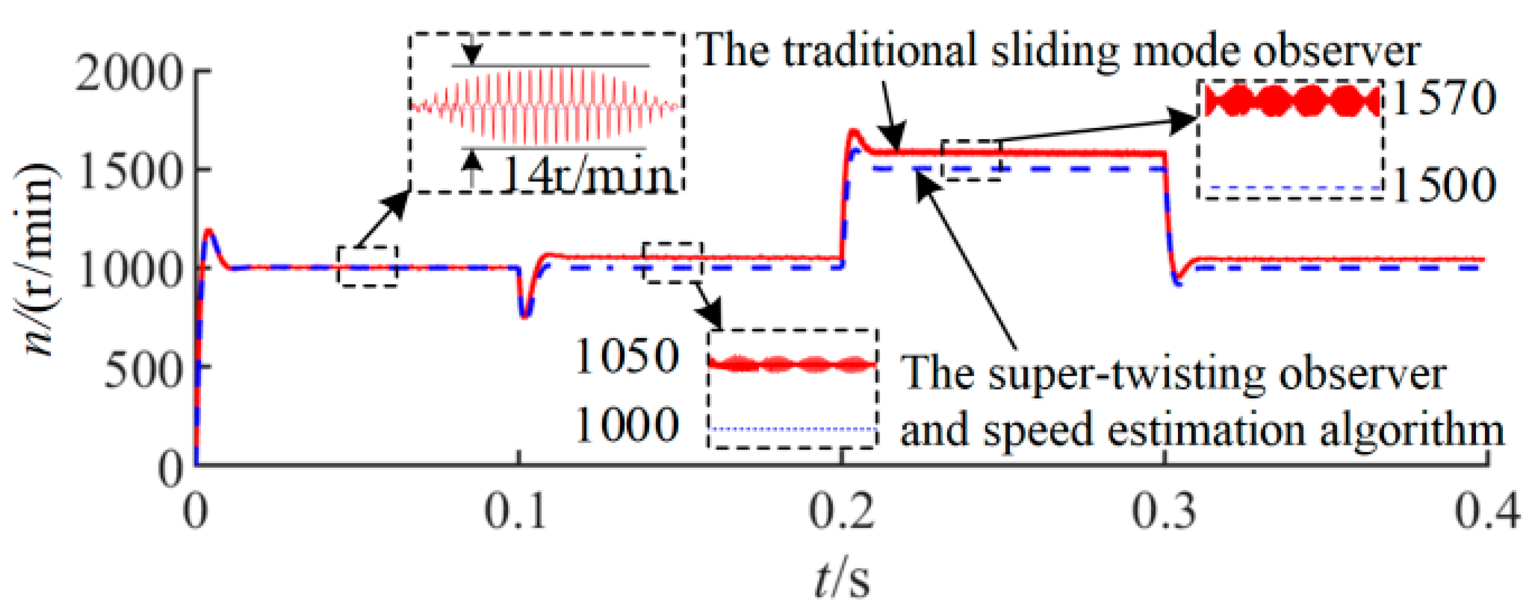
Figure 2 shows the estimated rotational speed curves for the two observers and two working conditions.
Figure 2 reveals that in the steady-state conditions, the sensorless control system equipped with the conventional sliding mode observer has a high-frequency chattering with a peak value of 14 rpm, and there are residual errors of 50 rpm and 70 rpm in the loading and speed mutation conditions, respectively. Compared with the conventional sliding mode observer, the estimated speed in the sensorless control system using the super-twisting observer and the proposed speed estimation algorithm can quickly and accurately follow the actual speed. In this case, there is no high-frequency chattering or estimation error in the estimated speed, which demonstrates the estimation accuracy of the proposed algorithm.
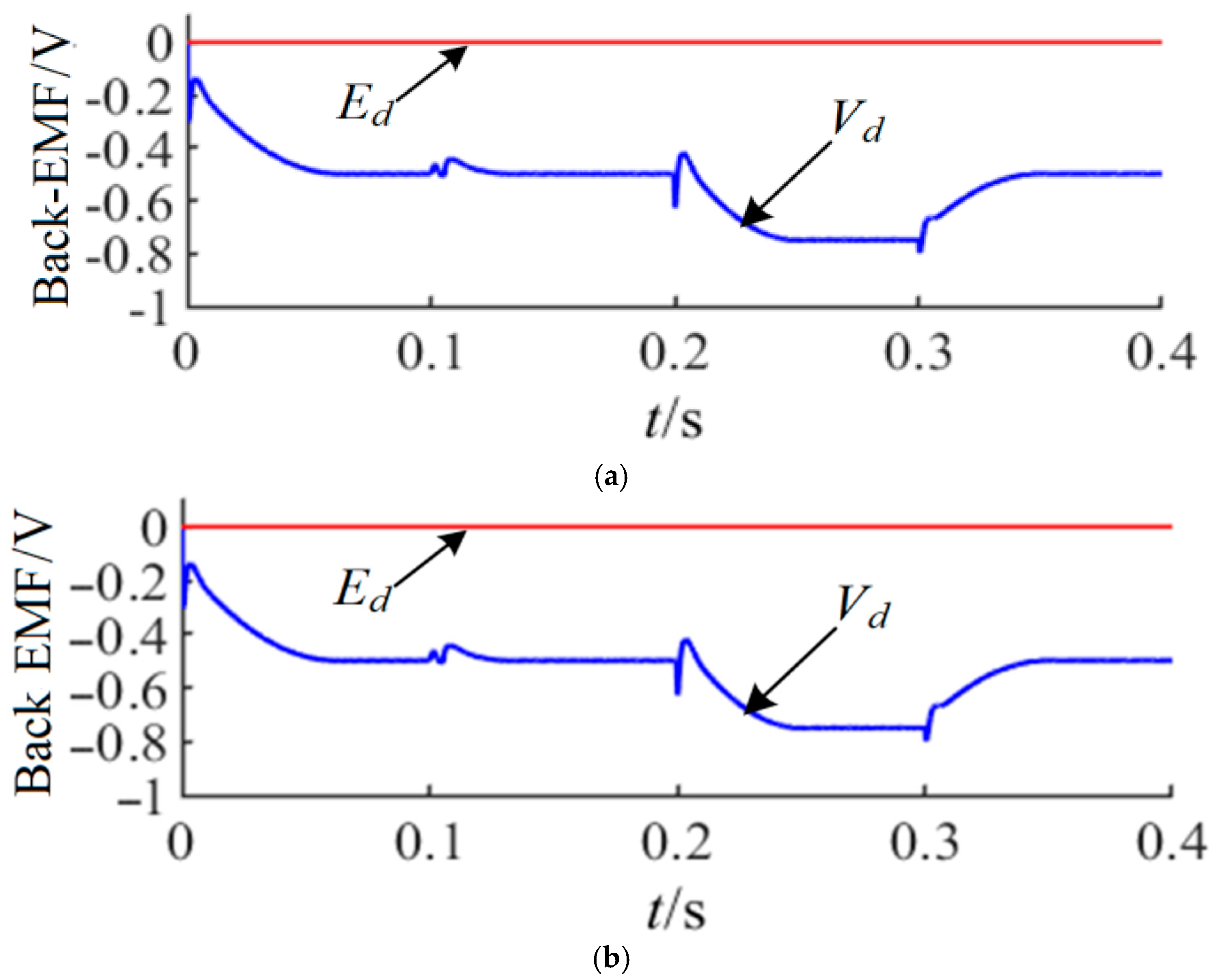
Figure 3 shows the d-q axis back EMF waveform. It can be seen that during the running process of the system, the estimated d-axis back EMF has an error that varies depending on the working conditions. Moreover,
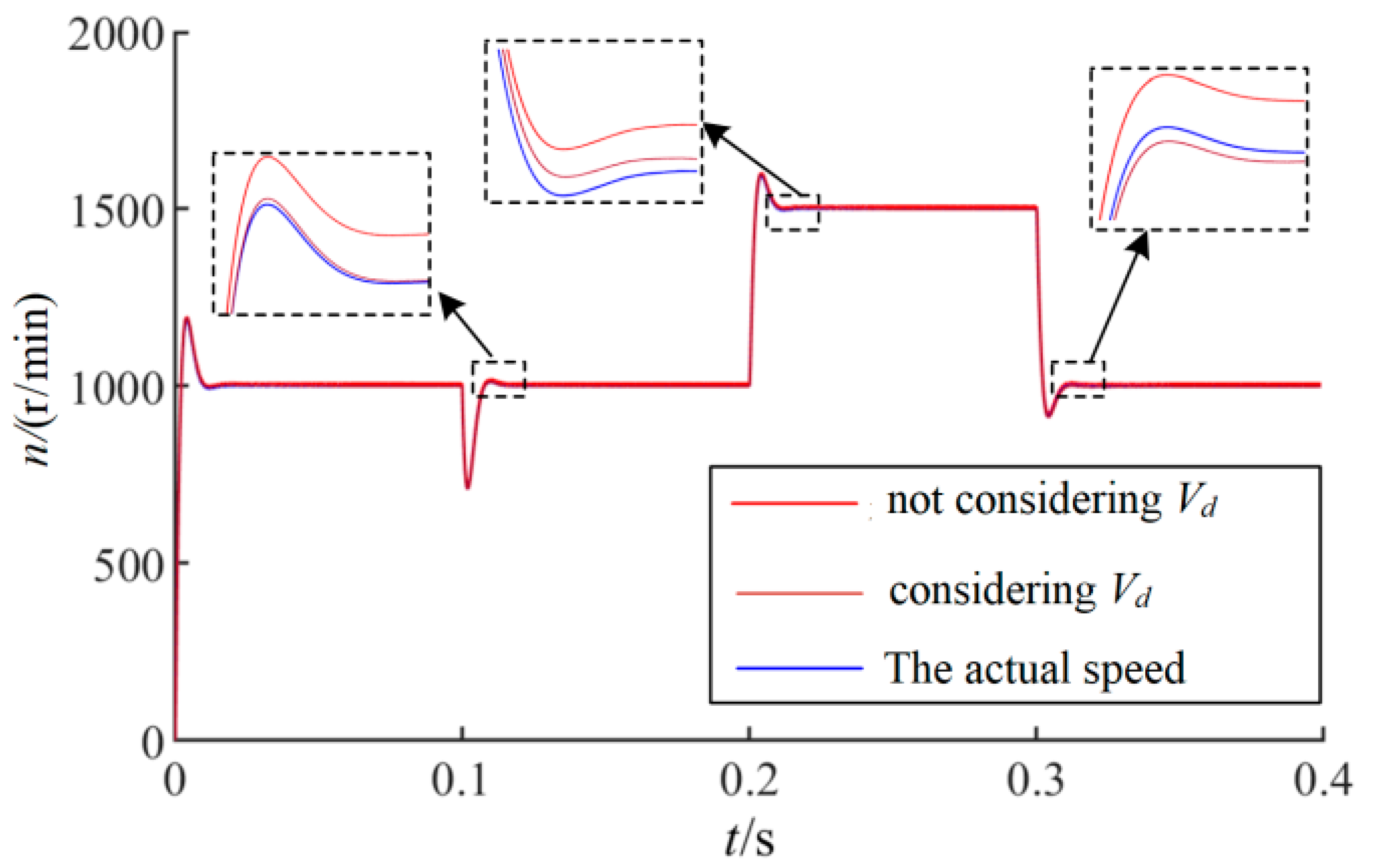
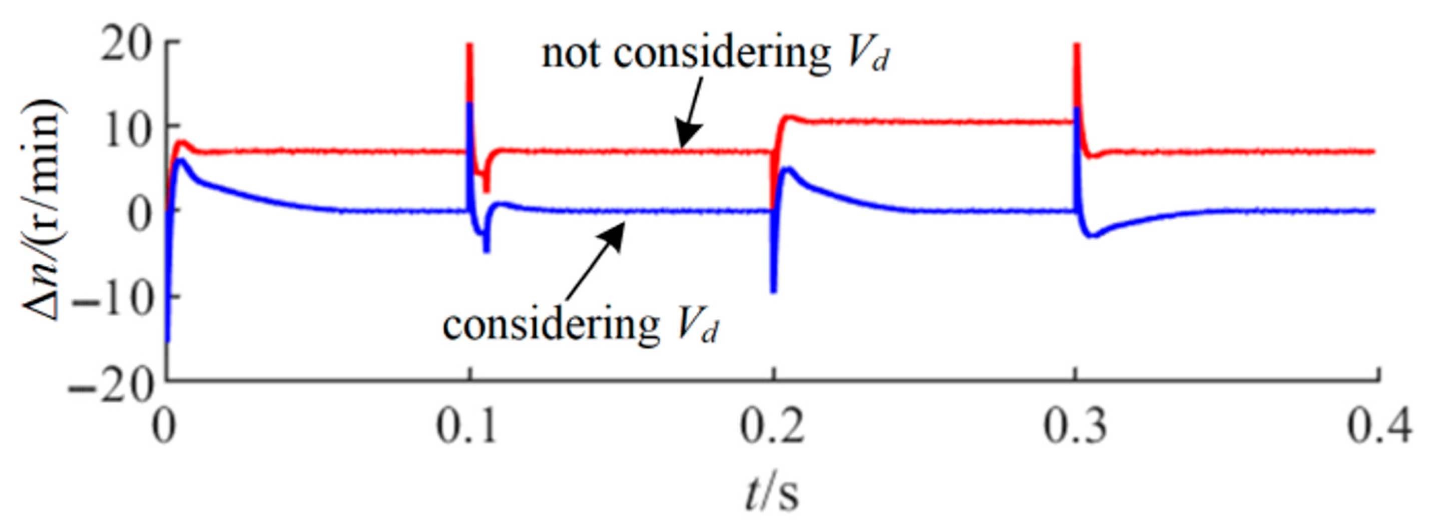
Figure 4 illustrates the comparison curves between the estimated speed and the actual speed, with and without considering
Vd in the calculations, and the lower error when the speed or load is stepped when
Vd is considered. As shown in
Figure 5 in the estimation error curve, the effect of
Vd should be taken into account, and it can be seen that there is a 7 rpm speed error between the real speed and the reference value when it not considered, which is greater in a high-speed area. The speed error is nearly 0 in a steady state when the effect of
Vd is taken into account.
The speed curves in
Figure 4 and the speed estimation error curve in
Figure 5 reveal that when only considering
Vq for speed estimation, the actual speed can be followed. However, there is an error of 0.8% at 1000 rpm. When the operating speed increases to 1500 rpm, the rotation speed error decreases to 0.6%. It is inferred that the correction of
Vd can reduce the speed estimation error and improve the accuracy of the speed estimation.
4.2. Experimental Analysis
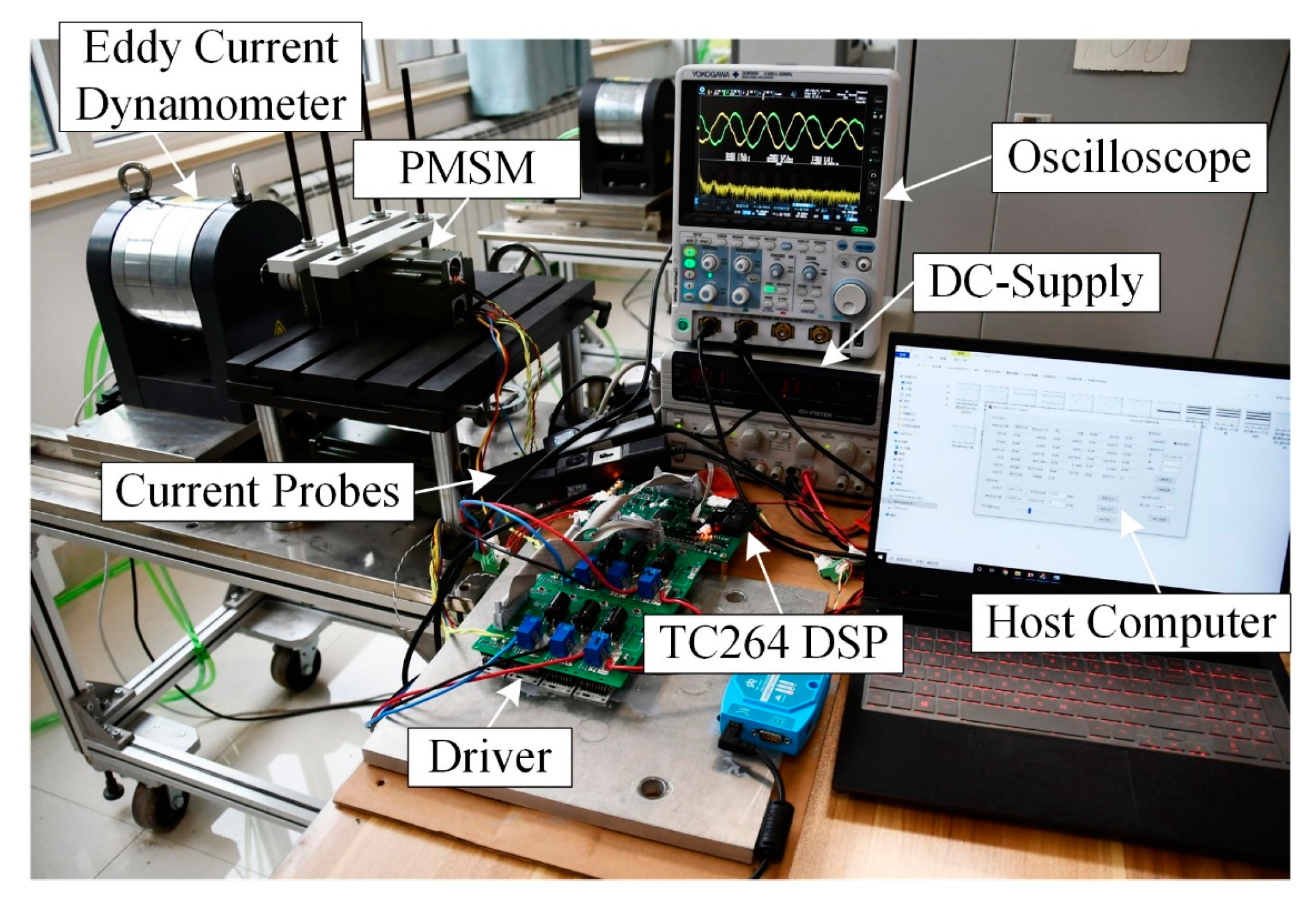
In order to further verify the effectiveness of the proposed algorithm, an experimental platform is built. The experimental platform, shown in
Figure 6, mainly consists of a controller (Haawking DSP HX320 F28034, China), an IGBT switch device (Infineon FF450 R17 ME4, Germany), a current Hall sensor (LEM CASR15-NP, Swiss), and a dynamometer system which is composed of a tension measurement and control (Zhangli 610 L, China) and an eddy current dynamometer (Guangzhong MTS-II, China). High-speed serial communication is used to change the speed command, read the back EMF and speed information of the motor, and record the read data.
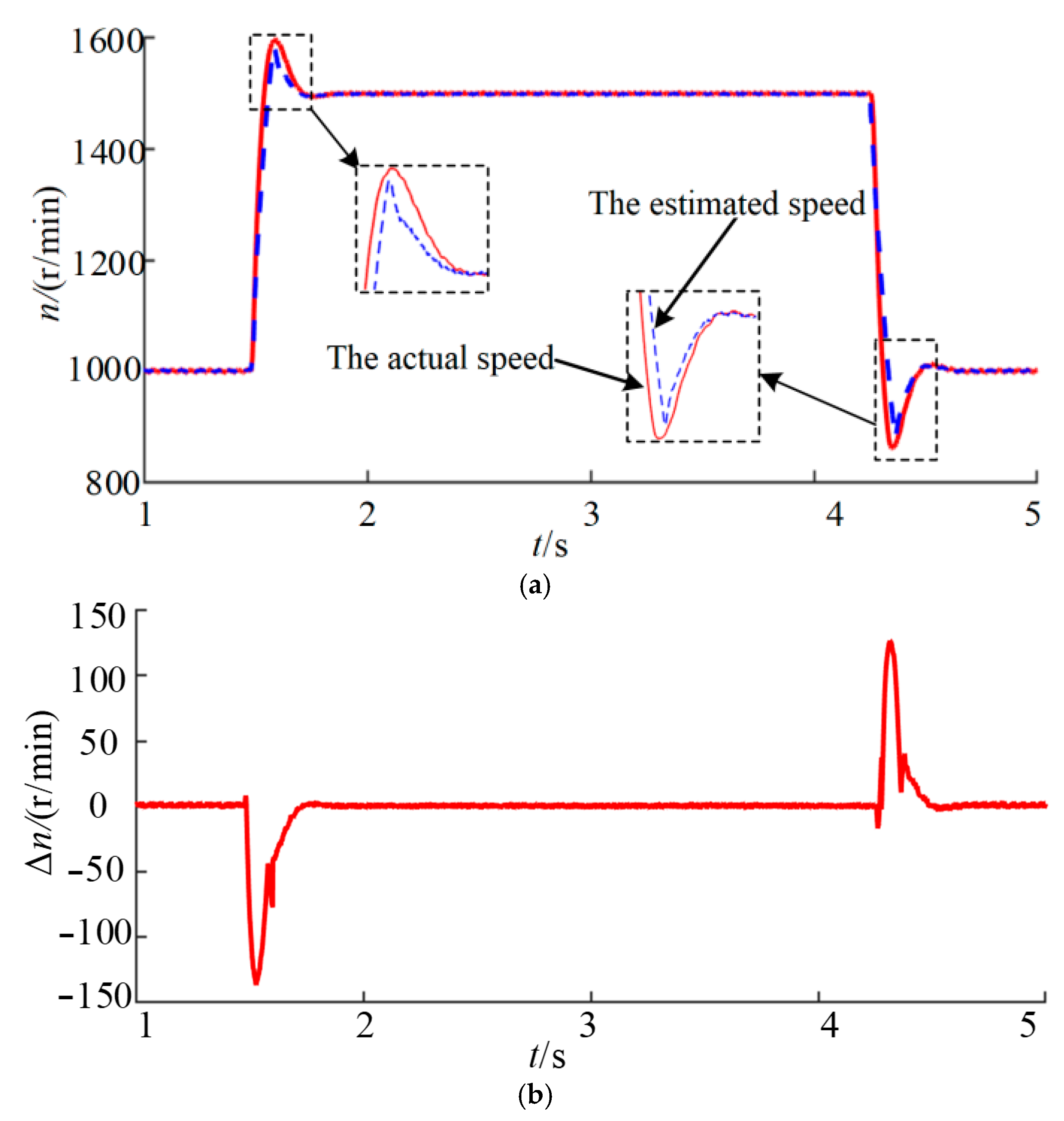
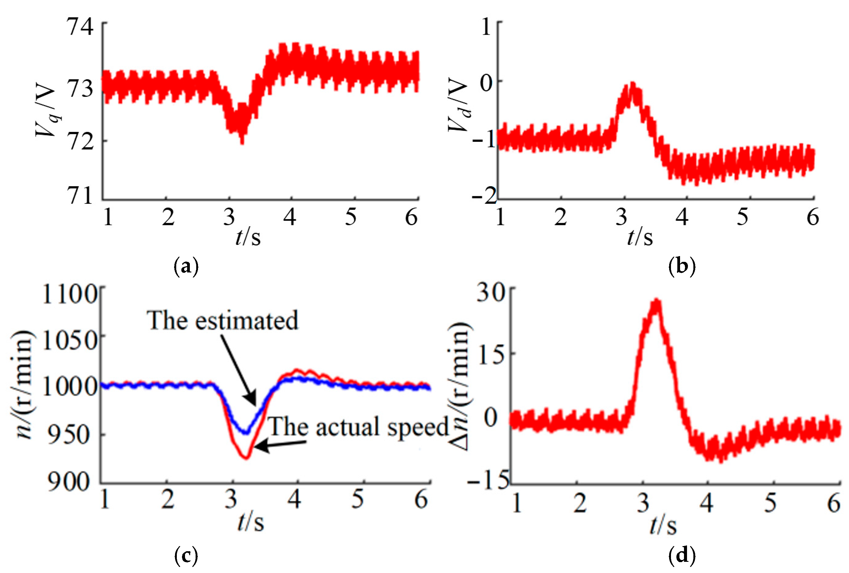
Figure 7 shows the speed curve under the condition of the speed mutation. It is observed that the estimated speed is consistent with the actual speed in real-time when the actual speed changes suddenly. However, the variation trends of
Vd and
Vq in
Figure 8 reveal that there is a rapid convergent oscillation in the convergence process of the speed estimation error. Finally, it becomes stable, and the estimation error is ± 1 rpm.
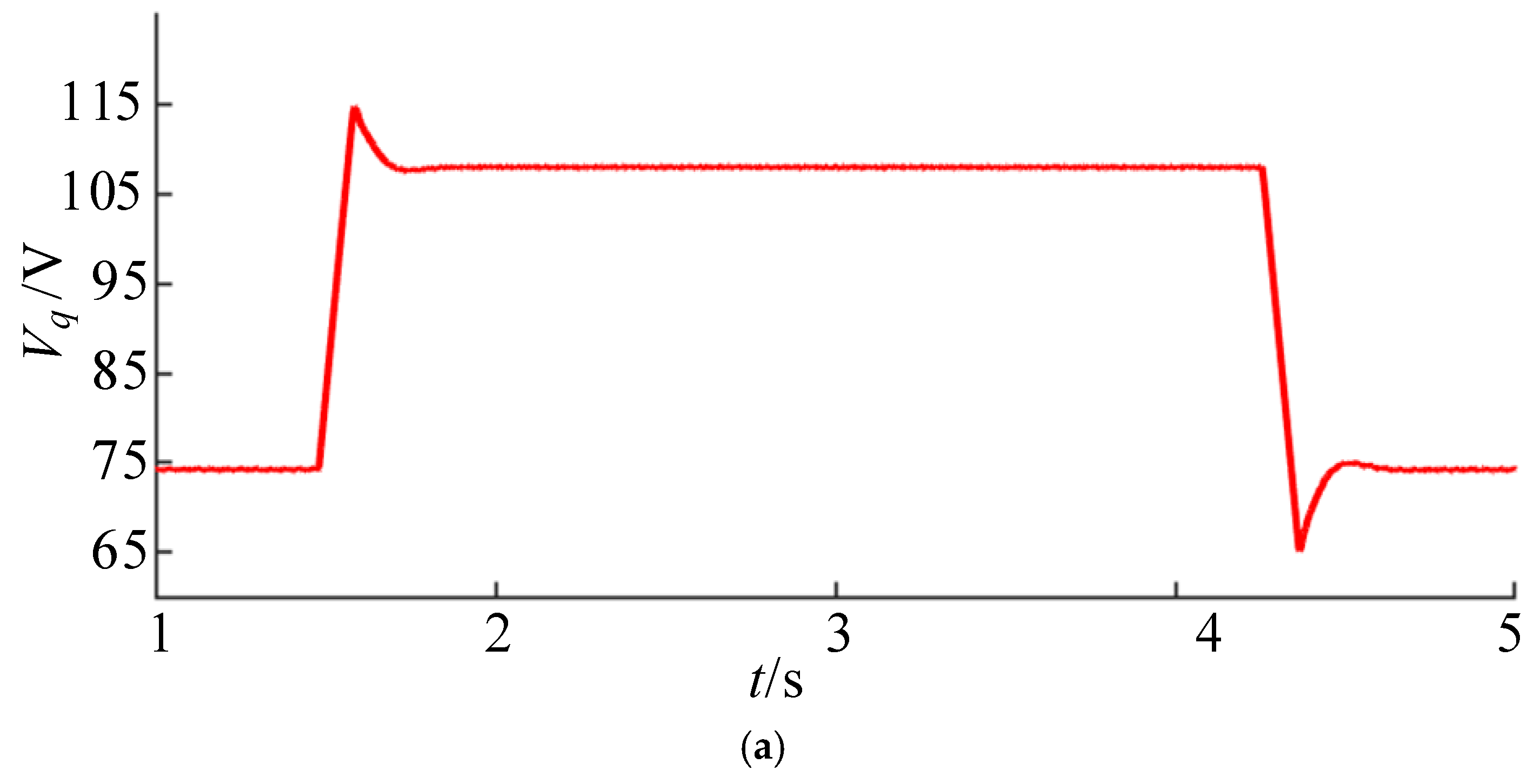
Figure 8 shows the back EMF curve under the condition of the speed mutation. It is observed that as the motor speed increases, the estimated back EMF
Vq is consistent with the actual speed and its stable amplitude rises from 73.0 V to 106.9 V. Moreover, the
Vd peaks increase and the amplitude decreases from −1 V to −2 V after stabilization. Similarly, there is an error between the estimated and actual back EMF as the operating speed decreases. Due to the coupling in the d-q axis voltage equation,
sd and
sq in the super-twisting observation have different trends, and so the trends of
Vd and
Vq are different.
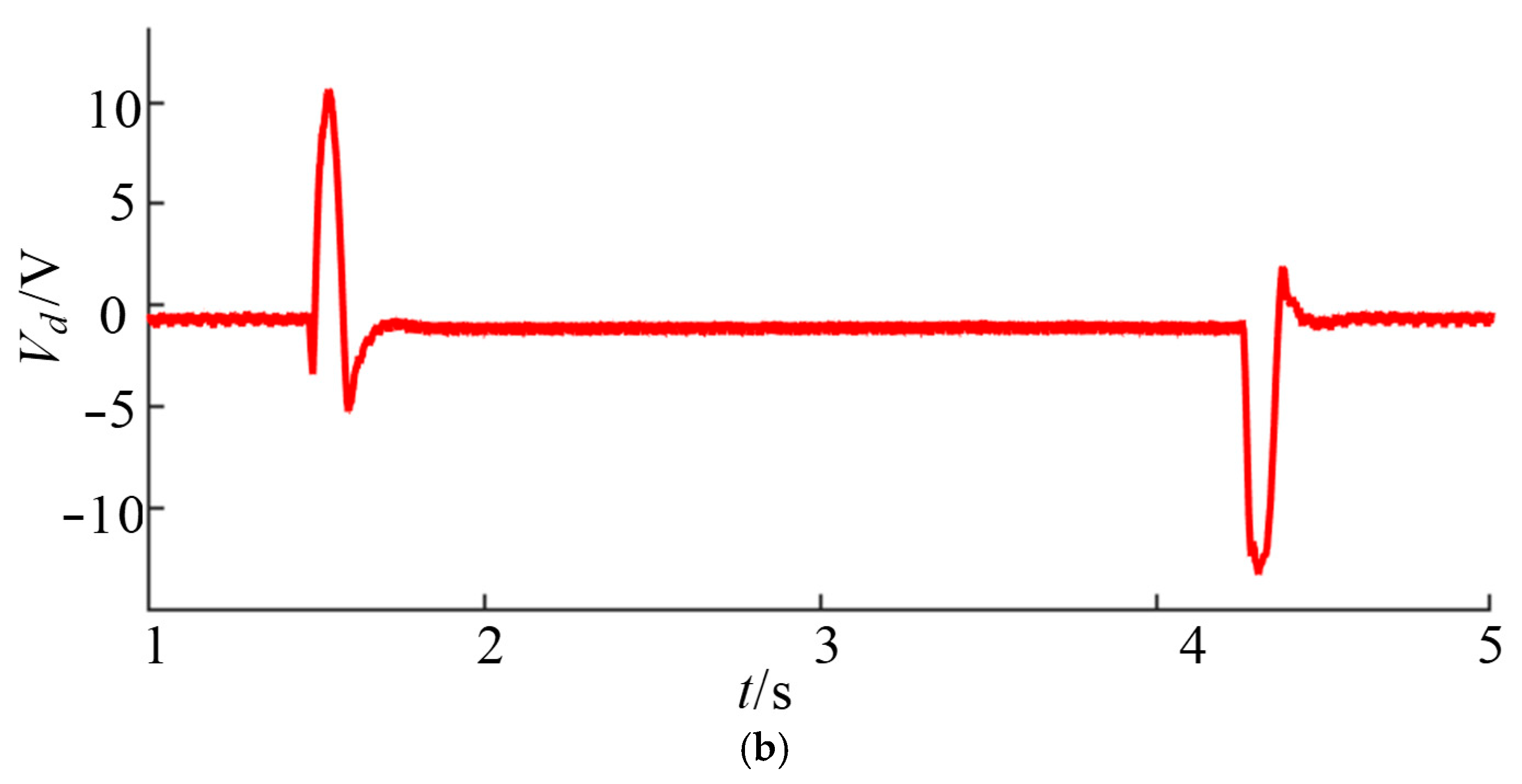
Figure 9 shows the speed curve and back EMF curve under loading conditions. It is observed that after loading, the estimated speed is consistent with the actual speed, but the speed estimation error has a peak of 28 rpm and quickly converges to a stable value. Furthermore, it is found that
Vq and
Vd have amplitude changes of about 0.5 V.
The detected amplitude changes of the rotational speed and estimated back EMF may be attributed to an increase in sq in the super-twisting sliding mode observer when iq increases. The gain coefficient of the super-twisting sliding mode includes the square root of the absolute value of sq, resulting in the amplitude change of Vq. Meanwhile, Vd changes due to the current coupling in the d-q axis voltage equation. According to Equation (22), the estimated speed will change when Vd and Vq change.
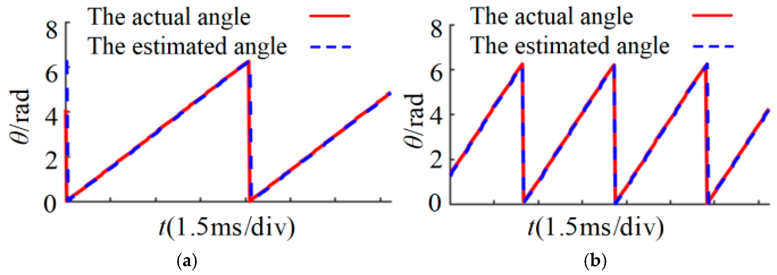
Figure 10 shows the estimated angle curve under the loading and rotational speed mutation conditions. The rotor’s initial position angle is obtained by the pre-position, and the estimated angle is the integral value of the estimated rotational speed.
Figure 10 reveals that the angle estimated using the proposed observer is consistent with the actual angle, but there is a certain phase lag which may originate from the sampling delay and observation delay. This lag is mutually verified with the error of
Vd due to the angle lag in
Figure 8 and
Figure 9.
5. Conclusions
In the present study, a super-twisting sliding mode observer based on a rotating coordinate system is designed, and a new speed estimation algorithm is proposed. Then, the proposed algorithm is applied to the PMSM sensorless control system of vacuum pumps. The feasibility and effectiveness of the algorithm are verified through simulations and experiments. The obtained results demonstrate that the proposed algorithm has the following advantages over the conventional schemes:
- (1)
The d-q axis current is used as the state variable to design the super-twisting sliding mode observer and remove the low-pass filter and phase compensation module. This algorithm can be applied to suppress high-frequency chattering in the conventional sliding mode observer and improve the accuracy of the speed estimation without increasing the system’s complexity.
- (2)
Considering the influence of the phase lag of the estimated coordinate system on the speed estimation error, the introduction of the d-axis estimated back EMF in the speed estimation algorithm reduces the speed estimation error under the loading and speed mutation.
It is concluded that compared with the conventional sliding mode observer, the proposed algorithm can prevent the energy loss caused by system chattering, improve the speed estimation accuracy, and improve the dynamic performance of the PMSM sensorless control system of vacuum pumps.

