Abstract
A method of machining the internal double-arc spiral bevel gear with a finger milling cutter was presented. The mathematical model of the internal spiral bevel gear tooth profile was established considering the principle of machining a spiral bevel gear by the generating method, and a three-dimensional (3D) tooth profile graph was developed. Subsequently, by applying the gear meshing theory, the 3D model of the tooth alignment curve for the finger milling cutter was established. Based on the tooth surface equation of crown gear, the cutter intercept equation was derived. The cutter was divided into four finger milling cutters considering the design difficulty of the cutter, which is used to manufacture different arc segments of the double-arc tooth profile, respectively. The special machining tool model of the internal spiral bevel gear was further developed by using SolidCam, and the simulation experiment was carried out. The simulated gear model was compared with the theoretical gear model and the error of the simulation experiment was estimated. Actual machining on the machine tool and the internal spiral bevel gear were inspected. The maximum error is 0.035 mm, and the minimum error is 0.005 mm. The machining accuracy meets the requirements. The feasibility of machining the internal double-arc spiral bevel gear with a finger milling cutter was verified.
1. Introduction
Nutation drive is a key assembly for different applications in aerospace, helicopter power transmissions, robot joint transmission, etc., [1,2,3,4]. However, the lack of an efficient manufacturing method for the internal spiral bevel gear tooth profile poses certain challenges. The nutation motion is a new transmission mode based on the motion principle of celestial planets and gyroscopes. This transmission mode supports a large transmission ratio, stable transmission, high transmission efficiency, and encapsulates in a simple structure. According to the principle of nutation motion, Yao et al. proposed a nutation reducer based on the nutation principle [5]. By improving the transmission mechanism of the nutation reducer, they developed accurate modeling of complex tooth surfaces and established a nutation transmission kinematics and dynamics model. Presently, the new nutation transmission equipment such as the single-stage nutation reducer, a double arc spiral bevel gear nutation reducer [6] and a contactless magnetic nutation reducer [7] have been developed.
The internal and external spiral bevel gears are the main structures of the nutation reducer. Most of the current literature focuses on the structural design, gear meshing analysis, strength analysis and transmission dynamics of nutation mechanisms [8]. However, the lack of an efficient manufacturing method for the internal spiral bevel gear tooth profile poses certain challenges. To solve this problem, the machining of the spiral bevel gear generating method is taken as a reference guide for the double-arc internal spiral bevel gear.
Machining methods of the spiral bevel gear mostly include face hobbing [9] and face milling [10]. Wang proposed an advanced comprehensive approach to accurately model the face-milled-generated spiral bevel gears for subsequent manufacturing [11]. Zhou proposed a new method of designing the tooth surfaces of spiral bevel gears with the aim to develop a new technique for the five-axis flank milling of spiral bevel gears [12]. Zheng et al. proposed a face milling method for manufacturing noncircular spiral bevel gears using computer numerically controlled (CNC) hypoid generators [13,14]. Li proposed a novel approach aimed at quality improvement of surface texture in the face milling of workpieces with discontinuous surfaces [15]. Meanwhile, a novel dynamic model for the face milling process is built to overcome the chatter generated in face milling [16]. Shih proposed a flexible cutting method that eliminated the need for too many cutters for producing the gears with a similar size and module by employing cutters with standard profile angle blades on a general five-axis machine [17]. Peng presented a new category of 5-axis flank CNC machining. Instead of using a predefined set of milling tools, they used the milling tool shape as a free parameter [18]. However, this method results in excessive use of cutting tools, so only limited enterprises have adopted this method [19]. Huynh presented systematic modeling of multibody dynamics of a five-axis machine tool which aimed to develop computationally efficient mathematical models [20]. The efficient two knife method has also increased the manufacturing cost of gears [21]. Ignacio proposed a methodology for producing the spiral bevel gears through reverse engineering by point clouds [22,23]. Álvarez et al. designed a bevel gear finishing tool for the finishing of spiral bevel gears [24]. Rong et al. explored the use of a computer-aided design module for NC machining of spiral bevel gear [25]. Gonzalez proposed a derivation scheme of the machine toolset to avoid machine tool motion errors caused by no-load conditions [26]. Celikag et al. investigated self-excited vibrations in milling and concluded that the mode coupling chatter is not possible in milling operations [27]. Some computational studies have also extended research on spiral bevel gears machining. For instance, Tajima and Sencer presented a computationally efficient, real-time global interpolation method for 5-axis machining tool paths involving densely discretized linear moves [28]. Franco et al. proposed an alternative spectra computational technique and obtained an accurate stability boundary through sweep milling force excitation [29]. Tehranizadeh et al. investigated the mechanics and dynamics of milling by using crest-cut end mills and concluded that the effectiveness of the crest-cut tools improves the stability of milling processes [30].
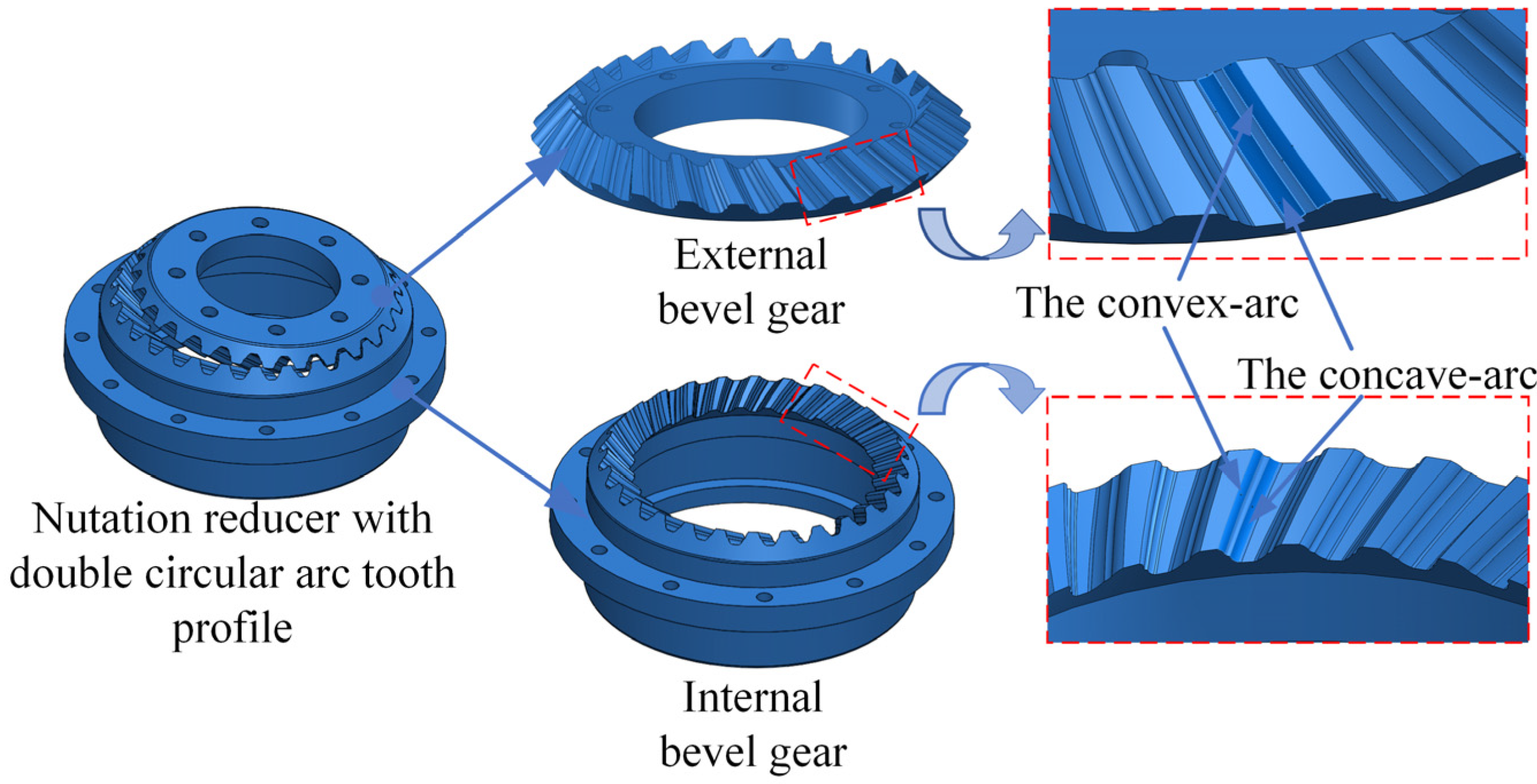
However, no specified manufacturing method can be used directly for the manufacturing of the internal spiral bevel gear. The main reason for this is that the teeth of the internal spiral bevel gear are distributed on the internal cone surface. Although it has the commonality of tooth milling, it has its own unique structure of individuality [6]. As shown in Figure 1, the bending and twisting of the bevel gear tooth surface geometry may lead to the tool cutting surface becoming embedded in the theoretical tooth surface. The material within the theoretical tooth surface will be removed; that is, the tool cutting surface on the theoretical tooth surface may produce an overcutting phenomenon. Meanwhile, the actual process of machining the parts is easy and involves cutting the completed surface again, resulting in secondary cutting, which affects the smooth processing of tooth cutting and reduces the working performance of the gear.

Figure 1.
Double-arc spiral bevel gear nutation reducer.
To solve the machining problem of the internal spiral bevel gear, special finger milling cutters were designed in this paper considering the characteristics of double-arc tooth profile. The innovativeness of the developed methodology is that the section shape of the finger milling cutter is designed as a double-arc curve in this paper. At the same time, considering the complexity of its design and manufacture, the double-arc curve is divided into four segments, and four finger milling cutters are designed to machine different arc segments. Compared with the general form milling cutter, the machining efficiency and accuracy have been greatly improved. The efficient machining method of the internal spiral bevel gear will further promote the application of a nutation reducer in a joint reducer.
2. Mathematical Modeling of the Tooth Profile with a Double-Arc Internal Spiral Bevel Gear
To solve the manufacturing problem of the internal spiral bevel gear, it is essential to establish a mathematical model of the tooth profile for the finger milling cutter design and carry out trajectory planning, manufacturing interference inspection and manufacturing simulation.
2.1. Tooth Profile Design
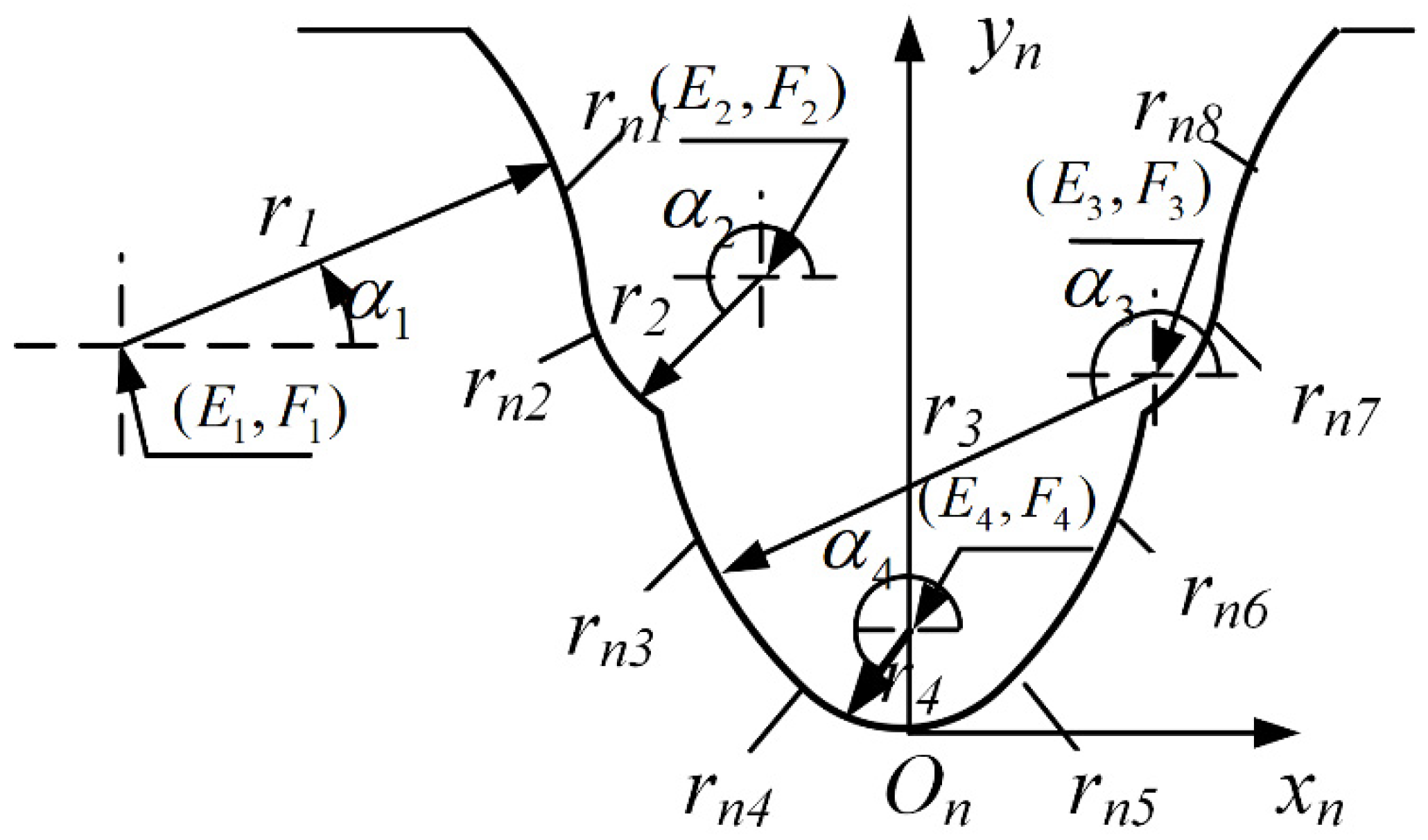
The normal tooth profile of the internal spiral bevel gear is adopted from the national standard double circular arc tooth profile (GB/T12759-1991) [5]. The basic double circular arc tooth profile is shown in Figure 2. The standard tooth profile is suitable for a double circular arc gear transmission with normal modulus = 1.5~50 mm. The tooth profile is composed of two convex arcs, two concave arcs, two transition arcs and two tooth root arcs. In the meshing process, the convex and concave arcs contact each other. Because of the two pairs of convex and concave arcs, the transmission is called a double meshing line transmission.
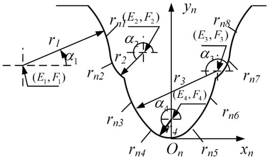
Figure 2.
Double circular arc basic tooth profile (GB/T12759-1991).
The coordinate system is established on the face balance line of the double circular arc teeth. The coordinates of any point on each circular arc can be determined by using the circular arc radius and the starting and ending positions angle of the circular arc . This is expressed by:
The tooth profile parameters of the double circular arc tooth profile can be calculated according to the GB/T12759-1991 standard. After substituting these parameters in Equation (1), eight segment double-arc standard tooth profiles with different modulus can be obtained. Table 1 shows the calculation parameters of each arc in the standard double arc basic tooth profile.

Table 1.
Calculation parameters of standard double circular arc tooth profile.
Where, is the offset of convex tooth profile center, is the offset of concave tooth profile center, is the displacement of convex tooth profile center, is the displacement of concave tooth profile center, is dedendum and is addendum. is the convex tooth process angle and is concave tooth process angle. is the convex tooth profile radius and is the concave tooth profile radius. is the transition arc radius and is the radius of the tooth root arc.
2.2. Tooth Alignment Curve Design
In Figure 3, a coordinate system is established at the center of the crown gear. The Tooth alignment curve located at the center of the left and right tooth profile is called the central tooth direction line.
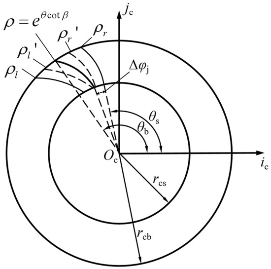
Figure 3.
Tooth alignment curve of crown gear.
The tooth alignment curve equation is given by:
In Equation (2), is the rotation angle of the tooth alignment curve meets the requirements, which is the small end rotation angle and is the large end rotation angle.
where is the helix angle at the small end of the tooth alignment curve, so , R is the internal cone distance.
To obtain the boundary curves of the left and right tooth profiles of the double circular arc tooth profile and , the tooth alignment curve is rotated to the left and right by an angle around the coordinate system.
where is the arc radius of the arc tooth profile and is the offset of the arc center.
P is the point on the boundary of the tooth profile with double arc. The boundary curve equation of the double circular arc tooth profile is established as:
To process the left and right boundaries of the tooth profile, the machining path of the cutter tip is taken as the normal isometric curve corresponding to the boundary curve. The unit normal vector is estimated with the help of the following relation:
With the help of the above relations, the equidistant curve of the boundary curve and is transformed into:
For Equations (6) to (8), the left side of the central tooth alignment curve is positive, and the right side is negative.
2.3. Tooth Alignment Curve Equation of the Internal Spiral Bevel Gear
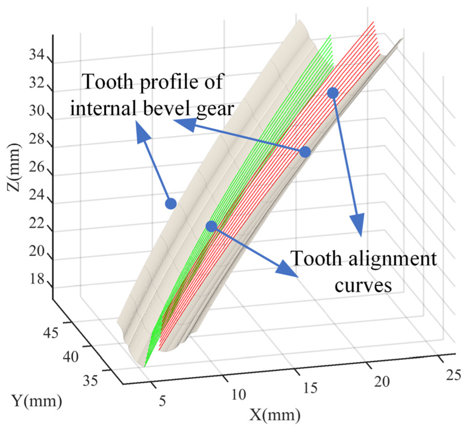
The tooth alignment curve of the internal spiral bevel gear is an important parameter to describe the tooth shape of the internal spiral bevel gear. It also tracks the motion of the finger milling cutter tip during the internal spiral bevel gear machining by the forming method. As mentioned before, it is our best understanding that until now, no research has investigated the tooth alignment curve equation of the internal spiral bevel gear. Based on the machining principle, the expression of the tooth alignment curve of the internal spiral bevel gear is derived from the tooth alignment curve equation on the crown gear coordinate system.
As shown in Figure 4, the position of the actual tooth direction line also shows the feed direction of each cutting depth tool while machining the left and right tooth profiles.
where, is the angle of the crown gear and is the angle of the internal double-arc spiral bevel gear. is the indexing angle of the internal double circular arc spiral bevel gear

Figure 4.
The actual tooth alignment curves (3D).
2.4. Mathematical Modeling Method
In the nutation reducer, the meshing motion of the internal and external double circular arc spiral bevel gears can be replaced by an imaginary crown gear. The pitch cone angle of the crown gear is 90° and the tooth depth along the pitch cone generatrix remains unchanged. The generation of the internal and external double-arc spiral bevel gears can be regarded as the envelope process of crown gear. The design and manufacturing of the internal spiral bevel gears can be based on the crown gears.
The meshing coordinate system is established according to the correlation between the crown gear and the internal meshing of the double-arc spiral bevel gear. Figure 5 shows the meshing coordinate system of the crown gear and the internal spiral bevel gear, whereas is the fixed coordinate system of the crown gear and is the motion coordinate system of the crown gear. It must be noted that the initial positions of the coordinate systems coincide. During the meshing process, the coordinate system rotates around the axis at a uniform angular speed. Here, the relative angle for the fixed coordinate system of the internal spiral bevel gear is . is the fixed coordinate system of the internal spiral bevel gear and is the motion coordinate system of the internal spiral bevel gears. During the meshing process, the coordinate system rotates uniformly around the k2 axis, and the relative angle is .
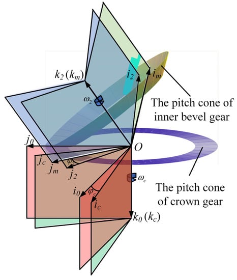
Figure 5.
Meshing coordinate system for crown gear and internal spiral bevel gear.
According to the coordinate system established by the above meshing relation, the coordinate transformation matrix of the crown gear dynamic coordinate system and internal spiral bevel gear dynamic coordinate system is obtained as:
where,
As shown in Figure 6, the coordinate system is established on the actual tooth alignment curve. The double-arc tooth profile scanned along the actual tooth alignment curve to form the tooth profile of the crown gear. The E and R change, and their change law is related to the tooth alignment curve equation. The is the included angle between the tangent passing through any point and the connecting line between the point and the origin, and the central tooth alignment curve meets when . The equidistant curves of the left and right boundary tooth profiles meet at .

Figure 6.
Coordinate relationship between tooth profile and tooth alignment curve.
The coordinate transformation matrix for the coordinate system to is expressed as:
where , , , the tooth profile equation of the crown gear is:
where is the radius of each arc of the double-arc tooth profile, corresponds to the angle of each arc, and , is the center coordinate of the arc, i = 1, 2, ..., 8.
Equation (13) is the tooth surface equation of the internal spiral bevel gear through the coordinate transformation of Equation (10):
The tooth profiles drawn by the derived tooth profile Equation (12) and Equation (13) are shown in Figure 7.

Figure 7.
Double-arc tooth profiles: (a) The tooth profile of a crown gear. (b) The tooth profile of internal spiral bevel gear.
3. The Design of the Finger Milling Cutter
The tooth profile equation derived in the previous section considers 8 arcs in the tooth profile of internal double-arc spiral bevel gear. Due to the complexity of the double-arc tooth profile, special finger milling cutters for machining internal double-arc spiral bevel gear are designed.
3.1. Solving the Tool Rotation Surface with the Known Tooth Profile Equation
As shown in Figure 8, the machining coordinate system is established with the tangent vector, main normal vector and auxiliary normal vector of the path curve as the coordinate axis. A contact curve exists with the movement of the finger milling cutter, the shape of which is also the axial section of the finger milling cutter.

Figure 8.
Coordinate system for tool section solution.
During the processing of the finger milling cutter, the contact curve shall meet the following requirements:
where, K is the unit vector of the main normal vector; R is the radial vector that is obtained from the origin of the tool coordinate system to the point M on the tooth profile surface, and n is the normal vector of M on the tooth profile surface. Geometrically, this expression means that the radial vector R, normal vector n, and the unit vector K are collinear.
We simplify the solution method to the crown gear. The above equation of crown gear tooth surface is expressed as:
According to the above established coordinate system, the expression of K and R in the internal spiral bevel gear coordinate system is obtained as:
Then:
Therefore, the conditional formula of the contact line becomes:
Then, the normal vector n at any point M of the surface is:
where,
The unit vector is given by:
By substituting the obtained contact line condition formula into the tooth surface equation of the crown gear, the rotating surface can be obtained as:
The equation of the tool can be obtained by converting to the tooth coordinate system:
The tool revolution surface equation obtained above is consistent with the standard tooth profile equation. This shows that the double circular arc tooth profile can be taken as the rotating surface of the selected cutter to design the milling cutter.
3.2. The Designing of Finger Milling Cutter
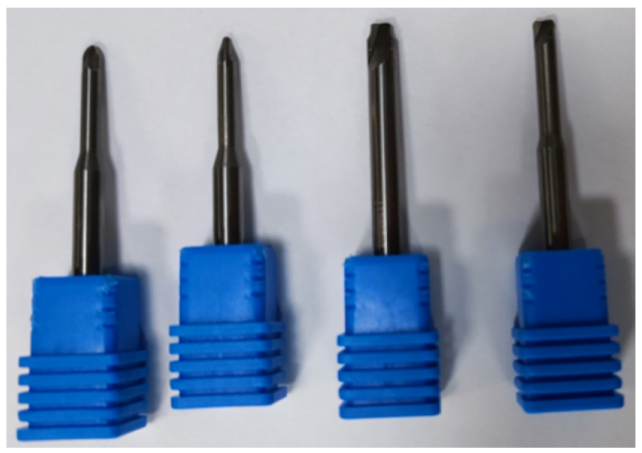
In this paper, considering that the design of the finger milling cutter with double-arc tooth profile is complex, it is resolved into four finger milling cutters. There are, respectively, used to machine the convex tooth surface, concave tooth surface, transitional tooth surface and tooth root surface, as shown in Figure 9.

Figure 9.
The resolution of the finger milling cutter.
The tool used for the real machining process is shown in Figure 10. The material of the tool is cemented carbide and the front angle is 5° and the rear angle is 15°, open at the double edge.

Figure 10.
Tools for actual machining.
The finger milling cutters were created by a company called Walter. The machining method proposed in this paper can effectively solve the machining problem of the internal double-arc spiral bevel gear. The change in modulus will lead to the change in double arc size. At this time, the tool can no longer meet the milling conditions and needs to be redesigned. This will result in an increase in machining costs. The commonly used modulus needs to be considered in the actual machining process. In order to ensure the practical application of this method in industrial practice, it is important to focus on machining the internal double-spiral bevel gears with limited modules, so that it can bring economic and social benefits.
4. Simulation and Verification of the Tooth Surface of the Internal Spiral Bevel Gear
The last section completed the design of the finger milling cutters. This section simulates and verifies the actual condition of machining the internal spiral bevel gear with a set of designed finger milling cutters. At the same time, the size of machining error is estimated. The actual machining processing on the machine tool was also carried out. Lastly, measuring the error of the finished gear and verifying the feasibility and superiority of this method was carried out.
4.1. Determination of Machining Parameters
The internal spiral bevel gear in the prototype is machined in this paper, and its parameters are shown in Table 2:
Table 2.
Parameters of the spiral bevel gear.
4.2. Simulation Machining Process of the Internal Spiral Bevel Gear
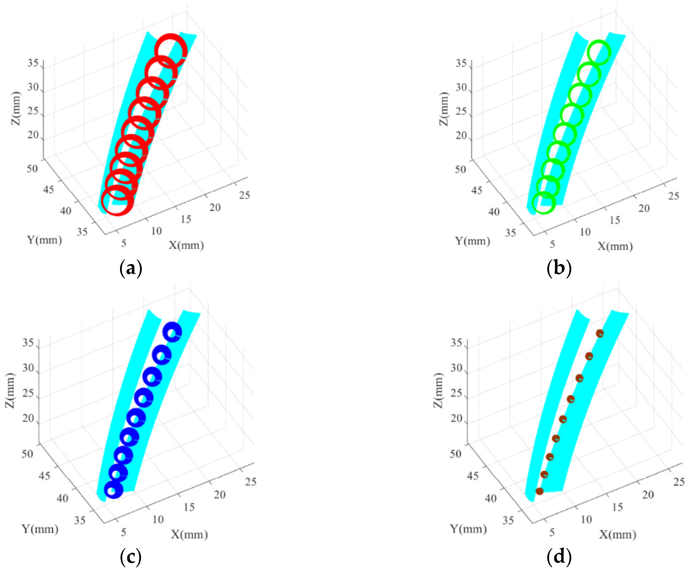
The finger milling cutter models designed in the previous section were imported into the tool system of SolidCam. Preliminary machining was completed with a flat bottom cutter. The purpose was to reserve machining allowance for subsequent machining, as shown in Figure 11. Figure 11a shows the machining of the convex tooth surface and rough machining of the transitional tooth surface; Figure 11b further shows the machining of the transitional tooth surface. Figure 11c shows the machining of the concave tooth surface, and also the final preliminary machining of the tooth root tooth surface; and Figure 11d shows the finished machining of the tooth root surface on this basis.
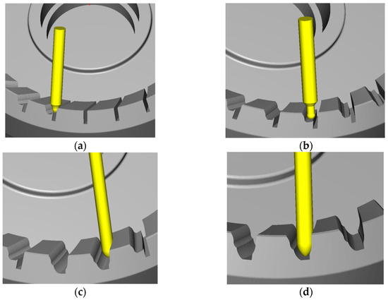
Figure 11.
Simulation machining experiment with SolidCam: (a) Machining the convex tooth surface; (b) Machining the transition tooth surface; (c) Machining the concave tooth surface; (d) Machining the root tooth surface.
4.3. Machining Interference Inspection
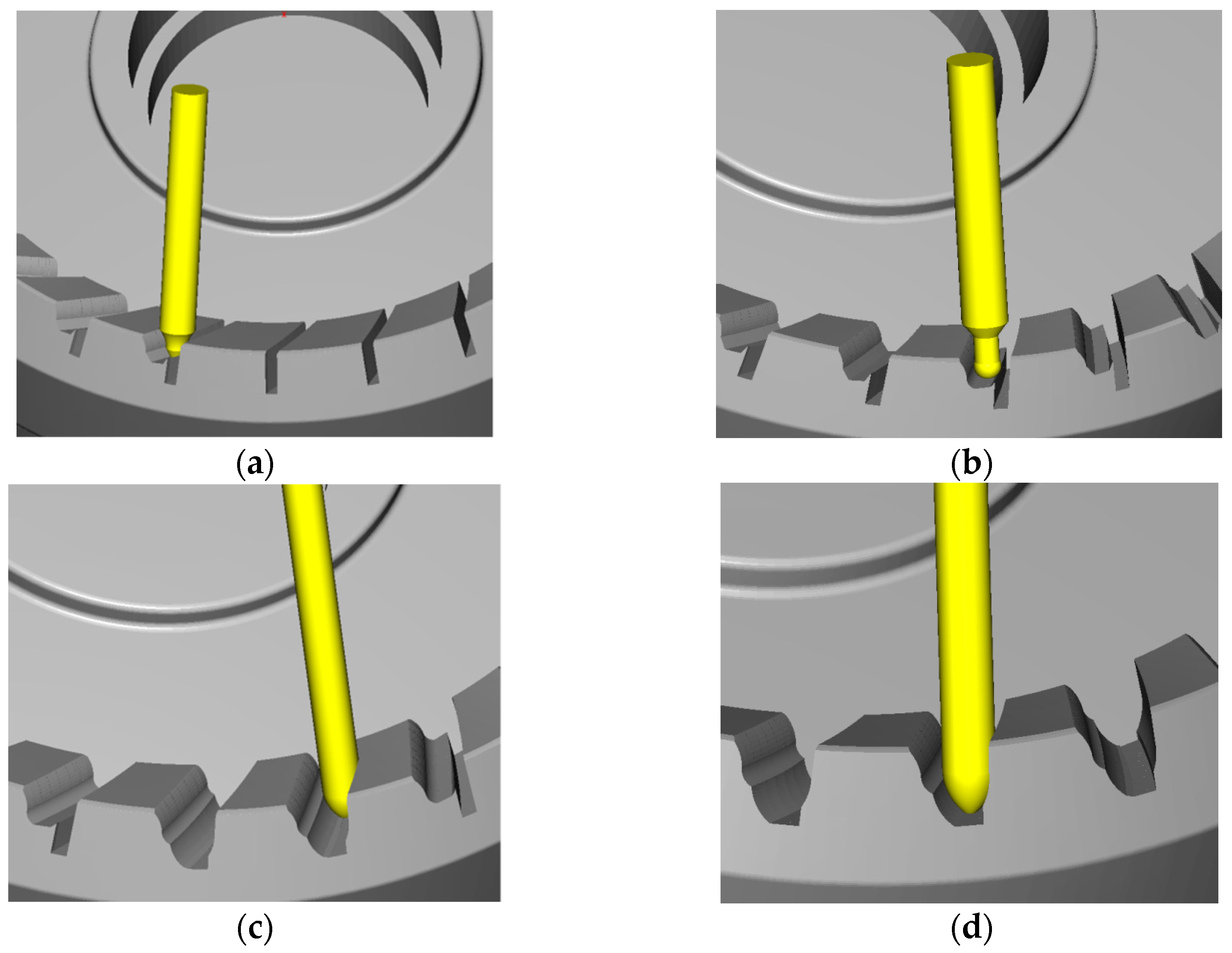
To simulate the cutting process of each finger milling cutter through programming, and judge whether there is cutting interference at the same time, Figure 12 shows the simulated machining process of each finger milling cutter.
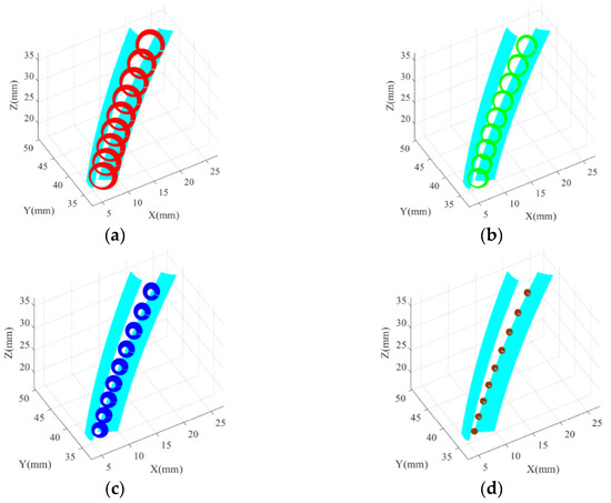
Figure 12.
Machining simulation: (a) Machining the convex tooth surface; (b) Machining the transition tooth surface; (c) Machining the concave tooth surface; (d) Machining the root tooth surface.
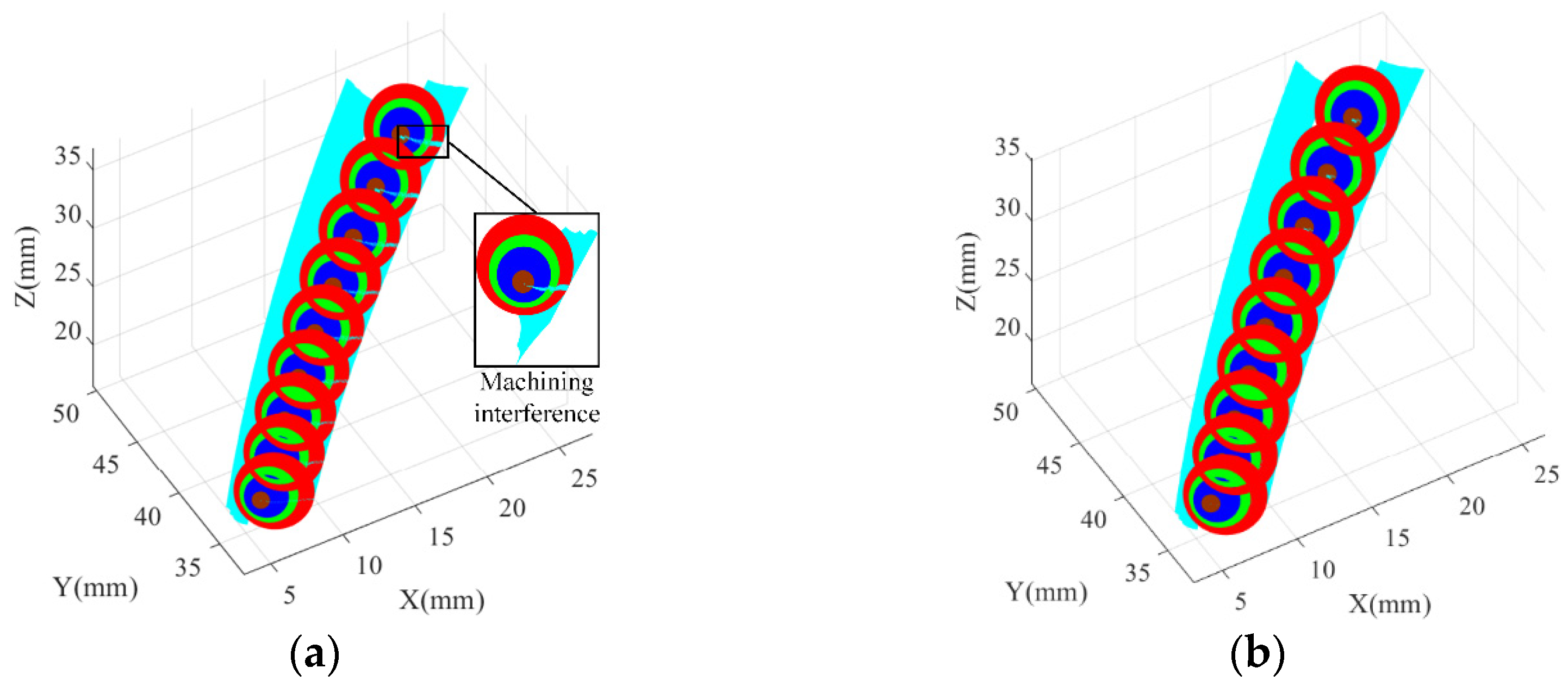
Figure 13a shows the simulated machining process of one finger milling cutter with a double-arc, in which exists machining interference. With the continuous feeding of the finger milling cutter from the small end to the large end, the overlapping part of the finger milling cutter and the tooth profile also gradually increases. This means that the machining interference is gradually increases. This is related to the spiral angle of the tool path curve, but the error is very small.

Figure 13.
Machining process of finger milling cutter with double-arc: (a) Machining without error compensation; (b) Machining with error compensation.
Appling the method of error compensation to calculate the machining error, Figure 13b shows the position relationship between the milling cutter and the tooth surface after error compensation. Compared with Figure 13a, there is no overlapping part, which means no machining interference. The tooth surface in Figure 13b is also the actual machined tooth surface. Among them, the error compensation of the convex tooth surface is the smallest, which is 0.005 mm. The error of the concave tooth surface and the transitional tooth surface is 0.030 mm, and the error of the tooth root surface is 0.032 mm.
4.4. Real Machining Process of the Internal Spiral Bevel Gear
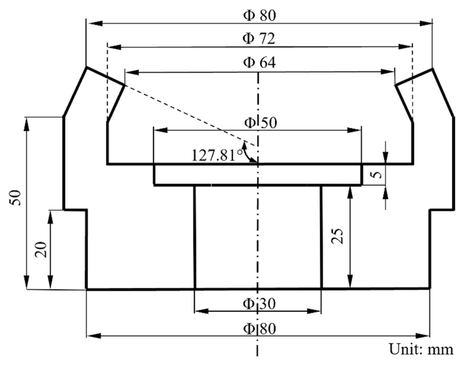
The workpiece material is aluminum. The specific sizes are shown in Figure 14. The cutting speed is 3000 rpm, and the feed rate is 40 mm/min.
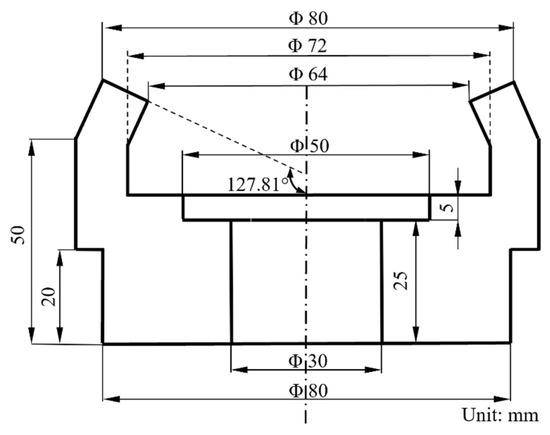
Figure 14.
Detailed data about the workpiece.
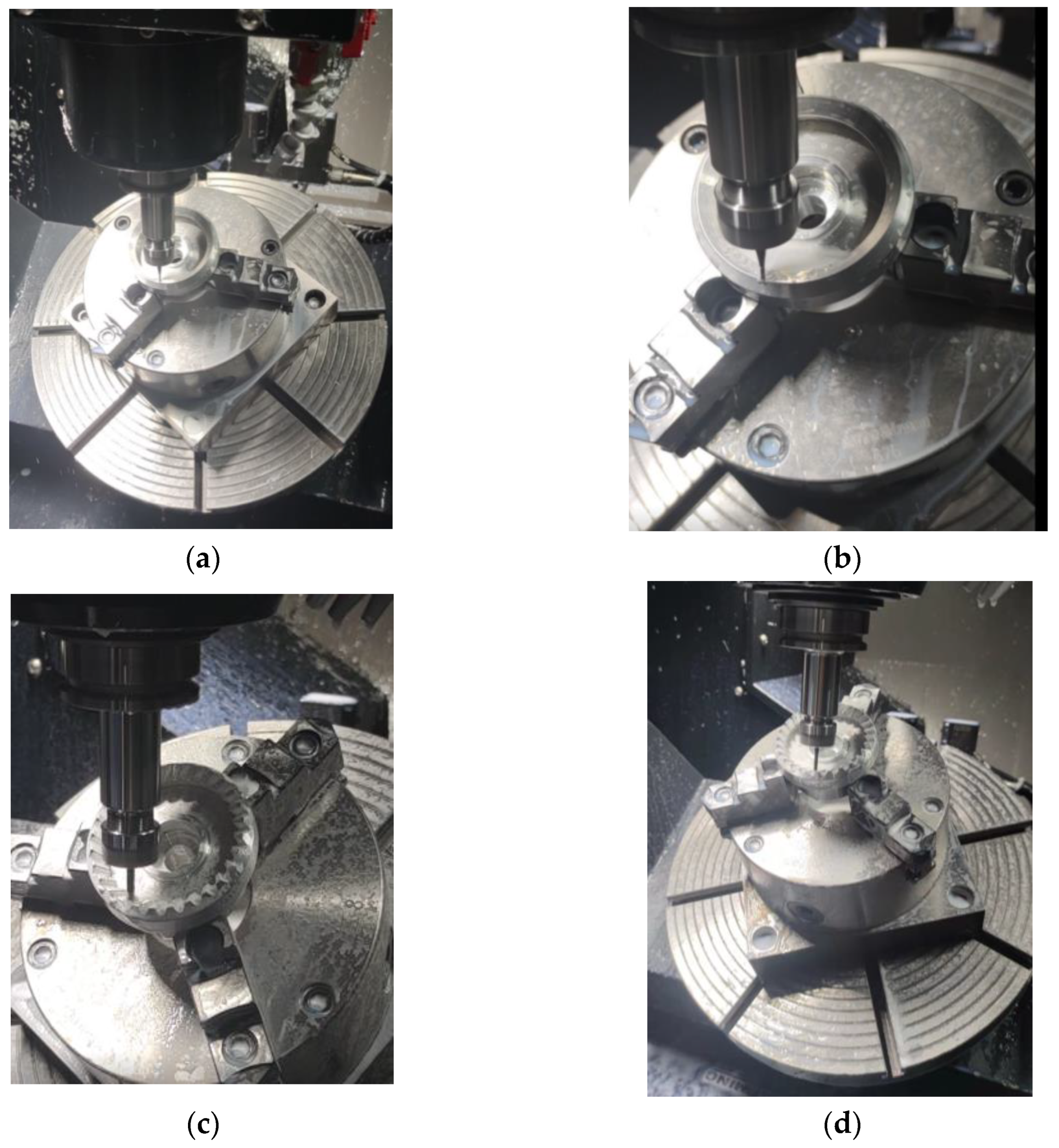
In order to verify the simulation results, the five-axis machine tool GMU-400 was used for actual machining, as shown in Figure 15. At the same time, the tooth surface of the machined internal spiral bevel gear was tested and compared with the simulation results.
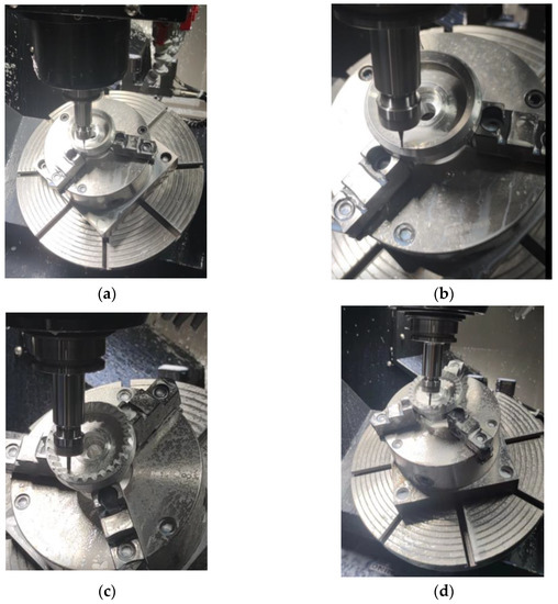

Figure 15.
Actual machining process: (a) Fixing of the blank and tool setting; (b) Preliminary machining with a flat bottom cutter; (c) Machining the convex tooth surface; (d) Machining the transition tooth surface; (e) Machining the concave tooth surface; (f) Machining the root tooth surface.
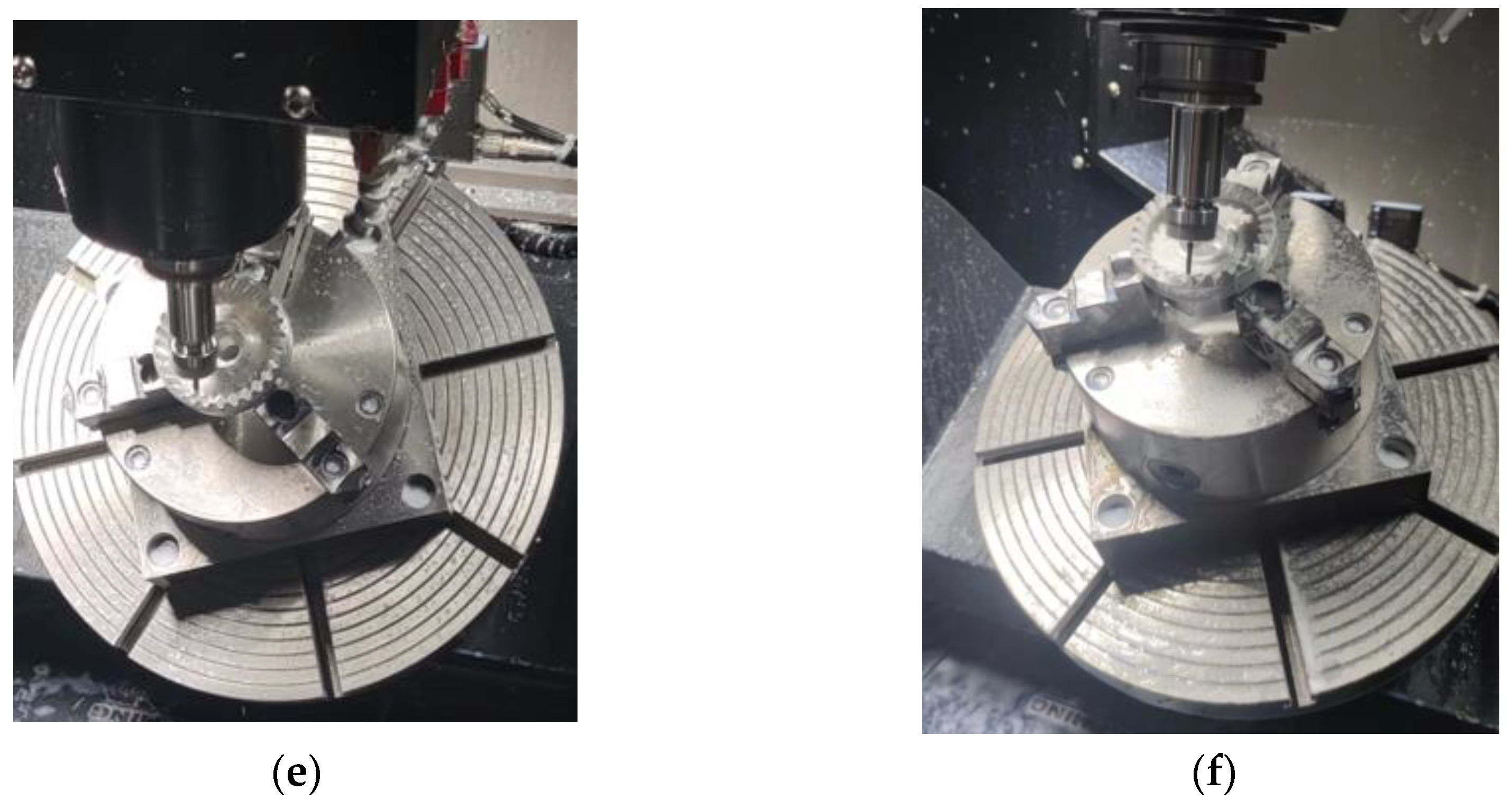
The points to be tested were randomly selected on the same tooth side surface of the internal spiral bevel gear. A total of 26 sample points were randomly collected for the error testing.
The measuring device is a Hexagon Pioneer 3-CMM. Angle beam design, aluminum alloy material technology and integral granite platform improve the accuracy of measurement and stability of operation. Equipped with global PC-DMIS measurement software and various triggering and scanning detection systems, the device is suitable for general measurement requirements and can complete the measurement and quality control tasks of various workpieces.
The specific detection process is as follows. Moving the probe to the measured point, the probe contacts the workpiece and sends a point acquisition signal. The control system collects the coordinate value of the current three-axis coordinate of the machine tool. Then, the computer system processes the data, and the digital display device displays the coordinates. The measurement accuracy is 0.001 mm, and the measurement uncertainty is 0.021 mm.
The specific distribution is shown in Figure 16. The measured coordinates are then compared with the theoretical coordinates to obtain the errors in each direction and the total error is calculated. The specific results are shown in Table 3.
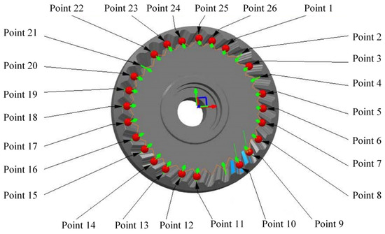
Figure 16.
The distribution of sample points.
Table 3.
Date of the error of each direction.
As shown in Figure 17, the error of each measured point can be analyzed more clearly. It can be seen that the maximum error is 0.035 mm, and the minimum error is 0.003 mm. Average error is less than 0.02 mm. It is obvious that the error in the Z-direction has the greatest impact on the accuracy of the internal bevel gear from the figure. The reason is that the vertical high-speed machining center is selected. The overlapping of vibration frequencies in machining will cause resonance. The vibration of the machine tool will cause the tool to vibrate up and down. The pitch cone angle of the machined internal double-arc spiral bevel gear is 127.81°. The error of the internal double-arc spiral bevel gear in the Z-direction will be larger than any other directions during machining. Bearing wear will also lead to tool vibration, which will result in machining errors.
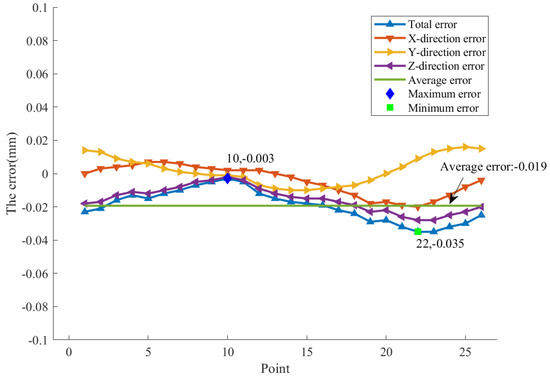
Figure 17.
The error distribution of sample points.
The manufacturing error and uneven wear of guide rail are important factors of machine tool error. The manufacturing and assembly errors of the transmission chain will cause the position offset between the tool and the workpiece. The thermal error of the machine tool has the greatest influence on machining accuracy. In addition to the heat of the equipment, it is mainly concentrated in the cutting part, which will lead to the deformation of tools and workpieces. The force generated in the cutting process will also deform the tool and workpiece. The dimensional errors of tools and workpieces in the manufacturing process will reduce the machining accuracy and increase the surface roughness. At the same time, due to the small size of the tool, it is not easy to clamp. Sliding may occur under the action of force.
The machining accuracy can be raised by improving the machining condition in the Z-direction, such as ensuring the lubrication conditions of bearings to reduce bearing wear, finding the parts that produce resonance and change the frequency to avoid resonance, measuring the original error in the Z-direction of the machine tool with the laser interferometer and considering the original error in the process of NC programming.
The result is consistent with the simulation results, which verifies the feasibility of machining the internal double-arc spiral bevel gear with a group of finger milling cutters.
There is limited research by scholars on the machining of the internal double-arc spiral bevel gears. Other similar studies focus on the machining of the external spiral bevel gears. Comparing the results with other similar studies, this paper analyzes not only the overall error but also the errors in all directions. The method proposed in this paper can ensure the machining quality; however, special tools need to be customized. The processing cost and efficiency are inferior to other similar studies.
5. Conclusions
We provide a method for machining the internal double-arc spiral bevel gears. This method can effectively solve the machining problem of the internal spiral bevel gears. It provides a successful case for the machining of complex surfaces.
- (1)
- Aiming at the proposed method of machining the internal double-arc spiral bevel gear with a finger milling cutter, the intercept equation of the finger milling cutter is solved. Considering the processing difficulty, it is divided into four finger milling cutters, which are used to process the convex tooth surface, transitional tooth surface, concave tooth surface and tooth root surface, respectively.
- (2)
- A simulation machining experiment with the designed finger milling cutter was carried out. Compared with the ideal tooth surface, the error of the convex tooth surface is the smallest, which is 0.005 mm. The error of the concave tooth surface and transitional tooth surface is 0.030 mm, and the error of the tooth root surface is 0.032 mm. The 26 sample points on the machined gear were measured. The maximum error was 0.035 mm, the minimum error was 0.003 mm, and the average error was 0.019 mm, meeting the machining requirements. The Z-direction error has the greatest influence on the overall error.
- (3)
- This method requires the design and manufacture of special milling cutters, which increases the machining cost. The size of the tool is small, and it is easily deformed under stress and heat during machining. At the same time, many tool changes are required in the machining process, which result in the low efficiency of small batch production.
- (4)
- This method does not consider the heat and force generated in the processing process. Subsequent research can reduce the machining error and improve the machining accuracy by analyzing the coupling of the stress field and temperature field. Meanwhile, the tool structure can be optimized to improve the tool life and machining accuracy.
Author Contributions
Conceptualization, L.Y.; methodology, D.Z.; software, D.X.; validation, Z.W. and D.X.; formal analysis, D.Z.; investigation, Z.W.; resources, L.Y.; data curation, D.X.; writing original draft preparation, D.Z.; writing—review and editing, L.Y.; visualization, Z.W.; supervision, Z.W.; project administration, D.Z.; funding acquisition, L.Y. All authors have read and agreed to the published version of the manuscript.
Funding
This work was supported in part by the National Natural Science Foundation of China, Grant No. 51775114; the Fujian Provincial Science and Technology Major Special Project, Grant No. 2021HZ024006; and the Fujian Provincial High-End Equipment Manufacturing Collaborative Innovation Center, Grant No. 2021-C-275.
Institutional Review Board Statement
Not applicable.
Informed Consent Statement
Not applicable.
Data Availability Statement
Not applicable.
Acknowledgments
The authors would like to thank Chengdu Jingyuan Technology Co., Ltd. for the hard finishing and measuring of the internal double-arc spiral bevel gear.
Conflicts of Interest
The authors declare that they have no known competing financial interests or personal relationships that could have appeared to influence the work reported in this paper.
References
- Cai, Y.W.; Yao, L.G.; Zhang, J.; Xie, Z.Y.; Hong, J.L. Feasibility analysis of using a two-stage nutation drive as joint reducer for industrial robots. J. Mech. Sci. Technol. 2019, 33, 1799–1807. [Google Scholar] [CrossRef]
- Saribay, Z.B.; Bill, R.C. Design analysis of pericyclic mechanical transmission system. Mech. Mach. Theory 2013, 61, 102–122. [Google Scholar] [CrossRef]
- Uzuka, K.; Enomoto, I.; Suzumori, K. Comparative assessment of several nutation motor types. IEEE ASME Trans. Mechatron. 2009, 14, 82–92. [Google Scholar] [CrossRef]
- Mlendini, P.; Perrone, M.; Stam, S.; Barbagelate, A.; Primavori, M.; Appolonia, S.D. Wobbling gears achieve high ratios. ESA J. 2010, 10, 34–37. [Google Scholar]
- Yao, L.G.; Gu, B.; Huang, S.J.; Wu, W.G.; Dai, J.S. Mathematical modeling and simulation of the external and internal double circular-arc spiral bevel gears for the nutation drive. ASME J. Mech. Des. 2010, 132, 8–13. [Google Scholar] [CrossRef]
- Lin, Z.; Yao, L.G.; Zhang, J.; Su, T.K.; Chen, K.J. Tooth contact analysis with latent error of double circular-arc spiral bevel gears for industrial robot joint nutation drive. J. Braz. Soc. Mech. Sci. Eng. 2020, 42, 10. [Google Scholar] [CrossRef]
- Su, Y.J.; Yao, L.G.; Zhang, J. Contact dynamics analysis of nutation drive with double circular-arc spiral bevel gear based on mathematical modeling and numerical simulation. Mech. Sci. 2021, 12, 185–192. [Google Scholar] [CrossRef]
- Lou, M.Y.; Yao, L.G.; Zheng, Y.S. Numerical analysis on magnetic field and torque of a disk-type nutation magnetic drive. IEEE Trans. Magn. 2020, 56, 4900106. [Google Scholar] [CrossRef]
- Habibi, M.; Chen, Z.C. A semi-analytical approach to un-deformed chip boundary theory and cutting force prediction in face-hobbing of bevel gears. Comput. Aided Des. 2016, 73, 63–65. [Google Scholar] [CrossRef]
- Efstathiou, C.; Tapoglou, N. A novel CAD-based simulation model for manufacturing of spiral bevel gears by face milling. CIRP J. Manuf. Sci. Technol. 2021, 33, 277–292. [Google Scholar] [CrossRef]
- Wang, S.H.; Zhou, Y.S.; Liu, X.R.; Liu, S.J.; Tang, J.Y. An advanced comprehensive approach to accurately modeling the face-milled generated spiral bevel gears. J. Comput. Inf. Sci. Eng. 2021, 21, 041008. [Google Scholar] [CrossRef]
- Zhou, Y.S.; Chen, Z.Z.C.; Tang, J.Y. A new method of designing the tooth surfaces of spiral bevel gears with ruled surface for their accurate five-axis flank milling. ASME J. Manuf. Sci. Eng. 2017, 139, 061004. [Google Scholar] [CrossRef]
- Zheng, F.; Hua, L.; Chen, D.; Han, X. Generation of noncircular spiral bevel gears by face-milling method. ASME J. Manuf. Sci. Eng. 2016, 138, 081013. [Google Scholar] [CrossRef]
- Zheng, F.; Hua, L.; Han, X.; Chen, D.F. Generation of non-circular bevel gears with free-form tooth profile and tooth lengthwise based on screw theory. ASME J. Mech. Des. 2016, 138, 064501. [Google Scholar] [CrossRef]
- Li, G.L.; Du, S.C.; Wang, B.; Lv, J.; Deng, Y.F. High definition metrology-based quality improvement of surface texture in face milling of workpieces with discontinuous surfaces. ASME J. Manuf. Sci. Eng. 2022, 144, 031001. [Google Scholar] [CrossRef]
- Li, G.L.; Du, S.C.; Huang, D.L.; Zhao, C.; Deng, Y.F. Dynamics modeling-based optimization of process parameters in face milling of workpieces with discontinuous surfaces. ASME J. Manuf. Sci. Eng. 2019, 141, 101009. [Google Scholar] [CrossRef]
- Shih, Y.; Zhang, C. Manufacture of spiral bevel gears using standard profile angle blade cutters on a five-axis computer numerical control machine. ASME J. Mech. Des. 2017, 139, 061017. [Google Scholar] [CrossRef]
- Bo, P.; González, H.; Calleja, A.; Lacalle, L.; Bartoň, M. 5-axis double-flank CNC machining of spiral bevel gears via custom-shaped milling tools—Part I: Modeling and simulation. Precis. Eng.-J. Int. Soc. Precis. Eng. Nanotechnol. 2020, 62, 204–212. [Google Scholar] [CrossRef] [Green Version]
- Jiang, J.F.; Luo, Q.S.; Wang, L.T.; Qiao, L.J.; Li, M.H. Review on logarithmic spiral bevel gear. J. Braz. Soc. Mech. Sci. Eng. 2020, 42, 400. [Google Scholar] [CrossRef]
- Hoai, N.H.; Yusuf, A. Modeling the dynamics of five-axis machine tool using the multibody approach. ASME J. Manuf. Sci. Eng. 2021, 143, 021012. [Google Scholar]
- Sun, H.; Zou, B.; Chen, W. Cutting performance of silicon-based ceramic end milling tools in high-efficiency machining of GH4099 under dry condition. Int. J. Adv. Manuf. Technol. 2021, 118, 1719–1732. [Google Scholar] [CrossRef]
- Perez, I.G.; Aznar, A.F. Reverse engineering of spiral bevel gear drives reconstructed from point clouds. Mech. Mach. Theory 2022, 170, 104694. [Google Scholar] [CrossRef]
- Perez, I.G.; Saura, P.L.; Aznar, A.F. Application of the bilateral filter for the reconstruction of spiral bevel gear tooth surfaces from point clouds. ASME J. Mech. Des. 2021, 143, 053401. [Google Scholar] [CrossRef]
- Álvarez, A.; Lacalle, L.; Olaiz, A. Large spiral bevel gears on universal 5-axis milling machines: A complete process. Manuf. Eng. Soc. Int. Conf. 2015, 132, 397–404. [Google Scholar] [CrossRef] [Green Version]
- Rong, K.; Ding, H.; Tang, J. Adaptive data-driven modular control approach to computer aided process planning for manufacturing spiral bevel and hypoid gears. Proc. Inst. Mech. Eng. Part B J. Eng. Manuf. 2021, 235, 514–532. [Google Scholar] [CrossRef]
- Gonzalez, I.; Fuentes, A. Conjugated action and methods for crowning in face-hobbed spiral bevel and hypoid gear drives through the spiral system. Mech. Mach. Theory 2019, 139, 109–130. [Google Scholar] [CrossRef]
- Celikag, H.; Ozturk, E.; Sims, N. Can mode coupling chatter happen in milling? Int. J. Mach. Tools Manuf. 2021, 165, 103738. [Google Scholar] [CrossRef]
- Tajima, S.; Sencer, B. Online interpolation of 5-axis machining toolpaths with global blending. Int. J. Mach. Tools Manuf. 2022, 175, 103862. [Google Scholar] [CrossRef]
- Franco, O.; Beudaert, X.; Iglesias, A.; Dombovari, Z.; Erkorkmaz, K.; Munoa, J. Optimal cutting condition selection for high quality receptance measurements by sweep milling force excitation. Int. J. Mach. Tools Manuf. 2022, 176, 103873. [Google Scholar] [CrossRef]
- Tehranizadeh, F.; Berenji, K.R.; Budak, E. Dynamics and chatter stability of crest-cut end mills. Int. J. Mach. Tools Manuf. 2021, 171, 103813. [Google Scholar] [CrossRef]


Publisher’s Note: MDPI stays neutral with regard to jurisdictional claims in published maps and institutional affiliations. |
© 2022 by the authors. Licensee MDPI, Basel, Switzerland. This article is an open access article distributed under the terms and conditions of the Creative Commons Attribution (CC BY) license (https://creativecommons.org/licenses/by/4.0/).