Review

Tracked Locomotion Systems for Ground Mobile Robots: A Review

Department of Mechanical, Energy, Management and Transportation Engineering, University of Genoa, 16145 Genoa, Italy
*
Author to whom correspondence should be addressed.
Machines 2022, 10(8), 648; https://doi.org/10.3390/machines10080648
Submission received: 30 June 2022 / Revised: 27 July 2022 / Accepted: 28 July 2022 / Published: 4 August 2022
(This article belongs to the Special Issue Feature Review Papers on Automation Systems)

Abstract

:
The paper discusses the state-of-the-art of locomotion systems for ground mobile robots comprising tracks. Tracked locomotion, due to the large contact surface with the ground, is particularly suitable for tackling soft, yielding, and irregular terrains, but is characterized by lower speed and energy efficiency than wheeled locomotion, and lower obstacle-climbing capability than legged locomotion. Therefore, in recent years academic and industrial researchers have designed a wide variety of hybrid solutions, combining tracks with legs and wheels. The paper proposes three possible parallel taxonomies, based on body architecture, track profile, and track type, to help designers select the most suitable architecture on the basis of the operative necessities. Moreover, modeling, simulation, and design methodologies for tracked ground mobile robots are recalled.

1. Introduction

Service robotics is presently one of the fastest-growing technological fields [1]. Nevertheless, while Automated Guided Vehicles (AGV) moving on flat and compact grounds are already commercially available and widely used to move components and products inside industrial buildings, the extensive application of ground mobile robots in environments that are unstructured or structured for humans is a promising challenge for the next years [2]. The important application fields are agriculture [3,4], planetary exploration [5,6], reconnaissance in dangerous situations, such as radioactive or chemical contamination [7], homeland security and military operations [8], demining [9], intervention in case of terrorist attacks [10], and surveillance [11].
The design of a ground mobile robot is highly multidisciplinary since it involves the fields of locomotion, perception, cognition, and navigation [12]. Focusing on the mechanical aspect, ground mobile robots, excluding special-purpose ones for specific environments and surfaces (e.g., slithering, or adhesive robots) can have wheeled (W), legged (L), or tracked (T) locomotion, or hybrid combinations of these principles (LW, LT, WT, LWT). A systematic comparison of these locomotion systems is outlined in [13], in terms of maximum speed, obstacle-crossing capability, step/stair climbing capability, slope climbing capability, walking capability on soft terrains, walking capability on uneven terrains, energetic efficiency, mechanical complexity, control complexity, and technology readiness.
Another work dealing with the classification of mobile robots is [14], in which not only locomotion is considered, but also perception, cognition, control, and navigation. A classification based on structural and kinematic properties is presented in [15], although limited to wheeled robots. In [16], specific chapters are focused on locomotion architectures, in particular of wheeled robots, snake-like and continuum robots, and limbed systems (with body, legs, and arms), while other chapters of the same book discuss all aspects of mobile robotics: sensing and estimation, localization and mapping, motion planning, modelling and control of legged and wheeled robots, and of multiple robot systems. A work focused mainly on the mechanics of legged robots is [17], while [18] is more centered on control, vision, and navigation techniques. Reviews of path-planning strategies and control architectures for navigation of mobile robots are presented in [19,20,21].
In the rest of the paper, the investigation will be limited to the mechanical aspects. With regard to these, in a nutshell, wheeled robots maximize speed and energetic efficiency, while legged robots have superior mobility in unstructured environments; tracked robots are somewhere in the middle, and are particularly suitable for moving on soft and yielding terrains, thanks to the large contact area with the ground. A very synthetic and qualitative outline of the locomotion systems’ features is represented in the chart of Figure 1 [13], where the vertical axis represents the mobility in unstructured environments, and the horizontal axis represents speed and energetic efficiency. Indicatively, L, T, and W systems are diagonally placed in the graph, with mobility in unstructured environments inversely proportional to speed and energetic efficiency, while hybrid combinations aim at filling the right upper zone, with a combination of the benefits, although limited by the increase of mechanical complexity that usually implies performance compromises.
In the present paper, in contrast to [13], only locomotion systems involving tracks are considered (T, LT, WT, LWT), to provide more specific indications and hints in the conception of systems capable of efficient mobility on irregular, soft, and yielding terrains.
It should be pointed out that there is a vast amount of scientific literature concerning tracked mobile robots, which cannot be exhaustively quoted or included in the references for reasons of space. Selected works cited here were chosen to synthetically represent and compare the main locomotion system architectures involving tracks proposed in the research and industrial scenarios.

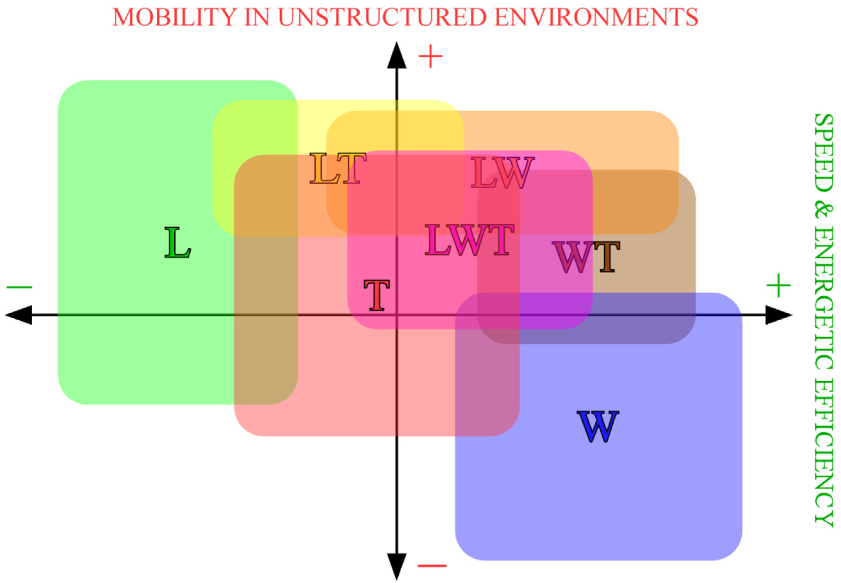
2. Classifications of Tracked Locomotion Systems

Tracked locomotion systems can be classified in many different ways. Considering the functional features, the most evident classifications can be based on:
  • Body architecture: non-articulated/articulated, type of articulation (Section 3);
  • Track profile: constant profile, passively or actively deformable profile (Section 4);
  • Track type: continuous, mechanical, and omni-tracks (Section 5).
In principle, these classifications are independent, and it is possible to associate any type of body with any type of track. This suggests using different taxonomies in parallel instead of a single taxonomy with one root node. Nevertheless, analyzing the state-of-the-art of tracked robots, it is possible to observe that more complex bodies are usually associated with simpler tracks, while more complex tracks are associated with simpler bodies, since the operative flexibility is generally obtained by only one design aspect, to avoid excessive mechanical complexity.

3. Classification of Body Architectures of Tracked Robots

3.1. Body of a Tracked Robot: Definition and Classes

In the following, the body of a tracked ground mobile robot (TGMR) will be considered as the set of all its mechanical parts, excluding the tracks, the rotating members which support the tracks (sprockets, idler sprockets, and carriers), the wheels, if present, and other internal mechanisms hosted in the robot’s main body, such as the rotating members of actuators, gearboxes, and translating devices which shift the position of some components. TGMRs can have a non-articulated body (TGMRs-NA) or an articulated body (TGMRs-A) (Figure 2).

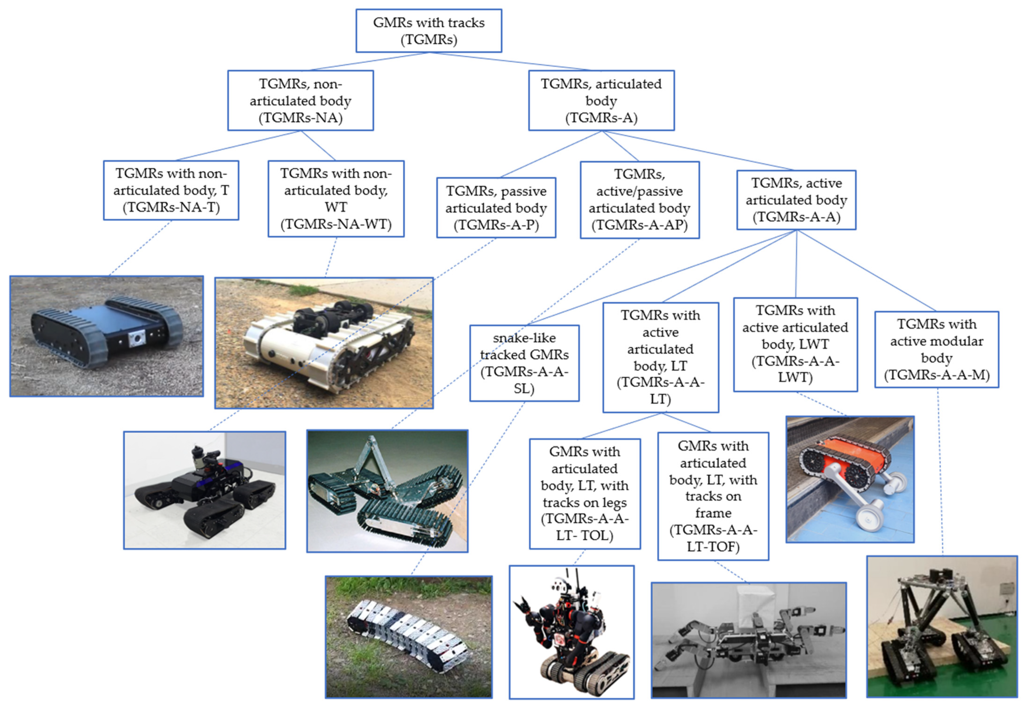
3.2. Ground Mobile Robots with Tracks, Non-Articulated Body

The category of TGMRs-NA is very widespread. Many small-scale TGMRs equipped with two tracks performing differential steering are available on the market for surveillance and inspection tasks; an example is the Trackbot by Inspectorbots ([22], the TGMR-NA-T in Figure 2). The benefits of this architecture are its extreme mechanical simplicity, and the consequent reliability and ease of control. Moreover, if the robot is symmetric with the tracks thicker than the robot body (as for the Trackbot), and has no payload mounted externally, it can operate even after a capsize. The main limitation of TGMRs-NA is their limited capability of overcoming high obstacles, steps, and stairs: to start the climbing maneuver, the height of the obstacle at the initial contact point must be lower than the track radius, even if this condition is not strictly mandatory, depending on the friction conditions and on the position of the robot’s center of gravity. Therefore, some researchers have proposed an internal mechanism to shift the longitudinal position of the robot’s center of gravity, improving the step climbing capabilities [23] (Dyjob robot, Figure 3); the obvious drawback is the weight increase and the reduction of the internal room for hosting the payload.
The TGMRs-NA scheme can be modified with the addition of retractable wheels, giving rise to hybrid wheel-track architectures (TGRMs-NA-WT), capable of faster wheeled locomotion whenever tracks are not required. An example is the TGMR-NA-WT in Figure 2 [24]; this symmetric robot can switch locomotion mode by extracting four wheels on both sides of its body thanks to an actuated slider, achieving full operativity after a capsize and maximum maneuverability, with yaw axis mobility, on flat and compact grounds.

3.3. Ground Mobile Robots with Tracks, Articulated Body

With regard to tracked robots with articulated body (TGMRs-A), we can distinguish among:
  • TGMRs with passive articulated body (TGMRs-A-P), in which all the degrees of freedom of the body are passive;
  • TGMRS with active/passive articulated body (TGMRs-A-AP), in which some degrees of freedom of the body are actuated while other are passive;
  • TGMRS with active articulated body (TGMRs-A-A), in which all the degrees of freedom of the body are actuated.
The TQTMR (Tiltable Quad-Tracked Mobile Robot) is an example of TGMR-A-P ([25], the TGMR-A-P in Figure 2); this robot consists of four driving tracks, connected to two rocker links by two-degrees-of-freedom (pitch-roll) passive joints. Such a configuration is effective in terms of traction, maneuverability, and adaptability to terrain unevenness, while maintaining low control complexity.
An example of a TGMRs-A-AP is Gunryu ([26], the TGMR-A-AP in Figure 2), characterized by two tracked modules connected by an arm mechanism. The arm mechanism is composed of two links connected by a revolute joint with elastic return force, and joined to the two tracked modules respectively by one spherical and one universal joint, for a total of six passive degrees of freedom between the two module bodies. Moreover, the two tracks of each module can be actively tilted with respect to the module body in opposite directions by means of a wired system, for a total of six actuated degrees of freedom (two track motors and one track-tilting motor for each module). Experimental tests show that the stability and climbing capability over irregularities and obstacles increase with respect to a single module, albeit sacrificing maneuverability. Moreover, this design is modular, with many possible passive articulations between the tracked modules, for example in serpentine or quadruped configurations [26].
The active articulation of the body (TGMRs-A-A) can be obtained by different approaches. A possible biologically-inspired design leads to snakelike tracked robots (TGMRs-A-A-SL), suitable for inspection in narrow spaces. Some researchers have proposed snakelike tracked robots endowed with a single peripheral track rotating around a vertebral column, which can bend actively in the horizontal plane for steering, and actively or passively in the vertical plane to adapt to ground unevenness. Examples are the FMT (Flexible Mono-Track) [27] and SnakeTrack ([28], the TGMR-A-A-SL in Figure 2). The main hindrances to the development of this design concept are the reliability of the guidance of the track when the vertebral column is steered, and the difficult placement of cameras for vision and navigation. To solve the last issue, in the SnakeTrack the track modules are characterized by central holes which allow intermittent vision while the track rotates.
Another possible approach for composing snakelike robots is to put tracked modules in series. For example, the modular robot proposed in [29] is characterized by a high number of actuated degrees of freedom to allow a flexible adaptation to a given terrain, but it requires very complex controls. Moreover, a general limitation of snakelike tracked robots is their inability to perform yaw rotations, and to follow trajectories with sharp edges.
Besides snakelike tracked robots, which are relatively rare, TGMRs with active articulated body (TGMRs-A-A) can be divided into:
  • Hybrid leg-track robots (TGMRs-A-A-LT);
  • Hybrid leg-wheel-track robots (TGMRs-A-A-LWT);
  • TGMRs with active modular body (TGMRs-A-A-M).
In the first case, the legs can be tracked extensions of the robot main body (TGMRs-A-A-LT-TOL, Tracks On Legs) or non-tracked and connected to the main frame (TGMRs-A-A-LT-TOF, Tracks On Frame). The TGMRs-A-A-LT-TOL category includes many commercial realizations for homeland, military, or surveillance applications. Examples are the PackBot, with two tracked swing extensions (flippers) on the front [30], or other general-purpose tracked platforms with double (front and rear) flippers [31,32]. For instance, the Quince GMRs (Figure 4) are characterized by four front and rear tracked rotating legs (double flippers), and have been adopted for unmanned exploration missions inside the buildings of the Fukushima nuclear power plant [33]. Architectures with active flippers are widely used due to their relatively simple mechanics, with higher obstacle crossing capability and operative flexibility, and without a significant increase of control complexity with respect to TGMRs-NA, thus allowing easy man-in-the-loop navigation.
In other more complex TGMRs-A-A-LT-TOL configurations, the tracks are placed on the end links of articulated legs with more than one degree of freedom. For instance, the quadruped robot TALBOT [34] (Figure 4) is characterized by four legs with three degrees of freedom each (hip, knee, ankle) and tracked end links, for a total of 16 active degrees of freedom, thus allowing static walking capabilities for obstacle crossing.
In some other examples of TGMRs-A-A-LT-TOLs, the active articulated body has not only locomotion purposes but realizes a simple retractable robotic arm that can be used both to help the robot in overcoming obstacles and to grasp objects [35]. In other more sophisticated humanoid robots belonging to the TGMRs-A-A-LT-TOL category, the tracked legs can be used to vary the vertical position of the trunk, increasing the workspace of the arms ([36], the TGMR-A-A-LT-TOL in Figure 2).
As already mentioned, the second subcategory of TGMRs-A-A-LTs is represented by tracked robots in which the operative flexibility is augmented by means of additional legs connected to the main frame (TGMRs-A-A-LT-TOF). For example, the hexapod robot presented in [37] (the TGMR-A-A-LT-TOF in Figure 2) is equipped with six four-degrees-of-freedom legs and two differential steering tracks, and is designed to traverse wide gaps; moreover, a quadruped gait involving only the front and rear legs can be adopted, while using the two middle legs to pick and carry objects under the robot body.
When wheels are also added to the hybrid locomotion system, giving rise to the TGMRs-A-A-LWT category, the design objective is to exploit the speed, energetic efficiency, and maneuverability of wheeled locomotion on flat and compact grounds. An example is the Kylin robot, derived from a double flipper robot with the addition of idle wheels at the four flipper ends, and of two actuated wheels whose axes are fixed to the two front flippers [38]; depending on the flipper angles, the robot can be suspended on the tracks or on four wheels (two actuated and two idle, for differential steering). Also, the WheTLHLoc robot [39] (the TGMR-A-A-LWT in Figure 2) belongs to the TGMRs-A-A-LWT category, having two tracks for differential steering and two rotating legs with actuated wheels at their ends; moreover, two idle omni wheels are placed on the robot’s rear. The robot has three locomotion modes: purely wheeled, remaining suspended on the actuated wheels and one omni-wheel, for higher speed and range, purely tracked, and, finally, a mixed mode in which, combining the motion of legs, wheels, and tracks, the robot can climb obstacles, steps, and stairs higher than the robot itself. Moreover, the robot is fully symmetric and can continue operating after a capsize.
The fourth subcategory of TGMRs-A-A is represented by tracked modules connected by a mechanism comprising actuated and passive joints, realizing a parallel kinematics system (TGMRs-A-A-M). In [40] a multi-robot system, composed of tracked modules connected by a parallel manipulator capable of carrying a payload is proposed (the TGMR-A-A-M in Figure 2). Even if interesting from a scientific point of view, such solutions don’t seem to have real advantages compared to simpler and more compact architectures in terms of operative flexibility.

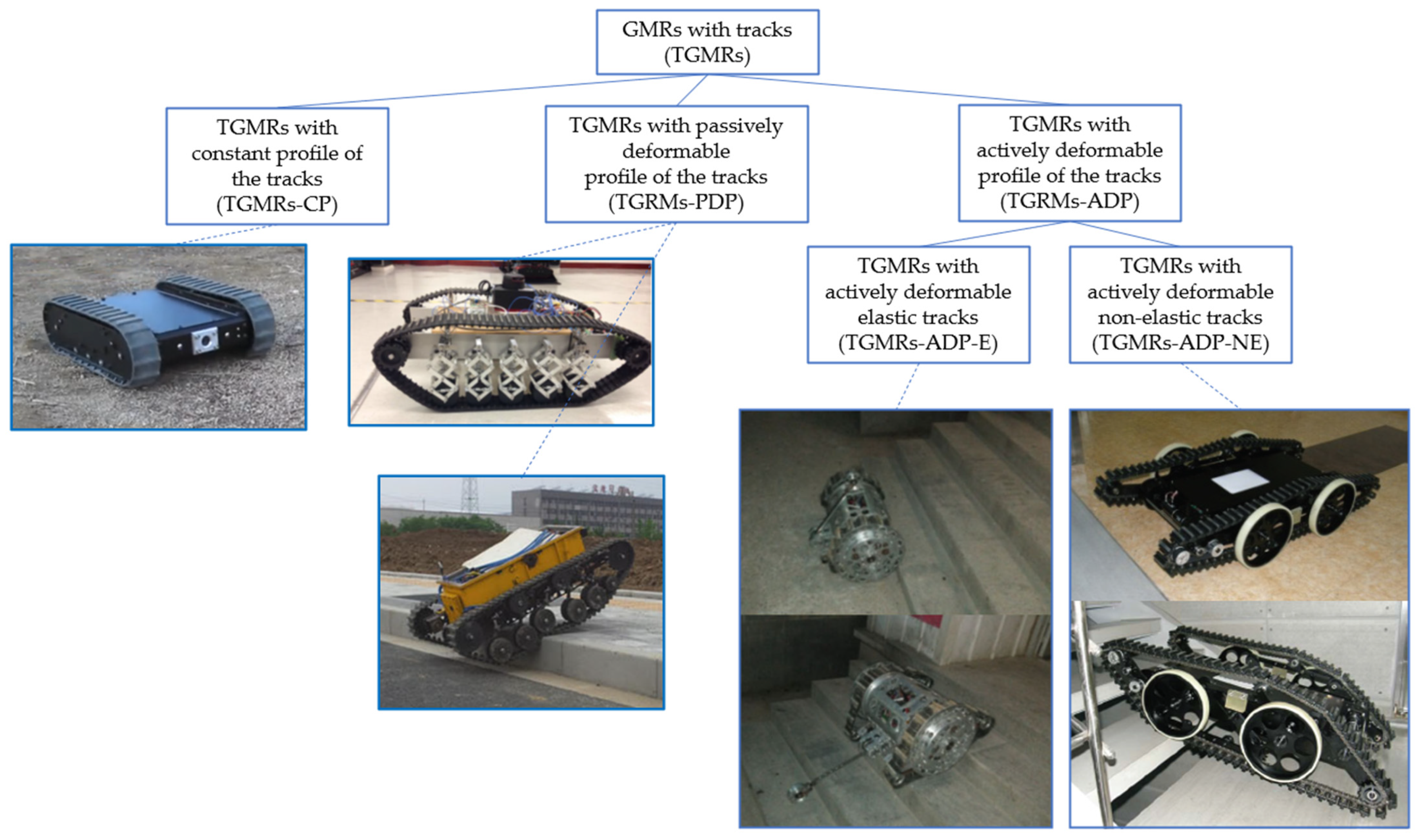
4. Classification of Track Profiles

Considering the track profile, TGMRs can be divided into three categories (Figure 5):
  • TGMRs with constant profile of the tracks (TGMRs-CP);
  • TGMRs with passively deformable profile of the tracks (TGMRs-PDP);
  • TGMRs with actively deformable profile of the tracks (TGMRs-ADP).
Let us note that even the track profile of robots belonging to the first category (TGMRs-CP) is not exactly constant, due to the unavoidable deformations of the tracks subject to gravity, contact forces with the terrain, and internal reactions (contacts with sprockets, idler sprockets, and carrier rollers). Nevertheless, the track supporting structure is designed to keep its shape constant, maintaining invariant the gross track profile. On the contrary, in the other two categories, the large variations of the track profiles, based on deformations in the geometry of the track-supporting structure, are functional features planned in the design phase. Most tracked robots belong to the TGMRs-CP category; for example, all the robots shown in Figure 2 are TGMRs-CP.
An example of TGMRs with passively deformable tracks (TGMRs-PDP) is discussed in [41]. In this robot (the upper TGMR-PDP in Figure 5), the carrier rollers are held by bio-inspired mechanisms, giving rise to compliance of the track profile, with benefits in terms of traction, obstacle climbing capabilities, and shock absorption; a similar solution is proposed in [42] (the lower TGMR-PDP in Figure 5), adopting slightly different suspension mechanisms.
While in TGMRs-PDP, the deformation of the track is determined by the distribution of the interaction forces between tracks and terrain, in TGMRs with actively deformable tracks (TGMRs-ADP), the shape change is commanded by actuators. There are two possible approaches to varying the track shape: with the first approach (TGMRs-ADP-E) the length of the track varies thanks to its elasticity; with the second approach (TGMRs-ADP-NE), the track profile varies but the track does not undergo macroscopic elongations.
An example of a TGMR-ADP-E is discussed in [43] (the TGMR-ADP-E in Figure 5). This robot is characterized by two wheels with a peripheral elastic track. In wheeled locomotion mode, the tracks adhere to the wheels. Each wheel has an internal four-link mechanism, actuated by self-locking worm gear motors, carrying two carrier rollers. When it is required to enable tracked locomotion, the two four-bar mechanisms move the carrier rollers outside the wheel profile, lengthening the elastic track. Moreover, both the track profile and the position of a rotating tail can be tuned depending on the obstacles to be climbed (Figure 5). This hybrid locomotion architecture has been demonstrated to be effective and reliable and has practical military and inspection applications.
An example of a TGMR-ADP-NE is presented in [44]; this robot is characterized by two differential-steering tracks, and each track is equipped with a rotating flipper that carries an idle wheel. The flippers are variable-length, elastically loaded, and keep the tracks properly tensioned independently of the flipper angle, maintaining constant the track length. The flipper angle is controlled in order to change the track shape: flat and longer to maximize the contact surface on soft terrains, triangular with variable front angle to face different obstacles.
The hybrid wheel-track robot proposed in [45] is another example of a TGMR-ADP-NE (Figure 5). It is characterized by two wheels and one track on each flank. Each track is supported by sprockets carried by a foldable articulated mechanism with a parallelogram outer shape. Acting on this articulated mechanism, the tracks can be folded, enabling wheeled locomotion, or unfolded for climbing obstacles, steps, and stairs.
The architecture proposed in [46] for stair climbing is a TGMR-ADP-NE characterized by a single track on each side, even if the robot body is divided into two parts connected by a revolute joint; therefore, the contact between tracks and sprockets must be maintained by an upper guidance system, thus losing symmetry for full operativity after a capsize.

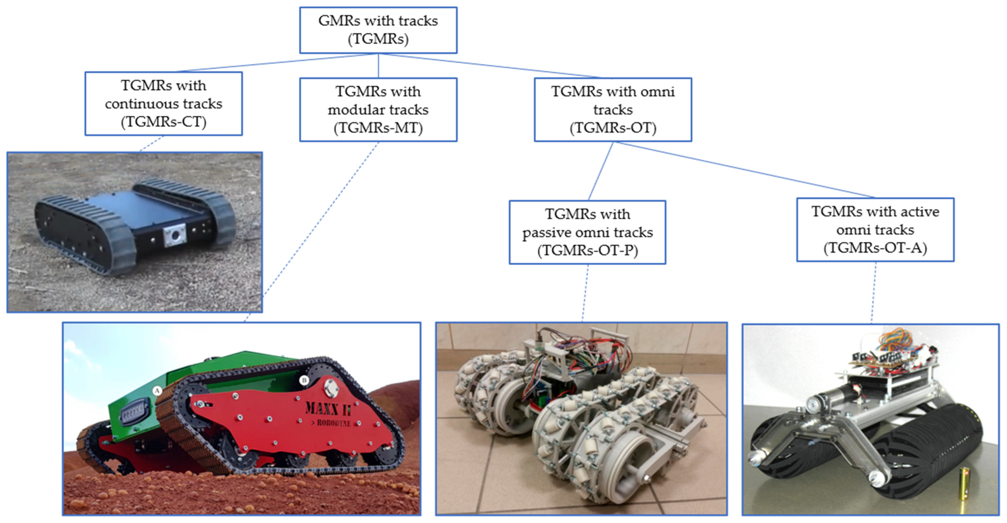
5. Classification of Track Types

On the basis of track realization, TGMRs can be classified as (Figure 6):
  • TGMRs with continuous tracks (TGMRs-CT);
  • TGMRs with modular tracks (TGMRs-MT);
  • TGMRs with omni tracks (TGMRs-OT).
Rubber continuous tracks are indeed the most widespread for robotic applications. For small-scale TGMRs, rubber continuous tracks without internal braiding are acceptable since the longitudinal structural stresses are small; moreover, their application is mandatory for TGMRs with actively deformable elastic tracks (TGMRs-ADP-E, Section 4). For heavier TGMRs, rubber tracks with textile or steel internal braiding are adopted, technologically similar to the tracks of small excavators and tracked vehicles. Continuous tracks have several advantages: extreme robustness to shocks and impacts, very good traction on soft and yielding terrains, and optimum capability of operating on sandy and muddy grounds.
Rubber continuous tracks are usually characterized by protrusions to increase traction on soft and irregular terrains; sometimes flat continuous tracks are adopted to join two functions: locomotion and compacting of bulk materials. For instance, in [47] a special-purpose service tracked robot is presented, capable of moving inside a truck container, and rolling over flax raw material to compress it, increasing its bulk density (Figure 7 left).
With regard to modular tracks, composed of modules connected by revolute joints, heavy vehicles usually adopt steel tracks, while for small robots the most common realization is based on high-strength plastic materials. Compared to rubber continuous tracks, the robustness to shocks and impacts is lower and there is a higher risk of locking on sandy and muddy terrains; on the other hand, the motion resistance due to the internal friction of the tracks is usually lower, and mounting and dismounting for maintenance is easier. Therefore, plastic modular tracks are usually adopted for small-size and lightweight TGMRs, as in [39], in which the structural resistance is not critical, to maximize the energetic efficiency. Nevertheless, there are examples of applications of modular tracks to larger TGMRs, such as the MAXXII, a mid-sized robot (length: 1 m, width: 0.7 m, mass: 40 kg, Figure 6), used for soil characterization through its passive suspension system, which is used as sensing device ([48], the TGMR-MT in Figure 6).
Sometimes, the modular realization allows the development of special-purpose tracks, tailored for particular applications. For instance, in [49] a small lightweight robot (186 × 125 × 51 mm, 200 g) with biologically-inspired spined track modules is proposed; to detach the spines from the surface, a mechanism is introduced to imitate the foot attaching and detaching movements of insects. The experimental tests have shown that the robot is capable of climbing on sandpaper, brick, coarse stucco, and pebble walls. Also, the robot proposed in [50] is small and lightweight (330 × 170 × 80 mm, 860 g), and has been designed using a biomimetic approach. It can climb concrete and brick walls using tracked-spines arrays located around the tracks. The robot uses a combination of the crank-link mechanism and gear transmission to control the tracked spines on both sides of the robot to grasp the asperities, climbing almost vertical walls.
Another very specific application of tracked robots with modular tracks is internal pipe climbing and inspection. For instance, in [51] a robot with three parallel track modules placed at 120° with axial symmetry around the robot’s longitudinal axis is discussed. During operation, an adequate contact force between the tracks and the internal pipe surface is granted by radial springs carrying the track modules. The operativity of this robot is evidently limited to a strict range of the pipe diameters. On the contrary, other robots for pipe inspection, equipped with magnetic modular tracks, can operate in larger pipes with different diameters, but obviously only in ferromagnetic material. For instance, the robot presented in [52] is equipped with two parallel tracks properly articulated to adapt to different pipe diameters and to improve maneuverability (Figure 7 right). In any case, pipe inspection robots are usually designed for this particular environment, and even if they can walk over different terrains, they cannot be considered general-purpose inspection platforms.
The third category based on track type is represented by TGMRs with omnidirectional tracks (TGMRs-OT), which can be further divided into robots with passive (TGMRs-OT-P) or active (TGMRs-OT-A) omnidirectional tracks. The functioning principle of omnidirectional tracks is similar to the one of omnidirectional wheels of Mecanum wheels [53]. A robot equipped with Mecanum wheels is holonomic, therefore the number of controlled degrees of freedom is equal to the number of degrees of mobility in the plane. This is particularly useful when the robot is required to operate in very limited spaces, moving in any direction. For instance, forklifts and transport robots with Mecanum wheels are adopted in storage facilities and production halls in which the organization of the spaces is of fundamental importance. On the other hand, Mecanum wheels also have considerable drawbacks. First of all, they have to operate preferably on flat, even, and clean surfaces. Moreover, their resistance to shocks and impacts is limited. Some researchers have proposed hybrid combinations of Mecanum wheels and tracks [54] (the TGMR-OT-P in Figure 6), realizing multidirectional tracks which have the same maneuverability advantages of the Mecanum wheels robot and better traction on uneven terrains, shock resistance, and capability of carrying loads, thanks to the higher number of rollers in contact with the terrain, and to the elasticity of the tracks. Nevertheless, due to the presence of rollers, the TGMRs-OT-P have still operative limitations in harsh environments.
An example of a TGMRs-OT-A is discussed in [55] (the TGMR-OT-A in Figure 6). Its architecture is characterized by two crawlers with a circular section; these crawlers have active rolling axes aligned with the longitudinal axis of the robot, to perform sideling motion whenever necessary while maintaining a large contact surface for motion on soft and yielding terrains. Even if there are no rollers directly in contact with the terrain as in TGMRs-OT-P, this locomotion system still suffers limitations due to the complex mechanical design of the crawlers.

6. Design Methodologies for Tracked Ground Mobile Robots

6.1. Modelling and Simulation of the Dynamic Behavior of TGMRs

The design of a tracked ground mobile robot has some peculiar aspects related to the functioning principle of the tracks, which are deformable bodies for TGMRs-CT, or composed of a closed chain of several rigid links connected by joints for TGMRs-MT and TGMRs-OT, and are in contact with the ground, which can have a wide range of properties, from firm surfaces to soft and yielding terrains.
In the scientific literature, there are many works about the dynamic modeling of the track–terrain interaction, oriented to the prediction of the motion of TGMRs given the terrain properties and the track velocities, which can be profitably exploited in the early design phases. While for wheeled robots the contact areas with the ground are relatively small with respect to the robot dimensions, for TGMRs the contact surface with the ground is remarkable, and macroscopic skidding is unavoidable during steering (skid steering). The mechanics of skid steering has attracted great interest over the last decades, with the pioneering works of Steeds [56], and the subsequent studies by Weiss [57], Crosheck [58], Kitano and Jyozaki [59], Ehlert et al. [60], which provided the analytical models used as the basis for the numerical simulations of the turning behavior of tracked vehicles.
In [61] a general theory for skid steering on firm ground is discussed, which shows a close agreement with experimental results. In [62] a simulation methodology for tracked vehicles on sandy terrain is discussed, capable of predicting sinkage, slip ratios, and turning radius.
When it is required to simulate the motion of a TGMR with a complex arrangement of the tracks and/or operating on irregular grounds and obstacles, it is unavoidable to adopt a numerical multibody approach. RecurDyn is often used as multibody package for the simulation of tracked vehicles and robots due to the availability of dedicated tools [63,64]. Another possible simulation approach, discussed in [65], exploits a high number of virtual wheels in the Gazebo environment to approximate track behavior.
Considering general simulation tools for mobile robotics, a survey and comparative study of Carmen, Player-Stage-Gazebo, Open Dynamics Engine, and Microsoft Robotics Developer Studio is presented in [66]. In particular, the combined use of Gazebo and of Robotic Operating System (ROS) for mobile robotics in research and education is very widespread and extensively discussed in the scientific literature [67,68,69].
The discussion of these modeling and simulation techniques, capable of assessing the motion capabilities of tracked robots in order to reduce the number of physical prototypes necessary to converge to the final design, is beyond the scope of this paper. However, the next Section summarizes the most widespread empirical models and methods used in the preliminary design of tracked systems to evaluate their motion resistance.

6.2. Motion Resistance of Tracks

The sizing of tracks (length, width) and of their motors on the basis of vehicle mass and desired performance is the most peculiar issue in the design of a tracked vehicle. This sizing must consider the features of the range of terrains on which the vehicle has to operate, adopting a proper terramechanics model.
The total motion resistance of a tracked vehicle, which has to be overcome by the actuators, is the sum of three terms:
  • The resistance Rt due to the interaction between tracks and terrain;
  • The resistance Rin due to the internal friction of the tracks;
  • The resistance Re due to the external forces acting on the vehicle.

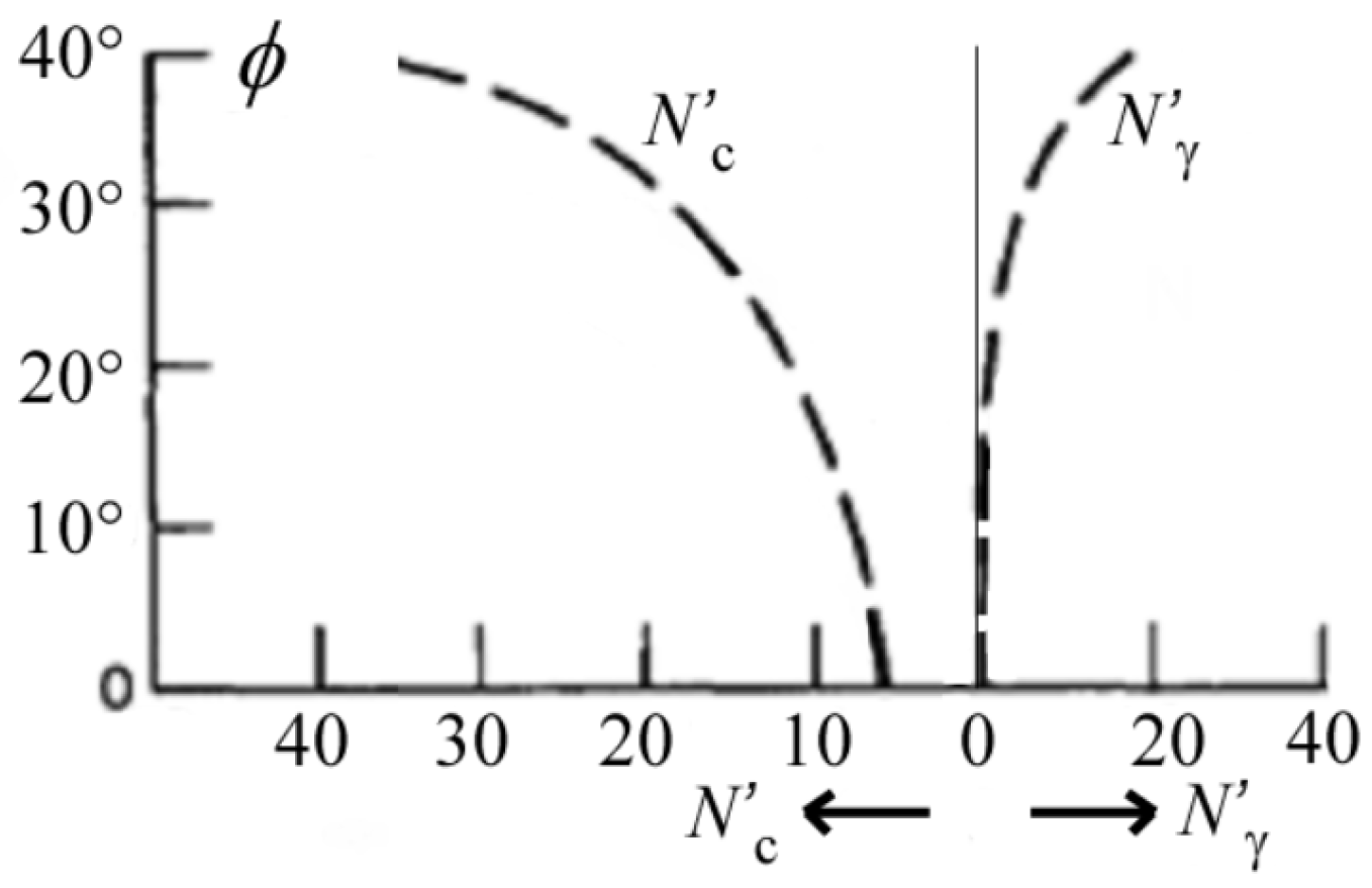
6.2.1. Motion Resistance Due to the Track–Terrain Interaction

The most widespread method to evaluate the interaction forces between tracks and ground is the Bekker model [70]. According to this approach, the track–terrain contact is assumed to be similar to a rigid footing; the deriving pressure–sinkage relationship allows to estimate the track sinkage and subsequently the motion resistance. For a track with uniform contact pressure, the sinkage z0 is given by:
z 0 = ( p k c / b + k ϕ ) 1 / n = ( W / b l k c / b + k ϕ ) 1 / n
where: p is the normal pressure; W is the normal load on the track (usually the portion of robot weight supported by the considered track); b and l are the width and length of the track; kc, kϕ, and n are characteristic parameters of the yielding terrain, available in the scientific literature [71]. Using Equation (1), it is possible to calculate the work necessary to compact the terrain while the robot goes forward, obtaining the compaction resistance Rc:
R c = b ( k c b + k ϕ ) z 0 n + 1 ( n + 1 )
Another component of the motion resistance is the so-called bulldozing resistance, due to the presence of yielding terrain in front of the track; the bulldozing resistance Rb can be calculated employing the following expression [72]:
R b = b ( 0.67 c z 0 ( N c tan ϕ ) cos 2 ϕ + 0.5 z 0 2 γ s ( 2 N γ tan ϕ + 1 ) cos 2 ϕ )
where: c is the terrain cohesion [Pa]; γs is the specific weight of the terrain [N/m3], Nc and Nγ are the Terzaghi’s modified bearing capacity factors, which are functions of the internal friction angle of the terrain ϕ according to the empirical relationships represented in Figure 8; the angle ϕ can be obtained by the following formula [72]:
tan ( ϕ ) = 2 3 tan ( ϕ )
Finally, the overall motion resistance due to the track–terrain interaction for a robot with n tracks can be obtained by summing the compaction and bulldozing resistances of each track:
R t = 1 n ( R c , i + R b , i )

6.2.2. Motion Resistance Due to the Internal Friction of the Tracks

The internal friction effects of the tracks obviously depend on the detailed design of tracks, drive sprockets, idler sprockets, upper and lower rollers (if present), and bearings. As a consequence, an accurate evaluation of this resistance term requires a complex mechanical modeling or an experimental evaluation, if a preliminary prototype is available. For example, it is possible to perform tests on flat and compact ground, in order to have negligible Rt. Another option, suitable only for a rough estimation, is the empirical formula proposed by Bekker [70]:
R i n = m ( 0.222 + 0.0108 v )
where Rin is the motion resistance [N] due to the internal friction of the tracks, m is the vehicle mass [kg] and v is the vehicle speed [m/s].

6.2.3. Motion Resistance Due to the External Forces

If the robot is not interacting with the environment during locomotion, for example by means of a robot arm, the motion resistance due to the external forces can be computed as the sum of the component of the weight acting in the motion direction and of the inertial forces:
R e = m g sin ( α ) + m e q a
where α is the terrain slope and a is the robot acceleration; the equivalent mass meq is the sum of the robot mass m and of the equivalent mass of the robot rotating bodies, obtained by kinetic energy equivalence. The equivalent mass meq is usually very close to m and can be approximated to it.

6.2.4. Overall Robot Motion Resistance

Using the previously discussed equations it is possible to select the main dimensions of the tracks (b, l), and to estimate the required torque and power of the track motors. Obviously, the detailed design of the tracks directly influences Rc and Rb, but also the internal friction resistance Rin and the vehicle mass m. Consequently, resistance Re is also indirectly influenced by b and l. Overall, these mutual relations among the vehicle characteristic parameters imply the need for a recursive design approach.
The two resistance components which are directly related to the track dimensions and to the terrain features are Rc and Rb. Figure 9 shows the sinkage z0 and the track–terrain motion resistance Rt, which is the sum of the compaction and bulldozing resistance, as functions of b and l, for one track of a two-tracked symmetrical robot with overall mass m = 40 kg. The considered terrain is dry sand characterized by the following parameters: kc = 0.99 kN/mn + 1, kϕ = 1528 kN/mn + 2, n = 1.1, c = 1.04 kPa, N’c = 16.5, N’γ = 5, ϕ = 28°, and γs = 17,800 N/m3.
It is possible to note that, as intuitive and evident from Equation (1), the sinkage decreases when the track width and length increase, and consequently also the terrain resistance decreases. The sensitivity to l is higher than the sensitivity to b. On the other hand, increasing b and l too much can be inconvenient for the overall vehicle dimensions; moreover, this increases the vehicle mass and consequently the resistance Re. Therefore, it is necessary to find a proper design trade-off, reaching a suitable compromise among these conflicting requirements.

7. Conclusions

In the fast-growing and quickly evolving field of service robotics, tracked ground mobile robots are attracting the attention of many researchers in the industrial and academic worlds. Tracked locomotion is particularly suited for soft and yielding terrains, but by adopting hybrid solutions, the range of profitable applicability of crawlers is greatly extended. The aim of this review is to outline the state-of-the-art of locomotion systems for TGMRs with a systematic approach, proposing three possible parallel taxonomies, respectively based on body architecture (Section 3), track profile (Section 4), and track type (Section 5), in order to help designers select the most suitable solution for the specific operative requirements.
The first taxonomy, based on the body configuration (Figure 2), first splits TGMRs into two categories, those with a non-articulated body (TGMRs-NA) and with an articulated body (TGMRs-A). TGMRs-NA are widely used for their mechanical and control simplicity and reliability, especially in the simplest, purely tracked realization (TGMRs-NA-T, [22]), while hybrid wheel-track solutions (TGMRs-NA-WT, [24]) have better maneuverability and range on compact grounds, but lower room for payload and greater weight. TGMRs-A can have a fully passive articulated body (TGMRs-A-P), a fully actuated articulated body (TGMRs-A-A), or a combination of passive and active degrees of freedom (TGMRs-A-AP). The most widespread architecture, which belongs to the TGMRs-A-A-LT-TOL subcategory (hybrid leg-track, with tracks on legs) is characterized by tracked rotating legs (flippers) to increase the obstacle climbing capability [30]; another trend is to use rotating legs with wheels placed at their ends to obtain hybrid leg-wheel-track architectures (TGMRs-A-A-LWT), with the benefits of wheeled locomotion, while maintaining simple mechanics and control [38,39].
Considering the second taxonomy (Figure 5), the track profile can be constant (TGMRs-CP), passively deformable (TGMRs-PDP), or actively deformable (TGMRs-ADP). TGMRs-CP are the most widespread for their simplicity, especially for small-scale realizations in which the structural resistance is less critical [22]. On the other hand, TGMRs-PDP are frequently larger, with passive suspension systems to filter impacts with obstacles and irregularities and to improve traction [42]. TGMRs-ADP solutions usually enable the switch from wheeled to tracked locomotion [43,45].
Regarding the third taxonomy (Figure 6), TGMRs can have continuous tracks (TGMRs-CT), modular tracks (TGMRs-MT), or omni tracks (TGMRs-OT). TGMRs-CT are undoubtedly the most widespread, especially for medium to large scale realizations, for the better structural features of the continuous tracks. Nevertheless, the modular realization of the tracks allows to accomplish specific functions, for example wall climbing with bio-inspired spines [49], or pipe inspection with magnetic tracks [52]. Omni tracks [54,55] are quite rarely adopted for their high mechanical complexity and low resistance to shocks.
In Section 6 the modeling and simulation methodologies for TGMRs, and some widely used empirical methods for the preliminary design of tracks are briefly summarized.
The present paper is focused exclusively on the locomotion systems of TGMRs, independently of the rest of the robot body, which can have very different functions and levels of complexity, from simple transport of environmental sensors and cameras [22,43] to manipulation with dexterous anthropomorphic arms and hands [36], and providing locomotion ability to disabled people [73].

Author Contributions

Conceptualization, L.B., S.E.N. and P.F.; methodology, L.B., S.E.N. and P.F.; software, L.B.; investigation, L.B., S.E.N. and P.F.; writing—original draft preparation, L.B.; writing—review and editing, P.F. and S.E.N. All authors have read and agreed to the published version of the manuscript.

Funding

This research received no external funding.

Institutional Review Board Statement

Not applicable.

Informed Consent Statement

Not applicable.

Data Availability Statement

Data is contained within the article. The numerical data presented in this study are available in figures and tables.

Conflicts of Interest

The authors declare no conflict of interest.

References

  1. International Federation of Robotics, World Robotics 2021, Industrial Robots and Service Robots. Available online: https://www.ifr.org (accessed on 11 April 2022).
  2. Mobile Robots Market by Operating Environment (Aerial, Ground, and Marine), Component (Control System, Sensors), Type (Professional and Personal & Domestic Robots), Application (Domestic, Military, Logistics, Field), and Geography—Global Forecast 2023. Available online: https://www.marketsandmarkets.com/Market-Reports/mobile-robots-market-43703276.html (accessed on 11 April 2022).
  3. Quaglia, G.; Visconte, C.; Scimmi, L.S.; Melchiorre, M.; Cavallone, P.; Pastorelli, S. Design of a UGV powered by solar energy for precision agriculture. Robotics 2020, 9, 13. [Google Scholar] [CrossRef] [Green Version]
  4. Wang, T.; Chen, B.; Zhang, Z.; Li, H.; Zhang, M. Applications of Machine Vision in Agricultural Robot Navigation: A Review. Comput. Electron. Agric. 2022, 198, 107085. [Google Scholar] [CrossRef]
  5. Mateo Sanguino, T.J. 50 years of rovers for planetary exploration: A retrospective review for future directions. Robot. Auton. Syst. 2017, 94, 172–185. [Google Scholar] [CrossRef]
  6. Thoesen, A.; Marvi, H. Planetary Surface Mobility and Exploration: A Review. Curr. Robot. Rep. 2021, 2, 239–249. [Google Scholar] [CrossRef]
  7. Nagatani, K.; Kiribayashi, S.; Okada, Y.; Otake, K.; Yoshida, K.; Tadokoro, S.; Takeshi, N.; Tomoaki, Y.; Koyanagi, E.; Mineo, F.; et al. Emergency Response to the Nuclear Accident at the Fukushima Daiichi Nuclear Power Plants using Mobile Rescue Robots. J. Field Robot. 2013, 30, 44–63. [Google Scholar] [CrossRef]
  8. Mattson, P.J.; Marshall, J.L. Homeland Security and Public Safety: Research. Applications and Standards; ASTM International: West Conshohocken, PA, USA, 2019. [Google Scholar]
  9. Gonzalez de Santos, P.; Cobano, J.A.; Garcia, E.; Estremera, J.; Armada, M.A. A six-legged robot-based system for humanitarian demining missions. Mechatronics 2007, 17, 417–430. [Google Scholar] [CrossRef]
  10. Saputra, R.P.; Rakicevic, N.; Kuder, I.; Bilsdorfer, J.; Gough, A.; Dakin, A.; de Cocker, E.; Rock, S.; Harpin, R.; Kormushev, P. Resqbot 2.0: An Improved Design of a Mobile Rescue Robot with an Inflatable Neck Securing Device for Safe Casualty Extraction. Appl. Sci. 2021, 11, 5414. [Google Scholar] [CrossRef]
  11. Chun, W.H.; Papanikolopoulos, N. Robot Surveillance and Security. In Springer Handbook of Robotics; Siciliano, B., Khatib, O., Eds.; Springer: Berlin/Heidelberg, Germany, 2016; pp. 1605–1626. [Google Scholar]
  12. Siegwart, R.; Nourbakhsh, I.R. Introduction to Autonomous Mobile Robots, 2nd ed.; The MIT Press: London, UK, 2011. [Google Scholar]
  13. Bruzzone, L.; Quaglia, G. Review Article: Locomotion Systems for Ground Mobile Robots in Unstructured Environments. Mech. Sci. 2012, 3, 49–62. [Google Scholar] [CrossRef] [Green Version]
  14. Rubio, F.; Valero, F.; Llopis-Albert, C. A Review of Mobile Robots: Concepts, Methods, Theoretical Framework, and Applications. Int. J. Adv. Robot. Syst. 2019, 16, 1–22. [Google Scholar] [CrossRef] [Green Version]
  15. Campion, G.; Bastin, G.; D’Andréa-Novel, B. Structural Properties and Classification of Kinematic and Dynamic Models of Wheeled Mobile Robots. IEEE Trans. Robot. Autom. 1996, 12, 47–62. [Google Scholar] [CrossRef]
  16. Siciliano, B.; Kathib, O. (Eds.) Springer Handbook of Robotics, 2nd ed.; Springer: Berlin/Heidelberg, Germany, 2016. [Google Scholar]
  17. Ceccarelli, M.; Kececi, E.F. (Eds.) Designs and Prototypes of Mobile Robots; ASME Press Robotics Engineering Book Series; Momentum Press Engineering: New York, NY, USA, 2015. [Google Scholar]
  18. Kececi, E.F.; Ceccarelli, M. (Eds.) Mobile Robots for Dynamic Environments; ASME Press Robotics Engineering Book Series; Momentum Press Engineering: New York, NY, USA, 2015. [Google Scholar]
  19. Patle, B.K.; Ganesh Babu, L.; Pandey, A.; Parhi, D.R.K.; Jagadeesh, A. A Review: On Path Planning Strategies for Navigation of Mobile Robot. Def. Technol. 2019, 15, 582–606. [Google Scholar] [CrossRef]
  20. Kunchev, V.; Jain, L.; Ivancevic, V.; Finn, A. Path Planning and Obstacle Avoidance for Autonomous Mobile Robots: A Review. In Knowledge-Based Intelligent Information and Engineering Systems; Gabrys, B., Howlett, R.J., Jain, L.C., Eds.; KES 2006; Lecture Notes in Computer Science; Springer: Berlin/Heidelberg, Germany, 2006; Volume 4252. [Google Scholar]
  21. Nakhaeinia, D.; Tang, S.H.; Noor, S.B.; Motlagh, O. A Review of Control Architectures for Autonomous Navigation of Mobile Robots. Int. J. Phys. Sci. 2011, 6, 169–174. [Google Scholar]
  22. Surveillance Security Robots Robotic Platform. Available online: https://www.inspectorbots.com/Home.html (accessed on 22 June 2022).
  23. Fukuoka, Y.; Oshino, K.; Ibrahim, A.N. Negotiating Uneven Terrain by a Simple Teleoperated Tracked Vehicle with Internally Movable Center of Gravity. Appl. Sci. 2022, 12, 525. [Google Scholar] [CrossRef]
  24. Ben-Tzvi, P.; Saab, W. A Hybrid Tracked-Wheeled Multi-Directional Mobile Robot. J. Mech. Robot. 2019, 11, 1–10. [Google Scholar] [CrossRef] [Green Version]
  25. Kim, J.; Kim, J.; Lee, D. Mobile Robot with Passively Articulated Driving Tracks for High Terrainability and Maneuverability on Unstructured Rough Terrain: Design, Analysis, and Performance Evaluation. J. Mech. Sci. Technol. 2018, 32, 5389–5400. [Google Scholar] [CrossRef]
  26. Hirose, S.; Shirasu, T.; Fukushima, E.F. Proposal for Cooperative Robot “Gunryu” composed of autonomous segments. Robot. Auton. Syst. 1996, 17, 107–118. [Google Scholar] [CrossRef]
  27. Haji, T.; Kinugasa, T.; Yoshida, K.; Amano, H.; Osuka, K. Experiment of Maneuverability of Flexible Mono-Tread Mobile Track and Differential-Type Tracked Vehicle. Ind. Robot. 2010, 37, 263–272. [Google Scholar] [CrossRef]
  28. Nodehi, S.E.; Bruzzone, L.; Fanghella, P. SnakeTrack, A Bio-inspired, Single Track Mobile Robot with Compliant Vertebral Column for Surveillance and Inspection. Mech. Mach. Sci. 2022, 120, 513–520. [Google Scholar] [CrossRef]
  29. Neumann, M.; Predki, T.; Heckes, L.; Labenda, P. Snake-like, Tracked, Mobile Robot with Active Flippers for Urban Search-and-Rescue Tasks. Ind. Robot. 2013, 40, 246–250. [Google Scholar] [CrossRef]
  30. Han, X.; Lin, M.; Wu, X.; Yang, J. Design of An Articulated-Tracked Mobile Robot with Two Swing Arms. In Proceedings of the 2019 IEEE 4th International Conference on Advanced Robotics and Mechatronics (ICARM), Toyonaka, Japan, 3–5 July 2019; pp. 684–689. [Google Scholar]
  31. Mitriakov, A.; Papadakis, P.; Kerdreux, J.; Garlatti, S. Reinforcement Learning Based, Staircase Negotiation Learning: Simulation and Transfer to Reality for Articulated Tracked Robots. IEEE Robot. Autom. Mag. 2021, 28, 10–20. [Google Scholar] [CrossRef]
  32. Yuan, Y.; Xu, Q.; Schwertfeger, S. Configuration-Space Flipper Planning on 3D Terrain. In Proceedings of the IEEE International Symposium on Safety, Security, and Rescue Robotics, Abu Dhabi, United Arab Emirates, 4–6 November 2020; pp. 318–325. [Google Scholar]
  33. Nagatani, K.; Kiribayashi, S.; Okada, Y.; Tadokoro, S.; Nishimura, T.; Yoshida, T. Redesign of Rescue Mobile Robot Quince—Toward Emergency Response to the Nuclear Accident at Fukushima Daiichi Nuclear Power Station on March 2011. In Proceedings of the 9th IEEE International Symposium on Safety, Security, and Rescue Robotics, Kyoto, Japan, 1–5 November 2011; pp. 13–18. [Google Scholar]
  34. Guo, W.; Qiu, J.; Xu, X.; Wu, J. TALBOT: A Track-Leg Transformable Robot. Sensors 2022, 22, 1470. [Google Scholar] [CrossRef]
  35. Ben-Tzvi, P.; Goldenberg, A.A.; Zu, J.W. Design, simulations and optimization of a tracked mobile robot manipulator with hybrid locomotion and manipulation capabilities. In Proceedings of the 2008 IEEE International Conference on Robotics and Automation (ICRA 2008), Pasadena, CA, USA, 19–23 May 2008; pp. 2307–2312. [Google Scholar] [CrossRef]
  36. Sun, Z.; Yang, H.; Ma, Y.; Wang, X.; Mo, Y.; Li, H.; Jiang, Z. BIT-DMR: A Humanoid Dual-Arm Mobile Robot for Complex Rescue Operations. IEEE Robot. Autom. Lett. 2022, 7, 802–809. [Google Scholar] [CrossRef]
  37. Sasaki, T.; Fujita, T. Gap Traversing Motion via a Hexapod Tracked Mobile Robot Based on Gap Width Detection. J. Robot. Mechatron. 2021, 33, 665–675. [Google Scholar] [CrossRef]
  38. Hong, S.; Wu, M.; Xiao, J.; Xu, X.; Lu, H. Kylin: A Transformable Track-Wheel Hybrid Robot. In Proceedings of the International Conference on Advanced Mechatronic Systems (ICAMechS 2018), Zhengzhou, China, 30 August–2 September 2018; pp. 7–12. [Google Scholar]
  39. Bruzzone, L.; Baggetta, M.; Nodehi, S.E.; Bilancia, P.; Fanghella, P. Functional Design of a Hybrid Leg-Wheel-Track Ground Mobile Robot. Machines 2021, 9, 10. [Google Scholar] [CrossRef]
  40. Gong, Z.; Xie, F.; Liu, X.J.; Shentu, S. Obstacle-Crossing Strategy and Formation Parameters Optimization of a Multi-Tracked-Mobile-Robot System with a Parallel Manipulator. Mech. Mach. Theory 2020, 152, 103919. [Google Scholar] [CrossRef]
  41. Li, Z.; Jing, X.; Sun, B.; Yu, J. Autonomous Navigation of a Tracked Mobile Robot with Novel Passive Bio-Inspired Suspension. IEEE/ASME Trans. Mechatron. 2020, 25, 2633–2644. [Google Scholar] [CrossRef]
  42. Li, Y.; Li, M.; Zhu, H.; Hu, E.; Tang, C.; Li, P.; You, S. Development and applications of rescue robots for explosion accidents in coal mines. J. Field Robot. 2020, 37, 466–489. [Google Scholar] [CrossRef]
  43. Gao, X.; Cui, D.; Guo, W.; Mu, Y.; Li, B. Dynamics and Stability Analysis on Stairs Climbing of Wheel-Track Mobile Robot. Int. J. Adv. Robot. Syst. 2017, 14, 1–13. [Google Scholar] [CrossRef]
  44. Malik, S.M.; Jun, L.; Goldenberg, A.A. Virtual Prototyping for Conceptual Design of a Tracked Mobile Robot. In Proceedings of the Canadian Conference on Electrical and Computer Engineering, Ottawa, ON, Canada, 7–10 May 2006; pp. 2349–2352. [Google Scholar]
  45. Kim, J.; Kim, Y.; Kwak, J.; Hong, D.; An, J. Wheel & Track hybrid robot platform for optimal navigation in an urban environment. In Proceedings of the SICE Annual Conference, Taipei, Taiwan, 18–21 August 2010; pp. 881–884. [Google Scholar]
  46. Zong, C.; Ji, Z.; Yu, H. Dynamic Stability Analysis of a Tracked Mobile Robot Based on Human–Robot Interaction. Assem. Autom. 2020, 40, 143–154. [Google Scholar]
  47. Galati, R.; Mantriota, G.; Reina, G. Design and Development of a Tracked Robot to Increase Bulk Density of Flax Fibers. J. Mech. Robot. 2021, 13, 1–10. [Google Scholar] [CrossRef]
  48. Galati, R.; Reina, G. Terrain Awareness Using a Tracked Skid-Steering Vehicle with Passive Independent Suspensions. Front. Robot. AI 2019, 6, 1–11. [Google Scholar] [CrossRef] [PubMed]
  49. Liu, Y.; Liu, S.; Wang, L.; Wu, X.; Li, Y.; Mei, T. A Novel Tracked Wall-Climbing Robot with Bio-inspired Spine Feet. In Proceedings of the International Conference on Intelligent Robotics and Applications ICIRA 2019, Shenyang, China, 8–11 August 2019; pp. 84–96. [Google Scholar] [CrossRef]
  50. Shi, J.; Xu, L.; Liu, J.; Cheng, G.; Liang, X.; Liu, L.; Chen, S.; Xu, H. Design, Simulation and Experimentation of a Biomimetic Wall-Climbing Robot with Tracked Spines. In Proceedings of the 2020 IEEE International Conference on Power, Intelligent Computing and Systems, ICPICS 2020, Shenyang, China, 28–30 July 2020; pp. 744–750. [Google Scholar] [CrossRef]
  51. Kumar, V.; Agarwal, S.; Vadapalli, R.; Govindan, N.; Krishna, K.M. Design and Analysis of Modular Pipe Climber-III with a Multi-Output Differential Mechanism. In Proceedings of the IEEE/ASME International Conference on Advanced Intelligent Mechatronics, Delft, The Netherlands, 12–16 July 2021. [Google Scholar]
  52. Bogdan, P.A.; Wheadon, J.; Klein, F.B.; Gianni, M. Magnetic Tracked Robot for Internal Pipe Inspection. In Proceedings of the 10th European Conference on Mobile Robots, Bonn, Germany, 31 August–3 September 2021. [Google Scholar] [CrossRef]
  53. Taheri, H.; Zhao, C.X. Omnidirectional Mobile Robots, Mechanisms and Navigation Approaches. Mech. Mach. Theory 2020, 153, 103958. [Google Scholar] [CrossRef]
  54. Fiedeń, M.; Bałchanowski, J. A Mobile Robot with Omnidirectional Tracks—Design and Experimental Research. Appl. Sci. 2021, 11, 11778. [Google Scholar] [CrossRef]
  55. Tadakuma, K.; Tadakuma, R.; Nagatani, K.; Yoshida, K.; Iagnemma, K. Crawler Mechanism with Circular Section to Realize a Sideling Motion. In Proceedings of the IEEE/RSJ International Conference on Intelligent Robots and Systems, Nice, France, 22–26 September 2008. [Google Scholar]
  56. Steeds, W. Tracked Vehicles. Automob. Eng. 1950 (3 parts) April 1950, pp. 143–148, May 1950, 187–190, June 1950, 219–222.
  57. Weiss, K.R. Skid-steering. Automob. Eng. 1971, 61, 22–25. [Google Scholar]
  58. Crosheck, J.E. Skid Steering of Crawlers. Trans. SAE 1975, 84, 1390–1404. [Google Scholar]
  59. Kitano, M.; Jyozaki, H. A Theoretical Analysis of Steerability of Tracked Vehicles. J. Terramechanics 1976, 13, 241–258. [Google Scholar] [CrossRef]
  60. Ehlert, W.; Hug, B.; Schmid, I.C. Field Measurements and Analytical Models as a Basis of Test Stand Simulation of the Turning Resistance of Tracked Vehicles. J. Terramechanics 1992, 29, 57–69. [Google Scholar] [CrossRef]
  61. Wong, J.Y.; Chiang, C.F. A General Theory for Skid Steering of Tracked Vehicles on Firm Ground. Proc. Inst. Mech. Eng. Part D J. Automob. Eng. 2001, 215, 343–355. [Google Scholar] [CrossRef]
  62. Thai, T.D.; Muro, T. Numerical Analysis to Predict Turning Characteristics of Rigid Suspension Tracked Vehicle. J. Terramechanics 1999, 36, 183–196. [Google Scholar] [CrossRef]
  63. Wu, Z.; Gao, Y.; Wang, D.; Yang, S. Unified Dynamic Simulation Analysis of Tracked Mobile Robot Based on RecurDyn. Mach. Des. Res. 2016, 32, 35–39. [Google Scholar]
  64. Tang, S.; Guo, Z.; Wang, G.; Wang, X. Comparative Performance Analysis of Different Travelling Mechanisms Based on RecurDyn. IOP Conf. Ser. Mater. Sci. Eng. 2020, 782, 042059. [Google Scholar] [CrossRef]
  65. Moskvin, I.; Lavrenov, R.; Magid, E.; Svinin, M. Modelling a Crawler Robot Using Wheels as Pseudo-Tracks: Model Complexity vs Performance. In Proceedings of the 7th IEEE International Conference on Industrial Engineering and Applications, Bangkok, Thailand, 16–21 April 2020. [Google Scholar] [CrossRef]
  66. Torres-Torriti, M.; Arredondo, T.; Castillo-Pizarro, P. Survey and Comparative Study of Free Simulation Software for Mobile Robots. Robotica 2016, 34, 791–822. [Google Scholar] [CrossRef]
  67. Iqbal, J.; Xu, R.; Sun, S.; Li, C. Simulation of an Autonomous Mobile Robot for LiDAR-Based in-Field Phenotyping and Navigation. Robotics 2020, 9, 46. [Google Scholar] [CrossRef]
  68. Costa, V.; Rossetti, R.; Sousa, A. Simulator for Teaching Robotics, ROS and Autonomous Driving in a Competitive Mindset. Int. J. Technol. Hum. Interact. 2017, 13, 19–32. [Google Scholar] [CrossRef] [Green Version]
  69. Rivera, Z.B.; De Simone, M.C.; Guida, D. Unmanned Ground Vehicle Modelling in Gazebo/ROS-Based Environments. Machines 2019, 7, 42. [Google Scholar] [CrossRef] [Green Version]
  70. Bekker, M.G. Theory of Land Locomotion; University of Michigan Press: Ann Arbor, MI, USA, 1962. [Google Scholar]
  71. Wong, J.Y. Theory of Ground Vehicles, 3rd ed.; John Wiley: New York, NY, USA, 2001. [Google Scholar]
  72. Bekker, M.G. Off-the-Road Locomotion: Research and Development in Terramechanics; University of Michigan Press: Ann Arbor, MI, USA, 1960. [Google Scholar]
  73. Quaglia, G.; Franco, W.; Nisi, M. Evolution of Wheelchair.q, a Stair-climbing Wheelchair. In Proceedings of the 14th IFToMM World Congress, Taipei, Taiwan, 25–30 October 2015; pp. 135–144. [Google Scholar] [CrossRef]
Figure 1. Mobility in unstructured environments vs. speed and energetic efficiency of the possible hybrid locomotion systems (Adapted with permission from [13], copyright 2012, L. Bruzzone and G. Quaglia).
Machines 10 00648 g001
Figure 2. Taxonomy of tracked ground mobile robots based on body architecture.
Machines 10 00648 g002
Figure 3. Dyjob robot, TGMR-NA with movable center of gravity: the center of gravity can be moved longitudinally to face the first step of a stair (left) or to maintain stability during gap traversing (center and right).
Machines 10 00648 g003
Figure 4. TALBOT, a quadruped robot with 3-DOF legs, in tracked mode (left) and in legged mode (right).
Machines 10 00648 g004
Figure 5. Taxonomy of tracked ground mobile robots based on track profile.
Machines 10 00648 g005
Figure 6. Taxonomy of tracked ground mobile robots based on track type.
Machines 10 00648 g006
Figure 7. TGMR-CT with flat tracks for flax raw material compacting (left); TGMR for pipe inspection with magnetic locomotion (right).
Machines 10 00648 g007
Figure 8. Terzaghi’s modified bearing capacity factors.
Machines 10 00648 g008
Figure 9. Track sinkage (z0, (left) [m]) and sum of compaction and bulldozing resistances (Rb + Rc, (right) [N]) as function of the track width b [m] and length l [m].
Machines 10 00648 g009
Publisher’s Note: MDPI stays neutral with regard to jurisdictional claims in published maps and institutional affiliations.

