Abstract
Asymmetric rolling (ASR) is a method to manufacture sheet metals with the aim of improving material performance. The objective of the present work is to investigate the effect of asymmetric rolling on an aluminum alloy used in the automotive industry. To this end, three parameters of the process were studied, namely the asymmetry factor (1, symmetric rolling (SR) and 1.36, asymmetric rolling (AR)), the thickness reduction per pass (10%, 15%, and 30%), and the rolling routes (asymmetric continuous (ARC) and asymmetric reverse (ARR)). After rolling, the material was tested by uniaxial tensile tests to measure its strength and formability. The results show similarity between all the rolling conditions, with a considerable increase in strength and a drastic decrease in formability. In addition, a prediction of forming limit diagram using an FLD code based on Marciniak–Kuczynski analysis was used to investigate the FLD evolution with rolling. The code was capable to capture the variation in formability during the rolling process, showing that it is a reliable numerical tool. A reasonable combination of high strength and acceptable formability was achieved by an adequate heat treatment applied after rolling.
1. Introduction
The actions demanded by climate transformation as a result of pollution caused by vehicles motivate many experts to seek solutions. One such solution is replacement of vehicles powered by gas with electric vehicles. However, an important aspect of the construction of all vehicles, independent of the type of motor, is vehicle weight. Aluminum alloys are good candidates, as they have an advantageous strength-to-weight ratio. The use of aluminum in car components can save 50% of the vehicle weight [1]. Nevertheless, the strength and formability of aluminum alloys are lower compared to other materials, such as high-strength steels, limiting their application in complex components of vehicles. The 6xxx series based on Al-Mg-Si alloys are the most used in automotive applications due to their positive welding qualities and good corrosion resistance, in addition to their reasonable strength and formability [2]. The reduced formability of aluminum alloys is associated with the development of cube texture component because of symmetric rolling and annealing [3,4,5]. In this view, to reduce or eliminate the formation of cube texture components, asymmetric rolling can be used to produce shear texture components, which are believed to possess improved material formability characteristics [6,7,8,9]. These components are obtained by a shear deformation produced through the thickness of the sheet, as opposed to two opposite shear deformations produced in symmetric rolling between both surfaces of the sheet and the mid plane. ASR is a type of rolling in which asymmetry is promoted during the process. This can be achieved by differences in (i) the diameter of the upper roll and bottom roll, (ii) the angular speed of each roll, or (iii) the friction coefficient between the contact surface of the sheet and the rolls. More details about the experimental aspects of the ASR technique can be found in the review paper by Vincze et al. [10].
Ren et al. [2] studied Al-Mg-Si alloys produced by ASR and identified a thermomechanical combination that leads to strength like that of T6 and T8 tempers while maintaining the tensile ductility of T3 tempers. This involves long heat treatments before and after rolling—16 h and 6–8 h, respectively. Sidor et al. [11] studied AA6016 processed by ASR. They found that with a ratio of 1.5 between the roll diameters, the shear texture after recrystallization improved the planar and normal anisotropy values, although no information regarding the formability of the material was specified. Amagadzie et al. [12] observed that for AA6061, ASR produces superior tensile properties compared to symmetric rolling, particularly when a high velocity ratio is used (i.e., 2.2). However, no important effect was observed with increased angular velocities of the rolls or rotation of the sheet between the subsequent rolling steps. Wronsky and colleagues [13] also studied AA6061 produced by ASR compared to symmetrical rolling (SR). They registered a higher strength and a much higher anisotropy for ASR samples compared to SR sampled. However, this increase in anisotropy was reduced during recrystallization. Cho and colleagues [14] obtained an improved equilibrium between strength and elongation in Al-Mg-Si alloys processed by symmetrical rolling in comparison with ASR. Lee and colleagues [15] successfully used an ASR process to increase the normal anisotropy value by about 1.3 times and decrease the planar anisotropy (ΔR) to 0.02 from 0.66 in AA1050. They applied 90% ASR deformation followed by annealing to produce shear texture components and . Then, the process continued with 20% ASR deformation, followed by annealing at 400 °C, during which the rotated cube was reduced, and the other component increased, leading to an improvement in anisotropy, as previously mentioned. One parameter related to material formability is the strain rate sensitivity. Bintu et al. [16] studied the effect of ASR on the strain rate sensitivity of AA5182 and observed that an increase in strain rate sensitivity occurs with for thickness reduction of more than 50%. Moreover, with a 90% thickness reduction, a decrease in annealing time led to a decrease in yield stress for SR, whereas for ASR, it led to an increase. AA5182 was also investigated by Tamimi et al. [6], who observed an increase in normal anisotropy, as well as an unfavorable increase in planar anisotropy. Gracio et al. [17] studied the formability of AA5182 using the M–K theory (Marciniak–Kuczynski) and input data from CPFEM (Crystal Plasticity FEM) and VPSC (viscoplastic self-consistent model). They observed that ARR can provide a good combination of formability with improved strength compared to the traditional processes. In a recent review, Pustovoytov et al. [18] concluded that asymmetric rolling is the most appropriate technique to produce materials with improved equilibrium of strength and ductility by severe plastic deformation for implementation at a large scale. Moreover, when dealing with grain refinement of aluminum alloys, special attention is required, a refinement can lead to a softening effect, as observed for Al-Zn alloys [19].
In conclusion, most of studies referring to the formability of material after ASR are related to the evolution of anisotropy and do not present information regarding formability.
In this work, we present new data on the mechanical behavior of one of the most important aluminum-magnesium-silicon alloys. Our attention is focused on the evolution of its strength and formability when processed by asymmetric rolling. Additionally, we investigate the adequate temperature of annealing treatment to apply to sheets to obtain increased formability after rolling. The aim of the present study was also to analyze the ability of the M-K model to predict material formability after ASR.
2. Materials and Experimental Methods
2.1. Asymmetric Rolling Mill
The asymmetric rolling mill used in this work is a homemade machine constructed at the Mechanical Engineering Department of the University of Aveiro, Portugal. Asymmetry is imposed by the difference between the rotational speed of the upper roll and that of the bottom roll. Each roll is connected to one gear motor with 2.2 kW and variable-frequency drive, which permits a variation of the speed between 0 and 15 RPM (rotation per minute). The interface that controls the roll’s speed was made using Melsec Medoc, Visual Basic, and ActiveX software. The two rolls have an equal diameter of 180 mm and a width of 300 mm. For accurate control of the sheet thickness, a level comparator (Mitutoyo, Japan) is mounted on each side of the mill. Figure 1 shows the rolling mill, and Figure 2 shows the user-friendly interface.
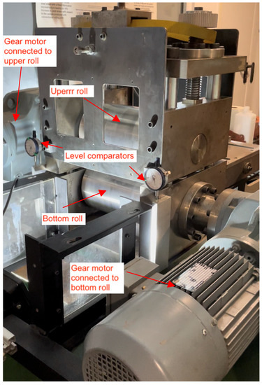
Figure 1.
Asymmetric rolling mill.
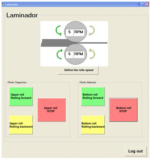
Figure 2.
User interface for rolling mill operation.
2.2. Rolling Conditions
Three rolling routes, as represented in Figure 3, were selected for the present study: symmetric rolling, continuous asymmetric rolling, and reverse asymmetric rolling. A total thickness reduction in the sheet of 50% was obtained by 3 reductions per pass, namely 10%, 15%, and 30%. The reductions per pass determined the number of passes required to reach the final thickness, which corresponded to 6, 4, and 2 passes, respectively. For each rolling route, three sheets with initial dimensions of 60 mm width and 70 mm length were rolled. For SR, the speed ratio of the rolls was 15:15, and for ASR, the ratio was 15:11, where 15 and 11 are the angular velocities measured in rpm.
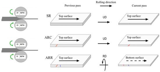
Figure 3.
Rolling routes employed in the present work. SR—symmetric rolling; ARC—continuous asymmetric rolling (no rotation of the sheet between two subsequent passes); ARR—reverse asymmetric rolling (rotation around the rolling direction between two subsequent passes).
A summary of the rolling routes and identification of the sample is presented in Table 1.

Table 1.
Identification of the samples according to the rolling conditions.
2.3. Mechanical Test
A uniaxial tensile test, plane strain test, and disk compression test were performed using a Shimadzu AG-X universal tensile test machine (Japan) with a load capacity of 100 kN. The geometry of the samples is presented in Figure 4. The samples were cut from the rolled sheet by a cutting press machine and machined by CNC. For the tensile test, the samples tested in one direction were cut from the same sheet. In the case of the plane strain test, only one sample per rolled sheet was obtained. The disk compression samples were cut from the remaining material of these sheets by electroerosion. A schematic representation of the relative position of the tensile test specimen on the rolled sheet is presented in Figure 4c. The strain was measured by an image correlation system and Aramis 5 M software (GOM, Germany). The testing setup is shown in Figure 5. For the determination of the experimental points included in forming limit diagram (FLC) the regulation given in ISO 12004-2:2008 was used.
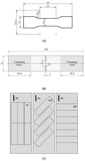
Figure 4.
Specimen dimensions: (a) tensile test specimen; (b) plane strain specimen; (c) position of tensile test specimens on the rolled sheet.
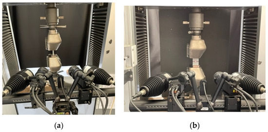
Figure 5.
Testing setup for tensile test (a) and plane strain test (b).
2.4. Material
The material used in this study is aluminum alloy 6022-T4 with an initial thickness of 2 mm. The chemical composition is given in Table 2. The mechanical properties of the as-received material are presented in Table 3.

Table 2.
Chemical composition of the as-received material (wt. %).

Table 3.
Mechanical properties of AA6022-T4 (RD, DD, and TD are rolling, diagonal, and transvers direction, respectively).
3. Brief Description of FLD Code
The theoretical forming limit diagrams presented in this work were calculated using the FLD code developed by Butuc et al. [20]. Plastic instability is simulated in the framework of heterogeneous materials using Marciniak–Kuczynski (M–K) analysis [21] coupled with the theory of plasticity. The M–K model is based on the growth of an initial geometric defect (f0) in the form of a narrow band of diminished thickness expressed by the ratio of the initial thickness in the groove to that of the homogeneous region. It is assumed that the material exhibits rigid plastic behavior. The initial yield locus shape is described by the Yld2000-2d plane stress yield criterion of Barlat et al. [22]. Plastic anisotropy is introduced by two linear transformations on the Cauchy stress tensor. The Yld2000-2d plane stress yield function, in terms of the deviatoric stress components, is expressed as:
where is the effective stress, a is an exponent connected to the crystal structure, and and are two isotropic functions defined by:
where and are the linear transformations of the effective stress tensor (s), which is defined as the deviatoric part of the Cauchy stress:
where C’ and C’’ are the material anisotropy coefficients.
The hardening behavior of the material is approximated by:
- (i)
- The Voce saturation strain-hardening law (Voce):where A, B, and C are the material constants. Each constant is calculated by fitting experimental stress/strain data;
- (ii)
- The Swift strain–hardening power law (Swift)where is the flow stress; the effective plastic strain; and K, , and n are material parameters.
4. Results and Discussion
First, the experimental results are presented in terms of the evolution of stress and strain with the rolling conditions, followed by the forming limit diagram prediction.
4.1. Mechanical Propeties after Rolling
4.1.1. Yield Stress and Ultimate Tensile Strength
The yield stress increases considerably as a result of rolling, as shown in Figure 6. A very small difference is observed between the rolling routes, with the lowest value corresponding to ARR. Regarding the evolution of yield stress of the in-plane anisotropy (at 0°, 45°, and 90° from the rolling direction), the highest values were achieved in the rolling direction (RD, 0°) although they were very close to the values obtained in the transverse direction (TD, 90°) and the diagonal direction (DD, 45°). Considering an average value of yield stress after rolling within all routes, there was an increase of 107 % compared to the as-received material. The ultimate tensile strength (UTS) follows the same trends but with a smaller increase, as shown in Figure 7. The increase in UTS is about 38%. This is due to the reduction in the strain-hardening rate of the rolled material in comparison with the hardening rate of the initial material.
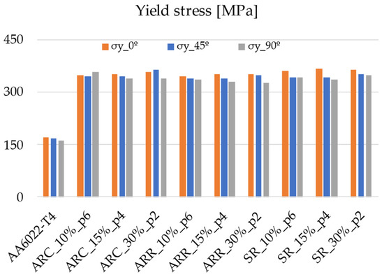
Figure 6.
Evolution of yield stress with rolling conditions.
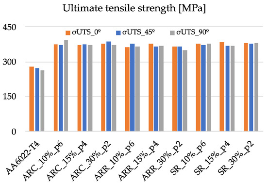
Figure 7.
Evolution of the ultimate tensile strength with rolling conditions.
4.1.2. Deformation
During the rolling process, the material accumulated a large amount of strain, which led to a considerable increase in stress, as previously observed. Thus, the material is expected to exhibit low performance in terms of deformation. Figure 8 shows a summary of uniform deformation for all rolling routes. Initially, the material shows the best formability/ductility for 45° from the rolling direction, whereas after rolling, this direction shows the lowest values of uniform deformation for most of the cases. The differences are very small within all three directions (less than 1% strain). Thus, when applying the same strategy as in the case of stress and calculating the decrease in strain, a reduction of 83% is observed in uniform deformation. The trends are similar for total deformation, with a decrease of about 73%. The results are shown in Figure 9.
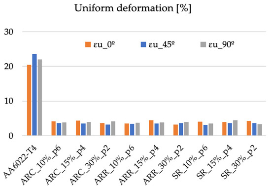
Figure 8.
Evolution of uniform deformation with rolling conditions.
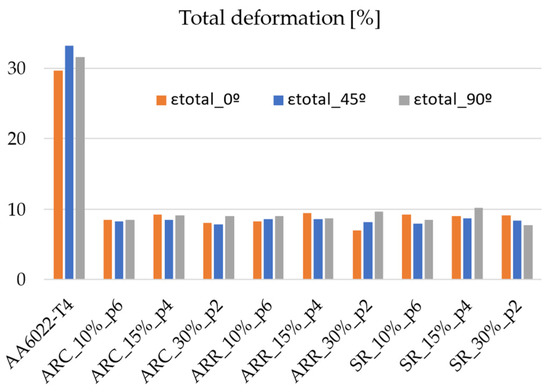
Figure 9.
Evolution of total deformation with rolling conditions.
4.1.3. Anisotropy
As presented in the Introduction, several authors suggest that ASR is capable of improving the plastic anisotropy of material, i.e., the normal anisotropy increases, whereas the planar anisotropy decreases. The Lankford coefficient was measured at the end of each type of rolling in three directions, namely 0°, 45°, and 90°. A summary of the results is presented in Figure 10. The initial material presents the highest R values for 0°, with a minimum at 45°. After rolling, the minimum R values remain at 45°, whereas the maximum values increase to 90°. This evolution of R values is observed for all rolling routes except one, i.e., ARC with 30 reductions per pass in two passes. In this case, the minimum occurs at 0°. Such behavior of the Lankford coefficient is related to the texture evolution during the rolling process. The texture evolution is beyond the scope of this work, in which anisotropy is analyzed from a macroscopic point of view. Using the Lankford coefficients, the average value of normal anisotropy ( value) and the planar anisotropy (ΔR) were calculated for all rolling routes. These results are presented in Figure 11 and Figure 12, respectively. The lowest value of corresponds to ARR routes, resulting in materials similar characteristics to those of the as-received material. For ARC and SR, a small increase in -value is obtained. The planar anisotropy shows a drop for all rolling routes, with the minimum corresponding to ARC. In addition, it seems that the planar anisotropy is also related to the number of passes and the thickness reduction per pass used in each rolling route, showing the same trend for ARC and ARR (i.e., ΔR decreases with the reduction in pass number) and an opposite trend for SR (i.e., ΔR increases with the reduction in pass number). For sheet-metal-forming applications, it seems that the best rolling route is ARC, as it is capable of producing a material with the lowest ΔR and highest value.
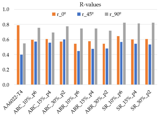
Figure 10.
Lankford coefficient evolution with the rolling conditions.
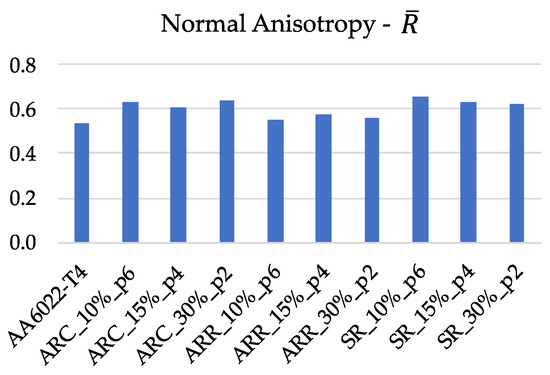
Figure 11.
-value evolution with the rolling conditions.
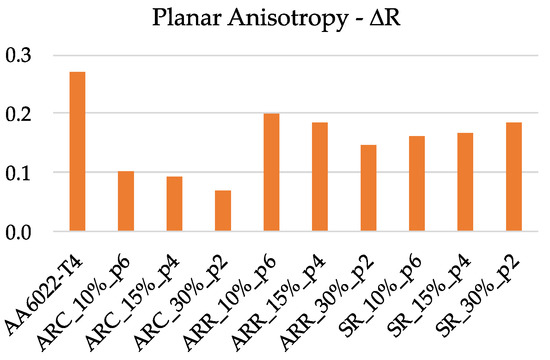
Figure 12.
Planar anisotropy (ΔR) evolution with the rolling conditions.
4.2. Recovery Heat Treatment after Rolling
Heat treatments (HT) in the range of 150–250 °C and 15–60 min were applied to the material after rolling to increase the formability. Temperatures below 200 °C are beneficial, leading to a small decrease in stress with increased strain. For temperatures above 200 °C, the stress decreases by about 100 MPa, and, unexpectedly, deformation also decreases. It seems that for this condition, the material reaches the overaged conditions. A study by Gracio et al. [23] regarding the artificial aging of AA6022 indicates that temperatures in the range of 240–260 °C for 10–20 min led to the peak age condition. In the present work, with temperatures of 250 °C/15 min, we obtained the overaged condition, possibly as a result of acceleration of the kinetics of the precipitates due to cold deformation, as detected by Yassar et al. [24] in the same aluminum alloy. Of the tested temperatures, the combination of 150 °C/45 min, 175 °C/30 min, and 175 °C/45 min seems to be the best choice. The variation in strain under these annealing conditions is up to 1%, and the variation in stress is up to 15 MPa. Annealing increases both types of anisotropy, leading to an improvement compared to the initial material, as shown in Figure 13e,f. The effect of recovery at 175 °C for 45 min for samples cut in the RD is summarized in Figure 13.
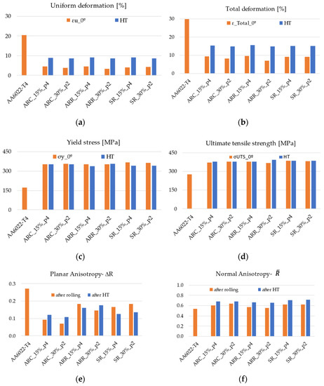
Figure 13.
Effect of annealing in mechanical properties of rolled material.
4.3. FLD Prediction
Table 4 lists the anisotropy parameters for the Yld2000-2d yield function. They are calculated, for each selected case, by a numerical identification from the experimental data containing three yield stresses (σ0, σ45, and σ90) and three R values (r0, r45, and r90) from uniaxial tension, the biaxial R-value (rb), and the balanced biaxial yield stress (σb), approximated by σ0, following the observation of Woodthorpe and Pearce [25] for materials exhibiting R values less than 1, since there is no experimental value for it. The exponent “a” of the yield function has a value of 8, which is recommended for materials with a face-centered cubic crystal structure. This parameter controls the sharpness of the yield locus in equibiaxial stretching, which is important in FLD predictions. Table 5 lists the Swift hardening law parameters determined by fitting of experimental true stress–plastic strain curves.

Table 4.
Anisotropy coefficients of the Yld2000-2d yield function.

Table 5.
Determined Swift parameters.
Figure 14 shows the evolution of the anisotropy factor (a) and of the yield stress (b) as a function of the tensile loading axis between 0° and 90°. The anisotropic yield criterion (Yld2000-2d) characterizes very well the initial plastic anisotropy of the studied AA6022-T4-T4 sheet, as expressed by the yield stresses and R values. The predicted normalized yield stresses and anisotropy factors accurately reproduce the experimental values and their entire distribution. An excellent match between the experimental points represented by markers and the predicted curves is observed. A decrease in R values for RD and an increase in R values for DD and TD of approximately the same amount (0.2) were observed.
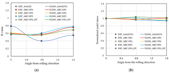
Figure 14.
Evolution of R values (a) and normalized yield stress (b) with rolling.
The plane stress yield surfaces of the AA6022-T4-T4 sheet are presented in Figure 15. The balanced biaxial yield stress used as input in the Yld2000-2d coefficient, assures a great accuracy in reproducibility of the yield surface in the critical region of biaxial stretching. The effect of ARC on the yield surface is observed in DD and TD through the normalized values of σ45 and σ90.
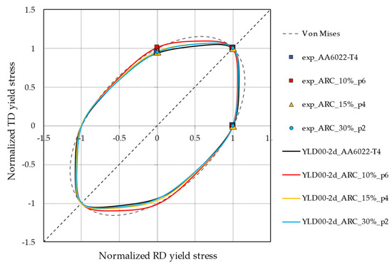
Figure 15.
Evolution of the yield surface of AA6022-T4-T4 with rolling.
Figure 16 shows the experimental forming limits for the AA6022-T4-T4 sheet under proportional loading, as well as those simulated with the selected constitutive equations, namely the Yld2000-2d yield function with the Voce hardening law and the Swift hardening law. To achieve the agreement with the experimental data, the initial value of the M–K geometric defect of 0.9945 and the material strain hardening described by the Swift hardening law were adopted throughout this investigation. The forming limits predicted using the Voce hardening law are underestimated for an f0 of 0.998, an appropriate value for FCC materials, as suggested by Barlat [26]. An f0 of 0.9998, chosen to increase the predicted values, results in an under evaluation of the left-hand side of the FLD, whereas the right-hand side is substantially overpredicted. The choice of Swift hardening law corroborates a study by Haque and Yoon [25], who found that the Swift law fits better than Voce law for the hardening of the AA6022-T4-T4 sheet. The strain paths are characterized by the stress ratio (α), expressed as σ2/σ1, and by the strain ratio (ρ), expressed as dε2/dε1, respectively. The acronyms UT, PS, and BS are used for uniaxial tension, plane strain, and biaxial stretching, respectively.
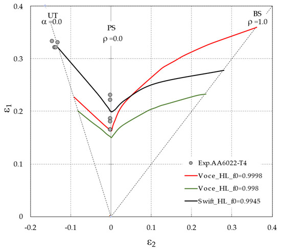
Figure 16.
Experimental and theoretical FLDs of AA6022-T4 sheet using the YLD2000-2d yield function with the Voce law and the Swift law.
Due to the similar results in terms of deformation, FLD prediction was studied only for the ARC route. The effect of ARC on the FLD of the AA6022-T4 sheet is analyzed by comparing the FLD of the original AA6022-T4 sheet with that obtained after applying ARC conditions, namely ARC_15%_p4 and ARC_30%_p2. These results are shown in Figure 17.
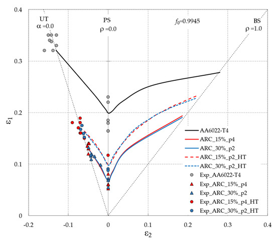
Figure 17.
The effect of ARC conditions on the FLDs of AA6022-T4 sheets.
A strong decrease in the forming limits is observed after ARC, in particular, a decrease of 20% in the UT forming limit, 13% in the PS forming limit, and 8.5% in the BS forming limit. The application of annealing allows for an increase in the forming limits of the entire FLD of approximately 4% in comparison to those obtained in the ARC cases. The FLD model captures the significant decrease in formability resulting from ARC conditions, as well as the increase in formability resulting from the application of annealing to the sheet, accompanying the experimental tendencies and achieving good proximity of the predicted FLD curves to the experimental points.
The effect of ARC conditions on the predicted FLDs is explained by the impact of such an effect on the mechanical properties of the material, which are correctly reproduced by the selected constitutive equations. The substantial decrease in the entire FLD after ARC is due to the considerable reduction in the material strain hardening, which is strictly connected with the forming limits. The decrease in the work hardening coefficient allows for a considerable decrease in the forming limit strains [27]. In our case, the n value of 0.256 of the initial AA6022-T4 sheet decreases to 0.17 in ARC cases. This considerable diminution of the work hardening coefficient allows for a drastic reduction in the forming limits. In addition to the decrease in n values, the increase in prestrain amount accumulated during rolling (associated with the ε0 parameter of Swift law) also leads to a decrease in the FLD curve. After recovery-type annealing, the dislocation density decreases, leading to an increase in the n values and a decrease of ε0 compared with the values obtained as a result of ARC conditions. Specifically, the n value of 0.17 after rolling increases to 0.185, which allows for an augmentation of the forming limits compared to those obtained as a result of ARC conditions.
In agreement with the results reported by Butuc et al. [28] the anisotropy factors have no effect on the left side of the FLD, whereas the forming limits of the right side are significantly increased with an increase in the r0 value. Furthermore, a slight decrease in the forming limits with an increase in the r90 value for low minor strains, as well as an inversion of this effect for larger minor strains, is observed. r45 has no effect on the predicted forming limits. As shown in Figure 14a, following ARC a decrease in the values of r0 and an increase in the values of r90 are observed in all study cases. The decrease in r0 allows for a decrease in the forming limits on the right-hand side of the FLD, whereas an increase in r90 can be associated with a slight increase in the FLD. Because the effect of the r0 value is more pronounced than the r90 effect, a part of the decrease in the FLD after ARC can be attributed to the decrease in the r0 values. The effect of the annealing applied to the material on the anisotropy of the AA6022-T4 sheet is not significant, therefore the increase in the FLD_HT by compared with the FLD_ARC is due to the increase in the material strain hardening after annealing.
5. Conclusions
The effect of the asymmetric rolling process on the mechanical properties of AA6022 was investigated; the main conclusions are drawn below:
- Symmetric and asymmetric rolling conditions lead to similar results in terms of stress and strain, namely a considerable increase in yield stress (>100%), a moderate increase in ultimate tensile strength (~40%), and a considerable decrease in uniform and total strain (~70–80%);
- The normal anisotropy decreases in the RD direction and increases in the DD and TD directions compared to the Lankford coefficients of material before rolling by approximately 0.2. The planar anisotropy decreases for all routes and shows a dependence on the rolling route, with a minimum for ARC conditions. The maximum reduction, which corresponds to approximately 70%, is reached for ARC_30%_p2. The normal anisotropy shows a very slight increase and is almost insensitive to the rolling routes. However, for the same route, the most considerable increase occurs with ARC_30%_p2, corresponding to 20%. The advantageous evolution of anisotropy can be obtained by the ARC process;
- To increase the formability, annealing in the range of temperatures of 150–175 °C for 30–45 min is recommended;
- The selected constitutive equations, namely the Yld2000-2d yield function and the Swift strain–hardening power law, as well as the FLD code, accurately capture the evolution of the mechanical properties and the formability of an AA6022-T4 sheet through the asymmetric rolling process.
Author Contributions
Conceptualization, G.V. and M.C.B.; investigation, writing—original draft preparation, M.C.B. and G.V.; formal analysis, G.V., M.C.B. and A.B.P.; experimental work, D.A.F.L. and J.M.V.Y.; data processing D.A.F.L., J.M.V.Y. and G.V.; writing—review and editing, G.V., M.C.B. and A.B.P.; project administration, G.V. and M.C.B.; funding acquisition, G.V., M.C.B. and A.B.P. All authors have read and agreed to the published version of the manuscript.
Funding
This work was supported by the projects POCI-01-0145-FEDER-032362 (PTDC/EME-ESP/32362/2017), financed by the Operational Program for Competitiveness and Internationalization, in its FEDER/FNR component; and the Portuguese Foundation of Science and Technology (FCT), in its State Budget component (OE), UIDB/00481/2020 and UIDP/00481/2020-FCT-Portuguese Foundation of Science and Technology; and CENTRO-01-0145-FEDER-022083-Centro Portugal Regional Operational Program (Centro2020), under the PORTUGAL 2020 Partnership Agreement, through the European Regional Development Fund.
Acknowledgments
The authors acknowledge the support of General Motors for supplying the material investigated in this work.
Conflicts of Interest
The authors declare no conflict of interest.
References
- Hirsch, J. Aluminium in Innovative Light-Weight Car Design. Mater. Trans. 2011, 52, 818–824. [Google Scholar] [CrossRef] [Green Version]
- Ren, J.; Chen, Z.; Peng, J.; Ma, W.; Ringer, S.P. An initial report on achieving high comprehensive performance in an Al-Mg-Si alloy via novel thermomechanical processing. J. Alloys Compd. 2018, 764, 676–683. [Google Scholar] [CrossRef]
- Hirsch, J.; Al-Samman, T. Superior light metals by texture engineering: Optimized aluminum and magnesium alloys for automotive applications. Acta Mater. 2013, 61, 818. [Google Scholar] [CrossRef]
- Ma, C.Q.; Hou, L.G.; Zhang, J.S.; Zhuang, L.Z. Experimental and Numerical Investigations of the Plastic Deformation during Multi-Pass Asymmetric and Symmetric Rolling of High-Strength Aluminum Alloys. Mater. Sci. Forum. 2014, 794–796, 1157–1162. [Google Scholar] [CrossRef]
- Kang, S.B.; Min, B.K.; Kim, H.W.; Wilkinson, D.S.; Kang, J. Effect of asymmetric rolling on the texture and mechanical properties of AA6111-aluminum sheet. Metall. Mater. Trans. 2005, 36, 3141–3149. [Google Scholar] [CrossRef]
- Tamimi, S.; Correia, J.P.; Lopes, A.B.; Ahzi, S.; Barlat, F.; Gracio, J.J. Asymmetric rolling of thin AA-5182 sheets: Modelling and experiments. Mater. Sci. Eng. A 2014, 603, 150–159. [Google Scholar] [CrossRef]
- Son, S.; Kim, H.-K.; Cho, J.-H.; Kim, H.-W.; Lee, J.-C. Differential speed rolling of twin-roll-cast 6xxx al alloy strips and its influence on the sheet formability. Met. Mater. Int. 2015, 22, 108–117. [Google Scholar] [CrossRef]
- Jin, H.; Lloyd, D. The tensile response of a fine-grained AA5754 alloy produced by asymmetric rolling and annealing. Metall. Mater. Trans. 2004, 35, 997–1006. [Google Scholar] [CrossRef]
- Choi, C.-H.; Kim, K.-H.; Lee, D.N. The effect of shear texture development on the formability in rolled aluminum alloy sheets. Mater. Sci. Forum. 1998, 273–275, 391–396. [Google Scholar] [CrossRef]
- Vincze, G.; Simões, F.J.P.; Butuc, M.C. Asymmetrical Rolling of Aluminum Alloys and Steels: A Review. Metals (Basel) 2020, 10, 1126. [Google Scholar] [CrossRef]
- Sidor, J.; Miroux, A.; Petrov, R.; Kestens, L. Controlling the plastic anisotropy in asymmetrically rolled aluminium sheets. Philos. Mag. 2008, 88, 3779–3792. [Google Scholar] [CrossRef]
- Amegadzie, M.Y.; Bishop, D.P. Effect of asymmetric rolling on the microstructure and mechanical properties of wrought 6061 aluminum. Mater. Today Commun. 2020, 25, 101283. [Google Scholar] [CrossRef]
- M Wronski, M.; Wierzbanowski, K.; Wronski, S.; Bacroix, B.; Wróbel, M.; Uniwersał, A. Study of texture, microstructure and mechanical properties of asymmetrically rolled aluminium. IOP Conf. Series Mater. Sci. Eng. 2015, 82, 012074. [Google Scholar] [CrossRef]
- Cho, J.-H.; Kim, H.; Lim, C.-Y.; Kang, S.-B. Microstructure and mechanical properties of Al-Si-Mg alloys fabricated by twin roll casting and subsequent symmetric and asymmetric rolling. Met. Mater. Int. 2014, 20, 647–652. [Google Scholar] [CrossRef]
- Lee, J.-H.; Kim, G.-H.; Nam, S.K.; Kim, I.; Lee, D.N. Calculation of plastic strain ratio of AA1050 Al alloy sheet processed by heavy asymmetric rolling–annealing followed by light rolling–annealing. Comput. Mater. Sci. 2015, 100, 45–51. [Google Scholar] [CrossRef]
- Bintu, A.; Vincze, G.; Picu, R.; Lopes, A. Effect of symmetric and asymmetric rolling on the mechanical properties of AA5182. Mater. Des. 2016, 100, 151–156. [Google Scholar] [CrossRef]
- Grácio, J.J.D.A.; Vincze, G.; Yoon, J.W.; Cardoso, R.P.R.; Rauch, E.F.; Barlat, F.G. Modeling the Effect of Asymmetric Rolling on Mechanical Properties of Al-Mg Alloys. Steel Res. Int. 2015, 86, 922–931. [Google Scholar] [CrossRef]
- Pustovoytov, D.; Pesin, A.; Tandon, P. Asymmetric (Hot, Warm, Cold, Cryo) Rolling of Light Alloys: A Review. Metals 2021, 11, 956. [Google Scholar] [CrossRef]
- Borodachenkova, M.; Barlat, F.; Wen, W.; Bastos, A.; Grácio, J. A microstructure-based model for describing the material properties of Al–Zn alloys during high pressure torsion. Int. J. Plast. 2015, 68, 150–163. [Google Scholar] [CrossRef] [Green Version]
- Butuc, M.C.; Teodosiu, C.; Barlat, F.; Grácio, J.J. Analysis of sheet metal formability through isotropic and kinematic hardening models. Eur. J. Mech. A Solids 2011, 30, 532–546. [Google Scholar] [CrossRef] [Green Version]
- Marciniak, Z. Analysis of necking preceding fracture of sheet metal under tension. Met. Ital. 1968, 60, 701–709. [Google Scholar]
- Barlat, F.; Brem, J.C.; Yoon, J.W.; Chung, K.; Dick, R.E.; Lege, D.J.; Pourboghrat, F.; Choi, S.-H.; Chu, E. Plane stress yield function for aluminum alloy sheets. Part 1: Theory. Int. J. Plasticity 2003, 19, 1297–1319. [Google Scholar] [CrossRef]
- Gracio, J.J.; Barlat, F.; Rauch, E.F.; Jones, P.T.; Neto, V.F.; Lopes, A.B. Artificial aging and shear deformation behavior of 6022 Al alloy. Int. J. Plast. 2004, 20, 427–445. [Google Scholar] [CrossRef]
- Yassar, R.S.; Field, D.P.; Weiland, H. The effect of cold deformation on the kinetics of the β″ precipitates in an Al-Mg-Si alloy. Metall. Mater. Trans. 2005, 36, 2059–2065. [Google Scholar] [CrossRef]
- Woodthorpe, J.; Pearce, R. The anomalous behaviour of aluminium sheet under balanced biaxial tension. Int. J. Mech. Sci. 1970, 12, 341–347. [Google Scholar] [CrossRef]
- Barlat, F. Forming Limit Diagrams-Predictions based on some microstructural aspects of materials, Forming Limit Diagrams: Concept, Methods and Applications. Miner. Met. Mater. Soc. 1989, 275–301. [Google Scholar]
- Haque, Z.; Yoon, J.W. Stress based prediction of formability and failure in incremental sheet forming. Int. J. Mater. Form. 2016, 9, 413–421. [Google Scholar] [CrossRef]
- Butuc, M.C.; Barlat, F.; Vincze, G. The formability of twinning—Induced plasticity steels predicted on the base of Marciniak-Kuczynski theory. J. Mater. Process. Technol. 2019, 287, 116496. [Google Scholar] [CrossRef]
Publisher’s Note: MDPI stays neutral with regard to jurisdictional claims in published maps and institutional affiliations. |
© 2022 by the authors. Licensee MDPI, Basel, Switzerland. This article is an open access article distributed under the terms and conditions of the Creative Commons Attribution (CC BY) license (https://creativecommons.org/licenses/by/4.0/).