Article

Virtual and Real Bidirectional Driving System for the Synchronization of Manipulations in Robotic Joint Surgeries

1
College of Artificial Intelligence, Nankai University, Tianjin 300350, China
2
Institute of Intelligence Technology and Robotic Systems, Shenzhen Research Institute of Nankai University, Shenzhen 518083, China
*
Author to whom correspondence should be addressed.
Machines 2022, 10(7), 530; https://doi.org/10.3390/machines10070530
Submission received: 21 May 2022 / Revised: 22 June 2022 / Accepted: 27 June 2022 / Published: 29 June 2022

Abstract

:
Surgical robots are increasingly important in orthopedic surgeries to assist or replace surgeons in completing operations. During joint surgeries, the patient’s joint needs to be adjusted several times by the surgeon. Therefore, the virtual model, built on the preoperative medical images, cannot match the actual variation of the patient’s joint during the surgery. Conventional virtual reality techniques cannot fully satisfy the requirements of the joint surgeries. This paper proposes a real and virtual bidirectional driving method to synchronize the manipulations in both the real operation site and the virtual scene. The dynamic digital twin of the patient’s joint is obtained by decoupling the joint and dynamically updating its pose via the intraoperative measurements. During surgery, the surgeon can intuitively monitor the real-time position of the patient and the surgical tool through the system and can also manipulate the surgical robot in the virtual scene. In addition, the system can provide visual guidance to the surgeon when the patient’s joint is adjusted. A prototype system is developed for orthopedic surgeries. Proof-of-concept joint surgery demo is carried out to verify the effectiveness of the proposed method. Experimental results show that the proposed system can synchronize the manipulations in both the real operation site and the virtual scene, thus realizing the bidirectional driving.

1. Introduction

1.1. Background and Significance

Surgical robots are increasingly utilized to assist or replace surgeons in completing surgery operations [1,2,3]. Their high-precision operation capability and reliability are very attractive in surgeries [4,5]. In clinics, each surgeon needs to be trained for years so as to acquire qualifications. On the contrary, robots do not have to be trained for such a long time, and the program of one robot can be easily transferred to another robot. The most representative surgical robot is the Da Vinci surgical robot, which can be used in a variety of surgeries [6,7,8]. For spinal surgery robots, the Mazor X from Medtronic has improved flexibility and working range, and can position individual vertebral segments [9,10]. The ROSA robot from MedTech is used for spinal surgery, and it can adjust the position of the robot according to the patient’s breathing [11]. For the knee joint surgery, the representative one is the ROBODOC surgical robot developed in the 1990s [12]. It can complete the surgical operation according to the planned robot trajectory. The CASPER surgical robot can assist surgeons in the positioning and installation of the prostheses during joint surgery [13]. The MAKO [14,15] surgical robotic system uses haptics to guide the surgery, and defines the surgical field based on the preoperative medical images, ensuring that the cutting does not cross the defined boundaries.
Medical images are important for surgical robots as the surgery planning and intraoperative registration all depend on the medical images of the patient. Digital twin is the virtual analogy of the physical object, which can be used to simulate [16], analyze [17], and monitor the physical object [18]. It can be used in surgeries so as to facilitate the surgeons in preoperative planning or intraoperative surgery [19]. For instance, digital twin-based systems were developed to accurately predict the diameter of the tumor [20], the adverse side effects caused by the deep brain stimulation in the subthalamic nucleus [21], and the length of stay in patients undergoing appendectomy [22]. Virtual reality (VR) and augmented reality (AR) are popular technologies that facilitate preoperative planning and surgical training [23]. VR technology is mainly used for surgical planning. For example, in dental surgery, the surgical planning can be finished after the mandible and maxilla are reconstructed from the preoperatively scanned CT images [24].
In orthopedic surgeries, the virtual model of the patient’s bone can be reconstructed from the preoperatively obtained computed tomography (CT) images. However, the CT images are static, which cannot fully satisfy the requirements of the joint surgeries. For a single bone, a single model is enough to describe its position and orientation. However, for joints, the two adjacent bones can rotate around the joint center. The locomotion of one bone often drives the locomotion of the adjacent bones. Therefore, the single model reconstructed from the static CT images cannot match the joints well if the surgeon adjusts the patient’s joint during surgery. For instance, in total knee arthroplasty (TKA), the surgeon will move the patient’s knee joint back and forth at different stages of the surgery so as to facilitate the bone cutting. The relative relationship between the femur and tibia will change accordingly. Therefore, the virtual model constructed from the CT images cannot reflect the actual variations of the poses of the patient’s joints. As the surgery plan for the surgical robot is determined preoperatively, the misalignments between the preoperative images and the intraoperative poses of the joints are fatal to medical robots. It is desired that the preoperatively defined surgical plan can be transferred and mapped to the actual pose of the patient’s joint, similar to an experienced surgeon.
In robotic surgeries, there exist two parallel spaces: the real operation site and the corresponding digital twin. Manipulations can be made in either space, and it is desired that the other space can be synchronized accordingly. The mappings between the real objects and the virtual models can be briefly classified into the following two categories: real to virtual mapping and virtual to real mapping. In real to virtual mapping, different sensing and imaging techniques are utilized to dynamically monitor the variation of the real objects in the operation site [25,26,27,28]. Intraoperative measurements are important in the updating of the virtual models [29,30,31]. Different methods have been proposed to finish the real to virtual mapping. For instance, P. Haigron et al. used the visual information to update the angioscope position in the virtual scene [32]. S. Moccia proposed an anatomical structure classification and image labeling method driven by multispectral imaging data [33]. S. Sefati et al. proposed a data-driven learning method for remote position estimation of the robots [34]. Neural network was also used to synchronize the virtual model [35,36]. In virtual to real mapping, the manipulations in the virtual scene can be used to drive the real surgical robot or provide guidance to the surgeon, e.g., AR [37] and the tele-surgical system [38]. J. Guo et al. used deep learning algorithms to drive the catheter to the designated position during vascular interventional surgery [39]. Y. Li et al. proposed a sensorless grip strength estimation method based on a dynamic model [40].
The above research studies are unidirectional mapping in nature, which is not adequate for the fully intelligent joint surgeries. This paper proposes a virtual and real bidirectional driving system for the synchronization of manipulations in robotic joint surgeries. As shown in Figure 1, the overall system includes the real operating room (detailed information provided in Section 2.1) and its digital twin in a virtual scene. During surgery, an optical tracking system (OTS) is utilized to dynamically monitor the surgical tool and the patient’s joint. When the surgeon adjusts the patient’s joint or manipulates the devices in the operating room, the virtual models will be updated according to the measurements of the OTS, thus enabling the real to virtual mapping. The surgeon can intuitively see the specific position of the patient and surgical tool through the visual feedback of the system. In the virtual to real mapping, the surgeon can manipulate the virtual surgical tool in the virtual scene. This virtual manipulation or preoperative trajectories can be sent to the operation robot’s controller such that the operation robot can reproduce the surgeon’s manipulation. Further, during the intraoperative adjustment of the patient’s joint, the preoperatively planned desired poses of the joint can be reprojected to the surgeon as a visual guidance. Different from the unidirectional mappings, both the manipulations in the real operation site and the virtual scene can be synchronized.

1.2. Aims and Contributions

This paper mainly focuses on the synchronization between the real operation site and its digital twin. The contributions can be summarized as follows: (1) This paper presents a novel strategy to obtain the dynamic digital twin of the patient’s joint from the operatively obtained CT images by decoupling the patient’s joint and using intraoperative position feedback. (2) For joint surgeries, the adjustments and locomotion of the joint can be dynamically updated in the virtual scene such that the preoperative surgery plan can always match the dynamic variations of the joint during surgery. (3) The preoperative surgery plan can be dynamically modified according to the dynamic digital twin of the patient’s joint. The updated plan and the manipulations on the virtual models can then be re-projected to the operation robot and the surgeon, enabling highly intuitive and efficient human–computer interactions.
This research work provides a new solution to the establishment of the dynamic digital twin of the patient’s joint, which can dynamically transfer the preoperative planning to the intraoperative pose of the joint when the joint experiences adjustments or locomotion. In addition, the synchronization between the real operating site to its digital twin provides a powerful human–computer interaction for the surgeon. These are very important to increase the efficiency of the surgical robots in joint surgeries.

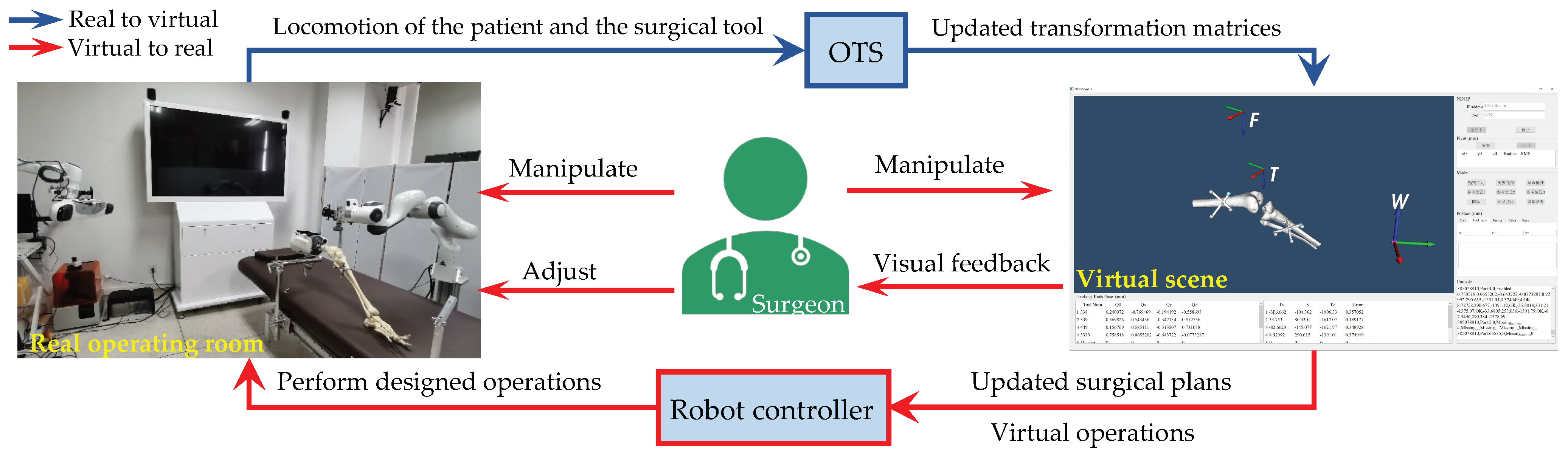
2. Materials and Methods

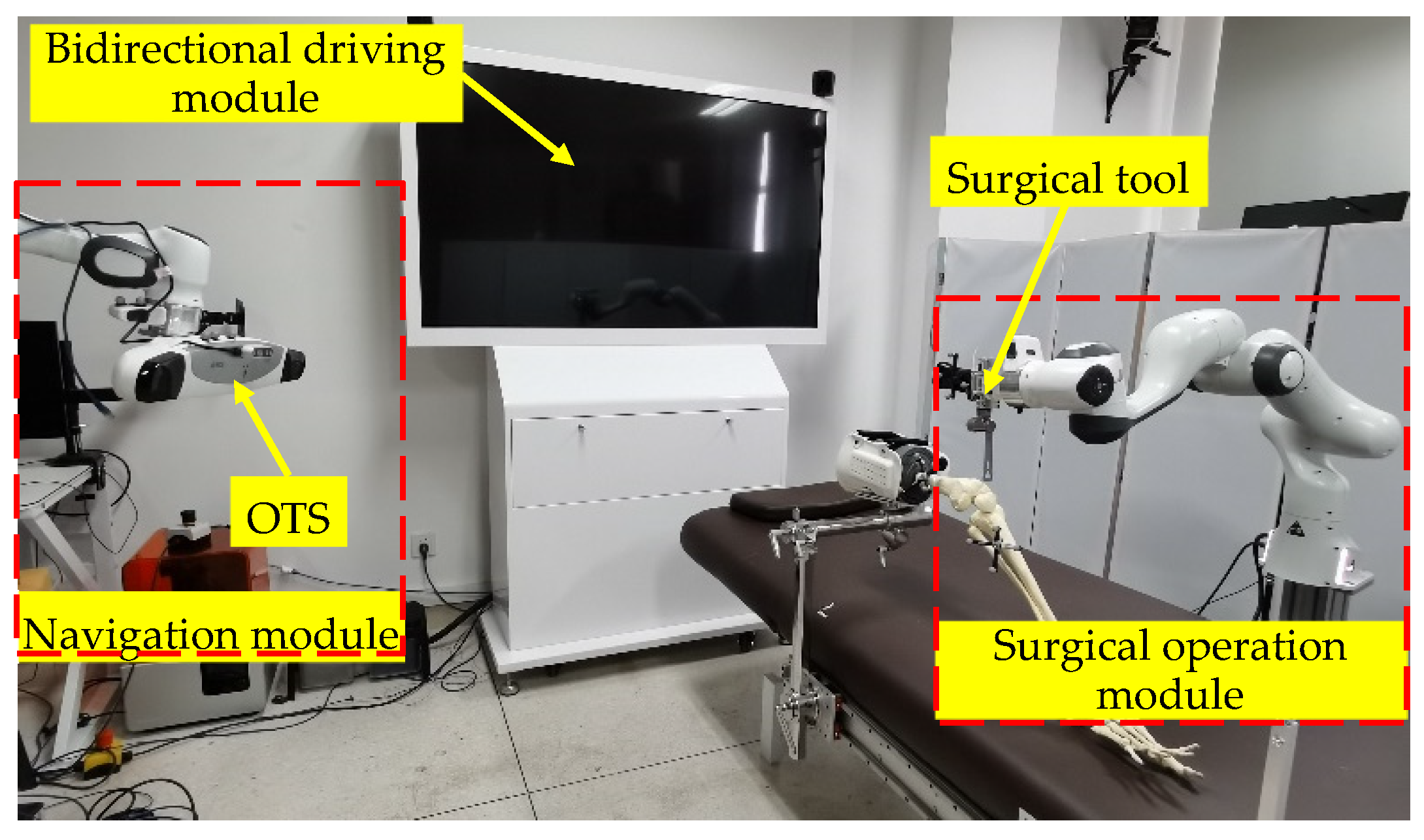
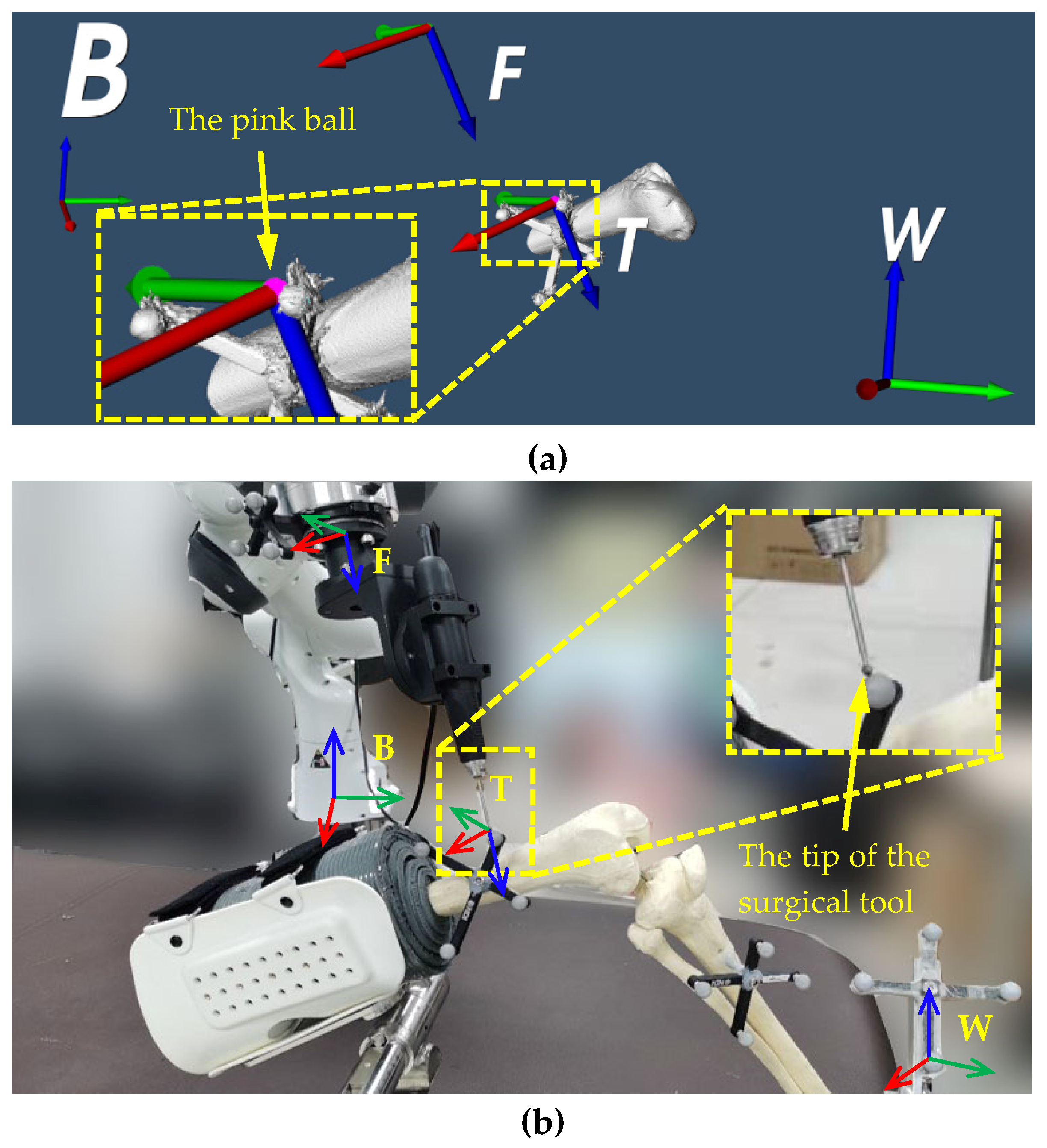
2.1. Universal Robotic Surgery System Orthopedic Surgeries

This paper proposes a dual-robot system for orthopedic surgeries. Different from the conventional surgical robot system, an additional navigation robot is introduced to dynamically adjust the pose of the OTS during surgery, i.e., active navigation. The accuracy of the OTS is influenced by the observation pose of the OTS to its targets. For the multiple targets utilized in orthopedic surgeries, it is important to find the optimal pose of the OTS so as to guarantee the navigation accuracy of all the targets. In addition, the surgeon, the staff, and the medical instruments might block the sight of the OTS if it is stationary. With the help of the navigation robot, the OTS can be adjusted before the occlusion occurs, thus guaranteeing consistent navigation throughout the surgery.
The proposed robotic surgery system mainly includes a navigation module, a surgical operation module, and a bidirectional driving module. The navigation module includes an OTS mounted on the flange of an active navigation robot. The surgical operation module includes the surgical tools mounted on the flange of an operation robot. The bidirectional driving module mainly includes a large screen and a host PC for data and image processing and transmitting.
As shown in Figure 2, the universal robotic surgery system prototype is developed for knee surgeries. Two 7-degree-of-freedom (7-DOF) robots (Model Panda from Franka Emika) are used as the operation and navigation robots. A medical oscillating saw (Model JT-II from BAIDE) is used as the surgical tool. The OTS (Model Polaris Vega from NDI) is used to construct the navigation module. The bidirectional driving module is developed using C++ and VTK (The Visualization Toolkit) library on the Windows platform.
In the navigation module, the OTS is used to define the coordinate system of the surgical site, and the navigation robot is used to adjust the pose of the OTS when necessary. In the surgical operation module, different surgical tools can be mounted on the flange of the operation robot for different surgeries. Preoperative calibration is necessary to calibrate the parameters of the overall system, e.g., the transformation relationships among the robot and its flange, the tracked tool, and the tip of the surgical tool. Thus, the surgical tool can be precisely positioned to the predefined location. In the bidirectional driving module, a host PC dynamically monitors the changes of the operating room via the navigation module, and a large screen is used to display the digital twin of the operation site. When the position and orientation of an object in the operating room change, the virtual scene can be automatically updated. During surgery, if the virtual patient or the virtual surgical tool is manipulated by the operator, this information can also be sent to the surgeon or the operation robot such that the patient and surgical tool in the operating room can follow the virtual models.
During robotic surgery, tracked tools are fixed on the patient’s joint, the surgical tool, etc. The OTS is used to obtain the pose information of the tracked tools in the OTS coordinate system {OT}. A global coordinate system {W} is defined as the base coordinate system of the operating room and the virtual scene. The coordinate system of the preoperative CT image is defined as {CT}. The coordinate systems of the tracked tools in the images are defined as {JTn}. The base coordinate system of the operation robot is defined as {Base}, and its flange coordinate system is defined as {Flange}, and the tracked tool coordinate system on the robot is defined as {RT}. The coordinate system of the surgical tool is defined as {Tool}, and its origin locates at the tip.

2.2. Bidirectional Driving Method

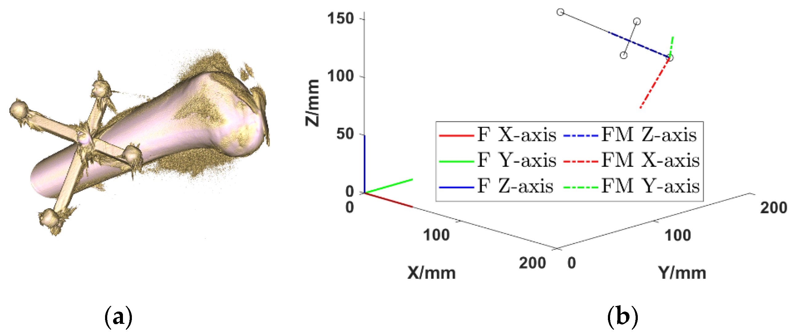
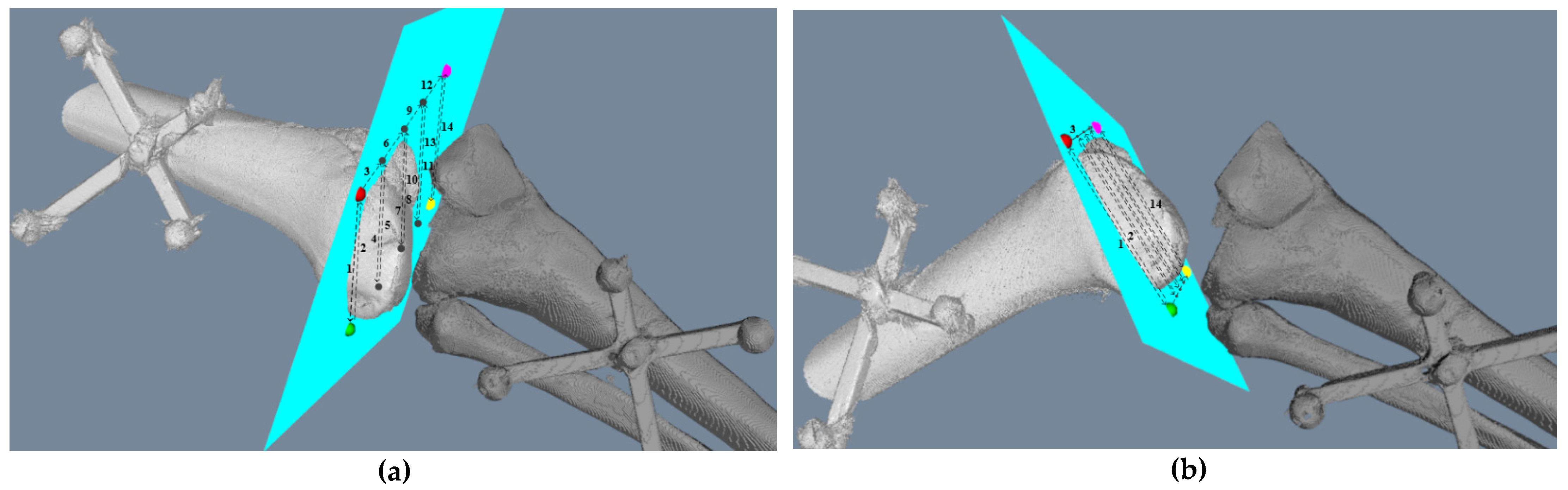
2.2.1. Intraoperative Registration

Registration is a necessary step to derive the positions and orientations of the patient’s joint and the surgical tool via the measurements of the tracked tools. Both the marker-based and marker-free registrations can be implemented for the registration.
Marker-based registration can provide a high-precision registration, which is beneficial to improving the accuracy of the overall system. However, the implant of the markers introduces extra injury to the patient’s bones. The marker-based registration proceeds as follows: First, a data set containing images of both the patient’s joint and the tracked tool is obtained. The marker balls on the tracked tool are visible in both the CT images and the OTS, whose center points are used for the registration. The transformation matrix (TM) between {CT} and {JTn} can be expressed as J T n C T T. J T n W T is known, and thus the TM between {CT} and {W} can be derived using
T C T W = T J T n W T J T n C T 1 = T J T n W T C T J T n
In order to obtain a dynamic digital twin of the patient’s joint, the joint is decoupled to separate bones. Each bone is loaded into the virtual scene separately, and the above registration is repeated. Therefore, the digital twin of the patient’s joint can be dynamically updated according to the measurements of the tracked tools fixed to the bones of the patient’s joint.
If marker-based registration is not applicable, marker-free registration can be implemented instead. The advantage of marker-free registration is that no markers are implanted into the patient’s bone during the CT scanning, whereas the registration accuracy is slightly lower than marker-based registration. In marker-free registration, the point cloud of the patient’s joint is obtained from the CT images. During surgery, after the joint is exposed, a probe of the OTS can be used to obtain the point cloud of the bone surface. These two sets of point clouds can be utilized for registration. The relationship of {CT} and {W} can be calculated using the N-point registration method. After registration, the joints in the CT images can be aligned to the operation site.
Similarly, the relationship between the tracked tool and the tip of the surgical tool needs to be calibrated and registered. This TM can be calculated using
T T o o l B a s e = T F l a n g e B a s e T R T F l a n g e T T o o l R T
where F l a n g e B a s e T is the TM between the robot base and the flange, R T F l a n g e T is the TM between the flange and the tracked tool, and T o o l R T T is the TM between the tip of the surgical tool and the tracked tool. F l a n g e B a s e T is available in the operation robot’s firmware, R T F l a n g e T can be calibrated using the classic eye-to-hand calibration algorithm [41], and T o o l R T T can be measured using the probe of the OTS.
In addition, according to the above equation, R T B a s e T can also be calculated. Since the OTS locates the tracked tool at the end of the robot, R T W T can be calculated by the world coordinate system and the tracked tool at the flange of the robot. The representation of the robot base in the world coordinate system is obtained.
T B a s e W = T R T W T B a s e R T = T R T W T R T B a s e 1
According to the known TMs, the representation of the tool coordinate system in the world coordinate system can be obtained using
T T o o l W = T B a s e W T T o o l B a s e
Based on the above TMs, the virtual objects can be dynamically updated via the measurements from the OTS. Therefore, the connections between the real and virtual are established.
The effectiveness of the proposed method is tested on the developed robotic surgery system prototype. For TKA, based on our previous work [42], the registration of the phantom’s femoral and tibia proceeds as follows: Firstly, both the phantom and the tracked tools are scanned to obtain the CT images. Secondly, the femur and tibia images are decoupled into two data sets and labeled separately. Figure 3a shows the reconstructed femur model. During the operation, the OTS observes the tracked tools and aligns the preoperative CT images. The registration result is shown in Figure 3b, and the registration accuracy is below 0.1 mm, as is shown in Table 1.
The desired trajectory in the world coordinate system {W} should be transformed into the base coordinate system of the operation robot {Base}. Therefore, it is necessary to calibrate {W} and {Base}. In the experiment, the OTS is used as the position and orientation feedback. The robot forward kinematics is known. In the developed prototype system, the TM between {Base} and {W} is calibrated and given as follows:
T W B a s e 1 = T N D I B a s e 1 T W N D I 1 = [ 0 . 73386 0 . 030063 0 . 67863 943 . 75 0 . 026655 0 . 99953 0 . 015454 786 . 47 0 . 67878 0 . 0067475 0 . 73431 245 . 34 0 0 0 1 ]
The transformation relationship between the flange and the tracked tool on the surgical tool also needs to be calibrated. The same method is used for this calibration with the help of the OTS and the probe. The obtained TMs are shown in the following equations.
T R T F l a n g e 1 = [ 0 . 7742 0 . 4966 0 . 3925 68 . 2000 0 . 6326 0 . 5864 0 . 5059 40 . 5000 0 . 0211 0 . 6400 0 . 7681 16 . 4000 0 0 0 1 ]
T T o o l R T 1 = [ 0 . 7742 0 . 6326 0 . 0211 89 . 0500 0 . 4966 0 . 5864 0 . 6399 96 . 0700 0 . 3925 0 . 5060 0 . 7681 275 . 0600 0 0 0 1 ]

2.2.2. Real to Virtual Mapping

During the joint surgeries, the patient’s joint needs to be moved to several different poses so as to facilitate the specific operations. The TKA is selected as an example of real to virtual mapping. As shown in Figure 4a–c, the position of the patient’s knee joint needs to be adjusted so as to facilitate the oscillating saw’s cutting. The OTS captures the locomotion of the femur and tibia and sends the measurements to the host PC to drive the virtual femur and tibia. In this manner, the synchronization between the real and the virtual is realized.
The preoperative images are used to build the 3D model of the patient’s joint in the virtual scene. The position information is the representation of the tracked tool {JTn} under the OTS {OT}, which can be expressed using J T n O T T. The world coordinate system {W} is located on the operating table. Its representation is also expressed under the OTS {OT}, i.e., W O T T. The inverse transformation of the TM is used to obtain the representation in the world coordinate system {W}, as shown below:
T O T W = T W O T 1
According to Equation (8), each tracked tool can be represented in {W}. For example, {JTn} relative to {W} can be expressed as J T n W T by Equation (9). The OTS also obtains the position of the tracked tool on the robot, which is denoted as R T W T.
T J T n W = T O T W T J T n O T
In order to evaluate the accuracy of the real to virtual mapping, a pink ball is placed at the tip of the surgical tool, which is defined as the origin of the surgical tool coordinate system. Subsequently, the tip of the surgical tool is moved towards the marker ball on the tracked tool of the femur, as shown in Figure 5b. The surgical tool is moved until the tip touches the surface of the marker ball. Based on the feedback of the OTS, the pink ball in the virtual scene also touched the surface of the marker ball. This validates the calibration and registration of the robotic surgical system.

2.2.3. Virtual to Real Mapping

In this paper, the manipulations on the virtual objects can also be used to drive the operation robot and to provide visual guidance to the surgeon during the manual adjustment of the joint. The virtual to real mapping can be mainly divided into the following two parts:
Virtual manipulation on the operation robot: Prior to operation, the surgical tool is placed in the initial position. During operation, it is inevitable that the surgical tool will be moved to several different locations to cut the bone along different planes. However, the space around the operation table is crowded. If the surgical tool is directly manipulated by the surgeon or moved by the operation robot, the surgical tool or the operation robot may cause injuries to the patient, the surgeon, or the intraoperative devices. Instead, the surgeon can manipulate the virtual surgical tool and carefully verify the safety of operation in the virtual scene. Subsequently, the position and orientation information of the verified safe operation in the virtual scene is extracted and sent to the operation robot so that it can move the surgical tool to its destination.
Visual guidance for the adjustment of the patient’s joint: The virtual to real mapping can also be used to assist the surgeon in the adjustment of the patient’s joint by providing a visual guidance. In some surgeries, such as TKA, the surgeon must move the patient’s knee joint to several different positions to facilitate the bone cutting. In preoperative planning, the desired positions of the patient’s joint and the surgical tool at different operation stages can be specified. During the surgery, both the current position of the patient’s joint and its destination are displayed on the screen. With the help of the visual guidance, the surgeon can easily move the joint to the correct position.

3. Results

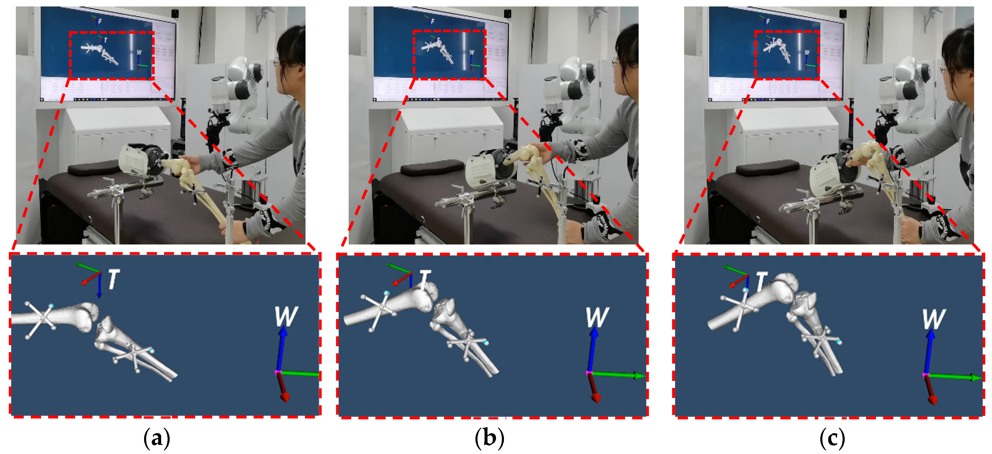
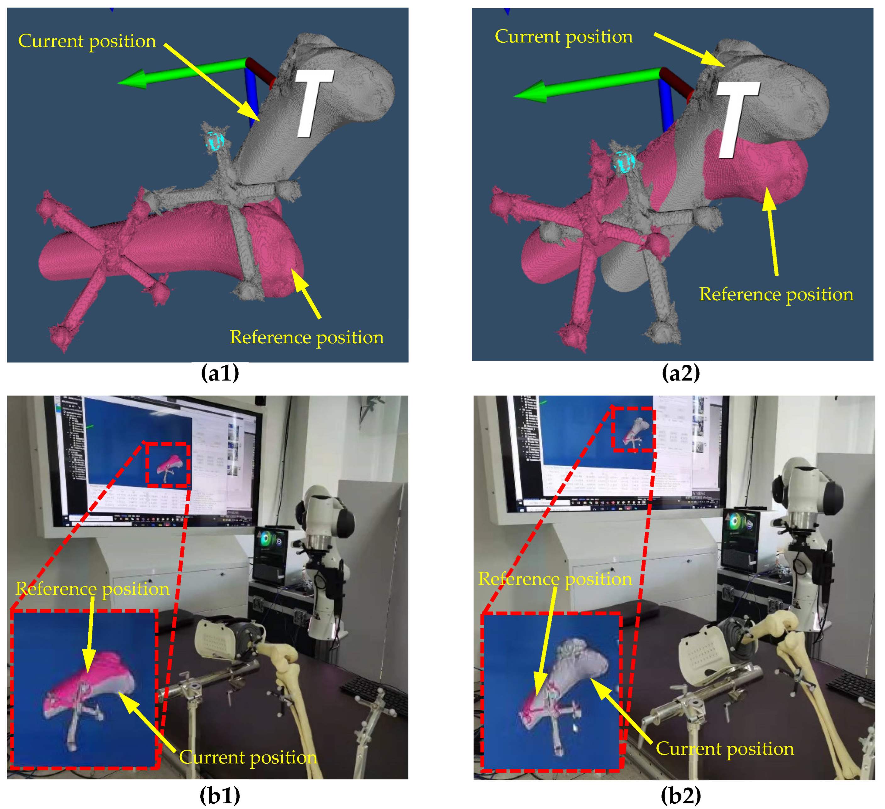
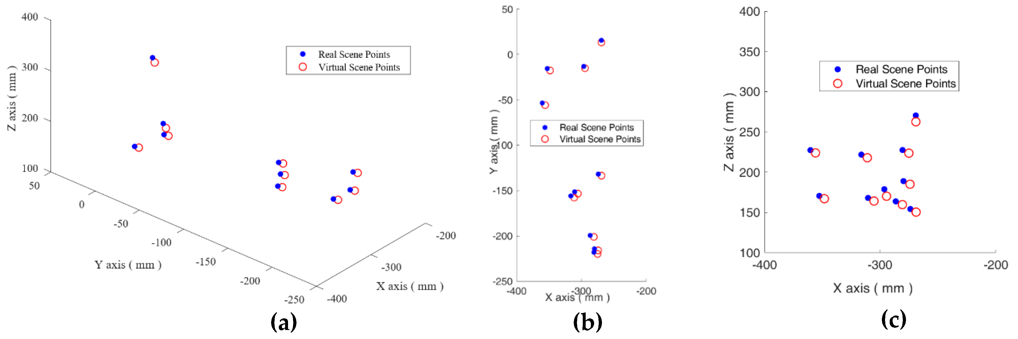
3.1. The Real to Virtual Mapping

For the real to virtual mapping, a lower limb phantom is used to simulate the patient’s femur and tibia. Before the experiment, a tracked tool is rigidly connected to the surgical tool so as to provide position and orientation feedback. For TKA, two tracked tools are fixed on the phantom’s femoral and the tibia separately. The tracked tools fixed on the phantom can be used in the registration.
The 3D models of the phantom’s femur and tibia are loaded into the virtual scene. When the phantom is adjusted, the relationship between the two bones changes. The virtual models also change accordingly. In order to facilitate the observation of the movement of the model, some important reference coordinate systems are displayed in the virtual scene, as shown in Figure 4a. When the position of the femur is continuously adjusted, it can be observed that the virtual femur model can well reproduce the locomotion of the real femur. The results of the experiment are shown in Figure 4b,c.
In order to evaluate the accuracy of the real to virtual mapping, the tip of the surgical tool is placed at 10 different positions. Figure 6 shows these points in the world coordinate system. The blue dots represent the points in the real operation site, and the red circles represent the points in the virtual scene. It can be found that the error of the real to virtual mapping is on the order of 1–2 mm, as shown in Table 2. The average error is calculated to be 1.723 mm.
The cutting paths of the surgical tool are preoperatively planned in the {CT} coordinate system. Figure 7a shows the surgical plan when the knee joint is flattened, where the blue plane is the planned cutting plane and the segments 1–14 are the planned cutting paths. During surgery, if the surgeon adjusts the pose of the knee joint, the planned cutting paths should follow the movement of the knee joint, or mismatch will occur. Since the joint is decoupled, in real to virtual mapping, the system can achieve synchronization of the planned cutting paths during the surgery. As shown in Figure 7b, when the knee joint is bent to a different pose, the preoperatively planned cutting paths can be dynamically updated. This can guarantee that the surgical robot can always move the surgical tool to the correct position and precisely complete the surgical plan after the surgeon adjusts the joint.

3.2. The Virtual to Real Mapping

The adjustment of the knee joint in TKA is adopted to evaluate the virtual to real mapping. The cutting of the femur is selected as an example. In preoperative planning, for each cutting plane, the desired pose of the joint is specified. As shown in Figure 8(a1,a2), during intraoperative operation, both the reference position (marked in pink color) and the current position (marked in grey color) of the femur are displayed on the screen. In this manner, the difference between the current position and its destination can be intuitively shown to the surgeon. Subsequently, the surgeon adjusts the knee joint with the visual guidance. Figure 8(b1,b2) shows the knee joint after adjustment, where the insets show the relationship of the actual knee joint position and the reference position. It can be observed that the knee joint almost coincides with the references. The surgeon does not have to adjust the knee joint to exactly coincide with the reference position. The operation robot can move the surgical tool to the correct position, as the real operation site and the virtual scene are synchronized. This helps to reduce the requirements on the surgeon’s experiences in the adjustment of the patient’s joint.
To evaluate the virtual manipulation of the operation robot, the relationship between the patient’s knee and each coordinate system is registered and calibrated preoperatively. As shown in Figure 9, the virtual knee model and all the coordinate systems are loaded into the virtual scene. The virtual surgical tool coordinate system is represented as a point. The preoperatively defined trajectories of the surgical tool’s tip can be loaded into the virtual scene. Alternately, the surgeon can also directly manipulate the virtual surgical tool to set a desired trajectory for the virtual tool. The position and orientation information of the virtual surgical tool in the virtual scene is sent to the host. The developed system calculates the related position in the {Base} to guide the operation robot in the real operating room. As shown in Figure 9a, a standby position is defined for the surgical tool in the virtual scene. Subsequently, the real surgical tool is moved to this standby position by the operation robot.
Similarly, in order to evaluate the accuracy of the virtual to real mapping, 10 different points are assigned in the virtual scene for the tip of the surgical tool. Subsequently, the locations of these 10 points are sent to the operation robot so as to move the real surgical tool’s tip to the defined points. Figure 10a shows the positions of the virtual points (red circles) and the actual points (blue dots). There exist small discrepancies between the virtual and real points. Table 3 shows the numeric assessment of all the errors for each point. The average error is found to be 7.052 mm.

4. Discussion

Many existing VR and AR methods can also provide promising results. The current state of the art in real to virtual mapping can achieve high-precision, real-time monitoring intraoperatively. In virtual to real mapping, many virtual surgical systems use haptic devices to simulate the surgery for the training of surgeons. These methods can be defined as unidirectional mapping, where the synchronization between the real objects and the virtual models is not pursued. However, for joint surgeries, this unidirectional mapping is not adequate because the pose of the patient’s joint might be adjusted. In this “dynamic” scenario, it is necessary to synchronize the real operation site and its digital twin. Therefore, the proposed bidirectional mapping is an enabling technique for the synchronization between the real operation site and its digital twin. On the one hand, it is necessary to dynamically update the virtual joint to the real joint such that the preoperatively planned trajectories of the surgical robot can be dynamically updated so as to match the locomotion of the joint. On the other hand, it is also necessary that the preoperatively defined adjustments of the joint or the manipulations on the virtual models can be directly sent back to the surgeon or to the surgical robot so as to improve the efficiency.
Experimental results have shown that the synchronization between the real operation site and its digital twin has been realized. However, the registration accuracy of the overall system needs to be further improved.
In the real to virtual mapping, the registration accuracy is found to be around 1.723 mm. The RMS error of the OTS used in this paper is on the sub-millimeter magnitude. The calibration used in the real to virtual mapping is the TM of T o o l R T T. In calibration, a probe is used to locate the tip of the surgical tool in {RT}. As a result, the majority of the error might come from the inaccuracy in the manual alignment of the probe’s axis to the surgical tool.
For the virtual to real mapping, several points in the virtual scene are selected as destinations. The information is sent to the operation robot so that the operation robot can move the tip of the surgical tool to the destinations. The average error in the virtual to real mapping is found to be 7.052 mm, which is relatively large. Similar to the real to virtual mapping, the inaccuracy of the manual alignment of the probe’s axis to the surgical tool will be included. The calibration errors of F l a n g e R T T and B a s e W T will also be included in the virtual to real mapping. In addition, for the operation robot, sub-millimeter repeatability has been realized, whereas the rigorous calibration of its DH parameters has not been carried out. The nominal kinematics is adopted during the calibration and registration. This might increase the calibration error of the overall system.

5. Conclusions

For the safety of robotic orthopedic surgeries, it is important to dynamically monitor the locomotion of the patient and the surgical tool and synchronize the operations in the real operation site and its virtual model. This paper presents a virtual and real bidirectional driving system, where the dynamic digital twin of the patient’s joint is established from the operative CT images. The patient’s joint is decoupled into separate bones and the intraoperative OTS is used for the dynamic update of the pose of the joint and the surgical tool.
In the developed system, the adjustments and locomotion of the joint can be dynamically updated in the virtual scene such that the preoperative surgery plan can always match the dynamic variations of the joint during surgery. The updated surgery plan and the manipulations on the virtual models can then be re-projected to the operation robot and the surgeon, enabling highly intuitive and efficient human–computer interactions.
For the virtual to real mapping, the preoperatively defined poses for the patient’s joint and the trajectories for the surgical tool can be loaded into the virtual scene. The surgeon can also directly manipulate the virtual surgical tool instead of the real surgical tool. All the preoperatively defined trajectories and the intraoperative manipulation on the virtual objects can be used to drive the real operation robot in the manipulation of the surgical tool. In addition, the system can provide visual guidance for the surgeon in the adjustment of the patient’s joint, especially for joint surgeries.
TKA is adopted as the typical orthopedic surgery. Tests are conducted on lower limb phantoms. Experimental results show that the developed system can realize the synchronization between the real operating room and the virtual scene. Therefore, the developed bidirectional driving system is feasible for robotic orthopedic surgeries.
In the future work, more efforts will be directed towards the improvement of the registration and calibration accuracy of the overall system, where the influence of the robot’s kinematics, the registration method, and the OTS will be systematically investigated. In addition, more experimental verifications will be conducted to fully test the precision, capability, and feasibility of the developed system in completing orthopedic surgeries.

Author Contributions

Conceptualization, Y.Q., M.M., H.W., L.S. and J.H.; methodology, Y.Q., M.M., H.W., L.S. and J.H.; experimentation, M.M.; writing—original draft preparation, Y.Q., M.M. and H.W.; writing—review and editing, Y.Q., H.W. and J.H.; supervision, Y.Q. and H.W.; project administration, Y.Q. and H.W.; funding acquisition, Y.Q., H.W. and J.H. All authors have read and agreed to the published version of the manuscript.

Funding

This work was supported in part by National Key R&D Program of China (No. 2018YFB1307601), and in part by National Natural Science Foundation of China (Nos. 61873133, U1913208, 61873135, and 52005270), and in part by the Natural Science Foundation of Tianjin (No.21JCZDJC00090).

Informed Consent Statement

Informed consent was obtained from all subjects involved in the study.

Conflicts of Interest

The authors declare no conflict of interest.

References

  1. He, Y.; Zhao, B.; Qi, X.; Li, S.; Yang, Y.; Hu, Y. Automatic Surgical Field of View Control in Robot-Assisted Nasal Surgery. IEEE Robot. Autom. Lett. 2021, 6, 247–254. [Google Scholar] [CrossRef]
  2. Li, S.; Du, Z.; Yu, H. A Robot-Assisted Spine Surgery System Based on Intraoperative 2D Fluoroscopy Navigation. IEEE Access 2020, 8, 51786–51802. [Google Scholar] [CrossRef]
  3. Ma, Q.; Kobayashi, E.; Suenaga, H.; Hara, K.; Wang, J.; Nakagawa, K.; Sakuma, I.; Masamune, K. Autonomous Surgical Robot with Camera-Based Markerless Navigation for Oral and Maxillofacial Surgery. IEEE/ASME Trans. Mechatron. 2020, 25, 1084–1094. [Google Scholar] [CrossRef]
  4. Naik, A.; Smith, A.D.; Shaffer, A.; Krist, D.T.; Moawad, C.M.; MacInnis, B.R.; Teal, K.; Hassaneen, W.; Arnold, P.M. Evaluating robotic pedicle screw placement against conventional modalities: A systematic review and network meta-analysis. Neurosurg. Focus 2022, 52, E10. [Google Scholar] [CrossRef]
  5. Tovar, M.A.; Dowlati, E.; Zhao, D.Y.; Khan, Z.; Pasko, K.B.D.; Sandhu, F.A.; Voyadzis, J.-M. Robot-assisted and augmented reality-assisted spinal instrumentation: A systematic review and meta-analysis of screw accuracy and outcomes over the last decade. J. Neurosurgery Spine 2022, 1, 1–16. [Google Scholar] [CrossRef]
  6. Mehmanesh, H.; Henze, R.; Lange, R. Totally endoscopic mitral valve repair. J. Thorac. Cardiovasc. Surg. 2002, 123, 96–97. [Google Scholar] [CrossRef] [Green Version]
  7. Menon, M.; Tewari, A.; Peabody, J.; Team, V.I.P. Vattikuti Institute prostatectomy: Technique. J. Urol. 2003, 169, 2289–2292. [Google Scholar] [CrossRef]
  8. Mettler, L.; Ibrahim, M.; Jonat, W. One year of experience working with the aid of a robotic assistant (the voice-controlled optic holder AESOP) in gynaecological endoscopic surgery. Hum. Reprod. 1998, 13, 2748–2750. [Google Scholar] [CrossRef] [Green Version]
  9. Asham, K.; Meyers, J.E.; Ioannis, S.; John, P. Next-Generation Robotic Spine Surgery: First Report on Feasibility, Safety, and Learning Curve. Oper. Neurosurg. 2018, 1, 61–69. [Google Scholar]
  10. Mao, G.; Gigliotti, M.J.; Myers, D.; Yu, A.; Whiting, D. A Single Surgeon Direct Comparison of O-arm Neuronavigation versus Mazor X™ Robotic-Guided Posterior Spinal Instrumentation. World Neurosurg. 2020, 137, e278–e285. [Google Scholar] [CrossRef]
  11. Lonjon, N.; Chan-Seng, E.; Costalat, V.; Bonnafoux, B.; Vassal, M.; Boetto, J. Robot-assisted spine surgery: Feasibility study through a prospective case-matched analysis. Eur. Spine J. Off. Publ. Eur. Spine Soc. Eur. Spinal Deform. Soc. Eur. Sect. Cerv. Spine Res. Soc. 2016, 25, 947–955. [Google Scholar] [CrossRef]
  12. Matsen, F.A.; Garbini, J.L.; Sidles, J.A.; Pratt, B.; Baumgarten, D.; Kaiura, R. Robotic Assistance in Orthopaedic Surgery. Clin. Orthop. Relat. Res. 1993, 18, 178–186. [Google Scholar] [CrossRef]
  13. Siebert, W. Technique and first clinical results of robot-assisted total knee replacement. Knee 2002, 9, 173–180. [Google Scholar] [CrossRef]
  14. Roche, M. The MAKO robotic-arm knee arthroplasty system. Arch. Orthop. Trauma Surg. 2021, 141, 2043–2047. [Google Scholar] [CrossRef]
  15. Sires, J.D.; Craik, J.D.; Wilson, C.J. Accuracy of bone resection in MAKO total knee robotic-assisted surgery. J. Knee Surg. 2021, 34, 745–748. [Google Scholar] [CrossRef]
  16. Andreas, W.; Adrian, M.; Werner, N. Development of a Real-Time Virtual Reality Environment for Visualization of Fully Digital Microscope Datasets. In Proceedings of the Advanced Biomedical and Clinical Diagnostic and Surgical Guidance Systems XVII, San Francisco, CA, USA, 26 February 2019. [Google Scholar]
  17. Hernigou, P.; Olejnik, R.; Safar, A.; Martinov, S.; Hernigou, J.; Ferre, B. Digital twins, artificial intelligence, and machine learning technology to identify a real personalized motion axis of the tibiotalar joint for robotics in total ankle arthroplasty. Int. Orthop. 2021, 45, 2209–2217. [Google Scholar] [CrossRef]
  18. Hernigou, P.; Scarlat, M.M. Ankle and foot surgery: From arthrodesis to arthroplasty, three dimensional printing, sensors, artificial intelligence, machine learning technology, digital twins, and cell therapy. Int. Orthop. 2021, 45, 2173–2176. [Google Scholar] [CrossRef]
  19. Ahmed, H.; Devoto, L. The Potential of a Digital Twin in Surgery. Surg. Innov. 2021, 28, 509–510. [Google Scholar] [CrossRef]
  20. Abdallah, M.B.; Blonski, M.; Wantz-Mezieres, S.; Gaudeau, Y.; Taillandier, L.; Moureaux, J.M.; Darlix, A.; de Champfleur, N.M.; Duffau, H. Data-Driven Predictive Models of Diffuse Low-Grade Gliomas Under Chemotherapy. IEEE J. Biomed. Health Inf. 2019, 23, 38–46. [Google Scholar] [CrossRef]
  21. Baumgarten, C.; Zhao, Y.; Sauleau, P.; Malrain, C.; Jannin, P.; Haegelen, C. Improvement of Pyramidal Tract Side Effect Prediction Using a Data-Driven Method in Subthalamic Stimulation. IEEE Trans. Biomed. Eng. 2017, 64, 2134–2141. [Google Scholar] [CrossRef]
  22. Tsang-Hsiang, C.; Hu, P.J.H. A Data-Driven Approach to Manage the Length of Stay for Appendectomy Patients. IEEE Trans. Syst. Man Cybern. Part A Syst. Hum. 2009, 39, 1339–1347. [Google Scholar] [CrossRef]
  23. Ayoub, A.; Pulijala, Y. The application of virtual reality and augmented reality in Oral & Maxillofacial Surgery. BMC Oral Health 2019, 19, 238. [Google Scholar]
  24. Hanken, H.; Schablowsky, C.; Smeets, R.; Heiland, M.; Sehner, S.; Riecke, B.; Nourwali, I.; Vorwig, O.; Gröbe, A.; Al-Dam, A. Virtual planning of complex head and neck reconstruction results in satisfactory match between real outcomes and virtual models. Clin. Oral Investig. 2015, 19, 647–656. [Google Scholar] [CrossRef]
  25. Myers, B.; Nahal, J.A.; Yang, C.; Brown, L.; Ghiasi, S.; Knoesen, A. Towards data-driven pre-operative evaluation of lung cancer patients: The case of smart mask. In Proceedings of the 2016 IEEE Wireless Health, Bethesda, MD, USA, 25–27 October 2016; pp. 1–6. [Google Scholar]
  26. Budilovsky, O.; Alipour, G.; Knoesen, A.; Brown, L.; Ghiasi, S. A data-driven approach to pre-operative evaluation of lung cancer patients. In Proceedings of the 2017 IEEE 19th International Conference on e-Health Networking, Applications and Services, Dalian, China, 12–15 October 2017; pp. 1–6. [Google Scholar]
  27. Gamage, P.; Xie, S.Q.; Delmas, P.; Xu, P. Pose estimation of femur fracture segments for image guided orthopedic surgery. In Proceedings of the 2009 24th International Conference Image and Vision Computing, Wellington, New Zealand, 23–25 November 2009; pp. 288–292. [Google Scholar]
  28. Gamage, P.; Xie, S.Q.; Delmas, P.; Xu, P.; Mukherjee, S. Intra-operative 3D pose estimation of fractured bone segments for image guided orthopedic surgery. In Proceedings of the 2008 IEEE International Conference on Robotics and Biomimetics, Bangkok, Thailand, 22–25 February 2009; pp. 288–293. [Google Scholar]
  29. Hagenah, J.; Evers, T.; Scharfschwerdt, M.; Schweikard, A.; Ernst, F. A Support Vector Regression-Based Data-Driven Leaflet Modeling Approach for Personalized Aortic Valve Prosthesis Development. In Proceedings of the 2018 Computing in Cardiology Conference, Maastricht, The Netherlands, 23–26 September 2018. [Google Scholar]
  30. Pardo, A.; Streeter, S.S.; Maloney, B.W.; Gutierrez-Gutierrez, J.A.; McClatchy, D.M.; Wells, W.A.; Paulsen, K.D.; Lopez-Higuera, J.M.; Pogue, B.W.; Conde, O.M. Modeling and Synthesis of Breast Cancer Optical Property Signatures with Generative Models. IEEE Trans. Med. Imaging 2021, 40, 1687–1701. [Google Scholar] [CrossRef]
  31. Peng, H.; Yang, X.; Su, Y.H.; Hannaford, B. Real-time Data Driven Precision Estimator for RAVEN-II Surgical Robot End Effector Position. In Proceedings of the 2020 IEEE International Conference on Robotics and Automation, Paris, France, 31 May–31 August 2020; pp. 350–356. [Google Scholar]
  32. Haigron, P.; Bellemare, M.E.; Acosta, O.; Goksu, C.; Kulik, C.; Rioual, K.; Lucas, A. Depth-map-based scene analysis for active navigation in virtual angioscopy. IEEE Trans. Med. Imaging 2004, 23, 1380–1390. [Google Scholar] [CrossRef]
  33. Moccia, S.; Wirkert, S.J.; Kenngott, H.; Vemuri, A.S.; Apitz, M.; Mayer, B.; De Momi, E.; Mattos, L.S.; Maier-Hein, L. Uncertainty-Aware Organ Classification for Surgical Data Science Applications in Laparoscopy. IEEE Trans. Biomed. Eng. 2018, 65, 2649–2659. [Google Scholar] [CrossRef] [Green Version]
  34. Sefati, S.; Gao, C.; Iordachita, I.; Taylor, R.H.; Armand, M. Data-Driven Shape Sensing of a Surgical Continuum Manipulator Using an Uncalibrated Fiber Bragg Grating Sensor. IEEE Sens. J. 2021, 21, 3066–3076. [Google Scholar] [CrossRef]
  35. Jiang, W.; Yu, T.; He, X.; Yang, Y.; Wang, Z.; Liu, H. Data-Driven Modeling the Nonlinear Backlash of Steerable Endoscope Under a Large Deflection Cannulation in ERCP Surgery. In Proceedings of the 2021 IEEE International Conference on Real-time Computing and Robotics, Xining, China, 15–19 July 2021; pp. 39–44. [Google Scholar]
  36. Nercessian, M.; Haouchine, N.; Juvekar, P.; Frisken, S.; Golby, A. Deep Cortical Vessel Segmentation Driven By Data Augmentation with Neural Image Analogy. In Proceedings of the 2021 IEEE 18th International Symposium on Biomedical Imaging, Nice, France, 13–16 April 2021; pp. 721–724. [Google Scholar]
  37. Mamone, V.; Ferrari, V.; Condino, S.; Cutolo, F. Projected Augmented Reality to Drive Osteotomy Surgery: Implementation and Comparison with Video See-Through Technology. IEEE Access 2020, 8, 169024–169035. [Google Scholar] [CrossRef]
  38. Suthakorn, J. A concept on Cooperative Tele-Surgical System based on Image-Guiding and robotic technology. In Proceedings of the 2012 Pan American Health Care Exchanges, Miami, FL, USA, 26–31 March 2012; pp. 41–45. [Google Scholar]
  39. Guo, J.; Feng, S.; Guo, S. Study on the Automatic Surgical Method of the Vascular Interventional Surgical Robot Based on Deep Learning. In Proceedings of the 2021 IEEE International Conference on Mechatronics and Automation, Takamatsu, Japan, 8–11 August 2021; pp. 1076–1081. [Google Scholar]
  40. Li, Y.; Miyasaka, M.; Haghighipanah, M.; Lei, C.; Hannaford, B. Dynamic modeling of cable driven elongated surgical instruments for sensorless grip force estimation. In Proceedings of the 2016 IEEE International Conference on Robotics and Automation, Stockholm, Sweden, 16–21 May 2016; pp. 4128–4134. [Google Scholar]
  41. Tsai, R.Y. A New Technique for Fully Autonomous and Efficient 3D Robotics Hand/Eye Calibration. IEEE Trans. Robot. Autom. 1989, 5, 345–358. [Google Scholar] [CrossRef] [Green Version]
  42. Qin, Y.; Ma, M.; Shen, L.; Song, Z.; Chen, X.; Wang, H. Pre- and Intra-operative Dynamic Registration for Total Knee Arthroplasty Based on CT Image Annotation. In Proceedings of the 2021 IEEE International Conference on Robotics and Biomimetics, Sanya, China, 27–31 December 2021. [Google Scholar]
Figure 1. The framework of the proposed virtual and real bidirectional driving system. The OTS is very important as it dynamically monitors the locomotion of the patient and the surgical tool. The measurements are then used to update the virtual scene and also the preoperative surgical plans. Different from master-slave type robotic surgery systems, the surgeon does not have to finish the surgery on the haptic device. Instead, the surgeon can supervise the overall system and make necessary interventions, such as the adjustment of the patient’s joint or the manipulations in the real or virtual scenes.
Machines 10 00530 g001
Figure 2. Developed robotic surgery system prototype for knee surgeries.
Machines 10 00530 g002
Figure 3. Intraoperative registration results: (a) the reconstructed 3D femur model, (b) the femoral coordinate system {F} (solid line), and the marker coordinate system {FM} (dotted line) are registered and aligned.
Machines 10 00530 g003
Figure 4. Real to virtual mapping. When the knee joint is adjusted by the surgeon, the locomotion information is captured by the OTS and used to drive the virtual femur and tibia. (a) knee in extension, (b) knee in semi-flexion, and (c) knee in flexion.
Machines 10 00530 g004
Figure 5. Real to virtual mapping: (a) the virtual scene showing the virtual femur model and the related coordinate systems; (b) the real operation site showing the tip of the surgical tool touches the surface of the marker ball on the tracked tool. The virtual femur and the coordinate systems in the virtual scene are aligned to the real operation site.
Machines 10 00530 g005
Figure 6. The real to virtual mapping: (a) the tip positions of the surgical tool in the virtual scene and the real operation site. The projection of points on the (b) X–Y plane and (c) X–Z plane.
Machines 10 00530 g006
Figure 7. The preoperatively planned surgical path is loaded in the virtual scene of the system. When the pose of the knee joint changes: (a) the knee joint is flattened, and (b) the knee joint is bent, the cutting paths in the virtual scene can be dynamically updated.
Machines 10 00530 g007
Figure 8. The visual guidance used to guide the surgeon when adjusting the knee joint: (a1,a2) the two desired poses of the femur in intraoperative bone cutting (shown in pink color) and the current position of the femur (shown in grey color); (b1,b2) the manual adjustment of the femur showing that the femur can be easily moved to the neighborhood of the reference position.
Machines 10 00530 g008
Figure 9. The standby position selected by the surgeon in the virtual scene is used to move the surgical robot in the real scene. (a) Various important coordinate systems in virtual scene, (b) the real operating scene, and the corresponding coordinate systems.
Machines 10 00530 g009
Figure 10. The virtual to real mapping: the positions of the tip of the surgical tool (a) in the virtual scene and the operation site. The projection of points on the (b) X–Y plane, and (c) X–Z plane.
Machines 10 00530 g010
Table 1. The distance error (unit: mm).
DistanceGround-TruthCalculatedError
A-C88.0087.990.01
A-B50.0050.070.07
A-D60.0059.960.04
Table 2. Ten positions of the surgical tool in the virtual and real scenes and the errors. (Unit: mm).
Group IDCoordinates of the PointsErrorGroup IDCoordinates of the PointsError
xyzxyz
1−239.613−418.146342.4102.0746−169.222−459.504333.8561.556
−239.347−416.181341.804−168.376−458.199333.909
2−57.909−392.23754.3540.7967−154.900−531.637474.2821.653
−58.599−392.48654.045−155.192−530.049473.930
3−148.851−427.016294.9401.96783.228−498.840196.6620.638
−148.436−426.605293.0623.384−498.817196.044
4−18.036−220.22179.75012.660917.274−585.962138.4102.383
−15.481−219.64779.28417.820−584.000139.648
5−320.424−486.398335.0611.79910−5.848−389.018190.7311.707
−321.172−485.076334.097−7.243−388.035190.715
Table 3. Ten positions of the surgical tool in the virtual and real scenes and the errors. (Unit: mm).
Group IDCoordinates of the PointsErrorGroup IDCoordinates of the PointsError
xyzxyz
1−348.460−17.688166.9695.9516−280.836−201.004159.6127.203
−352.806−15.579170.445−286.582−199.388163.643
2−305.445−153.240164.0606.6777−268.969−133.468150.2786.518
−310.590−151.312167.853−273.956−131.776154.119
3−311.214−157.672217.8236.7288−356.130−55.900223.8976.018
−316.372−155.790221.712−360.498−53.494227.266
4−275.199−219.73223.5326.9559−294.561−15.104170.0079.143
−280.684−217.969227.429−296.504−13.204178.737
5−274.236−215.848184.9397.11910−269.17613.186262.5418.202
−279.947−214.171188.845−269.28015.594270.381
Publisher’s Note: MDPI stays neutral with regard to jurisdictional claims in published maps and institutional affiliations.

