Article

A Computer-Assisted Preoperative Path Planning Method for the Parallel Orthopedic Robot

1
School of Automation, Beijing University of Posts and Telecommunications, Beijing 100876, China
2
School of Artificial Intelligence and Data Science and Engineering Research Center of Intelligent Rehabilitation Device and Detection Technology, Ministry of Education, Hebei University of Technology, Tianjin 300130, China
3
School of Mechanical and Electrical Engineering, Beijing Information Science & Technology University, Beijing 100192, China
4
Beijing Key Laboratory of Rehabilitation Technical Aids for Old-Age Disability and Key Laboratory of Neuro-Functional Information and Rehabilitation Engineering of the Ministry of Civil Affairs, National Research Center for Rehabilitation Technical Aids, Beijing 100176, China
*
Author to whom correspondence should be addressed.
Machines 2022, 10(6), 480; https://doi.org/10.3390/machines10060480
Submission received: 7 May 2022 / Revised: 10 June 2022 / Accepted: 13 June 2022 / Published: 15 June 2022

Abstract

:
Background: Trajectory planning is the premise of the control of orthopedic robots, which is directly related to the safety of the human body. However, to date, the trajectory of orthopedic robots has been restricted to lines and spline curves. This limits the flexibility of the robot and leads to unsatisfactory performance. In this paper, a trajectory planning method based on improved RRT* and B-spline curve is proposed in order to improve the control accuracy and flexibility. Method: Firstly, combined with the shortcomings of current trajectory planning methods and bone docking task analysis, the characteristics of the trajectory for orthopedic robot are illustrated, and the problem is described. Secondly, a sampling strategy and an extension strategy are proposed to solve the optimal problem of the RRT* algorithm. Meanwhile, B-spline curve is selected for path smoothing. Thirdly, based on our orthopedic robot, kinematics analysis is introduced briefly, and hypotonic polynomial is used to fit the joint variables. Finally, a comparative study of the improved RRT*, RRT*, and other algorithms are completed, and the feasibility of the robot’s trajectory is verified by algorithm simulation and platform simulation. Results: Compared with RRT*, shorter path and high node utilization are shown in the improved RRT*, which cut down about 1mm in the average path length and increased about half in the average node utilization. In the meantime, the fitting results are accepted, and the results of algorithm simulation and platform simulation showed good consistency and feasibility. Conclusions: This study revealed that the improved RRT* was superior to RRT*, and the proposed method could be used for the trajectory planning of parallel orthopedic robots, which has some significance for bone fracture and deformity correction.

1. Introduction

The frequency of bone fracture and deformity is very high in China, which has become a big challenge for the doctors because of their great workload. In the meantime, the treatment of bone fracture and deformity correction usually needs repeated trial and error for new doctors, which is very inefficient. Therefore, orthopedic disease treatment is highly dependent on the clinician’s experience and professional equipment. In particular, problems such as secondary damage and correction deviation easily occur, which could cause great confusion for doctors and patients. It is possible that open reduction and intramedullary nail are effective methods. However, the former is harmful for wound healing, and the latter does not easily result in accurate reduction.
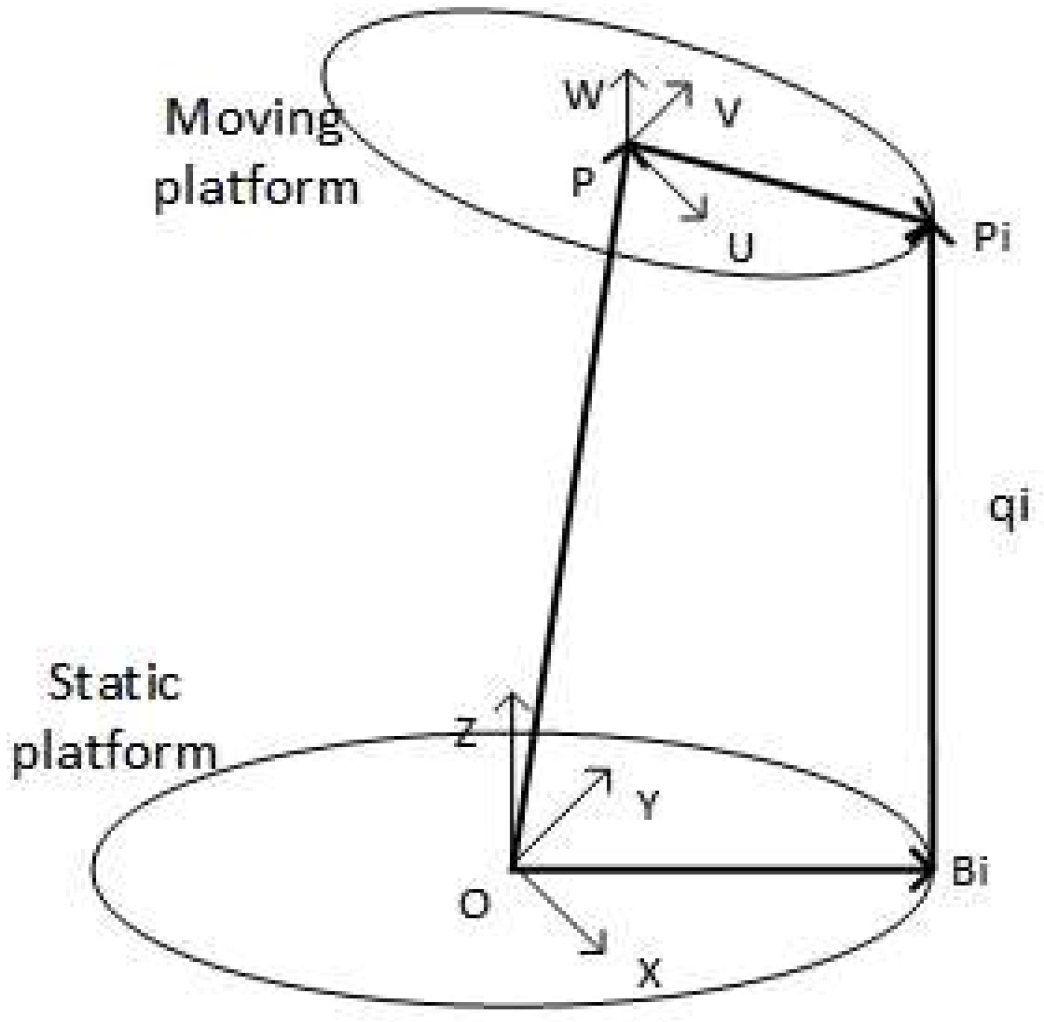
As shown in Figure 1, fracture reduction robots and deformity correction external fixators are all based on a parallel structure. These orthopedic robots can complete broken bone docking by position control accurately. Based on the parallel structure, orthopedic robots have big advantages for the bone docking task [1,2], but so far, there is a lack of sufficient trajectory, which is detrimental for patient treatment. Since the invention of medical robots, studies of orthopedic robots have been continuous. Various robot systems [3,4] have been designed by scholars to solve the above problems, which are beneficial to patients for precise and safe treatment. However, the lines and B-spline curves [5,6,7] are only used for the trajectory planning of parallel robots. Although literature about the trajectory planning of orthopedic robots is very few, trajectory is important for parallel orthopedic robots. For the sake of fracture reduction, it is a process of resetting broken bones to normal morphology. Moreover, for deformity correction, it dissects abnormal bones and regrows them back into their normal form gradually. In other words, both fracture reduction and deformity correction require broken bones to be reset to normal position and morphology. Thus, the preoperative movement planning of broken bones, as the basis of orthopedic robot control, is necessary and important for robot-assisted surgery and movement. Furthermore, the performance of robots is vital for patient safety [8] and the clinical effect after the surgery, which are influenced by path planning. In addition, damage to the human would be minimized due to the smoothness and continuity of the robot movement. Meanwhile, it is difficult for the robot to deal with emergencies, and misoperations could damage soft tissue, such as muscles, because of uncertainty in the clinical environment [9]. It is necessary to avoid collisions between the broken bone and other human tissues, as well as repairing broken bone rapidly and accurately. Therefore, it is of great significance that the appropriate path planning methods and safety strategies are studied and introduced.
Fortunately, some intelligent methods of path planning have aroused the enthusiasm of researchers [10]. To date, there are several methods, such as genetic algorithm (GA), artificial potential field (APF) and rapidly exploring random tree algorithm (RRT). However, GA imitates biological evolution and variation [11]. It is advantageous in search and collision avoidance, but very difficult for environmental modeling. In the meantime, due to the unknown population of algorithm initialization, it would require a lot of computation and is disadvantageous for safe operation. APF is designed by the gravitational field function and the repulsive force function, which have a positive effect on the overall planning [12]. Nevertheless, it would be harmful to avoid the collision force when the repulsion and gravitation forces are equal. Simultaneously, the quality of the path planning is dependent on the design of the potential field, which is difficult to derive. Additionally, the environment of the human body is very complicated, and orthopedic robots’ movements are related to human safety directly. So, the above-mentioned methods are unsuitable for the fracture reduction and deformity correction robot. RRT* has been proposed to obtain a shorter path than RRT [13], and it is effectively used for path planning in complex environments with a stronger ability for searching and has a better effect on collision avoidance. Tomasz, R. [14] realized the point-to-point trajectory planning of manipulators by RRT, and collision was avoided, which reflected the effectiveness of RRT in solving motion problems in three-dimensional space. Sakamoto, T. [15] also applied RRT* to path planning for palletizing or de-palletizing tasks, and the superiority of the algorithm was fully shown and demonstrated compared with conventional planning methods. Combining RRT* with D* lite, Chao, N. [16] presented the DL-RRT* algorithm for trajectory planning in radioactive environments, and the efficiency of path planning was improved. Kim, M.C. [17] proposed a wrapping-based informed RRT* by sampling the random path nodes within a hyper ellipsoid and tested it in various environments for superior verification. However, it seems that the results obtained by RRT* did not achieve the optimal path, and the problem of inefficiency in planning was not solved completely [18]. Moreover, since the real-time performance is impacted by the numbers of search nodes [19], it is crucial to obtain an optimal path for the robot movement [20] and improve the node utilization in practical application. In short, RRT* has been widely used for path planning in various robots, but it is not applied in surgical robots, in particular, orthopedic robots. Considering the lack of field studies and the complexity of the human body, it is necessary to apply cutting-edge methods to solve the problem.
In view of the above analysis, we introduced an improved RRT* method based on a computer for preoperative planning and path planning of an orthopedic robot (Figure 1). Meanwhile, we aimed to solve the algorithm of inefficiency and inadequate optimization in path planning, as well as the difficulty in smoothness. To this end, an improved RRT* was proposed based on target constraints and guidance strategy, and corresponding simulation analysis and platform tests were conducted. Finally, the feasibility and superiority of this method are confirmed, respectively.

2. Problem Description and Collision Detection

2.1. Problem Description

According to Arbeitsgemeinschaftfür Osteosynthesefragen (AO) classification [21], long bone fracture can be divided into type A, type B and type C, and each type consists of three injury degrees: level 1, level 2 and level 3, respectively. Type A is named sample malposition, such as oblique and transverse. Type B is composed of spiral bone fractures, while type C is complicated bone fractures such as comminuted bone fracture. Actually, AO classification has a certain guiding effect on the path planning of the robot. However, the standard of operation between the robot and the doctors is quite different. In most cases, type A and B could be treated easily by clinicians, but it is difficult for the robot to find the over-pull point and obtain the reset path because of the complicated human body. Indeed, the errors should be increased when the doctors splice the broken bones, while the robots could improve the accuracy and efficiency of operation for type C. Therefore, shortening and rotational malposition are selected for path planning in this paper.
In general, the bone fracture is divided into proximal fragment and distal fragment, where we regard the distal fragment as far away from patient’s head. The problem is normally described as follows: (1) the proximal and the distal fragment are fixed on the robot; (2) the robot is controlled along the path planning for position adjustment between the proximal and distal fragment; (3) the bone docking task is driven and completed by the robot. Specifically, the movement is regarded as point-to-point, and the collision is avoided under the robot constraints, such as maximum offsets. Therefore, firstly, the movement should be constantly close to the target to improve efficiency and reduce damage to the human body due to excessive offset of the path. Secondly, because the environment of the broken bone in the clinical is one of uncertainty and variability after the robot begins moving, a safety strategy is essential. Additionally, it is necessary to introduce a strategy for collision avoidance. Thirdly, the movement of the robot should be as smooth, continuous and short as possible to avoid injury to the human body.
Based on the above analysis, RRT* was imported for path planning and improved for algorithm performance. Aiming at the first and second points, target guiding strategy and constrained selection search point strategy were imported to improve the efficiency and the optimization problem. Moreover, the method of bounding box detection was introduced to ensure the safety in the movement of the robot. Aiming at the third key point, the problems of path smoothness and continuity were solved by spline curve. Usually, spline curve is used to bring a smoother path, so that the stability and continuity of the movement can be ensured. Then, inverse kinematics was used to reveal the movement on the drive actuators as the input to control the robot. Additionally, the position of the driving actuators was fitted by a seventh degree polynomial in order to realize the constraint and smoothness of the robot.

2.2. Collision Detection

In order to avoid any possible physical contact between the distal fragment and other parts during the robot movement, a collision detection method based on a bounding box was introduced. In general, cuboid and sphere bounding boxes are used to wrap the obstacles, and safety is confirmed when there is no intersection between the robot path and the bounding boxes. However, for distal fragment and proximal fragment, the possible solutions space is reduced only through the sphere or rectangle bounding boxes. In the meantime, the results, such as the reduction accuracy, are affected. Therefore, the bounding boxes should be as close to the shape of the bone and the obstruction as possible. According to anatomy, the bone is the human tissue with the shape of a cylinder, and the obstacles on the path are surrounded by spheres with a certain radius, so “cylinder + sphere” is adopted to represent the collision area. The collision-free conditions are described as follows.
{ ( x x f ) 2 + ( y y f ) 2 > r s a f e , z min < z < z max ( x x 0 ) 2 + ( y y 0 ) 2 + ( z z 0 ) 2 > a s a f e
where x, y and z represent the position on the path, and rsafe and asafe are the safe distance. xf and yf represent the center of the skeleton cross section. zmin and zmax represent the length of the cylinder. x0, y0 and z0 represent the sphere center.
The plane projection of the shortening and rotational malposition is displayed in Figure 2b. It could be observed that o1 is the start, and O2 is the goal. The process of the bone docking is to control o1 to move to O2, while the barriers on the path should be avoided. Figure 2a shows a critical condition diagram of the collision between the distal fragment and the proximal fragment. Meanwhile, the rectangle of the dotted line is the obstacle; thereby, O3 would not be admitted to be in this scope. Moreover, the radius of the cylinder is determined by the width of the rectangle. Therefore, the path is presented in the outside of the rectangle.

3. Improved RRT* Algorithm

RRT* with concise structure, real time and scalability is proposed to obtain a shorter path based on RRT. By adding the rewire operation, the path cost can be reduced. However, RRT* still has some randomness in the path planning, and the efficiency and security cannot be guaranteed. Moreover, RRT* cannot fully satisfy the requirement of the bone docking path. Therefore, further improvement was conducted as follows.

3.1. Sampling Strategy

The sampling in RRT* is random and blind and increases the path cost. As shown in Equation (2), pa is defined as the target bias probability [22]; p is the sampling probability with a random number and could be compared with the pa.
{ x g o a l , p < p a x r a n d , p > p a
In this paper, pa is set larger to make sure the sampling point is close to the target initially, so the sampling guidance to the target is promoted. Secondly, the sampling point set with randomness every time should be closer than the former set randomly to the target. Therefore, the search space of the path is continuously reduced, while the sampling point is farther away from the target in the axial distance than the last, and the re-sample would be set until the requirements are met.

3.2. Extension Strategy

Because of the blindness of sampling, the extension point would be also blind in the view of the global point. In order to overcome this shortcoming, an extension strategy is proposed based on the idea of artificial potential field. The extension point is determined by the sampling point and the target [23]. The tree can be extended by assigning different weight coefficients to them. Therefore, the extension point is closer to the target, and the expansion efficiency could be improved. Meanwhile, the path cost would be reduced indirectly. According to Equation (3), the expansion node xnew can be obtained, and the expansion formula is as follows:
x n e w = x n e a r e s t + σ ( ξ n g o a l + ( 1 ξ ) n r a n d )
n g o a l = x g o a l x n e a r e s t x g o a l x n e a r e s t
n r a n d = x r a n d x n e a r e s t x r a n d x n e a r e s t
where σ is the size of the step, ξ is the weight coefficient, xrand is the random node of the tree according to Equation (2), and xnearest is the closest node to the xrand. Meanwhile, xgoal is the target.
Due to the randomness of the RRT*, the maximum number of attempts for path searching every time is set as attemptmax, and the variable weight is introduced for point extension by changing the guidance degree. When the searching space is sufficient and the target is surrounded without obstacles, the extension point is guided for the target. Otherwise, the point would stop expanding, and the randomness of the local space for searching would be lost. Therefore, the strategy is directed by the target at the beginning of the iteration with a high inertia weight, while it is transited to the lower value to carry out local search for random search so as to promote the searching efficiency of the algorithm. The weighting function of ξ is:
ξ = ξ attemptmax K attemptmax
where attemptmax is the maximal iterations, and K is the current iterations.
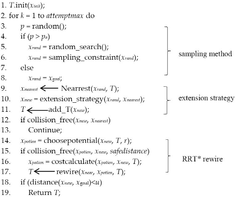
At the end, the algorithmic program of the improved RRT* was shown in Algorithm 1, which includes the sampling constraint, node extension, tree update and the path connect. In Algorithm 1, xpotien is the potential node closest to the xrand in rewire strategy.
Algorithm 1 Algorithmic program of the improved RRT*.
Build_improverd_RRT*(xinit, xgoal, attemptmax)
Machines 10 00480 i001

3.3. B-Spline Fitting

The path obtained by the improved RRT* is connected with extension points, which are based on a straight line. As a result, lots of angles appear between the extension points. So, the robot speed and acceleration are changed suddenly when the angle is presenting, which could cause some damage to the robot movements. B-spline curve [
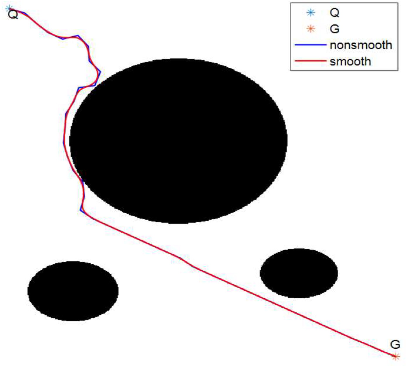
24] is widely used in path smoothing. Meanwhile, it is advantageous in approximating polygons with higher precision and maintains the path shape despite the modified local. Therefore, combining the problem description above, a B-spline curve is used in this paper. Moreover, a two-dimensional map was introduced and established using MATLAB. In the meantime, the path between the start and the goal was obtained by the improved RRT*, and the path fitting function was written using a B-spline curve. The comparison with smooth and without smooth was shown in Figure 3, in which Q is the start point, and G is the goal point. Additionally, the red line was the path after smoothing. It can be found that the path shape in global was as before without change, and the angles were removed even if the original path was smoothed.

4. Kinematics Analysis and Polynomial Fitting

4.1. Kinematics Analysis

Based on our orthopedic robot in Figure 1a, the robot kinematics analysis reveals a corresponding relationship between the moving platform and the drive actuators. The model of the parallel structure is shown in Figure 4. The model and the inverse kinematics have been established, and the inverse formula has been derived [25]. In this paper, the forward kinematics is solved by the iteration method [26,27] for the moving platform path verification, and Pi and Bi (i = 1, 2, 3, …, 6) represent the hook hinge center; qi (i = 1, 2, 3, …, 6) represents the vector of drive actuator.
The forward kinematics is solved as follows. Given the parameters of the mechanism and the length of each branch chain qim (i = 1, 2, 3, …, 6), l, which is the position and attitude of the moving platform, is solved, which is represented as [x, y, z, ϕ, φ, σ]. Substituting the six branch chains’ length into the equations of inverse kinematics, the equations containing six unknown parameters can be obtained. Then, the method of searching the optimal value according to the iterative method can be used to obtain results. We can obtain the following.
F ( l ) = [ f 1 f 2 f 3 f 4 f 5 f 6 ] = [ q 1 m ( O P + R · P P 1 O B 1 ) T ( O P + R · P P 1 O B 1 ) q 2 m ( O P + R · P P 2 O B 2 ) T ( O P + R · P P 2 O B 2 ) q 3 m ( O P + R · P P 3 O B 3 ) T ( O P + R · P P 3 O B 3 ) q 4 m ( O P + R · P P 4 O B 4 ) T ( O P + R · P P 4 O B 4 ) q 5 m ( O P + R · P P 5 O B 5 ) T ( O P + R · P P 5 O B 5 ) q 6 m ( O P + R · P P 6 O B 6 ) T ( O P + R · P P 6 O B 6 ) ] = [ 0 0 0 0 0 0 ]
Next, we can obtain a formula based on the Taylor formula and recursion,
l n + 1 l n + J 1 ( l n ) ( q m q n )
where J is
[ n 1 T ( P 1 × n 1 ) T n 2 T ( P 2 × n 2 ) T n 3 T ( P 3 × n 3 ) T n 4 T ( P 4 × n 4 ) T n 5 T ( P 5 × n 5 ) T n 6 T ( P 6 × n 6 ) T ] [ 1 0 0 0 0 0 0 1 0 0 0 0 0 0 1 0 0 0 0 0 0 cos ( σ ) cos ( ϕ ) sin ( σ ) 0 0 0 0 sin ( σ ) cos ( ϕ ) cos ( σ ) 0 0 0 0 sin ( ϕ ) 0 1 ]
and ni (i = 1, 2, 3, …, 6) is the unit vector of the branch chain qi. The value of l is the result of the pose. The steps are as follows.
(1)
Initialize the pose value l0;
(2)
Calculate the matrix J of the current pose value and the length of the branch chain by l0;
(3)
Judge whether the terminal condition is met. If so, the output has been obtained. Otherwise, the value should be updated according to Equation (7), and the current step should be repeated until the terminate condition is met.

4.2. Polynomial Fitting

In the same way, based on the orthopedic robot, the moving platform path is obtained by RRT* and discretized secondly. Then, inverse kinematics is used to get the actuators length for drive. However, the path and the actuator length are discrete. The speed and acceleration of the robot could be affected with mutation. So, there is a significant possibility of causing injury to the human body by sudden arrest when the robot completes the bone docking task. In this paper, a higher-degree polynomial is used to match the length of the drive actuator, and continuous variation within a range of values would be actualized. Generally, a quintic polynomial [28] could be used to realize acceleration planning. Therefore, considering the continuous movement, speed and acceleration of the moving platform, a seventh degree polynomial was selected for the drive actuators length fitting. The equation is as follows.
f ( t ) = a 0 + a 1 t + a 2 t 2 + a 3 t 3 + a 4 t 4 + a 5 t 5 + a 6 t 6 + a 7 t 7
So, the equation for the speed and acceleration could be obtained by the first and second derivatives of Equation (9).
f ( t ) · = a 1 + 2 a 2 t + 3 a 3 t 2 + 4 a 4 t 3 + 5 a 5 t 4 + 6 a 6 t 5 + 7 a 7 t 6
f ( t ) · · = 2 a 2 + 6 a 3 t + 12 a 4 t 2 + 20 a 5 t 3 + 30 a 6 t 4 + 42 a 7 t 5
Meanwhile, in order to ensure smaller jerk and stationarity of the robot movement, the boundary conditions for the speed and acceleration are defined as follows:
{ f ( 0 ) = l 0 f ( t f ) = l f f ( 0 ) · = 0 f ( t f ) · = 0 f ( 0 ) · · = 0 f ( t f ) · · = 0 | f ( t ) · | v max | f ( t ) · · | a max
In addition, the accuracy must be guaranteed for polynomial fitting, especially on the initial length and the final length of the drive actuators. Therefore, the fitting problem is expressed of an unconstrained optimization problem; thereby, a minimization optimization model is established with the objective function obtained by the errors. The objective function is as follows:
min g ( x ) = i = 1 n [ f i ( t ) f i d ] 2
where n is the number of fitting points, fid is the expected length, and fi(t) is actual length. The fmincon of MATLAB is used for problem optimization. In the first place, the unknown coefficients are initialized, and the boundary contains are set. Then, the fmincon function is solved for optimization.

5. Verification Experiment

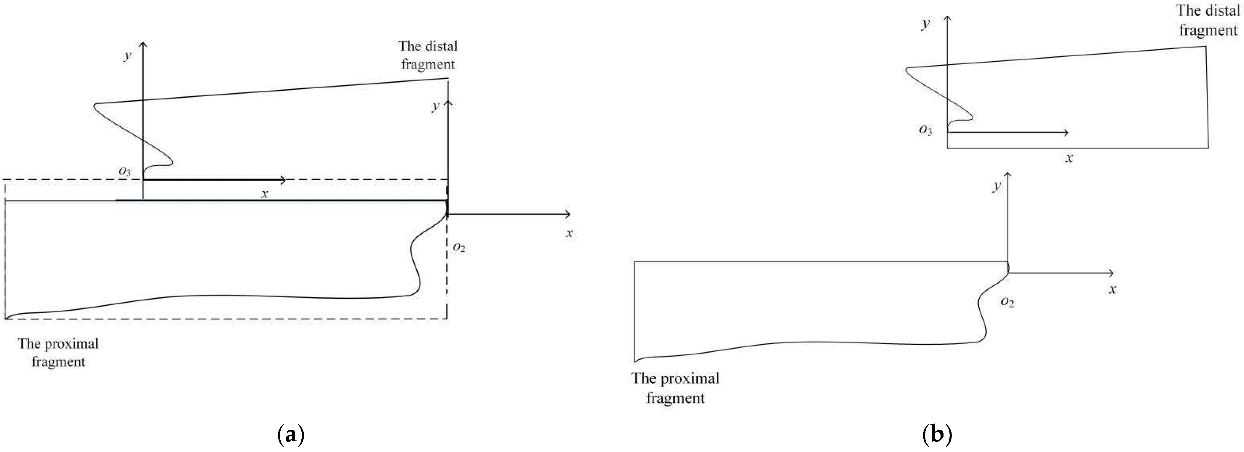
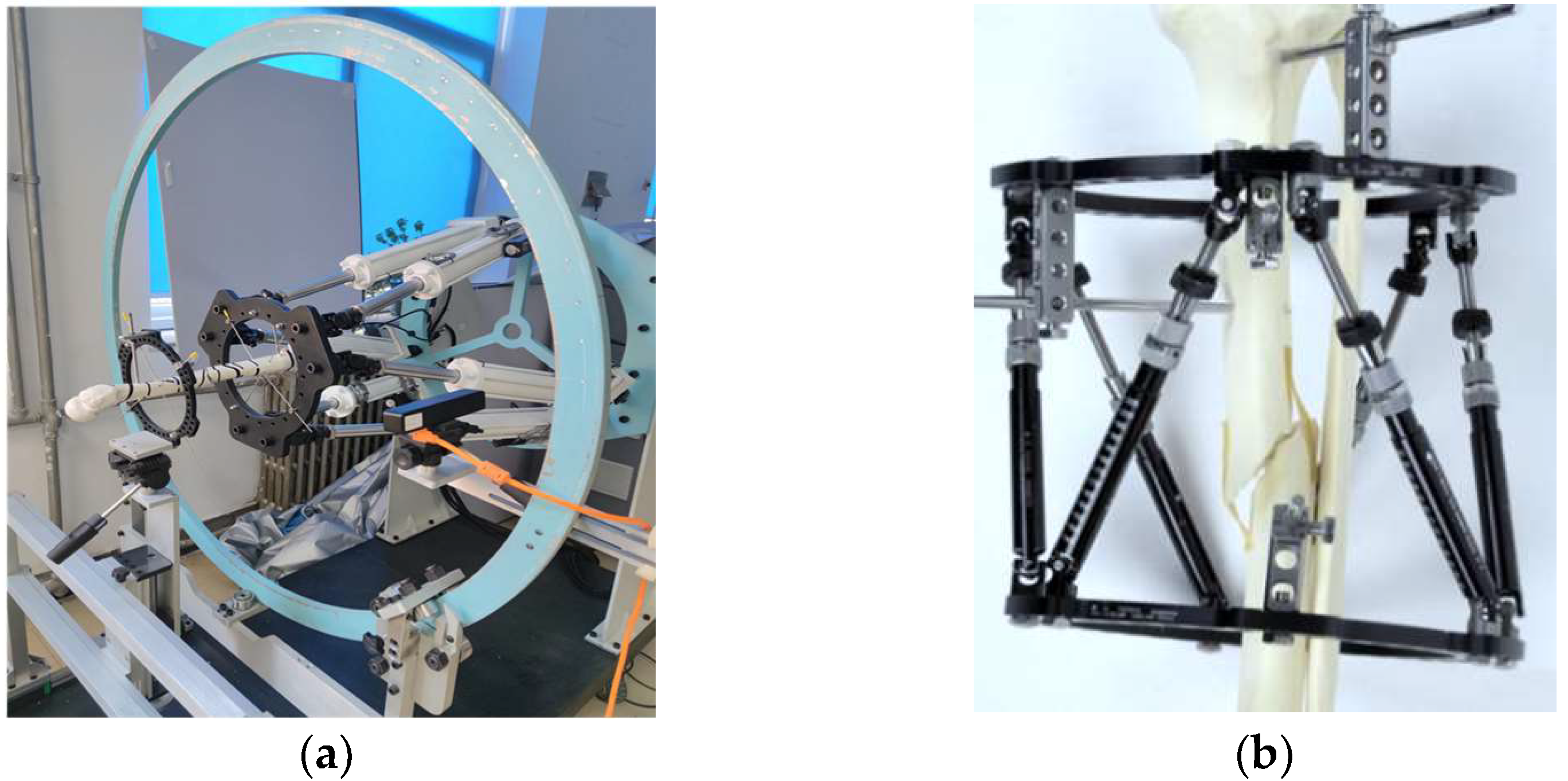
The fracture reduction robot in Figure 1a was designed by us, including the hardware and software. The hardware contains a monitor, a modbox controller, a motor and six drive rods, which are the actuators. Correspondingly, the software is applied on a computer, which includes the interface designed by MATLAB and Abaqus for force-displacement analysis.
Taking the fracture reduction robot designed by us in Figure 1a as the object, the parameters of the parallel robots were set: the minimum length and the maximum length of the drive rods were 569 mm and 800 mm, respectively, and the maximum angle of the cross universal hinge was 70°. The path was planned in the workspace. The simulation was realized by MATLAB 2016a, which was installed on a Thinkpad computer.
In order to verify the feasibility and the superiority of the improved RRT* algorithm, further experiments were developed by the algorithm simulation and platform simulation, and shortening and rotational malposition are selected for path planning. First of all, for the algorithm simulation, one case is adopted where shortening and rotational dislocation occurred. The distal fragment is regarded as the start, and the proximal fragment is regarded as the goal, where the coordinates were [10, 10, 560] and [0, 0, 600], respectively. Meanwhile, Euler angles whose relative positions were between the proximal and distal fractures were 12°, 15° and 10°, respectively. The experiment was carried out by algorithm simulation, in which the improved RRT* algorithm was compared with RRT*. Secondly, based on our orthopedic robot (Figure 1a), the improved RRT* algorithm was applied for planning, and platform simulation was conducted. Moreover, in order to ensure the start and stop of the robot motion and the features of more intuitive control, the trajectory planning in the joint space is carried out by means of seventh degree polynomial. In the meantime, forward kinematics analysis of the parallel robot was executed in order to verify the effectiveness of the polynomial fitting method.

5.1. Algorithm Simulation

The RRT* algorithm and the improved RRT* algorithm were used for path planning, while the start and the goal for the algorithms were the same. Because of the randomness of the RRT* and the improved RRT*, the repeated experiments, which contained 100 repetitions, were counted to exhibit the universality and superiority of the improved algorithm. Additionally, sampling-based planning algorithms, such as PRM, LazyPRM, RRT-connect and LazyRRT, were selected for the comparisons, as well as for application for the repeated experiment above. Meanwhile, the average length and the average nodes were obtained and are shown in Table 1 and Table 2. However, the RRT* and the improved RRT* was the main comparison in 
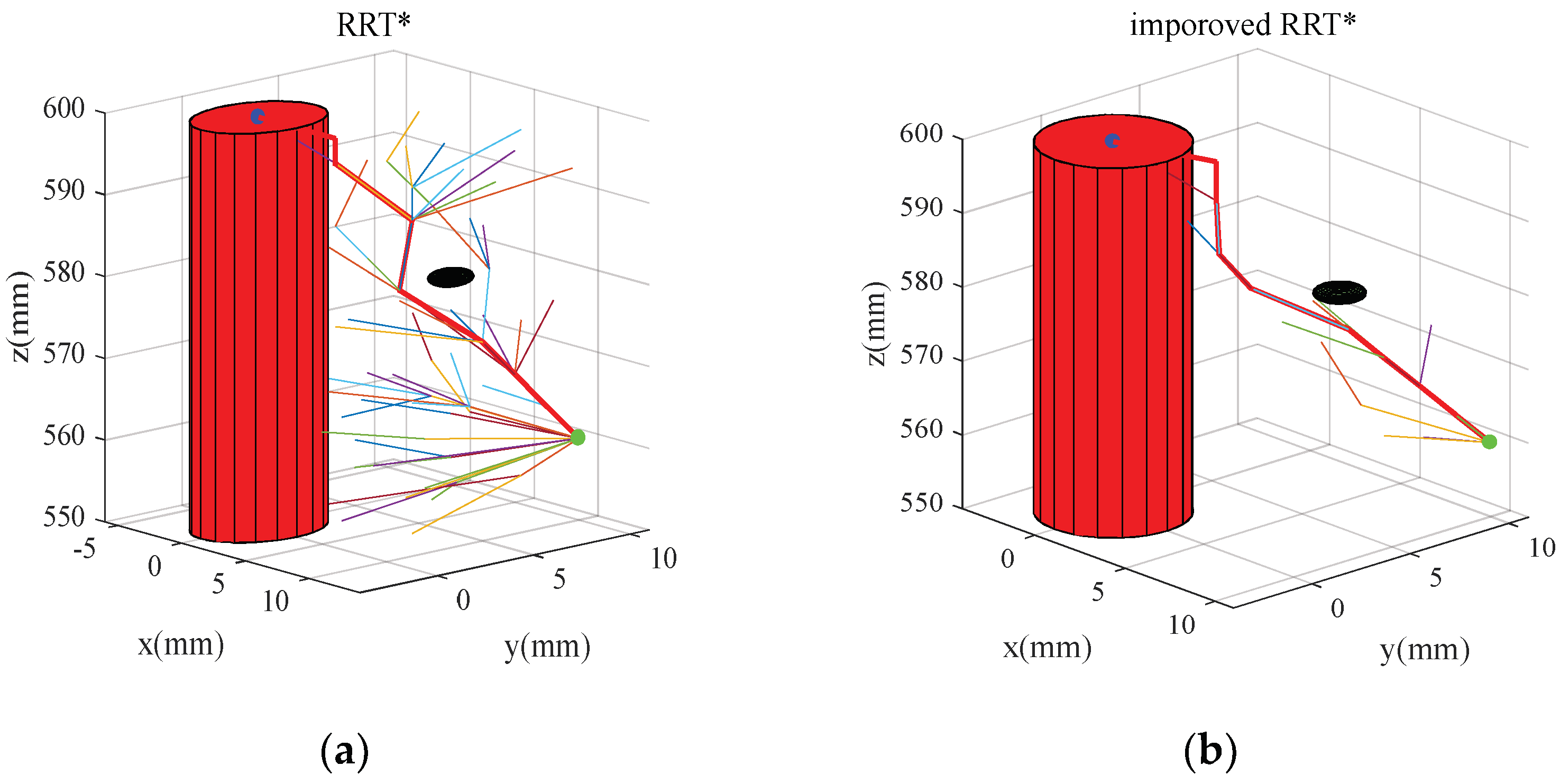
algorithm simulation. The results for path planning are shown in Figure 5. The cylinder represented the boundary conditions, and the black sphere represented the obstacles on the path. In the meantime, the bold red line represented the path by the algorithm, and the dots represents the start and the goal. It can be seen from Figure 5 that the RRT* algorithm was suitable for the path planning of the dynamic and complicated environment, but lots of broken lines were present on the path, and the target directivity was not ideal. Furthermore, the path length and the node utilization were compared in Table 1 and Table 2, in which the latter represented the proportion of the workable nodes to the total nodes. In Table 1, the path length was selected to reveal the algorithm advantage, which is an important parameter of orthopedic robots. It was observed that the average path planned by the RRT* costed 46.5109 mm, while the result by the improved RRT* was 45.4918. Obviously, in order to improve the efficiency of corrective surgery, the latter was shorter and could be more suitable for orthopedic robots. As shown in Table 2, The average workable nodes of RRT* accounted for 9.15, and the average total nodes were 549.26, so the average node utilization was about 1.66%. Similarly, the average workable nodes number of the improved RRT* accounted for 9.24, and the average total nodes number is 371.82, so the node utilization was about 2.49%. It was clearly that the node utilization of improved RRT* was greater than that of the RRT*.
Relatively, the improved RRT* had the most optimal path, which is the shortest in the six algorithms. However, it is not shown the greatest node utilization, where PRM, RRT-connect and LazyPRM are all superior to the improved RRT*. Generally, how to complete the reduction and operation with the shortest path is very important in the malformation correction surgery. Although improved RRT* still has shortcomings in node utilization, its characteristic of shortest path is worthy of affirmation. Additionally, the mechanism of each algorithm is different and have their advantages and disadvantages. In other words, comparative studies are only meaningful if the mechanism is the same or similar. In terms of node utilization, the improved RRT* is superior to RRT* and LazyRRT, in which the improved RRT* has the same or similar mechanism to the RRT*. Therefore, this kind of comparison is persuasive.
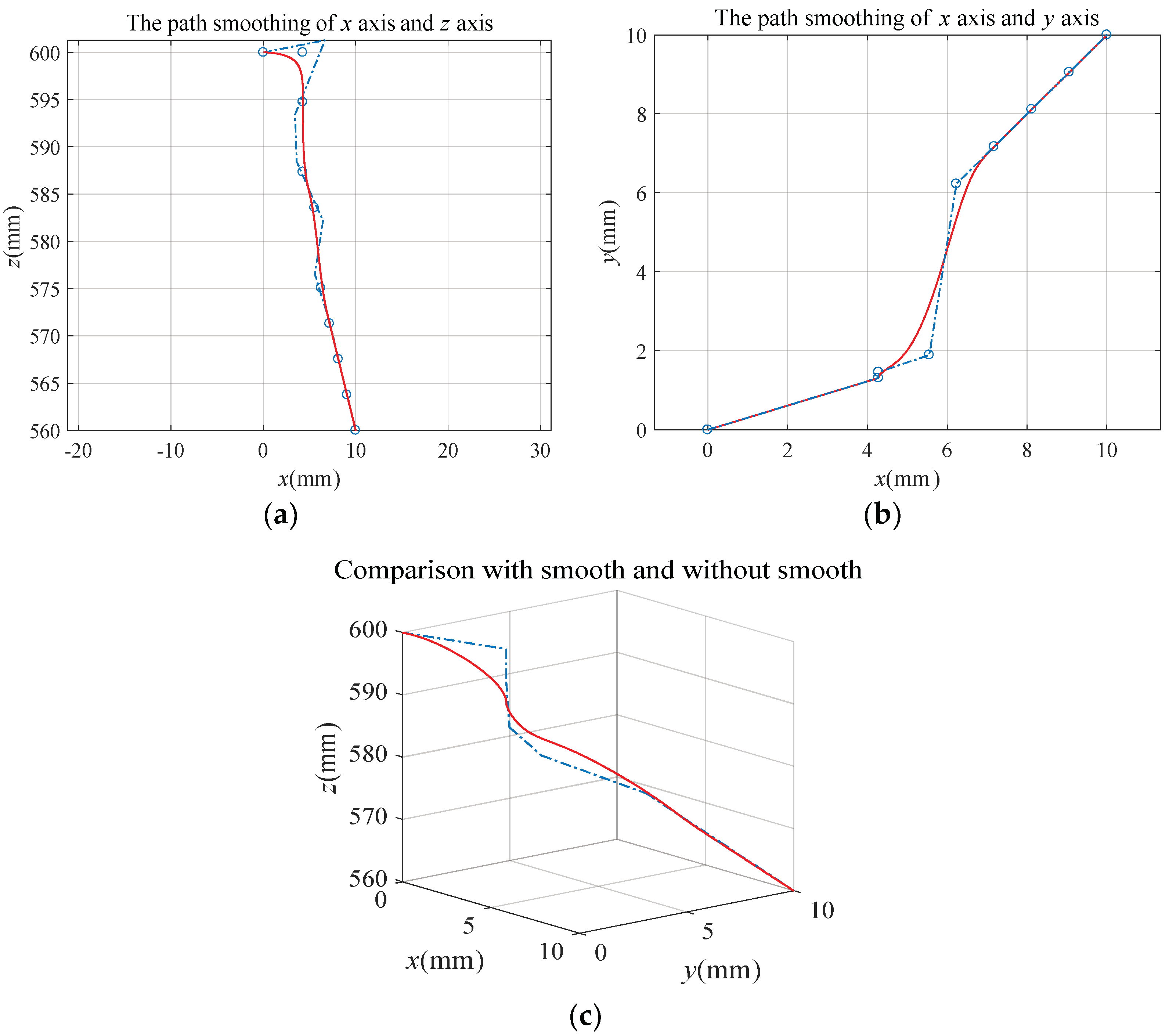
Meanwhile, with the improved RRT*, the B-spline curve was used for path smoothing. As exhibited in Figure 6, the path was obtained by the improved RRT* and smoothed by the three B-spline curve. In Figure 6a,b, paths from different angles are shown, and the circles represented the control points on the path, which could be connected with lines and create the path. Moreover, the red lines represented the results of the smoothed path. Meanwhile, a comparative study with smooth and without smooth is displayed in Figure 6c. All of the above results confirmed that the improved RRT* could be used for path planning, and B-spline curve could provide safety assurance because of its good continuity and smoothness. Moreover, the problem of large angle bending in the process of reset and correction is solved with the smoothing B-spline curve, which could avoid the damages to the human environment caused by the excessive angles. Furthermore, the above results indicate that, combined with the improved RRT* path planning method and B-spline curve smoothing method, orthopedic robots could realize the alignment of broken bones and improve the safety of path planning. Thus, it would provide a reference for doctors’ preoperative planning and serve as the basis for robot movement.

5.2. Platform Simulation

Trajectory planning is the basis of robot motion control, which guides the robot to complete the treatment task. In parallel with the algorithm simulation, platform simulation based on our orthopedic robot platform (
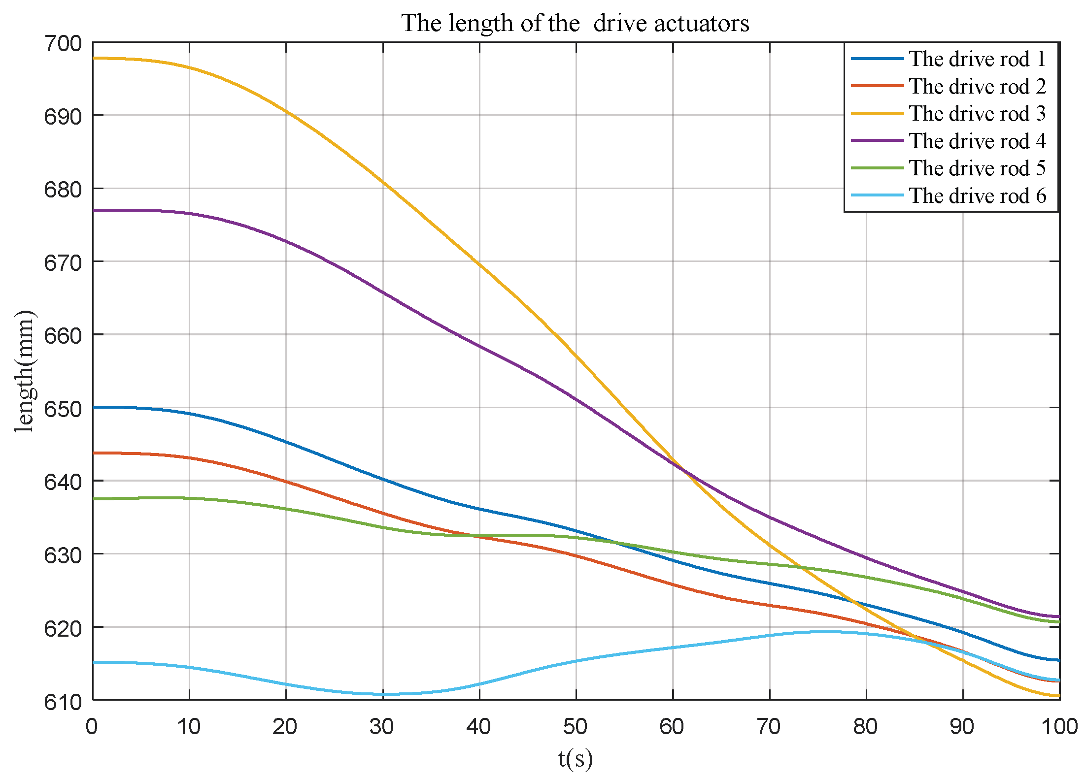
Figure 1a) was completed, and drive actuator lengths by inverse kinematics are shown in 
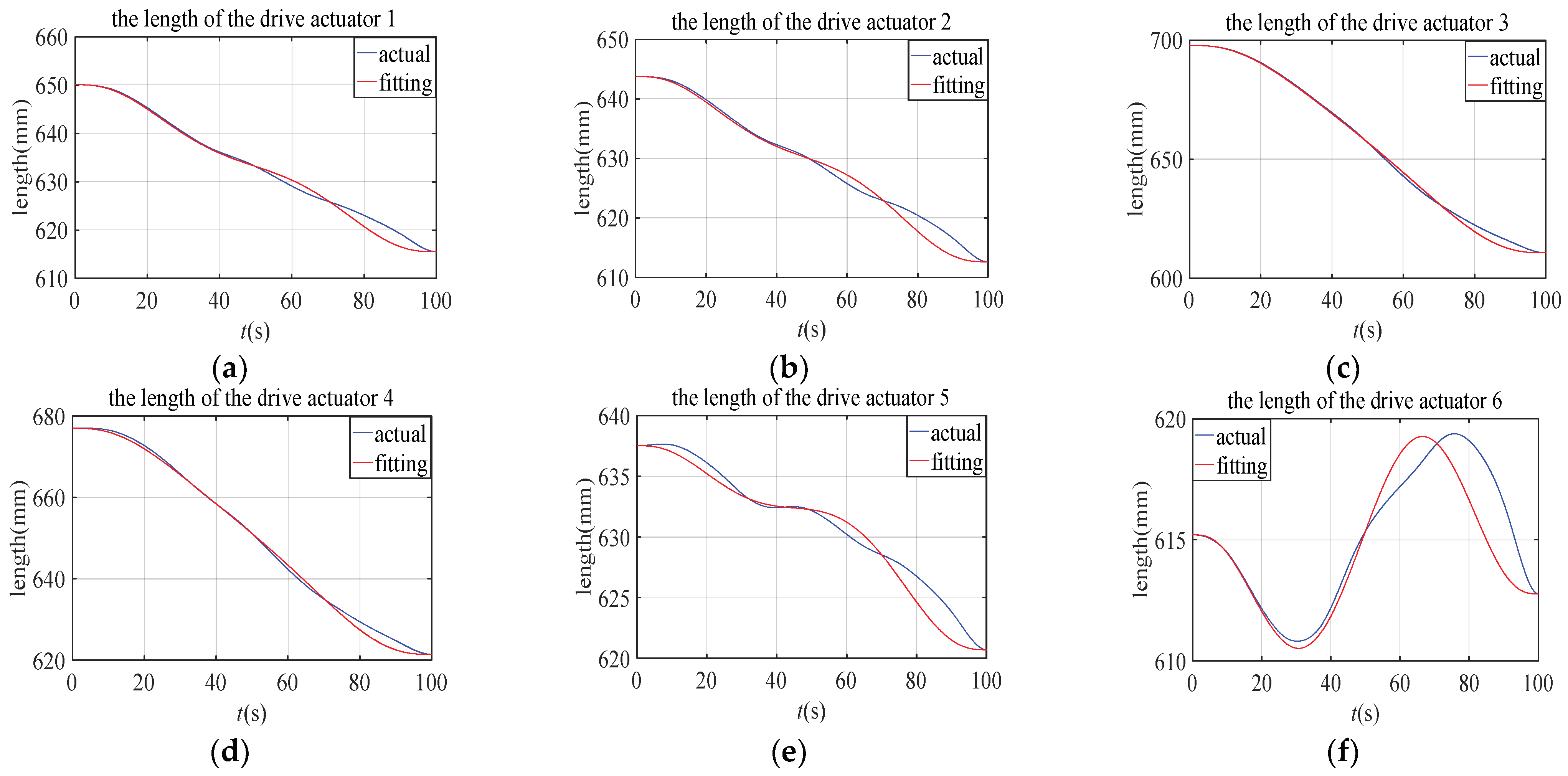
Figure 7. All the lengths were changed from 610 to 700. Additionally, for the drive actuators’ length fitting, the plots of the six drive actuator lengths are displayed and compared in Figure 8. It was found that the polynomial fitting method could realize trajectory planning in joint space well. Moreover, combined with the improved RRT* and B-spline curve, the motion control of the orthopedic robot could be realized more intuitively, and the speed and acceleration could be guaranteed from 0 to 0 at the initial moment. This solves the problem of speed and acceleration mutation of the drive rods, thus improving the safety of the robot.
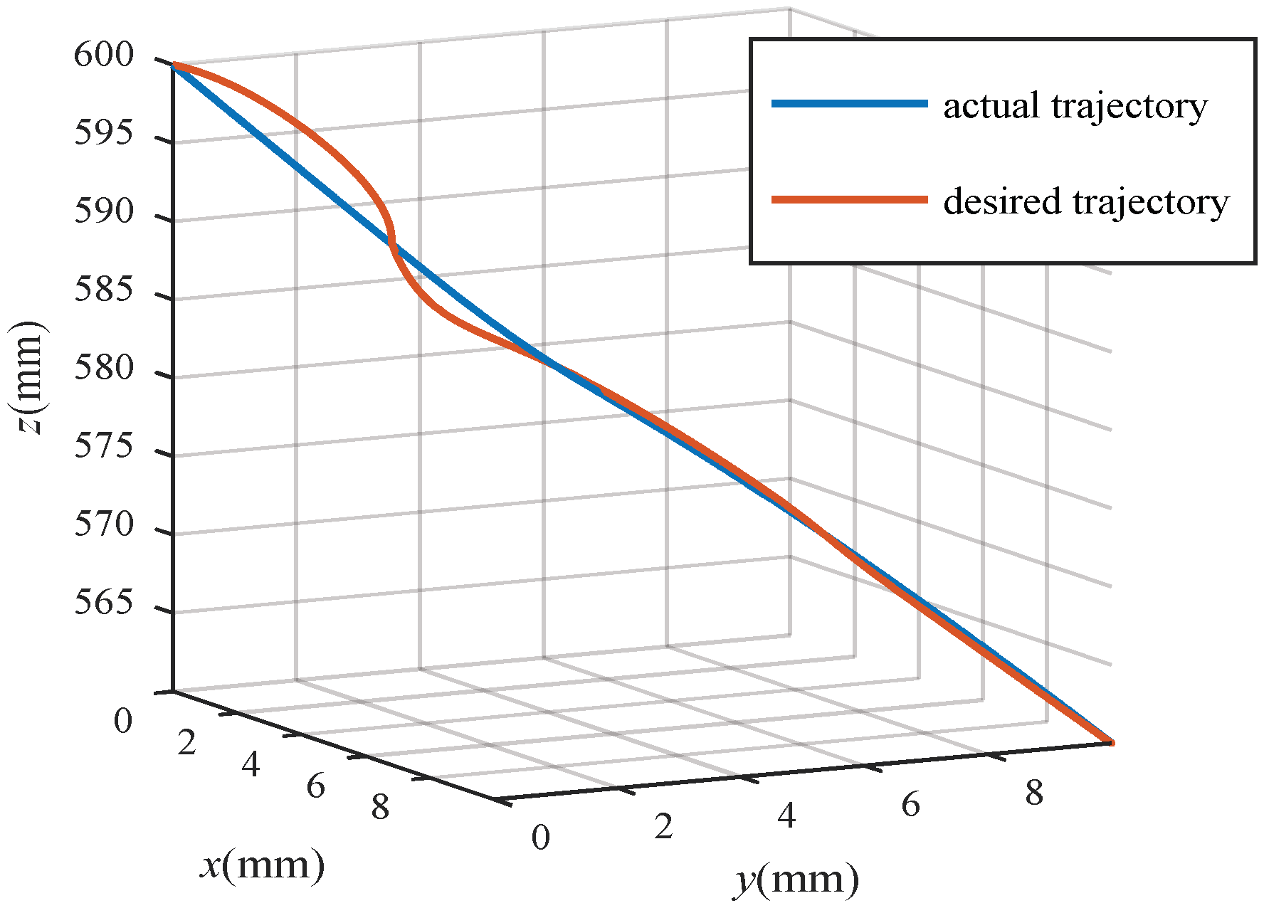
Meanwhile, in Figure 9, a simulation comparison is displayed between the desired trajectory and the actual trajectory. The red line is the desired trajectory planned by the improved RRT* algorithm with B-spline curve smoothing, and the blue line is the actual trajectory of broken bone movement obtained by monitoring the forward kinematics analysis of the platform under polynomial fitting results. The results show that both of them could achieve a reduction in broken bone, and the latter could control the speed and acceleration of the robot drive rod. Therefore, the polynomial fitting could combine trajectory planning with the robot platform to complete the bone-breaking docking task while greatly improving the safety of the robot. Additionally, the effectiveness and feasibility of the method were verified.

6. Conclusions

The line [29] and the spline curve [30] have been used for path planning, but they only expect that the injury to the human body is as small as possible. The strategies for path planning are unsatisfied, and the path is not optimal. In this paper, the improved RRT* has been selected for the path planning of the parallel orthopedic robot. The results reveal that the length and the node utilization of improved RRT* are greater than RRT*. Then, a B-spline curve is used for path smoothing to avoid sudden changes in the path. Compared with RRT*, shorter path and high node utilization were shown in the improved RRT*, which cut down about 1mm in the average path length and increased about half in the average node utilization. It could be concluded that the improved RRT* is superior, and the path planning method proposed by us could be realized simply for parallel robot trajectory planning.
Although some significant results were obtained, there are also some limits in this study. Firstly, the muscles toughed on the broken bone were ignored. However, in the movement of the robot, the influence of the muscle is very important. The dynamic model of the robot and muscle–bone should be considered in the path planning for constraints in the future. Secondly, the interference of a muscle’s morphology was not considered. Nevertheless, shape changes of the muscle will influence the bone docking in the clinical process. Thirdly, in terms of node utilization, the improved RRT* is still inadequate. In the future, a complex model that includes morphology changes should be considered for path planning, and further research on improvements inspired by the merits of PRM, RRT-connect and LazyPRM is needed.

Author Contributions

Conceptualization, J.L.; methodology, R.C.; software, R.C.; validation, J.L., R.C. and H.S.; formal analysis, R.C. and P.S.; investigation, P.S. and L.M.; resources, J.L.; data curation, P.S.; writing—original draft preparation, J.L. and R.C.; writing—review and editing, J.L. and R.C.; visualization, L.M.; supervision, H.S.; project administration, J.L.; funding acquisition, J.L. All authors have read and agreed to the published version of the manuscript.

Funding

This research was funded by National Natural Science Foundation of China grant numbers 52005120 and 52005045, Beijing Municipal Natural Science Foundation grant number 19L2018, Beijing Outstanding Young Backbone Personnel Training Project grant number 2017000026825G280 and Fundamental Research Funds for Central Public Welfare Research Institutes grant number 118009001000160001. The APC was funded by Beijing Outstanding Young Backbone Personnel Training Project.

Data Availability Statement

All data generated or analyzed during the study are included in the article, and the data that support the findings of this study are openly available.

Acknowledgments

Thanks for the supports by National Natural Science Foundation of China (Nos.52005120 and 52005045), Beijing Municipal Natural Science Foundation (No.19L2018), Beijing Outstanding Young Backbone Personnel Training Project (No.2017000026825G280) and Fundamental Research Funds for Central Public Welfare Research Institutes (No. 118009001000160001).

Conflicts of Interest

The authors declare no conflict of interest.

References

  1. Füchtmeier, B.; Egersdoerfer, S.; Mai, R.; Hente, R.; Dragoi, D.; Monkman, G.; Nerlich, M. Reduction of femoral shaft fractures in vitro by a new developed reduction robot system ‘RepoRobo’. Injury 2004, 35, 113–119. [Google Scholar] [CrossRef] [PubMed]
  2. Li, J.; Li, G.; Dong, M.; Chen, Y.; Zuo, S. Comparison of three different correction trajectories for foot and ankle deformity treated by supramalleolar osteotomy using a novel external fixator. Int. J. Numer. Methods Biomed. Eng. 2020, 36, e3400. [Google Scholar] [CrossRef] [PubMed]
  3. Maeda, Y.; Sugano, N.; Saito, M.; Yonenobu, K.; Sakuma, I.; Nakajima, Y.; Warisawa, S.I.; Mitsuishi, M. Robot-assisted femoral fracture reduction: Preliminary study in patients and healthy volunteers. Comput. Aided Surg. 2008, 13, 148–156. [Google Scholar] [CrossRef] [PubMed]
  4. Dagnino, G.; Georgilas, I.; Köhler, P.; Morad, S.; Atkins, R.; Dogramadzi, S. Navigation system for robot-assisted intra-articular lower-limb fracture surgery. Int. J. Comput. Assist. Radiol. Surg. 2016, 11, 1831–1843. [Google Scholar] [CrossRef] [PubMed]
  5. Zhang, X.; Sun, H.; Chen, J.; Guo, Y.; Zhang, Y.; Sun, Z.; Wang, T.; Wei, M.; Zhang, Y.; Chen, L. Optimization of electronic prescription for parallel external fixator based on genetic algorithm. Int. J. Comput. Assist. Radiol. Surg. 2019, 14, 861–871. [Google Scholar] [CrossRef] [PubMed]
  6. Ye, R.H.; Wang, S.; Chen, Y.H. Tele-operation and simulation for a new surgical robot design. Comput. Aided Des. Appl. 2013, 8, 325–334. [Google Scholar] [CrossRef] [Green Version]
  7. Mahmood, R.A.; Rahmatolah, K. An algorithm for smooth trajectory planning optimization of isotropic translational parallel manipulators. Proc. Inst. Mech. Eng. Part C J. Mech. Eng. Sci. 2016, 230, 1987–2002. [Google Scholar]
  8. Joung, S.; Liao, H.; Kobayashi, E.; Mitsuishi, M.; Nakajima, Y.; Sugano, N.; Bessho, M.; Ohashi, S.; Matsumoto, T.; Ohnishi, I.; et al. Hazard Analysis of Fracture-Reduction Robot and Its Application to Safety Design of fracture-Reduction Assisting Robotic System. In Proceedings of the IEEE International Conference on Robotics and Automation, Anchorage, AK, USA, 3–7 May 2010; pp. 1554–1561. [Google Scholar]
  9. Li, C.; Wang, T.; Hu, L.; Zhang, L.; Zhao, Y.; Du, H.; Wang, L.; Tang, P. Robot-musculoskeletal dynamic biomechanical model in robot-assisted diaphyseal fracture reduction. Bio-Med. Mater. Eng. 2015, 26 (Suppl. S1), S365–S374. [Google Scholar] [CrossRef] [Green Version]
  10. Tsardoulias, E.G.; Iliakopoulou, A.; Kargakos, A.; Petrou, L. A review of global path planning methods for occupancy grid maps regardless of obstacle density. J. Intell. Robot. Syst. 2016, 84, 829–858. [Google Scholar] [CrossRef]
  11. Chen, X.M.; Liu, L.; Du, J.T.; Liu, D.; Huang, L.; Li, X. Intelligent optimization based on a virtual marine diesel engine using GA-ICSO hybrid algorithm. Machines 2022, 10, 227. [Google Scholar] [CrossRef]
  12. Zhao, T.; Li, H.D.; Dian, S.Y. Multi-robot path planning based on improved artificial potential field and fuzzy inference system. J. Intell. Fuzzy Syst. Appl. Eng. Technol. 2020, 39 Pt 2, 7621–7637. [Google Scholar]
  13. Kazraman, S. Sampling-based algorithms for optimal motion planning. Int. J. Robot. Res. 2011, 30, 846–894. [Google Scholar] [CrossRef]
  14. Tomasz, R. Point-to-point motion planning of a free-floating space manipulator using the rapidly-exploring random trees (RRT) method. Robotica 2020, 38, 957–982. [Google Scholar]
  15. Sakamoto, T.; Harada, K.; Wan, W.W. Real-time planning robotic palletizing tasks using reusable roadmaps. J. Robot. Netw. Artif. Life 2020, 6, 240–245. [Google Scholar] [CrossRef] [Green Version]
  16. Chao, N.; Liu, Y.K.; Xia, H.; Peng, M.J.; Ayodeji, A. DL-RRT* algorithm for least dose path re-planning in dynamic radioactive environments. Nucl. Eng. Technol. 2019, 51, 825–836. [Google Scholar] [CrossRef]
  17. Kim, M.C.; Song, J.K. Informed RRT* with improved converging rate by adopting wrapping procedure. Intell. Serv. Robot. 2018, 11, 53–60. [Google Scholar] [CrossRef]
  18. Noreen, I.; Khan, A.; Habib, Z. Optimal path planning using RRT* based approaches: A survey and future directions. Int. J. Adv. Comput. Sci. Appl. 2016, 7, 97–107. [Google Scholar] [CrossRef] [Green Version]
  19. Adiyatov, O.; Varol, H.A. Rapidly-Exploring Random Tree Based Memory Efficient Motion Planning. In Proceedings of the 2013 IEEE International Conference on Mechatronics and Automation, Kagawa, Japan, 4–7 August 2013; pp. 354–359. [Google Scholar]
  20. Yang, Y.J.; Jia, P.; Wan, W.W. Survey of optimal motion planning. IET Cyber-Syst. Robot. 2020, 1, 13–19. [Google Scholar] [CrossRef]
  21. Masionis, P.; Uvarovas, V.; Mazarevičius, G.; Popov, K.; Venckus, Š.; Baužys, K.; Porvaneckas, N. The reliability of a Garden, AO and simple II stage classifications for intracapsular hip fractures. Orthop. Traumatol. Surg. Res. OTSR 2019, 105, 29–33. [Google Scholar] [CrossRef]
  22. Urmson, C.; Simmons, R. Approaches for Heuristically Biasing RRT Growth. In Proceedings of the 2003 IEEE/RSJ International Conference on Intelligent Robots & Systems, Las Vegas, NV, USA, 27–31 October 2003; pp. 1178–1183. [Google Scholar]
  23. Zhang, W.M.; Fu, S.X. Mobile robot path planning based on improved RRT* algorithm. J. Huazhong Univ. Sci. Technol. (Nat. Sci. Ed.) 2021, 49, 31–36. [Google Scholar]
  24. Chen, Y.D.; Li, L. Collision-free trajectory planning for dual-robot systems using B-splines. Int. J. Adv. Robot. Syst. 2017, 14, 641–644. [Google Scholar] [CrossRef]
  25. Fu, Z.; Sun, H.; Dong, X.; Chen, J.; Rong, H.; Guo, Y.; Lin, S. Indirect visual guided fracture reduction robot based on external markers. Int. J. Med. Robot. Comput. Assist. Surg. 2020, 17, 1–11. [Google Scholar] [CrossRef] [PubMed]
  26. Zhou, W.Y.; Chen, W.Y.; Liu, H.D.; Li, X.Y. A new forward kinematic algorithm for a general Stewart platform. Mech. Mach. Theory 2015, 87, 177–190. [Google Scholar] [CrossRef]
  27. Wang, Y.; Yu, J.J.; Pei, X. Fast forward kinematics algorithm for real-time and high-precision control of the 3-RPS parallel mechanism. J. Land Use Sci. 2018, 13, 368–375. [Google Scholar] [CrossRef]
  28. Xu, P.Y.; Hong, Y. Time optimal path planning of palletizing robot. Appl. Mech. Mater. 2014, 2890, 658–662. [Google Scholar] [CrossRef]
  29. Kim, W.Y.; Ko, S.Y. Hands-on robot-assisted fracture reduction system guided by a linear guidance constraints controller using a pre-operatively planned goal pose. Int. J. Med. Robot. + Comput. Assist. Surg. MRCAS 2019, 15, e1967. [Google Scholar] [CrossRef]
  30. Deokkyun, Y.; Chinedum, E.O. Active assist device for simultaneous reduction of heat and vibration in precision scanning stages. Precis. Eng. 2016, 46, 193–205. [Google Scholar]
Figure 1. Orthopedic robots: (a) our 6-UPU fracture reduction robot; (b) Taylor external fixator.
Machines 10 00480 g001
Figure 2. The diagram of the broken bone collision conditions: (a) initial state; (b) collision critical condition.
Machines 10 00480 g002
Figure 3. Comparison with smooth path and without smooth path.
Machines 10 00480 g003
Figure 4. The model of Our 6-UPU robot.
Machines 10 00480 g004
Figure 5. Algorithm simulation path: (a) RRT*; (b) improved RRT*.
Machines 10 00480 g005
Figure 6. Path smoothing: (a) x axis and z axis; (b) x axis and y axis; (c) perspective view.
Machines 10 00480 g006
Figure 7. Drive actuators’ length after path smooth.
Machines 10 00480 g007
Figure 8. Fitting results of six drive actuators: (a) actuator 1; (b) actuator 2; (c) actuator 3; (d) actuator 4; (e) actuator 5; (f) actuator 6.
Machines 10 00480 g008
Figure 9. Simulation comparison of the actual trajectory and the desired trajectory.
Machines 10 00480 g009
Table 1. Path length of different algorithm simulation.
AlgorithmThe Path Length(mm)
RRT*46.5109
The improved RRT*45.4918
PRM50.2372
LazyPRM50.2257
RRT-connect52.3920
LazyRRT53.7929
Table 2. Path nodes of different algorithm simulation.
AlgorithmTotal NodesThe Workable NodesThe Node Utilization(%)
RRT*549.269.151.66
The improved RRT*371.829.242.49
PRM52.004.007.69
LazyPRM102.004.003.92
RRT-connect252.8118.577.34
LazyRRT679.6015.022.21
Publisher’s Note: MDPI stays neutral with regard to jurisdictional claims in published maps and institutional affiliations.

