Abstract
Rehabilitation and mobility assistance using robotic orthosis or exoskeletons have shown potential in aiding those with musculoskeletal disorders. Artificial muscles are the main component used to drive robotics and bio-assistive devices. However, current fabrication methods to produce artificial muscles are technically challenging and laborious for medical staff at clinics and hospitals. This study aims to investigate a printhead system for material extrusion of helical polymer artificial muscles. In the proposed system, an internal fluted mandrel within the printhead and a temperature control module were used simultaneously to solidify and stereotype polymer filaments prior to extrusion from the printhead with a helical shape. Numerical simulation was applied to determine the optimal printhead design, as well as analyze the coupling effects and sensitivity of the printhead geometries on artificial muscle fabrication. Based on the simulation analysis, the printhead system was designed, fabricated, and operated to extrude helical filaments using polylactic acid. The diameter, thickness, and pitch of the extruded filaments were compared to the corresponding geometries of the mandrel to validate the fabrication accuracy. Finally, a printed filament was programmed and actuated to test its functionality as a helical artificial muscle. The proposed printhead system not only allows for the stationary extrusion of helical artificial muscles but is also compatible with commercial 3D printers to freeform print helical artificial muscle groups in the future.
1. Introduction
Millions of people suffer from musculoskeletal disorders that affect regular muscle, tendon, nerve, or joint function. Two of the most debilitating musculoskeletal disorders are traumatic spinal injuries and Parkinson’s disease which debilitate 10.5 per 100,000 [1] and 1.5 per 1000 [2] people, respectively. Both disorders reduce mobility and/or motor function, making daily tasks increasingly difficult to nearly impossible. Therefore, it is necessary to research advancements in orthotic designs and treatments to increase the quality of life for those afflicted.
Gait rehabilitation and mobility assistance using robotic orthosis and exoskeletons have shown recent promise in aiding those with musculoskeletal disorders [3,4]. Robotics for orthosis treatments and exoskeletons use actuators to retract fibers, linkages for support, and pivots for rotation that act in parallel with the wearer’s skeletal muscles, bones, and joints. Motors are commonly used for the actuation systems but are relatively heavy [5]. To reduce the weight of traditional exoskeletons, soft exoskeletons using pneumatic actuators or shape memory artificial muscles have recently been developed to replace heavy motor systems [5,6]. Although soft pneumatic actuators weigh less than motor systems, air compressors or vacuum pumps are required, adding unwanted weight to a soft exoskeleton. Therefore, shape memory artificial muscles are the best choice for making exoskeletons [7,8,9], which is one of the main directions in muscle tissue engineering [10,11,12,13]. Two categories of materials are commonly used to make artificial muscles: shape memory alloys (SMAs) [14,15,16] and shape memory polymers (SMPs) [17,18,19,20,21]. Generally, SMPs have densities 5–7 times less than SMAs, making them lightweight and more energy efficient for exoskeleton use [17].
SMP artificial muscles are primarily fabricated using two methods: twisting polymer fibers and three-dimensional (3D) printing. Twisting polymer fibers is a complicated process, in which a straight nylon fiber, such as fishing line or sewing thread, is first twisted at different tensions to form a twisted fiber. Then, the resultant twisted fiber is coiled either with another twisted fiber or around a mandrel [22] to form a supercoiled polymer fiber, which can be further coiled around a mandrel to generate a helically wrapped polymer fiber [23]. Finally, the fiber is annealed at a high temperature to hold the desired shape as an artificial muscle. When heat is applied to the fabricated artificial muscle through Joule heating or convection, the polymer artificial muscle has long contractions because of the material’s anisotropic thermal expansion and helical shape [22,24]. Using this method, Haines et al. [22] fabricated regular supercoiled polymer artificial muscles with a contraction strain of 49%. Tsabedze et al. [23] made helically wrapped supercoiled polymer artificial muscles with larger contraction strokes and actuation forces to produce up to 40–60% contraction strains and lift more than 90 g of mass. However, this strategy requires a long fabrication period, complex fabrication processes, multiple fabrication devices, and well-trained fabricators, constraining its application for on-demand and highly efficient fabrication of polymer artificial muscles. Three-dimensional printing has been widely used to fabricate complex structures from SMPs [20,21,25,26,27]. Particularly, two main printing techniques, vat photopolymerization [28,29] and material extrusion, have been developed to print helical 3D structures. In vat photopolymerization, a laser spot or laser pattern is used to selectively crosslink photocurable polymers in a vat, which requires build materials to be photocrosslinkable, severely limiting the material selection used to produce artificial muscles [30]. To counteract this issue, material extrusion has been applied which is compatible with a variety of SMPs. In material extrusion [31,32,33,34,35,36,37,38,39,40], molten or liquid build material is extruded through a printhead to form a straight, cylindrical, and continuous filament, which is solidified rapidly after extrusion using different crosslinking mechanisms, such as temperature change [31,32] or ultraviolet (UV) radiation [33,34] and then deposited on either a planar substrate [31,33] or a rotating mandrel [32,36] to construct a 3D structure in a layer-by-layer manner. For example, Yamada et al. [31] and Lebel et al. [33] used material extrusion to print thermosensitive polymers (PLA and poly(lactic-co-glycolic acid)) and a UV curable carbon nanotube/polyurethane composite, respectively, into free-standing helical structures on a planar substrate. Nevertheless, this printing strategy still has one main limitation: numerous overhanging sections of helical artificial muscles require many supporting structures [34,35] to be printed or build materials to have extremely rapid solidification speeds [31,35], complicating the post-printing process and/or constraining the material selection. Roach et al. [36] used a horizontal rotating mandrel as the substrate and successfully printed liquid crystal elastomer fibers into helical shapes. However, this printing strategy needs a large material extrusion 3D printer to house the mandrel, failing to provide a compact device for artificial muscle fabrication. Recently, a substrate-free material extrusion 3D printing technique, support bath-assisted 3D printing, has been proposed and developed, in which a 3D structure is printed in a liquid support bath that provides in situ support and stably holds deposited structures during printing [37,38,39]. Using this method, Bayaniahangar et al. [40] printed soft magnetic helical structures using an iron oxide embedded polydimethylsiloxane ink. After printing, the helical structures were crosslinked and collected from the support bath to be used as helical actuators. However, support bath-assisted 3D printing is still not an optimal artificial muscle fabrication strategy because the use of a support bath inevitably increases the weight of the device and complicates post-treatments. Furthermore, all current 3D printing strategies require a 3-axis gantry system which adds unwanted size and weight to a fabrication device designed for medical centers. Therefore, it is necessary to develop a user-friendly fabrication method to make helical artificial muscles from various SMPs via a compact device.
In this study, an advanced material extrusion manufacturing method has been investigated and proposed to fabricate helical artificial muscles from SMPs. In this method, a compact material extrusion printhead with a helically fluted internal mandrel was designed. This fluted mandrel allowed for the extrusion of SMP filaments into a helical shape, while also simultaneously supporting extruded helixes without the use of a substrate, mandrel, or support bath. By accurately controlling the solidification process within the printhead, helical filaments can be formed at the exit and used as artificial muscles. This advanced manufacturing method not only simplifies the fabrication procedure significantly, but also eliminates the need for multiple devices used in conventional polymer fiber twisting approaches. Additionally, the printhead’s design allows for stationary extrusion unlike the 3-axis gantry systems needed for current 3D printing strategies. The printhead system is also compatible with commercial 3D printers for potentially printing complex artificial muscle groups in the future. As a result, it is a promising technical solution to fabricate artificial muscles in crowded interiors of medical centers in a low-cost, lightweight, and user-friendly manner.
2. Printhead System Design and Fabrication
2.1. Mechanism of Material Extrusion Using a Helical Fluted Printhead
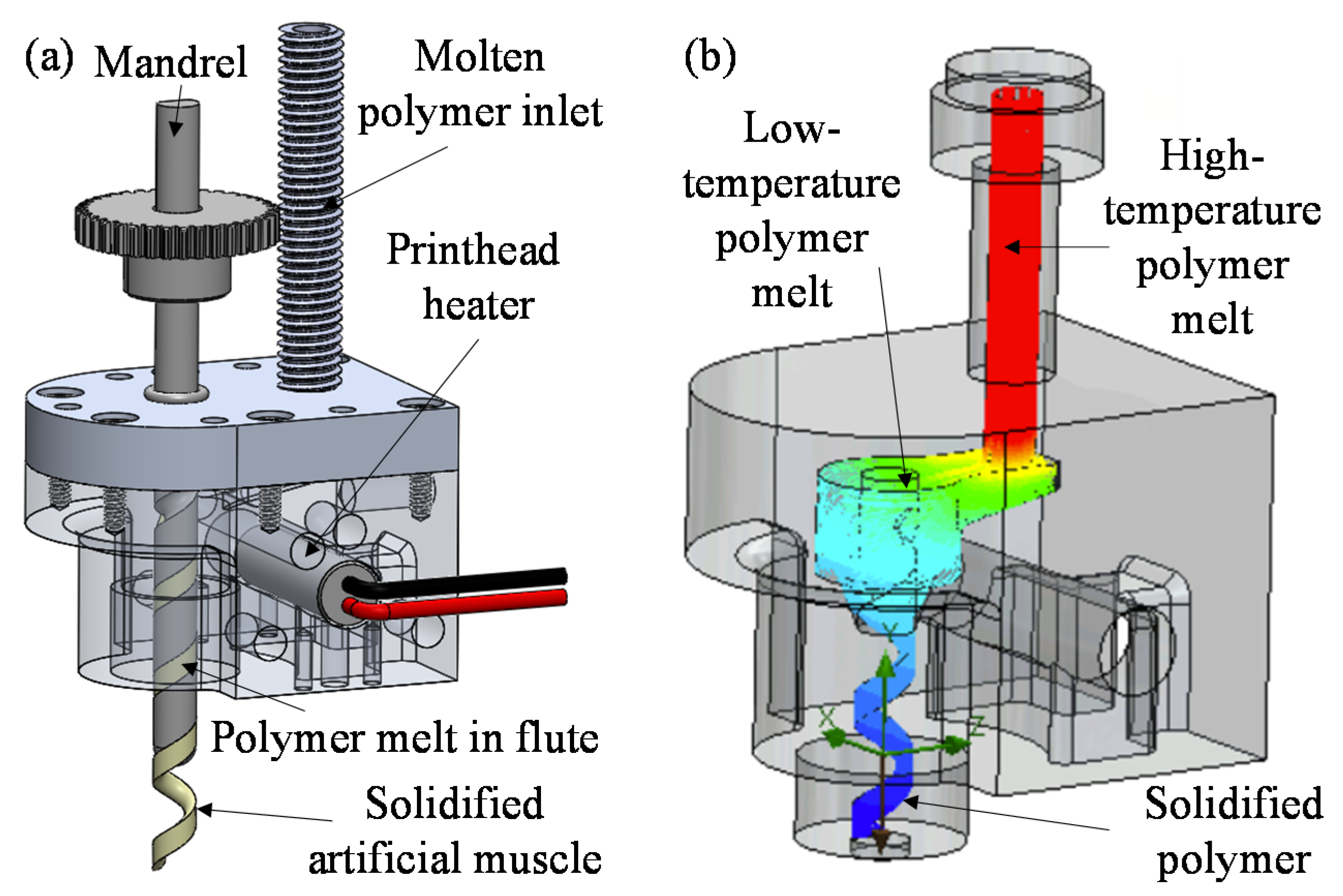
The basis of the proposed manufacturing method is to use a printhead with a helical flute, which directly determines the size and shape of generated helical SMP artificial muscles. The schematic of the printhead used in this study is illustrated in Figure 1a. Polymer melt enters the printhead through the molten polymer inlet and flows into the helical flute which is created through the interface between the printhead body and the helical channel cut into the mandrel. When the polymer melt flows through the flute, its temperature continuously decreases (as shown in Figure 1b) until the polymer is fully or partially solidified prior to exiting the printhead, resulting in the formation of a helical polymer artificial muscle. This solidification process is affected by the geometries of the helical flute coupled with the temperature distribution of the printhead, which is controlled by an embedded heater. Furthermore, polymer flow through the flute aligns the polymer chains longitudinally along the extrusion direction. For SMPs with anisotropic coefficients of thermal expansion, the alignment of the polymer chains in this manner can effectively increase the contraction force of resultant artificial muscles [24,41].
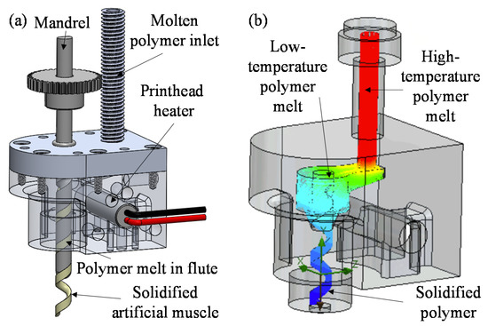
Figure 1.
(a) Schematic of the printhead with the helical flute. (b) Temperature distribution of the printhead to control polymer solidification.
2.2. Printhead Design Using Numerical Simulation
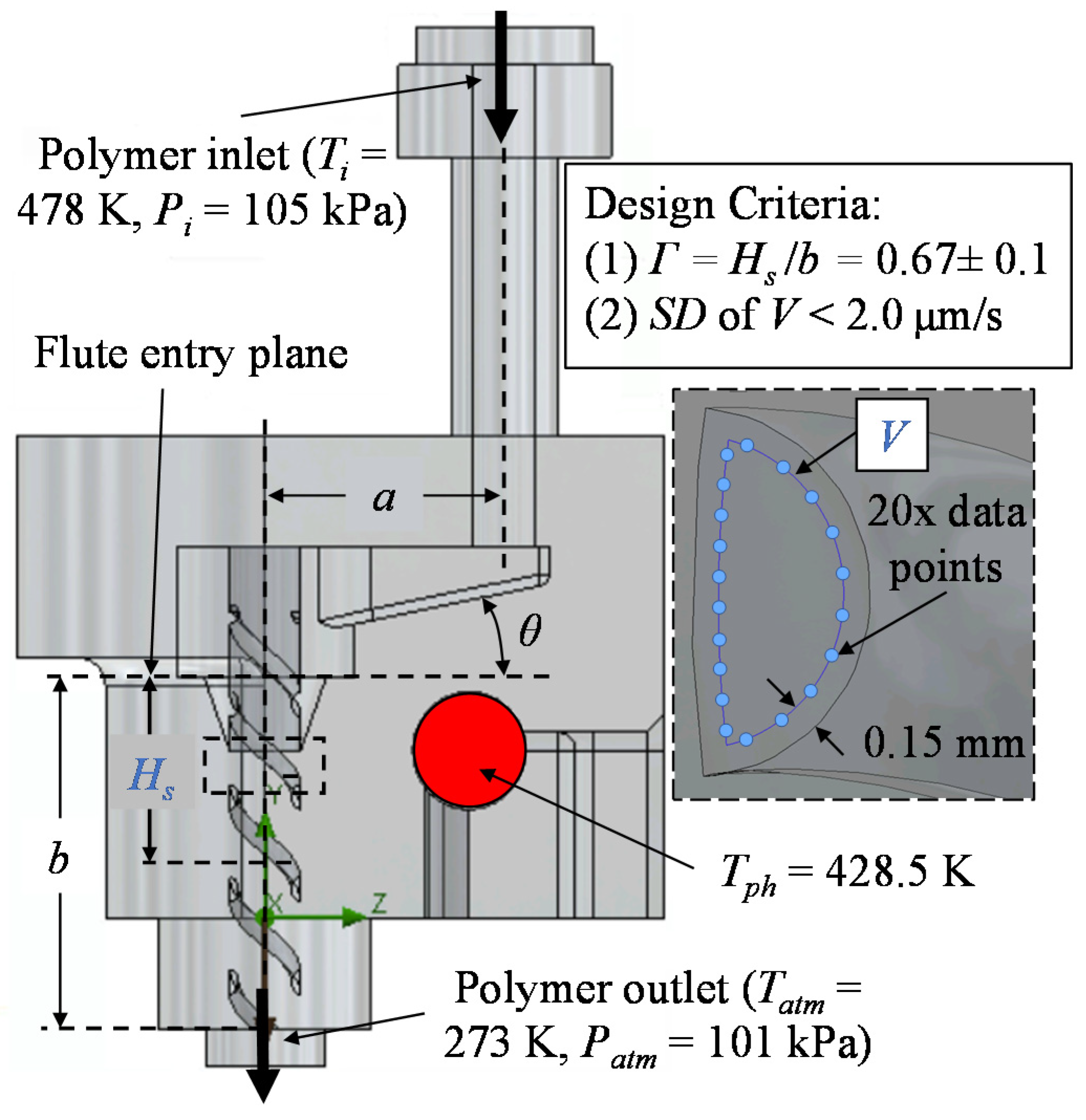
The internal structural parameters of the printhead directly affects the polymer solidification process, determining the success and accuracy of extruded SMP artificial muscles. Based on preliminary experiments, three key internal structural parameters were selected including mandrel axis length (a), inlet angle (θ), and flute length (b), as shown in Figure 2. Herein, the mandrel axis length was defined as the distance between the polymer inlet and mandrel central axes, which greatly affected solidification height (Hs). The inlet angle was defined as the angle of the sloped entrance the polymer melt must travel down to reach the inlet of the flute, which affected the flow trajectory of the polymer melt in the flute. The flute length was expressed as the distance from the flute entry plane (Figure 2) to the exit of the printhead, which was used to control the solidification process in the flute.
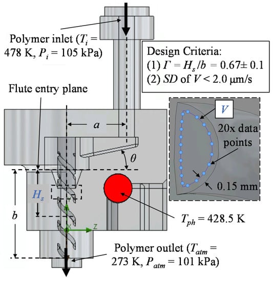
Figure 2.
Key internal structural parameters of the printhead. The design criteria are based on solidification, velocity profile, and simulation temperatures and pressures.
To determine the optimal design of the printhead, an orthogonal experimental matrix (L9 (33)) was constructed to control three levels for each key internal structural parameter as summarized in Table 1. Herein, the value of each level was determined by preliminary simulation results. SolidWorks Flow Simulation (Dassault Systèmes, Vélizy-Villacoublay, France) was used to simulate the polymer flow process through the printhead to compare the nine printhead designs in the orthogonal matrix. Two evaluation metrics were selected as shown in Figure 2: (1) the solidification ratio (Γ) of the polymer and (2) the velocity profile (V) of the molten polymer within the flute. The solidification ratio determined whether a design resulted in the desired solidification location and was calculated as the ratio of the solidification height (Hs) to the flute length (b), Γ = Hs/b, as measured from the flute entry plane. The velocity profile was critical for uniformly extruding artificial muscles and aligning polymer chains. Thus, a solidification ratio criterion of 0.67 ± 0.1 was deemed necessary for proper solidification prior to extrusion and 20 equally spaced points which were 0.15 mm from the flute wall were selected to evaluate the velocity profile of the polymer melt 5 mm below the flute entry plane (as shown in the inset of Figure 2). Using the velocity data, the standard deviation (SD) of the 20 points can be calculated for each simulation. The simulations with a velocity profile SD lower than 2 µm/s were deemed acceptable to produce continuous artificial muscles with limited surface defects. After analyzing the solidification ratios and velocity profiles of all nine designs, the optimal design of the printhead was determined.

Table 1.
Orthogonal experimental matrix for printhead design.
In the simulations, the molten SMP and the body of the printhead was set as PLA and 6061-T6 aluminum, respectively. The selection of suitable SMPs is of great significance in the proposed method because the materials must possess shape memory effects to achieve the desired linear actuation under prevalent stimuli, such as temperature change [22,23]. Herein, PLA, a widely used thermoplastic for biomedical devices, was selected as the exemplary SMP for validating the method for extruding artificial muscles in this study because of its thermal shape memory actuation properties, extrusion characteristics, and biocompatibility [32,42,43,44]. The PLA in the simulation had a melting temperature of 428 K. Due to the high operating temperature needed, 6061-T6 aluminum was chosen for its thermal and machinability characteristics to fabricate the printhead body. Additionally, all external surfaces of the printhead were assigned free convection boundary conditions to accurately depict the heat loss to the surrounding environment. A set of boundary conditions were also assigned including polymer melt inlet temperature (Ti) of 478 K, inlet pressure (Pi) of 105 kPa, printhead heater temperature (Tph) of 428.5 K, atmospheric temperature (Tatm) of 273 K, and atmospheric pressure (Patm) of 101 kPa at the exit, as shown in Figure 2.
2.3. Simulation Results
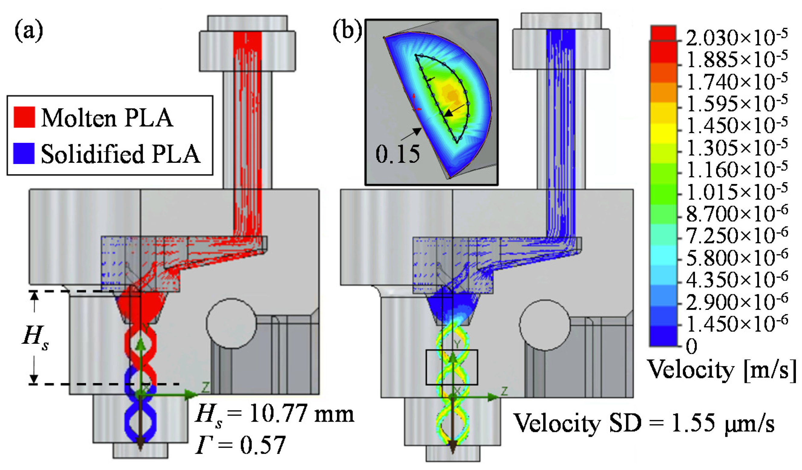
Based on the numerical simulation, solidification heights, solidification ratios and velocity profiles for all nine printhead designs were achieved as shown in Table 2. It is found that Simulations 2 and 9 contained the combinations of internal structural parameters that resulted in the solidification ratios within the desired bound of 0.67 ± 0.1 from the flute entry plane, allowing for enough time and flute length for polymer melt to solidify into the desired helical shape prior to exiting the printhead. The result of the solidification process of Simulation 2 is illustrated in Figure 3a, in which PLA above 428 K (marked in red) was at molten state as it entered the helical flute of the printhead and PLA below 428 K (marked in blue) started to solidify before exiting the printhead. Moreover, both simulations with the desired solidification ratio also had velocity profile SDs below 2 µm/s, which indicated that the geometrical combinations were acceptable for achieving uniformly distributed polymer flow within the printhead. Despite Simulation 9 resulting in a smaller velocity profile SD than Simulation 2, the printhead of Simulation 9 had a mandrel axis length (17 mm) and inlet angle (22°) larger than that of the printhead of Simulation 2 (10 mm and 11°). This increased internal space within the printhead resulted in a greater volume of polymer melt that required a higher driving pressure and a larger rate of heat transfer from the printhead heater to achieve a polymer melt flow comparable to Simulation 2. By considering the printhead overall size and energy consumption, the key internal geometries in Simulation 2 were selected for the final printhead design.

Table 2.
Simulation results.
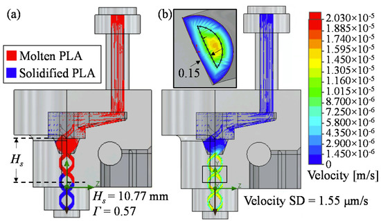
Figure 3.
(a) Solidification process and (b) velocity profile standard deviation of Simulation 2.
2.4. Analysis of Simulation Results
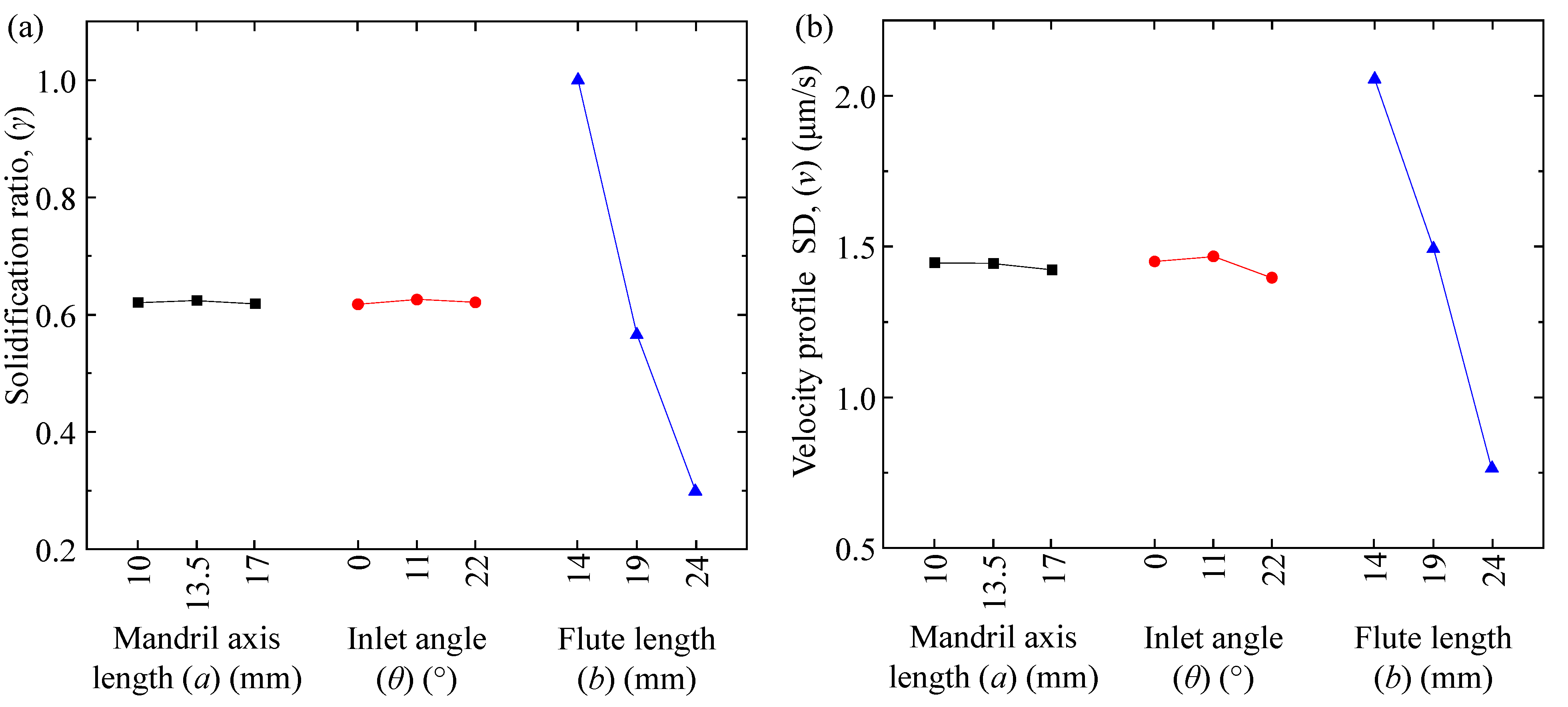
In addition to the printhead geometry selection, the orthogonal experiment results were also used to explore the combined effects of the key internal structural parameters on the solidification process and velocity distribution through a range analysis. Herein, the average value of the sum of the ith setting of variable X in each simulation was defined as miX, where m illustrated the indicators in the evaluation metrics (m = γ for solidification ratio and v for velocity profile SD, respectively), X illustrated each internal structural parameter (X = a, θ, and b as defined in Table 1), and i depicted three different values of the corresponding X (i = 1, 2, and 3). Thus, the effects of the key structural parameters on solidification ratio and velocity profile SD are summarized in Figure 4 using the calculations of γi and vi described in Table 3. As seen in Figure 4a, flute length caused the largest variation in the solidification ratio which was, therefore, most sensitive to changes in the flute length. The values of γia and γiθ were nearly constant, and thus, mandrel axis length and inlet angle did not affect the solidification ratio significantly. Similarly, changing flute length resulted in the largest variation in velocity profile SD, from 0.75 to 2.10 µm/s, as shown in Figure 4b, while there was a negligible change and minimal sensitivity when mandrel axis length or inlet angle was varied. These conclusions are also supported by the range analysis results as shown in Table 3. The range of each indicator in the evaluation metrics (RX) can be calculated by RX = Max(m1x, m2x, m3x) − Min(m1x, m2x, m3x). Thus, Rγ and Rv were calculated accordingly to gauge the sensitivity of the solidification ratio and velocity profile SD to the key internal structural parameters. From Table 3, it is found that solidification ratio was affected by all three key internal structural parameters to some degree but was most sensitive to flute length and least sensitive to mandrel axis length because Rγb >> Rγθ > Rγa. Additionally, velocity profile SD was most sensitive to flute length when compared to the other structural parameters since Rvb >> Rvθ > Rva. As a result, flute length needs to be carefully considered when designing a printhead with a helical flute, which can affect both the solidification process and flow uniformity of polymer melt in the flute. Although mandrel axis length and inlet angle present negligible effects on the solidification ratio and velocity profile SD, they do affect the solidification height (as shown in Table 2) by greatly altering flow trajectory, position from the printhead heater, and distance from polymer melt inlet to the ideal solidification zone of the flute, which further impact the overall size of the printhead design. Therefore, all key internal structural parameters must be fully considered during the printhead design process.
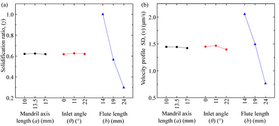
Figure 4.
Coupling effects of mandrel axis length, inlet angle, and flute length on (a) solidification ratio and (b) velocity profile SD.

Table 3.
Analysis of coupling effects and range analysis of orthogonal experiments.
2.5. Material Extrusion System Design
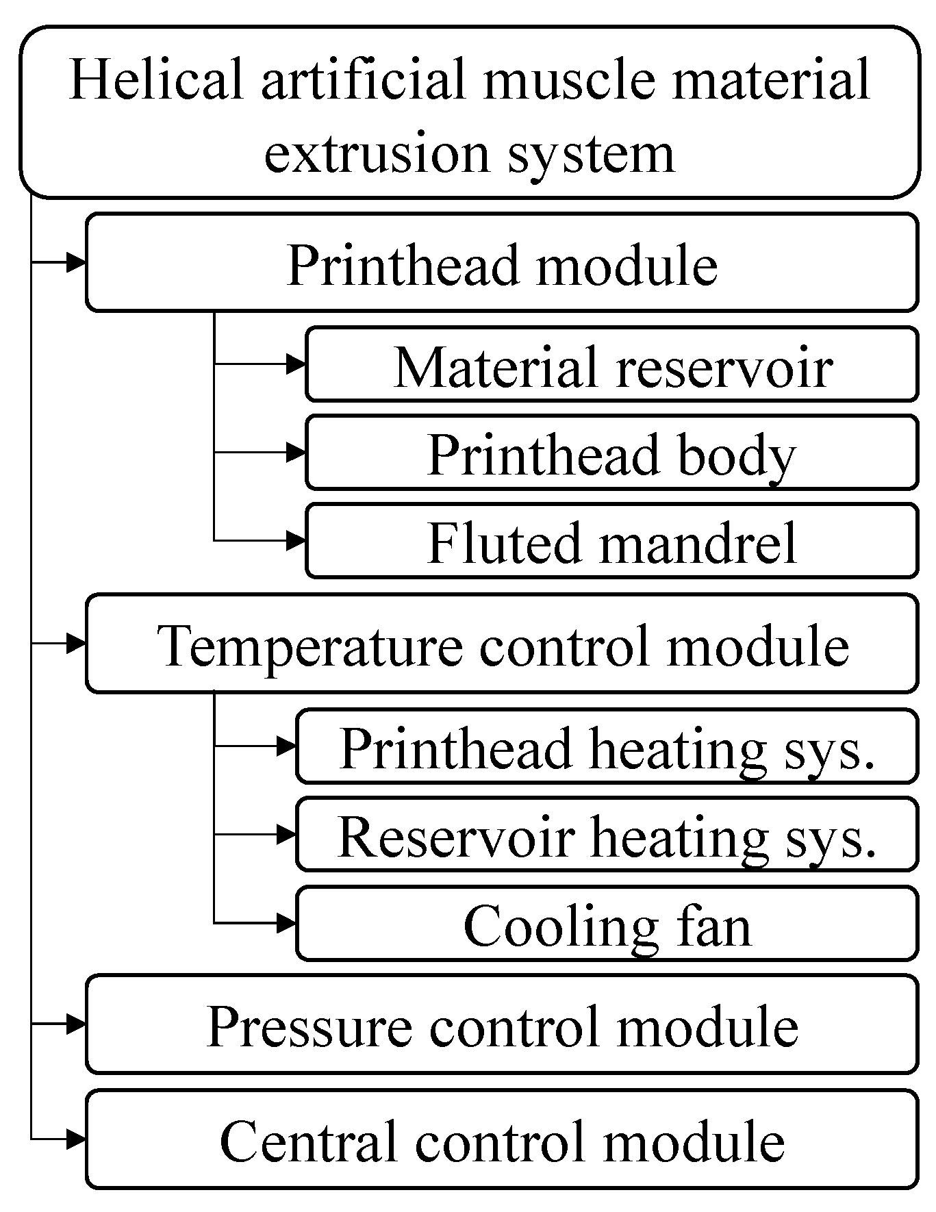
In addition to the printhead and helical fluted mandrel, other auxiliary components were needed to achieve controlled solidification of polymer melt within the printhead and form helical artificial muscles. The material extrusion system in this work was composed of the following modules: (1) printhead module which consisted of a printhead using the geometries of the selected optimal design and a material reservoir to continuously store and feed SMP to the printhead; (2) temperature control module which was composed of a printhead heating system to increase the temperature of the printhead, a reservoir heating system to ensure the SMP at molten state before entering the printhead, and a cooling fan to adjust the cooling speed of polymer melt in the flute; (3) pressure control module to pneumatically push polymer melt from the material reservoir and into the printhead to further control the extrusion speed; and (4) central control module to control angular position of the mandrel for future 3D printing research. The framework of the material extrusion system for manufacturing helical artificial muscles from an SMP is illustrated in Figure 5.
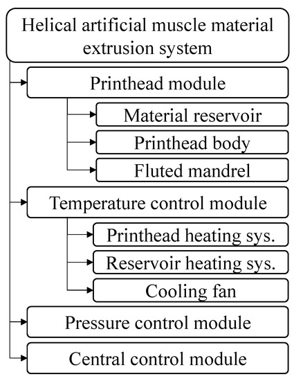
Figure 5.
Framework of the helical artificial muscle material extrusion system.
2.6. Experimental Setup
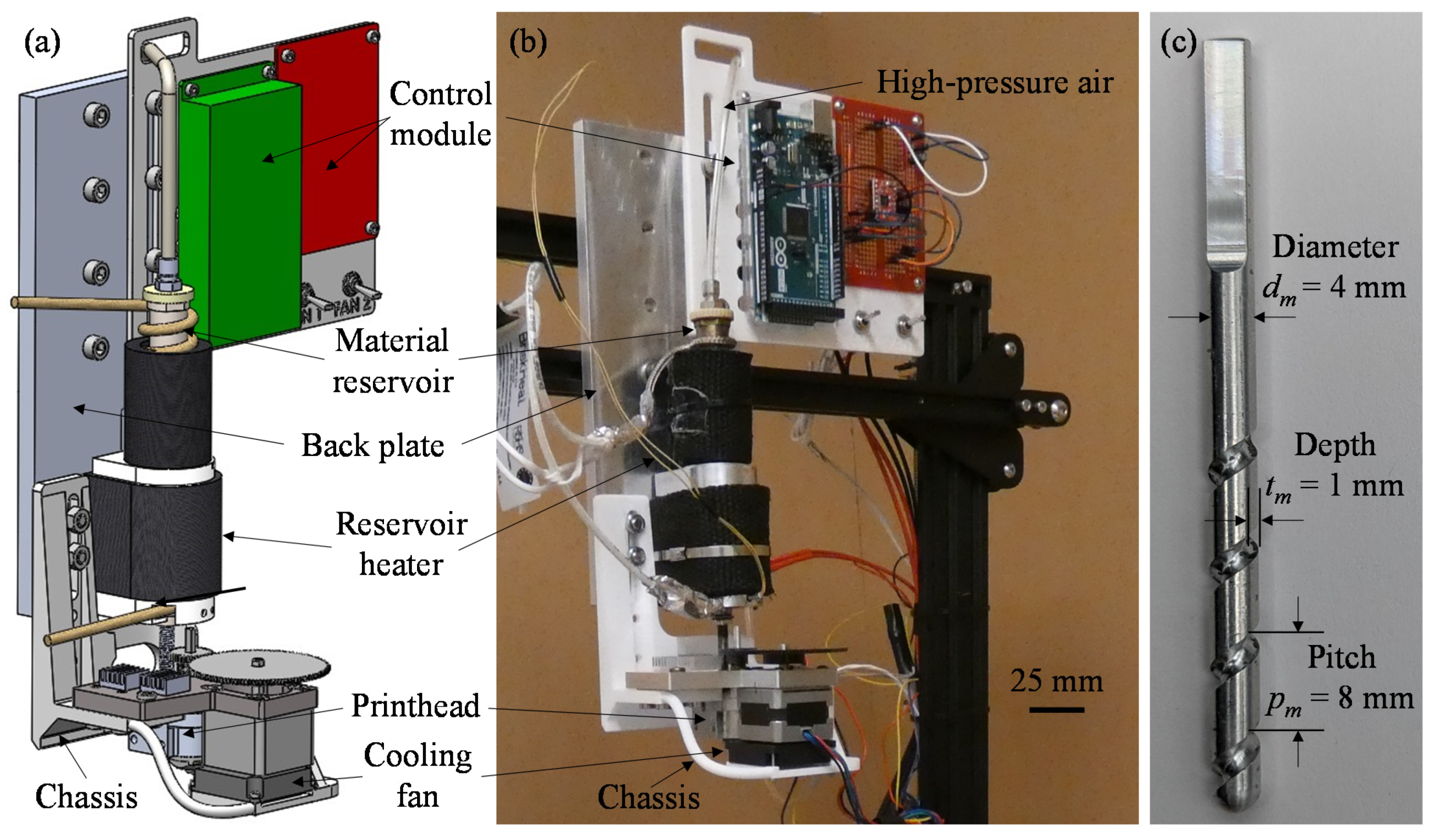
Upon completion of numerical simulation and system design, all components of the material extrusion system were created and assembled using SOLIDWORKS 2022 (Dassault Systèmes, Vélizy-Villacoublay, France) as shown in Figure 6a, and then manufactured and set up as shown in Figure 6b. Particularly, the components to construct the printhead including the printhead body and the fluted mandrel were fabricated from 6061-T6 aluminum (9146T84, McMaster-Carr, Robbinsville, NJ, USA) in the machine shop of the Department of Mechanical Engineering at the University of Nevada, Reno using the geometries dictated by Simulation 2. The mandrel as depicted in Figure 6c had the diameter (dm) of 4 mm, flute depth (tm) of 1 mm, and flute pitch (pm) of 8 mm. The stainless-steel material reservoir was purchased from CELLINK (CSA000000012, CELLINK LLC, Boston, MA, USA) and included the pneumatic piston and high-pressure air connection terminals needed to drive the polymer melt flow. The printhead heating system included a cylindrical cartridge heater (HR25010L, BriskHeat, Columbus, OH, USA) and a heat controller (SDXRA, BriskHeat, Columbus, OH, USA), while the reservoir heating system consisted of a high temperature heating cord (HWC1040, BriskHeat, Columbus, OH, USA) and a heat controller (SDCERA, BriskHeat, Columbus, OH, USA), which were used to control the temperatures of the printhead and reservoir separately. A cooling fan (CR-B-Fan, Creality 3D, Shenzhen, China) was incorporated into the printhead system, which was located at the end of the printhead to aid in the polymer solidification process. A voltage to pressure converter (EP211-X120-10V, Omega, Norwalk, CT, USA) was used to adjust the inlet pressure acting on the pneumatic piston inside the material reservoir to induce polymer melt flowing into the printhead. The central control module was composed of a controller (Mega2560 Rev3, Arduino, Somerville, MA, USA) and a stepper motor driver (A4988, HiLetgo, Shenzhen, China), both of which were used to control the rotation and radial position of the mandrel via a NEMA-14 stepper motor (14HS10-0404S, Stepperonline Inc., New York, NY, USA) to aid in future investigations of 3D printing artificial muscle groups. Finally, a printhead chassis, fabricated from nylon 12 using selective laser sintering (Xometry, Gaithersburg, MD, USA), and a machined 6061-T6 aluminum back plate were designed to accurately mate all previously mentioned modules/systems/components to the gantry of a CR-10 (Creality, Shenzhen, China) 3D printer.
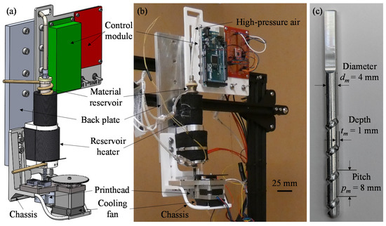
Figure 6.
(a) Schematic and (b) setup of the artificial muscle material extrusion system. (c) Fluted mandrel with key dimensions.
3. Artificial Muscle Extrusion and Contraction Experiments
3.1. Materials and Methods
Luminy LX175 PLA pellets (TotalEnergies Corbion, Amsterdam, The Netherlands) were used as the SMP in this work. For artificial muscle extrusion experiments, PLA pellets were first fed into the material reservoir. The temperature of the reservoir was increased to 215 °C and held for 10 min to completely melt PLA pellets and remove air bubbles from the polymer melt. Then, the high-pressure air (~68.9 kPa) was applied to push the polymer melt from the reservoir into the printhead, which was heated to the extrusion temperature of 130 °C. Simultaneously, the cooling fan was turned on to 75% of its total fan speed of 11.7 m/s to increase the localized cooling within the flute. At the exit of the printhead, an extruded continuous helical filament was collected as the SMP artificial muscle. The key extrusion process parameters are summarized in Table 4. After extrusion, the outer diameter (d), pitch (p), and thickness (t) of the helical filament were measured using a high-precision measurement system (Vertex 261 Micro-Vu, Windsor, CA, USA) and its metrology software, InSpec 2.104.3 (Micro-Vu, Windsor, CA, USA).

Table 4.
Key process parameters in artificial muscle extrusion.
The fabricated helical filament was programmed and contracted to validate the ability of the proposed printhead to fabricate SMP artificial muscles. Before programming, each helical filament was cut to a target length of 74 mm. After cutting, the actual length of the filament was measured as lo. To program the helical filament, a 150-watt heat lamp (Feit Electric, Pico Rivera, CA, USA) was first used and carefully adjusted to uniformly increase the temperature of the filament to 65 °C. After holding the filament at this temperature for 5 min, a tensile machine (eXpert 7600; ADMET, Norwood, MA, USA) was applied to elongate the heated filament at a speed of 2.5 mm/min until the filament reached a normal strain (ε = (le − lo)/lo, where le is the filament length after elongation) of 7.5%. Then, the filament was held under elongation and heat for 2 min for programming. After that, the ambient temperature was decreased to room temperature and the length of the programmed filament was measured. To induce contraction, the filament was uniformly heated to 70 °C using the heat lamp for 1.5 min. Then, the final length (lc) of the filament was measured. The length recovery ratio (r) can be calculated using the equation: r = (le − lc)/(le − lo) × 100%. The contraction experiment was repeated three times for testing and analyzing the contraction repeatability of the fabricated artificial muscles.
3.2. Results and Discussion
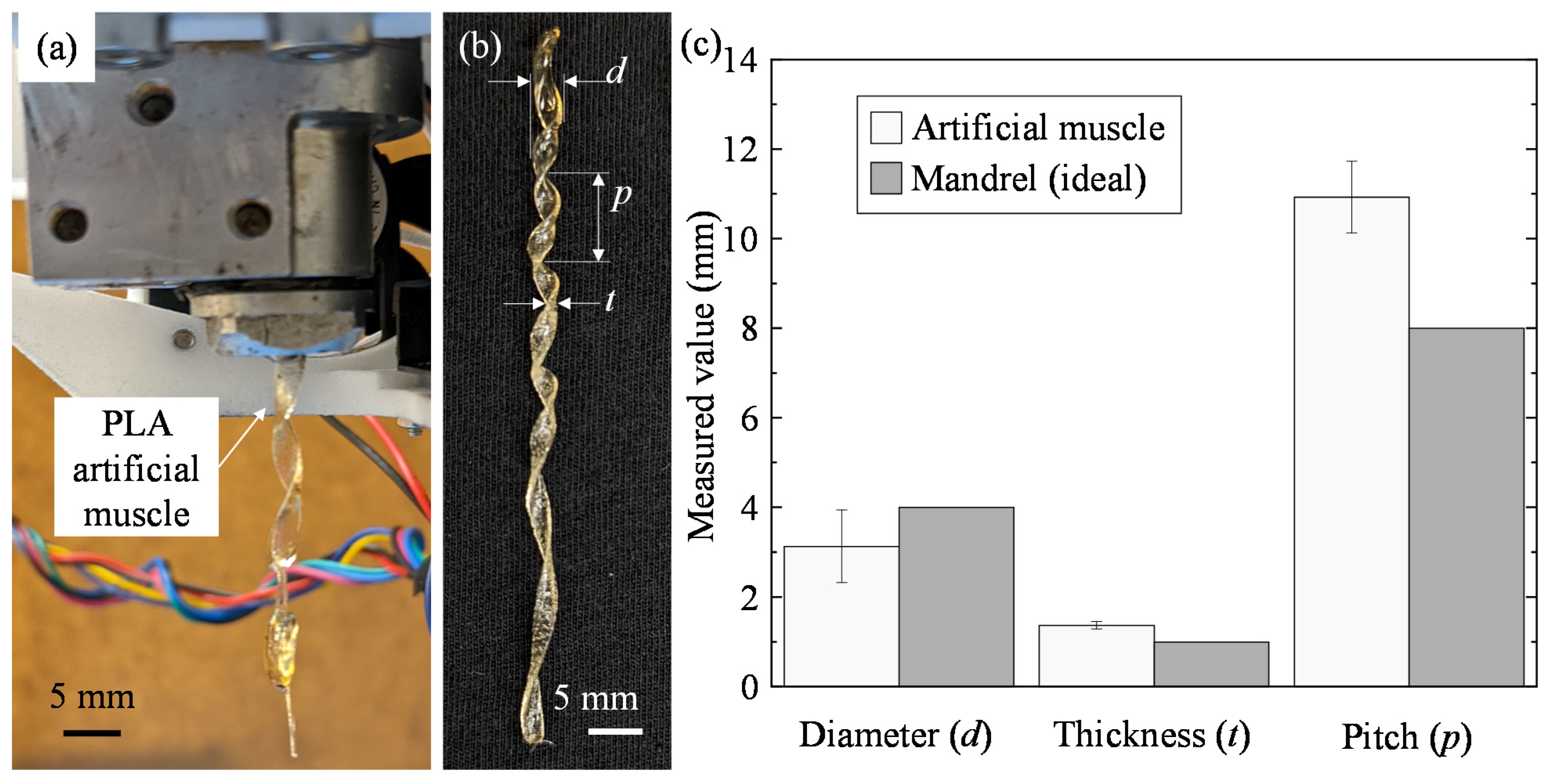
Using the proposed material extrusion system, a PLA helical filament was successfully extruded as shown in Figure 7a. The polymer melt was shaped and supported by the helical flute and nearly solidified prior to extrusion to effectively maintain the helical shape as designed. A representative helical filament as an artificial muscle is illustrated in Figure 7b. The key dimensions including average diameter, pitch, and thickness were measured as 3.51 ± 0.81 mm, 1.28 ± 0.08 mm, and 10.83 ± 0.80 mm, respectively. By comparing the measured dimensions with the structural parameters of the fluted mandrel (Figure 7c), it was found that the fabricated artificial muscle had a diameter slightly smaller than the mandrel diameter (4.0 mm), while both the thickness and pitch were larger than the flute depth (1.0 mm) and pitch (8.0 mm) of the mandrel. The slight increase in the artificial muscle thickness can be attributed to the die swelling phenomenon during extrusion [45,46]. At the exit, the polymer melt is partially solidified but retains viscoelastic and fluidlike properties, allowing the filament to expand in thickness as it exits the printhead, which results in the larger thickness after solidification. Since die swelling depends on the flow rate and viscoelasticity of the extruding fluid [46,47], it is technically feasible to reduce the artificial muscle thickness to better match the flute size by decreasing the inlet pressure to slow polymer melt flow or selecting an SMP with lower viscoelasticity. The difference in pitch between the measured artificial muscle and the mandrel is mainly caused by the weight of the extruding filament acting on the partially solidified PLA, in which the filament is gradually elongated prior to full solidification. Self-gravity also results in the pitch variation, as shown in Figure 7a: the last extruded section of the filament presents a larger pitch due to gravity-induced localized elongation at the printhead’s exit. This pitch variation may lead to non-uniform mechanical properties of the fabricated artificial muscle. The gravity-induced elongation also causes the decrease in diameter since the volume of extruded filament is constant. There are two potential solutions to improve the dimensional accuracy. One is to speed up the solidification of extruded filaments at the printhead’s exit by increasing the fan speed. Another is to deposit filaments into a water bath, using buoyancy force to eliminate the self-gravity effects. Although the measured dimensions are different from those of the fluted mandrel, the relative errors are still acceptable: ~13% for the diameter, ~28% for the thickness, and ~25% for the pitch, indicating the effectiveness of the proposed method for fabricating SMP artificial muscles with a helical shape.
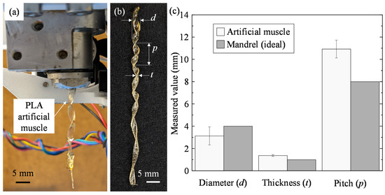
Figure 7.
(a) Helical artificial muscle extrusion. (b) Extruded artificial muscle with key dimensions: muscle diameter (d), thickness (t), and pitch (p). (c) Comparison between the measured dimensions and the key dimensions of the fluted mandrel.
PLA is a commonly used polymer with a programmable shape memory effect [42,43] allowing for a simple validation for the printhead design and fabrication process to manufacture helical artificial muscles. To actuate PLA as a contracting artificial muscle, the extruded helical filament must be subjected to a tension force while also held at a temperature above the glass transition temperature and below the melting temperature [42]. The PLA used in this study was a commercially available product (Luminy LX175, TotalEnergies Corbion, The Netherlands) with a well-documented glass transition temperature of 60 °C and melting temperature of 155 °C [48,49,50]. Therefore, 65 °C was selected as the temperature to program the PLA artificial muscle under tension.
Before programming, the original length of the artificial muscle was measured as 72.9 mm, as shown in Figure 8a. Then, the artificial muscle was heated to 65 °C and extended to a length of 78.8 mm as depicted in Figure 8b. After cooling at this extended status, the artificial muscle was successfully programmed. Finally, the ambient temperature was increased to ~70 °C to trigger the contraction of the artificial muscle, leading to a decrease in length to 74.1 mm, as shown in Figure 8c. The length recovery ratio was found to be 79.7%. After repeating the programming-contraction cycle for the second and third times, the corresponding length recovery ratios were measured as 75.7% and 60.0%, respectively. The programmability, contraction, and acceptable recovery ratios for multiple cycles verify the ability of the printhead to fabricate helical artificial muscles with excellent shape memory characteristics.

Figure 8.
Artificial muscle (a) before deformation and (b) deformation at 65 °C. (c) Contraction of the programmed artificial muscle at 70 °C.
4. Conclusions and Future Work
The compact and user-friendly printhead was designed and built in this study to fabricate helical SMP artificial muscles. The printhead used a helical internal flute to shape and support polymer melt during extrusion, nullifying the need for external supports or any form of receiving substrates. To select the optimal design, a numerical simulation was performed based on the orthogonal experimental matrix, which was also used to comprehensively evaluate the coupling effects of the key internal structural parameters on the solidification process and polymer melt flow uniformity in the helical flute. It was found that both solidification ratio and velocity profile SD were most sensitive to the variation of flute length when compared to the changes to mandrel axis length or inlet angle. After determining the optimal design, the printhead and the material extrusion system were established and mated to a commercial 3D printing platform to successfully extrude helical PLA filaments as artificial muscles. By comparing key dimensions of the artificial muscle with the dimensions of the flute, it was found that the thickness and pitch of the extruded artificial muscle were oversized while the diameter was undersized. Finally, a high length recovery ratio of 79.7% was achieved after performing the contraction experiment of the artificial muscle, which effectively validates the printhead’s ability to fabricate artificial muscles from SMPs.
Future work includes investigations focusing on the effects of operating parameters and mandrel geometries on the formation of artificial muscles and key structural dimensions. Since the main focus of this work is to test the feasibility of directly extruding artificial muscles using the printhead, the mechanical properties of extruded filaments are not provided. In the future, some key mechanical properties, such as elastic modulus, ultimate tensile strength, and failure strain, will be comprehensively characterized to further evaluate the fabricated artificial muscles. In addition, how to overcome self-gravity of extruded artificial muscles is another challenge, which can greatly improve the shape accuracy and uniformity of mechanical properties of products. Thus, the potential solutions to eliminate self-gravity effects will be tested in the future. Moreover, two-way SMPs, such as poly(cyclooctene), poly(ε-caprolactone), poly(ester urethane), poly(ethylene-co-vinyl acetate), and more [20,21,25,51,52,53,54,55], will be studied in the future as the build material to make artificial muscles using the proposed method and system, which can repeatedly switch between elongation and contraction states to provide on-demand tension forces for biomedical devices.
Author Contributions
K.M.: Conceptualization, Methodology, Formal analysis, Investigation, Writing—Original Draft. L.R.: Conceptualization, Methodology, Formal analysis, Writing—Review and Editing. Y.J.: Conceptualization, Writing—Review and Editing, Supervision, and Project Administration. All authors have read and agreed to the published version of the manuscript.
Funding
The research was funded by the Nevada NASA Space Grant Consortium, grant number: AWD-01-00003025.
Institutional Review Board Statement
Not applicable.
Informed Consent Statement
Not applicable.
Data Availability Statement
Not applicable.
Acknowledgments
The authors fully appreciate the financial supports from the Nevada NASA Space Grant Consortium. Y.J. acknowledges Jun Zhang at the University of Nevada, Reno and Ji Su at the NASA Langley Research Center for their supports in this study.
Conflicts of Interest
The authors declare no conflict of interest.
References
- Kumar, R.; Lim, J.; Mekary, R.A.; Rattani, A.; Dewan, M.C.; Sharif, S.Y.; Osorio-Fonseca, E.; Park, K.B. Traumatic spinal injury: Global epidemiology and worldwide volume. World Neurosurg. 2018, 113, e345–e363. [Google Scholar] [CrossRef] [PubMed]
- Tysnes, O.B.; Storstein, A. Epidemiology of Parkinson’s disease. J. Neural. Transm. 2017, 124, 901–905. [Google Scholar] [CrossRef] [PubMed]
- Yun, S.J.; Lee, H.H.; Lee, W.H.; Lee, S.H.; Oh, B.M.; Seo, H.G. Effect of robot-assisted gait training on gait automaticity in Parkinson disease: A prospective, open-label, single-arm, pilot study. Medicine 2021, 100, e24348. [Google Scholar] [CrossRef] [PubMed]
- Meijneke, C.; van Oort, G.; Sluiter, V.; van Asseldonk, E.; Tagliamonte, N.L.; Tamburella, F.; Pisotta, I.; Masciullo, M.; Arquilla, M.; Molinari, M.; et al. Symbitron exoskeleton: Design, control, and evaluation of a modular exoskeleton for incomplete and complete spinal cord injured individuals. IEEE Trans. Neural. Syst. Rehabil. Eng. 2021, 29, 330–339. [Google Scholar] [CrossRef]
- Nassour, J.; Zhao, G.; Grimmer, M. Soft pneumatic elbow exoskeleton reduces the muscle activity, metabolic cost and fatigue during holding and carrying of loads. Sci. Rep. 2021, 11, 12556. [Google Scholar] [CrossRef]
- Park, S.J.; Park, C.H. Suit-type wearable robot powered by shape-memory-alloy-based fabric muscle. Sci. Rep. 2019, 9, 9157. [Google Scholar] [CrossRef] [Green Version]
- Peele, B.N.; Wallin, T.J.; Zhao, H.; Shepherd, R.F. 3D printing antagonistic systems of artificial muscle using projection stereolithography. Bioinspir. Biomim. 2015, 10, 055003. [Google Scholar] [CrossRef]
- Sangian, D.; Jeiranikhameneh, A.; Naficy, S.; Beirne, S.; Spinks, G.M. Three-dimensional printed braided sleeves for manufacturing mcKibben artificial muscles. 3D Print. Addit. Manuf. 2019, 6, 57–62. [Google Scholar] [CrossRef]
- Tawk, C.; In Het Panhuis, M.; Spinks, G.M.; Alici, G. Bioinspired 3D printable soft vacuum actuators for locomotion robots, grippers and artificial muscles. Soft Robot. 2018, 5, 685–694. [Google Scholar] [CrossRef]
- Uribe-Gomez, J.; Schönfeld, D.; Posada-Murcia, A.; Roland, M.M.; Caspari, A.; Synytska, A.; Salehi, S.; Pretsch, T.; Ionov, L. Fibrous scaffolds for muscle tissue engineering based on touch-spun poly (ester-urethane) elastomer. Macromol. Biosci. 2022, 22, 2100427. [Google Scholar] [CrossRef]
- Cakal, S.D.; Radeke, C.; Alcala, J.F.; Ellman, D.G.; Butdayev, S.; Andersen, D.C.; Calloe, K.; Lind, J.U. A simple and scalable 3D printing methodology for generating aligned and extended human and murine skeletal muscle tissues. Biomed. Mater. 2022, 17, 045013. [Google Scholar] [CrossRef] [PubMed]
- Russell, C.S.; Mostafavi, A.; Quint, J.P.; Panayi, A.C.; Baldino, K.; Williams, T.J.; Daubendiek, J.G.; Hugo Sánchez, V.; Bonick, Z.; Trujillo-Miranda, M. In situ printing of adhesive hydrogel scaffolds for the treatment of skeletal muscle injuries. ACS Appl. Bio. Mater. 2020, 3, 1568–1579. [Google Scholar] [CrossRef] [PubMed]
- Dong, R.; Ma, P.X.; Guo, B. Conductive biomaterials for muscle tissue engineering. Biomaterials 2020, 229, 119584. [Google Scholar] [CrossRef] [PubMed]
- Mirvakili, S.M.; Hunter, I.W. Fast torsional artificial muscles from NiTi twisted yarns. ACS Appl. Mater. Interfaces 2017, 9, 16321–16326. [Google Scholar] [CrossRef]
- Villoslada, A.; Flores, A.; Copaci, D.; Blanco, D.; Moreno, L. High-displacement flexible shape memory alloy actuator for soft wearable robots. Robot. Auton. Syst. 2015, 73, 91–101. [Google Scholar] [CrossRef]
- Carrico, J.D.; Kim, K.J.; Leang, K.K. 3D-printed ionic polymer-metal composite soft crawling robot. In Proceedings of the 2017 IEEE International Conference on Robotics and Automation (ICRA), Singapore, 29 May–3 June 2017; pp. 4313–4320. [Google Scholar] [CrossRef]
- Maksimkin, A.V.; Kaloshkin, S.D.; Zadorozhnyy, M.V.; Senatov, F.S.; Salimon, A.I.; Dayyoub, T. Artificial muscles based on coiled UHMWPE fibers with shape memory effect. Express Polym. Lett. 2018, 12, 1072–1080. [Google Scholar] [CrossRef]
- Yang, Y.; Chen, Y.; Wei, Y.; Li, Y. 3D printing of shape memory polymer for functional part fabrication. Int. J. Adv. Manuf. Technol. 2015, 84, 2079–2095. [Google Scholar] [CrossRef]
- Peng, X.; He, H.; Jia, Y.; Liu, H.; Geng, Y.; Huang, B.; Luo, C. Shape memory effect of three-dimensional printed products based on polypropylene/nylon 6 alloy. J. Mater. Sci. 2019, 54, 9235–9246. [Google Scholar] [CrossRef]
- Fan, J.; Li, G. High performance and tunable artificial muscle based on two-way shape memory polymer. RSC Adv. 2017, 7, 1127–1136. [Google Scholar] [CrossRef] [Green Version]
- Chen, Y.; Chen, C.; Rehman, H.U.; Zheng, X.; Li, H.; Liu, H.; Hedenqvist, M.S. Shape-memory polymeric artificial muscles: Mechanisms, applications and challenges. Molecules 2020, 25, 4246. [Google Scholar] [CrossRef]
- Haines, C.S.; Lima, M.D.; Li, N.; Spinks, G.M.; Foroughi, J.; Madden, J.D.; Kim, S.H.; Fang, S.; Jung de Andrade, M.; Goktepe, F.; et al. Artificial muscles from fishing line and sewing thread. Science 2014, 343, 868–872. [Google Scholar] [CrossRef] [PubMed]
- Tsabedze, T.; Mullen, C.; Coulter, R.; Wade, S.; Zhang, J. Helically wrapped supercoiled polymer (HW-SCP) artificial muscles: Design, characterization, and modeling. In Proceedings of the 2020 IEEE International Conference on Robotics and Automation (ICRA), Paris, France, 31 May–31 August 2020; pp. 5862–5868. [Google Scholar] [CrossRef]
- Choy, C.; Chen, F.; Young, K. Negative thermal expansion in oriented crystalline polymers. J. Polym. Sci. Polym. Phys. Ed. 1981, 19, 335–352. [Google Scholar] [CrossRef]
- Dai, L.; Song, J.; Qu, S.; Xiao, R. Triple-shape memory effect in 3D-printed polymers. eXPRESS Polym. Lett. 2020, 14, 1116–1126. [Google Scholar] [CrossRef]
- Lee, A.Y.; An, J.; Chua, C.K. Two-way 4D printing: A review on the reversibility of 3D-printed shape memory materials. Engineering 2017, 3, 663–674. [Google Scholar] [CrossRef]
- Estelle, K.; Blair, D.; Evans, K.; Gozen, B.A. Manufacturing of smart composites with hyperelastic property gradients and shape memory using fused deposition. J. Manuf. Processes 2017, 28, 500–507. [Google Scholar] [CrossRef]
- Wang, X.; Qin, X.-H.; Hu, C.; Terzopoulou, A.; Chen, X.-Z.; Huang, T.-Y.; Maniura-Weber, K.; Pané, S.; Nelson, B.J. 3D printed enzymatically biodegradable soft helical microswimmers. Adv. Funct. Mater. 2018, 28, 1804107. [Google Scholar] [CrossRef]
- Lv, C.; Sun, X.-C.; Xia, H.; Yu, Y.-H.; Wang, G.; Cao, X.-W.; Li, S.-X.; Wang, Y.-S.; Chen, Q.-D.; Yu, Y.-D.; et al. Humidity-responsive actuation of programmable hydrogel microstructures based on 3D printing. Sens. Actuators B Chem. 2018, 259, 736–744. [Google Scholar] [CrossRef]
- Mirvakili, S.M.; Hunter, I.W. Artificial muscles: Mechanisms, applications, and challenges. Adv. Mater. 2018, 30, 1704407. [Google Scholar] [CrossRef]
- Yamada, A.; Niikura, F.; Ikuta, K. A three-dimensional microfabrication system for biodegradable polymers with high resolution and biocompatibility. J. Micromech. Microeng. 2008, 18, 25035. [Google Scholar] [CrossRef]
- Zhao, D.; Zhou, R.; Sun, J.; Li, H.; Jin, Y. Experimental study of polymeric stent fabrication using homemade 3D printing system. Polym. Eng. Sci. 2019, 59, 1122–1131. [Google Scholar] [CrossRef]
- Lebel, L.L.; Aissa, B.; El Khakani, M.A.; Therriault, D. Ultraviolet-assisted direct-write fabrication of carbon nanotube/polymer nanocomposite microcoils. Adv. Mater. 2010, 22, 592–596. [Google Scholar] [CrossRef] [PubMed]
- Li, V.C.-F.; Kuang, X.; Hamel, C.M.; Roach, D.; Deng, Y.; Qi, H.J. Cellulose nanocrystals support material for 3D printing complexly shaped structures via multi-materials-multi-methods printing. Addit. Manuf. 2019, 28, 14–22. [Google Scholar] [CrossRef]
- Chueca de Bruijn, A.; Gómez-Gras, G.; Pérez, M.A. Mechanical study on the impact of an effective solvent support-removal methodology for FDM Ultem 9085 parts. Polym. Test. 2020, 85, 106433. [Google Scholar] [CrossRef]
- Roach, D.J.; Yuan, C.; Kuang, X.; Li, V.C.; Blake, P.; Romero, M.L.; Hammel, I.; Yu, K.; Qi, H.J. Long liquid crystal elastomer fibers with large reversible actuation strains for smart textiles and artificial muscles. ACS Appl. Mater. Interfaces 2019, 11, 19514–19521. [Google Scholar] [CrossRef]
- Jin, Y.; Compaan, A.; Bhattacharjee, T.; Huang, Y. Granular gel support-enabled extrusion of three-dimensional alginate and cellular structures. Biofabrication 2016, 8, 025016. [Google Scholar] [CrossRef] [Green Version]
- Jin, Y.; Compaan, A.; Chai, W.; Huang, Y. Functional nanoclay suspension for printing-then-solidification of liquid materials. ACS Appl. Mater. Interfaces 2017, 9, 20057–20066. [Google Scholar] [CrossRef]
- Skylar-Scott, M.A.; Uzel, S.G.; Nam, L.L.; Ahrens, J.H.; Truby, R.L.; Damaraju, S.; Lewis, J.A. Biomanufacturing of organ-specific tissues with high cellular density and embedded vascular channels. Sci. Adv. 2019, 5, eaaw2459. [Google Scholar] [CrossRef] [Green Version]
- Bayaniahangar, R.; Bayani Ahangar, S.; Zhang, Z.; Lee, B.P.; Pearce, J.M. 3-D printed soft magnetic helical coil actuators of iron oxide embedded polydimethylsiloxane. Sens. Actuators B Chem. 2021, 326, 128781. [Google Scholar] [CrossRef]
- Yang, Q.; Fan, J.; Li, G. Artificial muscles made of chiral two-way shape memory polymer fibers. Appl. Phys. Lett. 2016, 109. [Google Scholar] [CrossRef]
- Wu, W.; Ye, W.; Wu, Z.; Geng, P.; Wang, Y.; Zhao, J. Influence of layer thickness, raster angle, deformation temperature and recovery temperature on the shape-memory effect of 3D-printed polylactic acid samples. Materials 2017, 10, 970. [Google Scholar] [CrossRef] [Green Version]
- Zare, M.; Prabhakaran, M.P.; Parvin, N.; Ramakrishna, S. Thermally-induced two-way shape memory polymers: Mechanisms, structures, and applications. Chem. Eng. J. 2019, 374, 706–720. [Google Scholar] [CrossRef]
- Chen, X.; Chen, G.; Wang, G.; Zhu, P.; Gao, C. Recent progress on 3D-printed polylactic acid and its applications in bone repair. Adv. Eng. Mater. 2019, 22, 1901065. [Google Scholar] [CrossRef]
- Serdeczny, M.P.; Comminal, R.; Pedersen, D.B.; Spangenberg, J. Experimental and analytical study of the polymer melt flow through the hot-end in material extrusion additive manufacturing. Addit. Manuf. 2020, 32, 100997. [Google Scholar] [CrossRef]
- Xia, H.; Lu, J.; Tryggvason, G. A numerical study of the effect of viscoelastic stresses in fused filament fabrication. Computer Methods Appl. Mech. Eng. 2019, 346, 242–259. [Google Scholar] [CrossRef]
- Liang, J.-Z. Melt die-swell behavior of polyoxymethylene blended with ethylene-vinyl acetate copolymer and high-density polyethylene. Polymer Test. 2018, 68, 213–218. [Google Scholar] [CrossRef]
- Aversa, C.; Barletta, M.; Gisario, A.; Pizzi, E.; Prati, R.; Vesco, S. Corotating twin-screw extrusion of poly (lactic acid) PLA/poly (butylene succinate) PBS/micro-lamellar talc blends for extrusion blow molding of biobased bottles for alcoholic beverages. J. Appl. Polym. Sci. 2021, 138, 51294. [Google Scholar] [CrossRef]
- Luoma, E.; Välimäki, M.; Rokkonen, T.; Sääskilahti, H.; Ollila, J.; Rekilä, J.; Immonen, K. Oriented and annealed poly (lactic acid) films and their performance in flexible printed and hybrid electronics. J. Plast. Film Sheeting 2021, 37, 429–462. [Google Scholar] [CrossRef]
- Kaczor, D.; Bajer, K.; Domek, G.; Raszkowska-Kaczor, A.; Szroeder, P. The method of obtaining polymer masterbatches based on polylactide with carbon filler. In Proceedings of the IOP Conference Series: Materials Science and Engineering, Bardejovské Kúpele, Slovak, 13–15 September 2021; p. 012058. [Google Scholar] [CrossRef]
- Behl, M.; Kratz, K.; Zotzmann, J.; Nöchel, U.; Lendlein, A. Reversible bidirectional shape-memory polymers. Adv. Mater. 2013, 25, 4466–4469. [Google Scholar] [CrossRef]
- Chung, T.; Romo-Uribe, A.; Mather, P.T. Two-way reversible shape memory in a semicrystalline network. Macromolecules 2008, 41, 184–192. [Google Scholar] [CrossRef]
- Pandini, S.; Passera, S.; Messori, M.; Paderni, K.; Toselli, M.; Gianoncelli, A.; Bontempi, E.; Riccò, T. Two-way reversible shape memory behaviour of crosslinked poly (ε-caprolactone). Polymer 2012, 53, 1915–1924. [Google Scholar] [CrossRef]
- Qin, H.; Mather, P.T. Combined one-way and two-way shape memory in a glass-forming nematic network. Macromolecules 2009, 42, 273–280. [Google Scholar] [CrossRef]
- Bothe, M.; Pretsch, T. Bidirectional actuation of a thermoplastic polyurethane elastomer. J. Mater. Chem. A 2013, 1, 14491–14497. [Google Scholar] [CrossRef]
Publisher’s Note: MDPI stays neutral with regard to jurisdictional claims in published maps and institutional affiliations. |
© 2022 by the authors. Licensee MDPI, Basel, Switzerland. This article is an open access article distributed under the terms and conditions of the Creative Commons Attribution (CC BY) license (https://creativecommons.org/licenses/by/4.0/).

