Article

Analysis and Design of Novel Axial Field Flux-Modulation Permanent Magnet Machines for Direct Drive Application

1
School of Electrical Engineering and Automation, Fuzhou University, Fuzhou 350108, China
2
Intelligent Distribution Network Equipment of University Engineering Research Center in Fujian, Fuzhou University, Fuzhou 350108, China
*
Author to whom correspondence should be addressed.
Machines 2022, 10(7), 495; https://doi.org/10.3390/machines10070495
Submission received: 15 May 2022 / Revised: 13 June 2022 / Accepted: 15 June 2022 / Published: 21 June 2022

Abstract

:
Axial field flux-modulation permanent magnet (AF-FMPM) machines have been developed for direct drive applications such as wind power generation, HEVs, and railway traction. However, the existing studies on AF-FMPM machines are limited to the PM rotor structure, and less research has been carried out on AF-FMPM machines with PM stator structure. This paper studies two axial field flux-modulation permanent magnet (AF-FMPM) machines, i.e., NS or NN type, which all consist of the same stator and rotor structures but the dual identical outer surface-mounted PM stators face each other in different position. A comprehensive theoretical analysis and global optimization of the AF-FMPM machine based on ANSYS Maxwell 3-D FEA is presented. The performance comparisons between the AF-FMPM machine (NS) and AF-FMPM machine (NN) are presented, including the influence of the critical structural dimensions on the machine performance, phase flux linkage, phase back EMF, cogging torque, and average torque performance. The results show that the phase back EMF and average torque of the AF-FMPM machine (NS) are more sinusoidal and higher than that of the AF-FMPM machine (NN). Furthermore, the NS type machine shows the non-saliency characteristics, while the NN type machine is the salient machine.

1. Introduction

Mechanical gears are mostly coupled in series with electrical machines to transmit torque and speed in many industrial applications. However, due to physical contact, mechanical device exhibits drawbacks of regular maintenance, high fraction losses, as well as large vibration and noise [1,2,3]. To deal with the problems caused by mechanical gears, magnetic gears (MGs) machines have been developed since the beginning of the 20th century. In general, MGs machines can be divided into two types: converted ones and flux-modulation ones [4,5,6,7,8,9,10,11,12,13]. The former can be achieved by replacing the slots and teeth of the mechanical gears with N and S-pole permanent magnet materials, but the torque density of this MG machine was poor compared to that of the mechanical gears ones [4]. The latter based on the flux-modulation principle, have been investigated and the research results show that the flux-modulation ones have competitive torque transmission capability and have reduced overall size in comparison to their conventional counterpart [5,6,7,8,9,10,11,12,13].
Owing to the distinguished advantages of high torque density, high efficiency, and compact design, axial field permanent magnet machines have received more and more research attention [14,15,16]. By integrating the MGs into the AFPM machines, numerous different axial field flux-modulation permanent magnet (AF-FMPM) machines have been developed for direct drive applications such as wind power generation, HEVs, and railway traction. The AF-FMPM machine consisting of a stator with embedded 3-phase windings, a high speed PM rotor, and flux-modulation iron pieces was first proposed and analyzed in [17], but it suffers from a very high cogging torque. In [18], an AF-FMPM machine for power split application was presented. The machine has two axially arranged high and low speed PM rotors, as well as flux-modulation iron pieces with 9-phase coils. The results show that the machine is provided with the non-sinusoidal EMF. Moreover, as the electrical load increases, a large and unequal axial force is exerted on the flux-modulation iron pieces. Furthermore, a similar AF-FMPM machine was developed to conquer the drawbacks stated above. The machine can work in different operating modes and the MG torque output capability can be improved with the aid of the current angle control [19,20]. Several AF-FMPM machine topologies have also been proposed for the HEVs application [21,22]. One AF-FMPM machine adopts the structure of double stators with distributed windings, dual flux-modulation iron pieces and one PM rotor. Although, the machine can realize the power split function in HEVs, the structure of the machine is quite complex and the power factor is also low [21]. Another AF-FMPM machine utilizes the structure of flux-modulation iron piece and PM rotor located between two stators wounded with concentrated winding and distributed winding respectively. The machine can decouple the input power, but its torque density is quite low [22]. In addition, the AF-FMPM machines have also been designed for the railway traction application [23,24]. The analysis results show that the machine owns high power factor and high torque density. In addition, a two-phase AF-FMPM machine featured a large disparity between the number of stator coils and rotor poles is presented, which can achieve a higher polarity for a given number of stator slots and coils [25]. However, as was stated above, the description of the existing AF-FMPM machine was more limited to the PM rotor structure, less research has been carried out on AF-FMPM machines with PM stator structure except the machine topologies presented in reference [26].
In this paper, two novel axial field flux-modulation permanent magnet (AF-FMPM) machines, i.e., NS or NN type, which all consist of the same stator and rotor structures but the dual identical outer surface-mounted PM stators face each other in different position, are proposed and investigated. The machine configurations and their flux-modulation principle are introduced in Section 2. Section 3 is committed to analyzing the influence of the critical machine dimensions on the machine performance. Then, the proposed 3-phase AF-FMPM machine is globally optimized by utilizing ANSYS Maxwell 3-D FEA for the minimum torque ripple in Section 4. Afterwards, a comparative study on electromagnetic characteristics including phase flux linkage, phase back EMF, cogging torque, and average torque performance of the proposed AF-FMPM machines is carried out in Section 5. Finally, the conclusions are given in Section 6.

2. Proposed Machine Configurations and Operation Principle

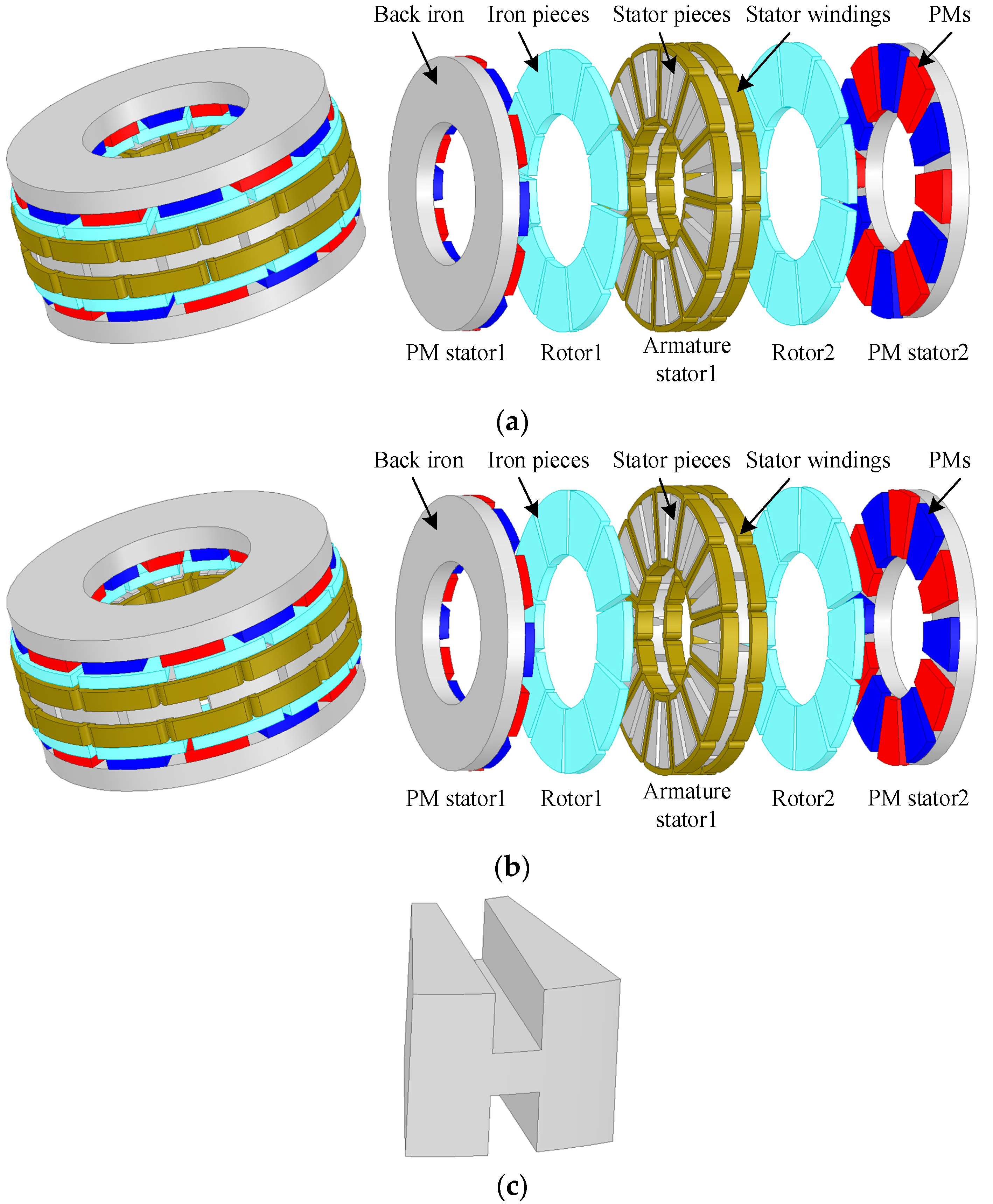
2.1. Proposed Machine Configurations

Figure 1 shows the proposed 3-phase AF-FMPM machine configurations, which all consist of dual identical outer surface-mounted PM stators, one inner armature stator and two identical sandwiched rotors. The dual identical outer surface-mounted PM stators facing each other are arranged to be either N and S-pole (NS), shown in Figure 1a or N and N-pole (NN), shown in Figure 1b. The inner armature stator is formed by separated iron pieces with H type as shown in Figure 1c, and the concentrated windings are embedded into the slots of adjacent H iron pieces radially. Based on the inner armature stator, the proposed machines can be capable of operating as a dual 3-phase machine when the windings are properly connected. The two identical sandwiched rotors sandwiching respectively between outer surface-mounted PM stator and inner armature stator, are composed of several evenly distributed iron pieces only.
The AF-FMPM machines proposed exhibit the following advantages:
(1)
The static PM stator can prevent the PM from falling off when the machine runs, also the structure is easier to cool.
(2)
The prominent salient teeth of the PM stator and the salient rotor presents abundant field harmonics in the air gap of the proposed AF-FMPM machines, which makes the machine output to present stable electromagnetic torque.
(3)
Owing to the disc structure of multi-stator and multi-rotor, the torque density of the proposed machine can be significantly increased, making it suitable for direct drive applications.
(4)
Concentrated windings of the proposed machine can reduce the usage of copper and depress the copper loss, resulting in high machine efficiency.
(5)
The rotor is simple and robust.
(6)
Symmetrical machine structure is also easy to manufacture.

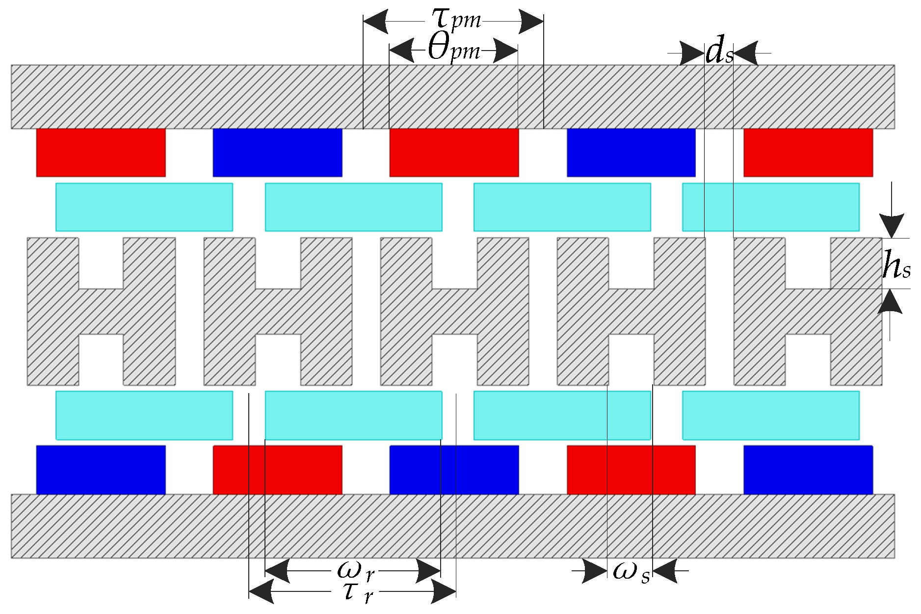
2.2. Operation Principle

For the proposed 3-phase AF-FMPM machines with Ns stator slots and Nr rotor poles, in which the coils wound all the poles, the pole-pair number of PM filed in the proposed machine is obviously obtained by Equation (1)
P PM = N s 2
where PPM is the pole-pair number of PM field.
Different from traditional rotor-PM machine, the PMs and armature windings of the proposed AF-FMPM machines are all located on different stators. Based on the flux-modulation effect, the relationship between pole-pair number of PM field, pole-pair number of armature field, and rotor poles in the proposed AF-FMPM machine is governed by Equation (2) [27].
P PM + P w = N r
where Pw is for the pole-pair number of armature field.
Due to the salient teeth of both inner armature stator and rotor, PM and armature winding fields can be modulated, and there will be abundant harmonic components in the air gap of the proposed machine. The harmonic pole-pair number and rotational speed corresponding to its harmonic component generated by PM and armature fields can be respectively expressed as the following equations:
{ P ( i , j ) PM = | i P PM + j N r | ω ( i , j ) PM = j N r i P PM + j N r ω r
{ P ( m , k ) w = | m P w + k N r | ω ( m , k ) w = m P w m P w + k N r ω w + k N r m P w + k N r ω r
where i = m = 1, 3, 5, …, j = k = 0, ±1, ±2, ±3, …, wr is the rotational speed of the rotor, ww is the synchronous speed related to the power supply.
Similar to the mechanism of the electromagnetic torque generation in conventional rotor-PM machines, in order to output stable electromagnetic torque, some specific field harmonic components generated by PM and armature fields should satisfy the following equations:
{ P ( i , j ) PM = P ( m , k ) w ω ( i , j ) PM = ω ( m , k ) w

3. Influence of Critical Parameters on Machine Performance

With the aim of obtaining the maximum torque transmission capability, the proposed machine is globally optimized by utilizing ANSYS Maxwell 3-D FEA. During the study process, the constant parameters and dimensions of the proposed machine are obtained and provided in Table 1.
To analyze the influence of structure parameters on machine performance, some dimensional definitions of the proposed machine are indicated in Figure 2, and the variable parameters are listed in Table 2. The main dimensions of the proposed machine including the magnet arc angle, rotor pole angle, stator slot width, stator slot depth, will all be analyzed by utilizing 3-D FEA, individually. It is worth noting that during the process of researching optimal value of each individual parameter for maximizing the machine average torque, other parameters of the proposed machine should be fixed.
During this study, the NdFe35 with remanence of 1.23 T is used as PM material in PM stator. The iron core of armature stator and rotor, including the back iron of PM stator is made of steel_1010. Moreover, copper is considered as the material of winding on the armature stator.

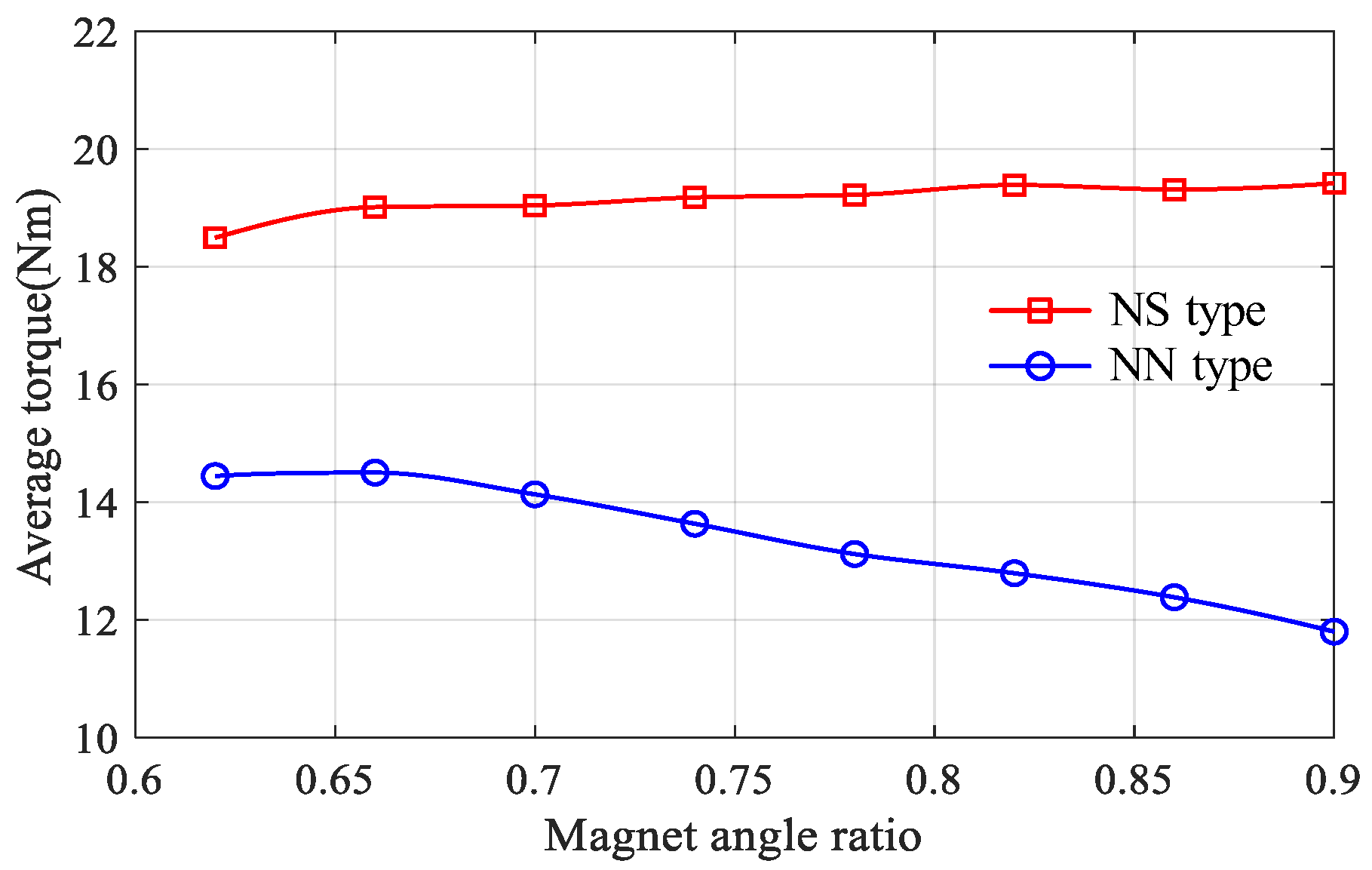
3.1. Influence of Magnet Angle

The influence of different magnet angle ratios on average torque of the proposed machine is illustrated in Figure 3, in which the average torque of the AF-FMPM machine (NS) slightly increases with the increase of magnet angle ratio, while that of the AF-FMPM machine (NN) decreases with the increase of the magnet angle ratio. It can be found that the maximum output torque of AF-FMPM machine (NS) can be obtained when Spm_ratio is approximately 0.9, and for AF-FMPM machine (NN), the optimal value of Spm_ratio is 0.66. Moreover, the average torque of the AF-FMPM machine (NS) is always higher compared to that of the AF-FMPM machine (NN) in the case of the same magnet angle ratio.

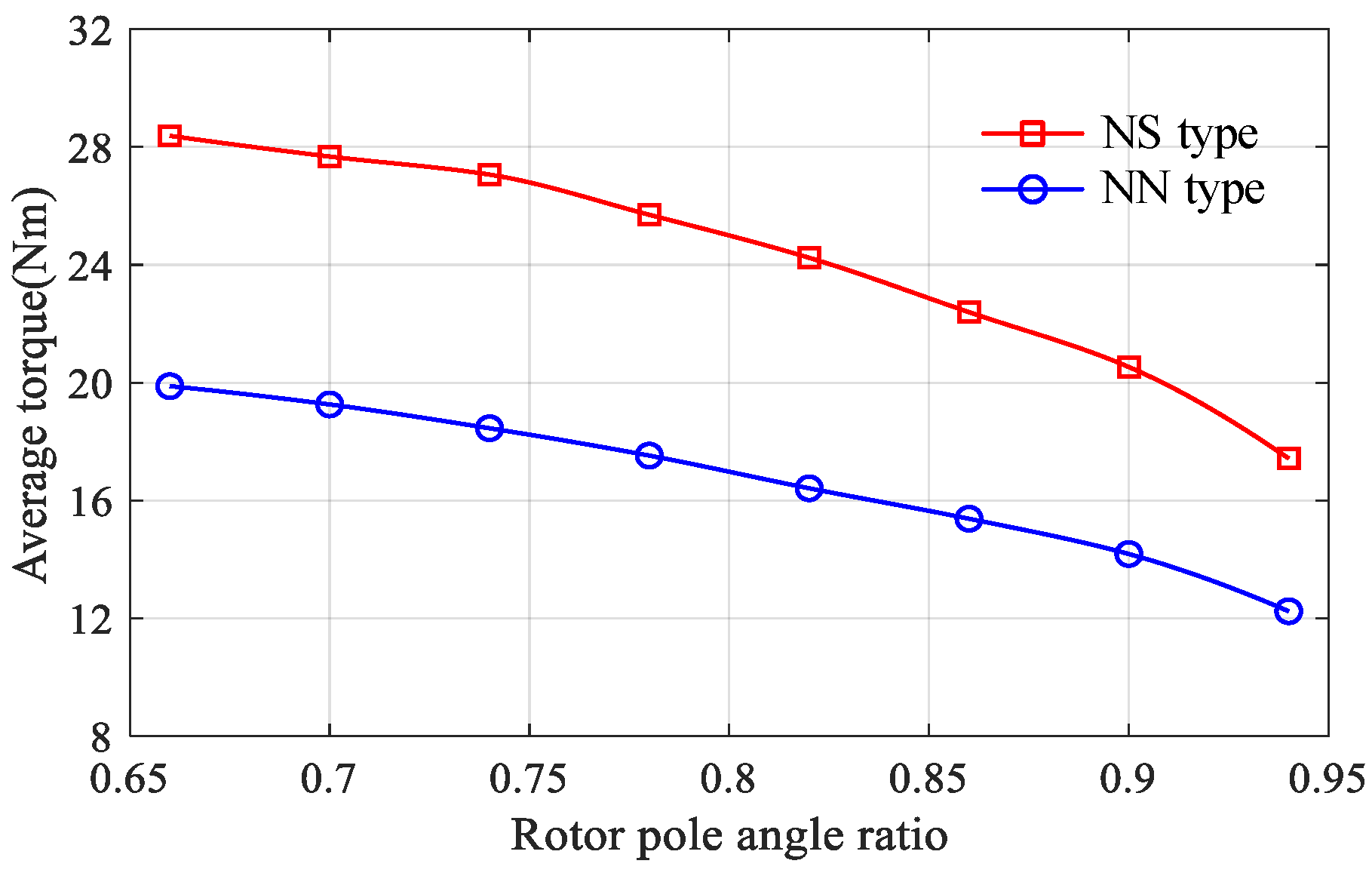
3.2. Influence of Rotor Pole Angle

Figure 4 shows a comparison of the influence of the rotor pole angle on the average torque. It is obvious that the average torque is sensitive to the rotor pole angle, i.e., the torque decreases with the increase of the rotor pole angle. However, the leakage flux passed only through one rotor tooth and the adjacent permanent magnet on PM stator changes in opposite direction. As a result, the main flux reduces significantly. It can be seen that both topologies can obtain the optimal average torque when the rotor angle ratio is designed at approximately 0.66. Obviously, AF-FMPM machine (NS) machine exhibits higher average torque than that of AF-FMPM machine (NN) machine as shown in horizontal axis. It is clear that the optimum average torque of the AF-FMPM machine (NS) is approximately 28.4 N·m, whereas that of the AF-FMPM machine (NN) is approximately 19.9 N·m.

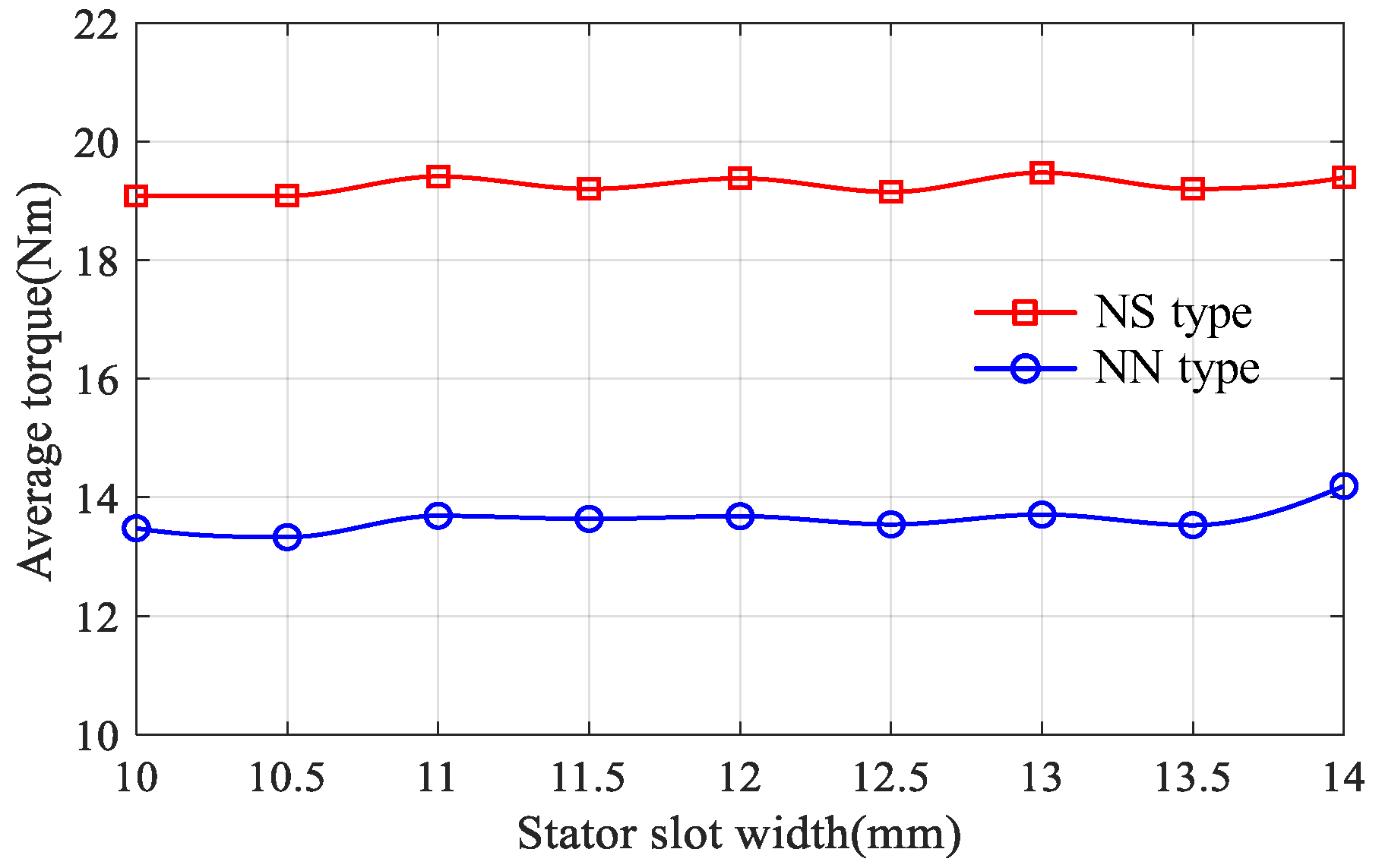
3.3. Influence of Slot Width

The relationship between average torque, the proposed AF-FMPM machines, and the slot width is shown in Figure 5, in which the slot width of 13 mm is approximately the optimal value for the AF-FMPM machine (NS). It can be found that the average torque of the AF-FMPM machine (NS) slightly fluctuates at about 19 N·m as the slot width changes from 10 mm to 14 mm. In this case, the slot width can affect the torque produced by the armature reaction and FM effect. Moreover, the variation of stator slot width has relatively no significant effect on the average torque of the AF-FMPM machine (NN). When the stator slot width is 14 mm, the average torque reaches its maximum.

3.4. Influence of Slot Depth

When the stator slot width is kept constant, the relationship between the average torque of the proposed AF-FMPM machines and the stator slot depth is shown in Figure 6. The variation of stator slot depth has relatively no significant effect on the average torque of the AF-FMPM machine (NS), and the maximum output torque of the AF-FMPM machine (NS) is obtained when the stator slot depth is approximately 15.25 mm. Since the stator yoke is used as the magnetic circuit path, the variation of stator slot depth has a greater effect on the average torque of the AF-FMPM machine (NN). As the slot depth increases, the magnetic flux flowing through the narrowed stator yoke decreases, resulting in a reduction in torque. For the proposed NN type machine, the optimal value is 14.5 mm for the maximum output torque.

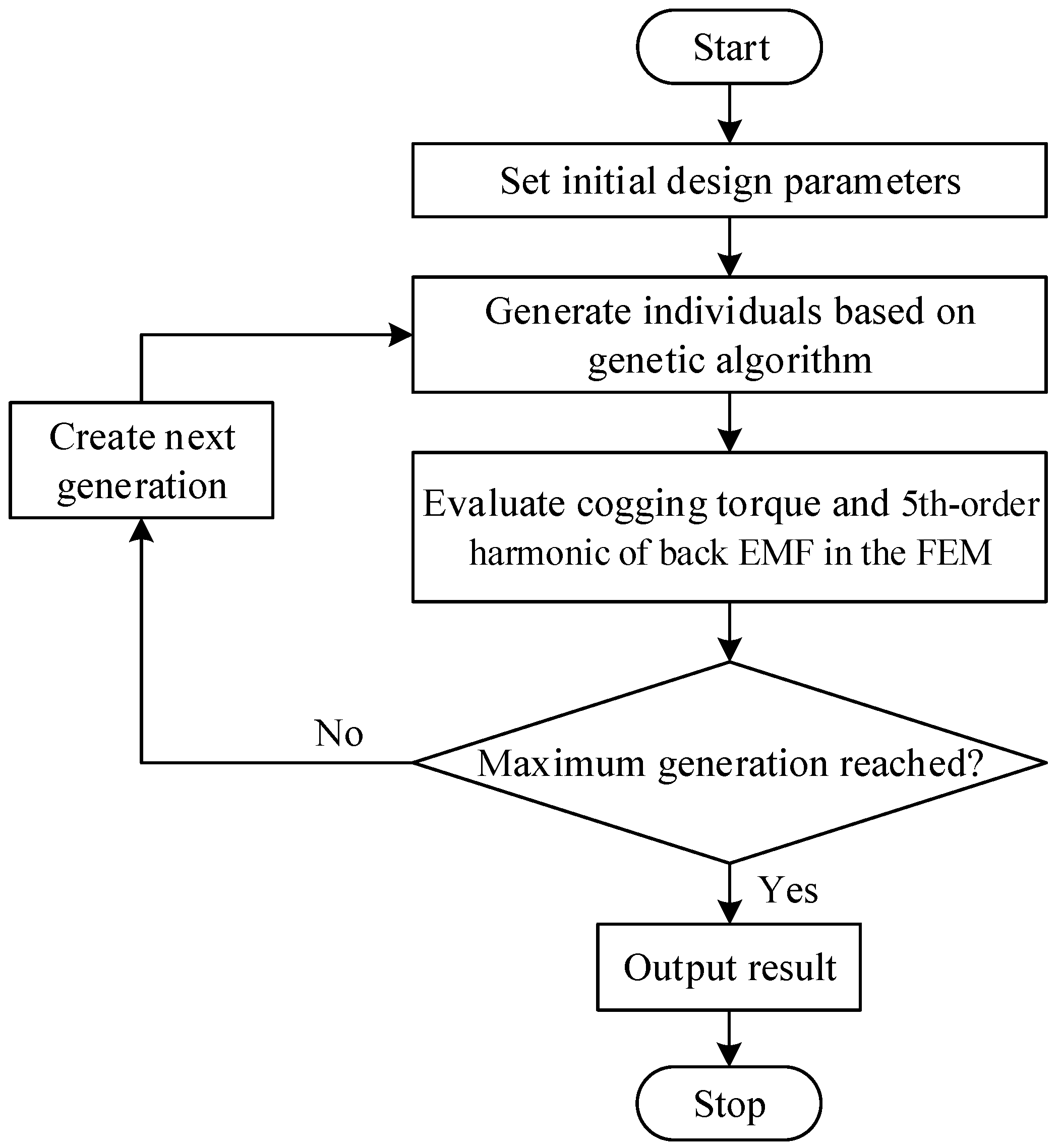
4. Design Optimization

Cogging torque is caused by the tangential component of the interaction force between PM and grooved stator core under the no-load condition. In other words, the interaction of the permeance harmonics and the MMF harmonics caused by PM resulted in unwanted torque pulsating, which makes the machine produce vibration and noise, especially at a low rotor speed. Therefore, the optimization of the AF-FMPM machine should be conducted with the consideration of reducing the cogging torque. In addition, the sinusoidal characteristic of open-circuit phase back EMF is also important to the machine performance. To quantitatively analyze the back EMF of the AF-FMPM machine, the phase back EMF of the AF-FMPM machine (NS) under no-load condition is selected for Fourier analysis. The no-load phase back EMF and the corresponding spectra of the proposed AF-FMPM machine (NS) are presented in Figure 7. It can be seen that the proportion of the high-order harmonics to the fundamental amplitude of the phase back EMF is relatively small, and the total harmonic distortion (THD) of the phase back EMF is 6.17% in the proposed AF-FMPM machine (NS). Moreover, there are many odd-order harmonic components in the phase back EMF, and the main component is the 5th-order harmonics.
Genetic algorithm (GA) is a popular metaheuristic algorithm and classified as an optimization algorithm. This algorithm is usually used to generate high-quality solutions for optimization problems and search issues. It works in a similar way to the evolutionary process observed in nature. Each generation consist of a population of individuals, each representing a point in search space and possible solution. On the basis of fitness function, the discriminators of the quality of solution are crossover and mutation in order to produce offspring of the next generation. Then the algorithm repeats the above procedure until the termination condition has been reached [28].
The design optimization is performed by a multi-objective genetic algorithm (GA) with the constraints of the fixed overall sizing (the stator outer diameter and the stack length), and the optimization flowchart is shown in Figure 8. Optimization goal is to simultaneously minimize the 5th-order harmonic of phase back EMF and the cogging torque. Since the key parameters, e.g., magnet angle ratio, rotor pole angle ratio, stator slot width, and stator slot depth influence both cogging torque and phase back EMF, their corresponding scopes are listed in Table 3.
All the design variables are globally optimized with multi-objective GA, which can be employed to achieve the optimum design without considering the optimization sequence. Meanwhile, the constraint ranges are assigned to avoid the conflicts and errors during the geometric modeling process. The parameters of algorithm are set as:
(1)
The crossover probability and mutation probability are 0.5 and 0.2, respectively.
(2)
The whole optimization process uses 20 individuals for each generation and 15 generations in total to find the optimal machine.
After the multi-objective GA optimization, the Pareto front of the optimization along with the performances of the initial machine is shown in Figure 9. Taking the trade-off between cogging torque and the 5th-order harmonic of phase back EMF, the back point in Figure 9 is chosen as the final optimization result compared with all the optimal solutions.
Compared to the initial designed machine, the results show a reduction of the peak-to-peak value of the cogging torque from 7.59 to 3.88 N·m for the optimized designed machine, as shown in Figure 10. Figure 11 suggests that the optimized machine shows 44.7% lower torque ripple and only 3% lower average torque than the initial machine.
Figure 12 shows that the THD of phase back EMF is 6.99% in the initial designed machine and only 4.9% in the optimized designed machine. The optimized, compared with the initial machine shows a slight reduction of the fundamental harmonic EMF from 64.8 V to 62.3 V. Table 4 summarizes the design variables of the final machine as well as the variables of the initial machine. It is clear that the pole arc of rotor, PM, and armature stator structure play a key role in the cogging torque minimization and sinusoidal phase back EMF waveform.

5. Electromagnetic Performance Analysis

With the aid of 3D-FEA, both the 3-phase AF-FMPM machine (NS) and the 3-phase AF-FMPM machine (NN) are analyzed and compared. By considering the no-load condition, in which the winding current is zero, and on-load condition, in which the winding is applied by specific current, a performance (i.e., flux-linkage, phase back EMF, cogging torque and average torque) comparison between the proposed NS type machine and NN type machine is performed.

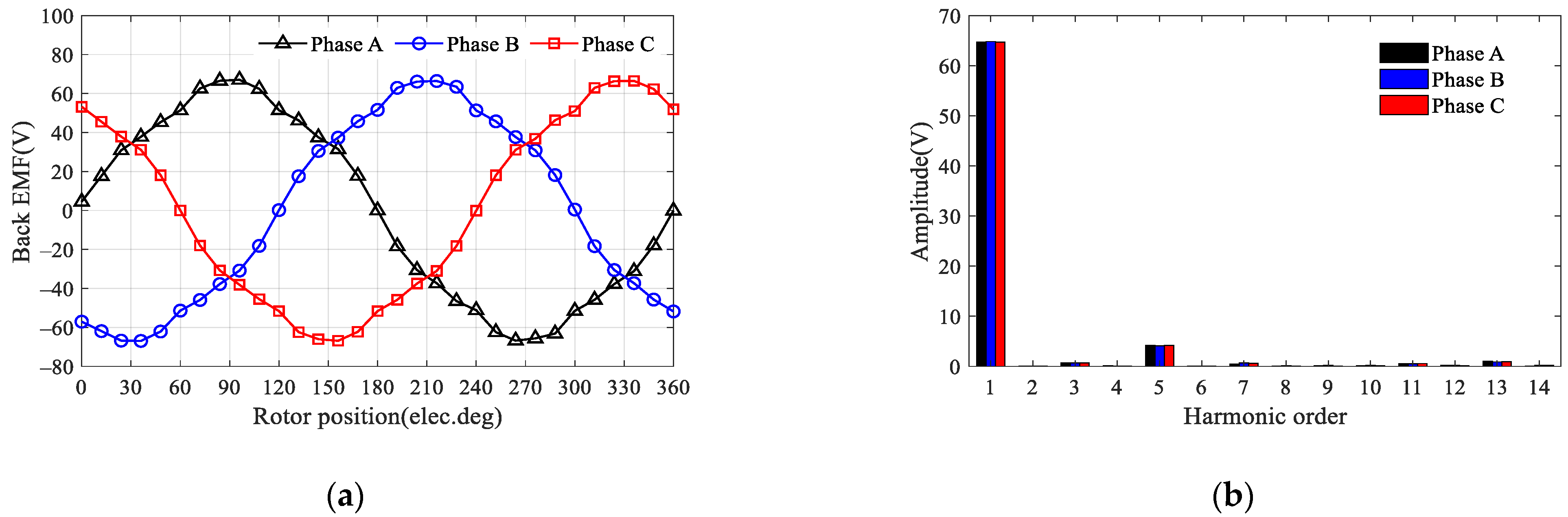
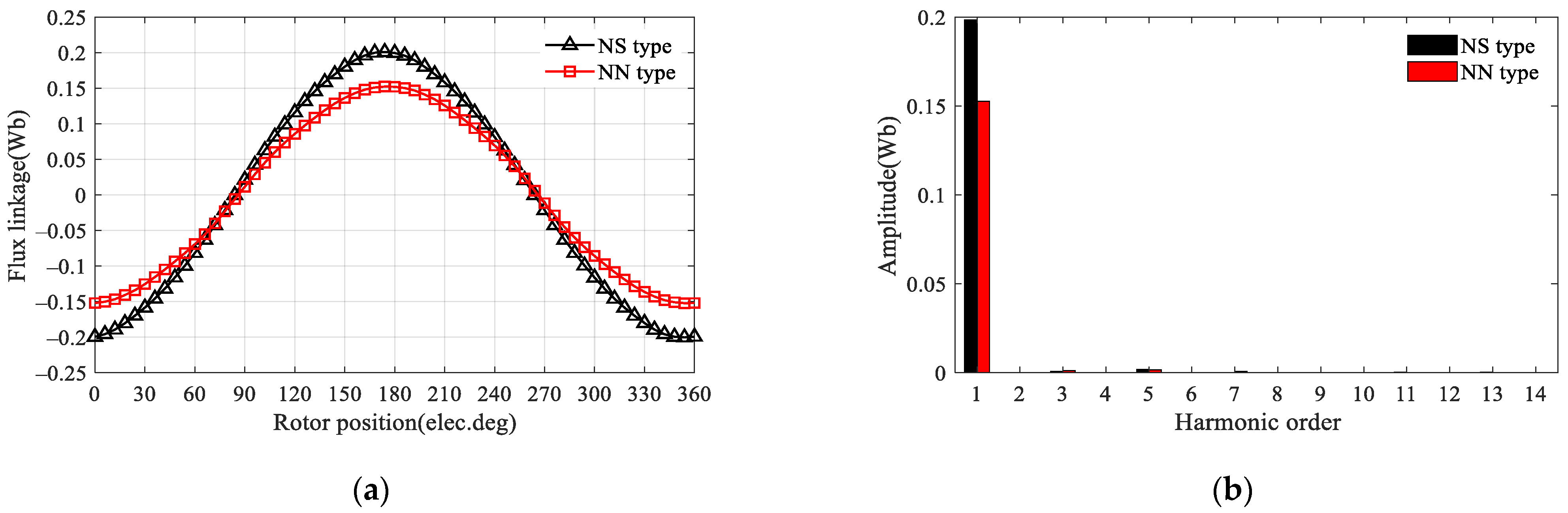
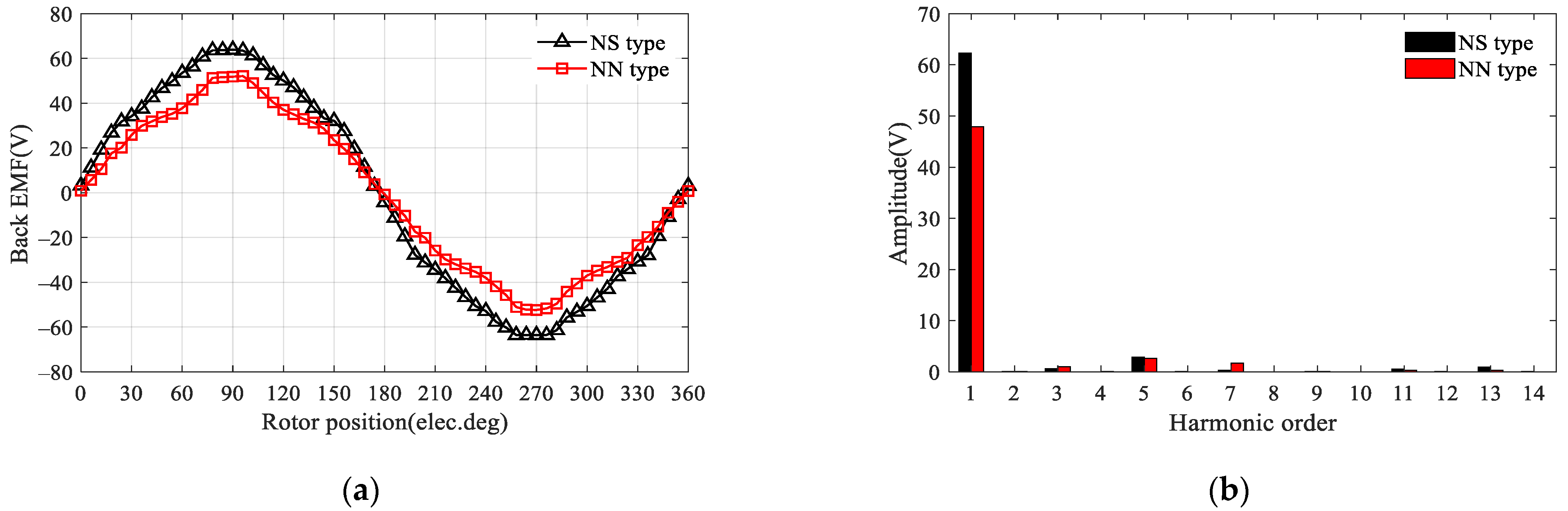
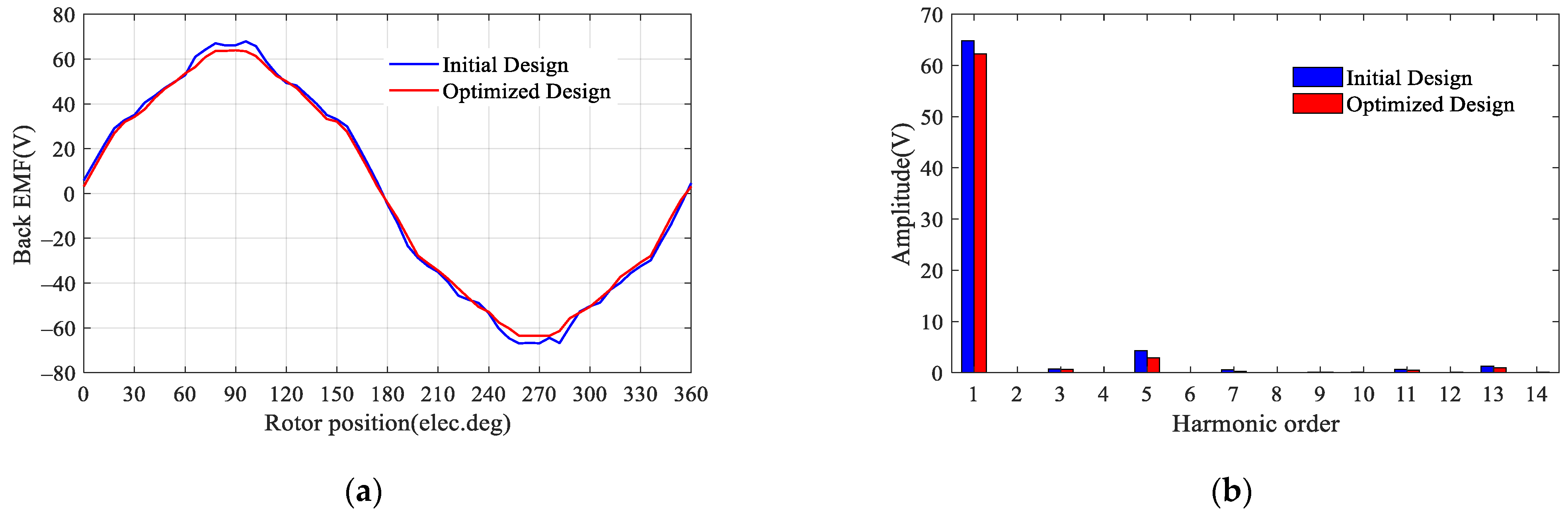
5.1. Open-Circuit Performance

A comparison of no-load results of the proposed AF-FMPM machine (NS) and AF-FMPM machine (NN) is first obtained. The open-circuit phase flux-linkage waveforms and harmonic spectra of the two machines are described in Figure 13. It can be seen that all the phase flux-linkages are both highly symmetrical and sinusoidal. Moreover, the AF-FMPM machine (NS) exhibits higher flux-linkage amplitude than that of the AF-FMPM machine (NN) when the winding current is 0 A. It is clear that the phase flux-linkage of the AF-FMPM machine (NS) has an amplitude of proximately 0.2 Wb, while the AF-FMPM machine (NN) only has an amplitude of 0.15 Wb due to the severe flux leakage.
In addition, the open-circuit phase back EMFs of the two proposed machines at 300 rpm and the corresponding harmonics are also compared and plotted in Figure 14. The amplitudes are about 64 V and 52 V in the AF-FMPM machine (NS) and AF-FMPM machine (NN), respectively. There are many odd-order harmonic components in the back EMF, and the main components are the 3rd-order, 5th-order, and 7th-order harmonics. Compared to the AF-FMPM machine (NS), the phase back EMF of the AF-FMPM machine (NN) includes higher odd order harmonics, such as 3rd and 7th, which make the phase back EMF non-sinusoidal. It can be calculated that the THDs are 4.9% and 6.79% in the AF-FMPM machine (NS) and AF-FMPM machine (NN), respectively. It also can be noticed that the THD of AF-FMPM machine (NS) is lower, which indicates smaller torque ripple in the AF-FMPM machine (NS).
The cogging torque of the AF-FMPM machine (NS) and AF-FMPM machine (NN) without the excitation current is illustrated in Figure 15. Obviously, the peak-to-peak value of the cogging torque is 4.37 N·m, obtained in the AF-FMPM machine (NN), while that of the AF-FMPM machine (NS) machine is only 3.88 N·m.

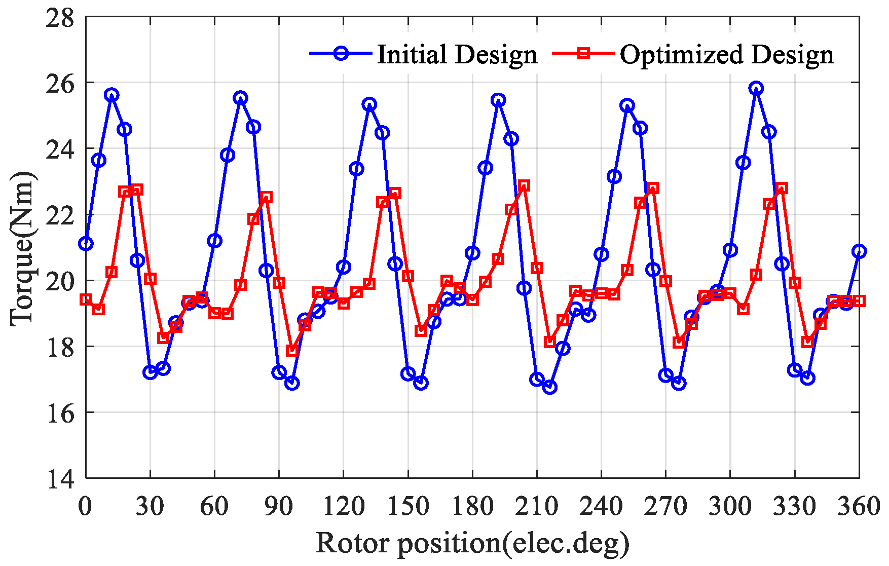
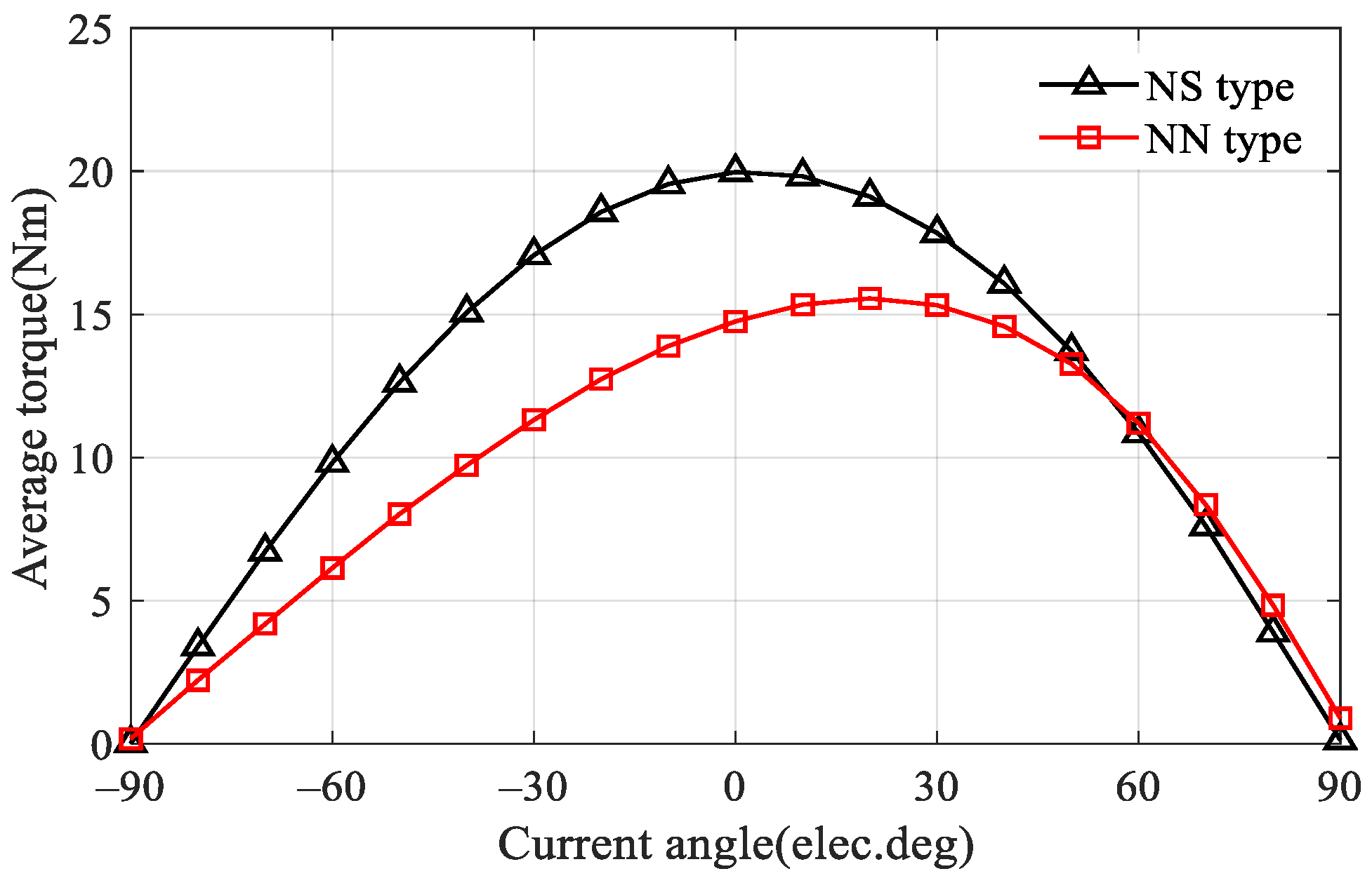
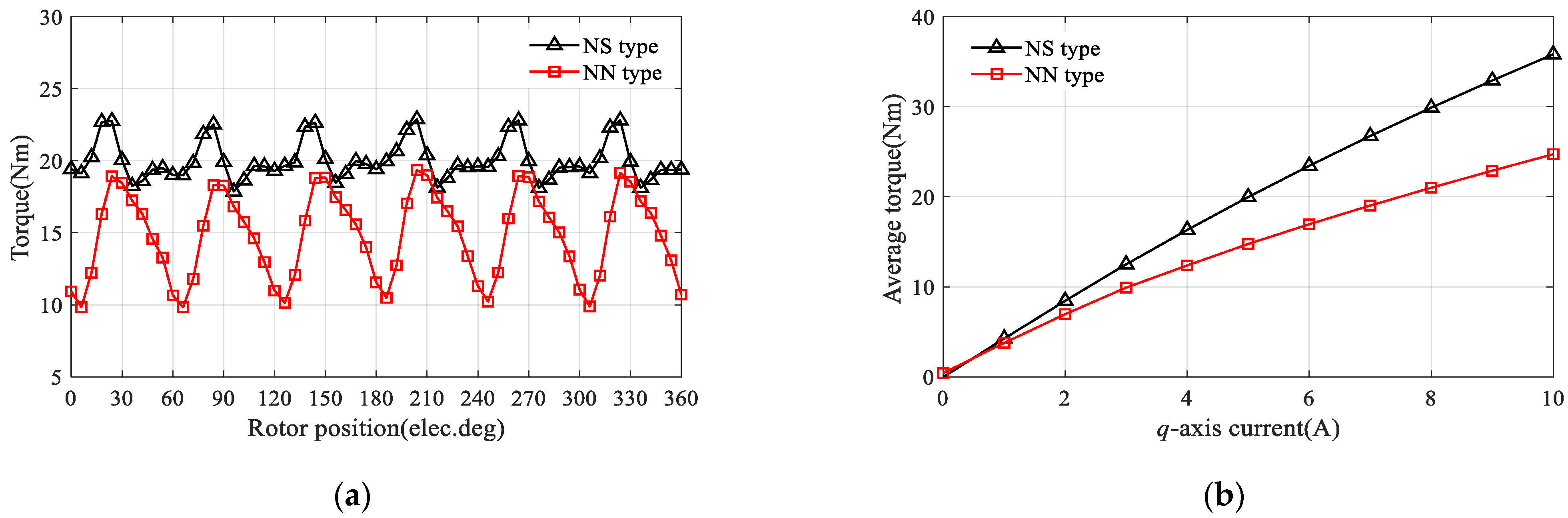
5.2. On-Load Torque Characteristics

To further illustrate the optimal current angle, the waveforms of average torque versus the current angle at rated current for both AF-FMPM machines are shown in Figure 16.
It is obvious that the average torque produced by armature reaction can be controlled by the current angle. In this case, the optimal current angle of AF-FMPM machine (NS) is near 0°, which means that the reluctance torque of AF-FMPM machine (NS) is negligible since the d- and q-axis inductances are almost equal. Thus, the Id = 0 control is fit for the AF-FMPM machine (NS). It can be observed that the AF-FMPM machine (NN) can reach the maximum values at approximately 20 electrical degrees, which means that the AF-FMPM machine (NN) has a greater salient ratio and reluctance torque.
In addition, the steady-state torque of AF-FMPM machines under both rated current (Irms = 5 A, “rms” denotes root-mean-square value) and zero d-axis current control is shown in Figure 17a. It demonstrates that the AF-FMPM machine (NS) provides 25.7% higher average torque, together with 39.3% lower torque ripple than those of the AF-FMPM machine (NN). The calculated torque density of the AF-FMPM machine (NS) and AF-FMPM machine (NN) are about 9.58 kNm/m3 and 7.12 kNm/m3, respectively. Figure 17b shows the average torque versus current characteristics of the two machines, in which the proposed AF-FMPM machine (NS) holds the torque advantages over all range. It can be seen that the average torque is linear with the armature current when the machine speed was rated and the d-axis current was zero. Consequently, the armature current of AF-FMPM machine can meet the requirements of output torque under light load.

6. Conclusions

In this paper, an in-depth investigation of the machine configurations with different PM stator position and its flux-modulation principle of the novel AF-FMPM machine is carried out. From the theoretical analysis and the results globally optimized by utilizing ANSYS Maxwell 3-D FEA, the detailed findings can be summarized as follows.
(1)
The prominent salient teeth of the PM stator and the salient rotor presents abundant field harmonics in the air gap of the proposed AF-FMPM machine, which makes the machine output to present stable electromagnetic torque.
(2)
The magnet arc angle, rotor pole angle, stator slot width, stator slot depth have significant influence on the proposed machine either the NN type or the NS type.
(3)
There are many odd-order harmonic components in the back EMF of the proposed machine, and the THDs of AF-FMPM machine (NS) and AF-FMPM machine (NN) are 4.9% and 6.79%, respectively.
(4)
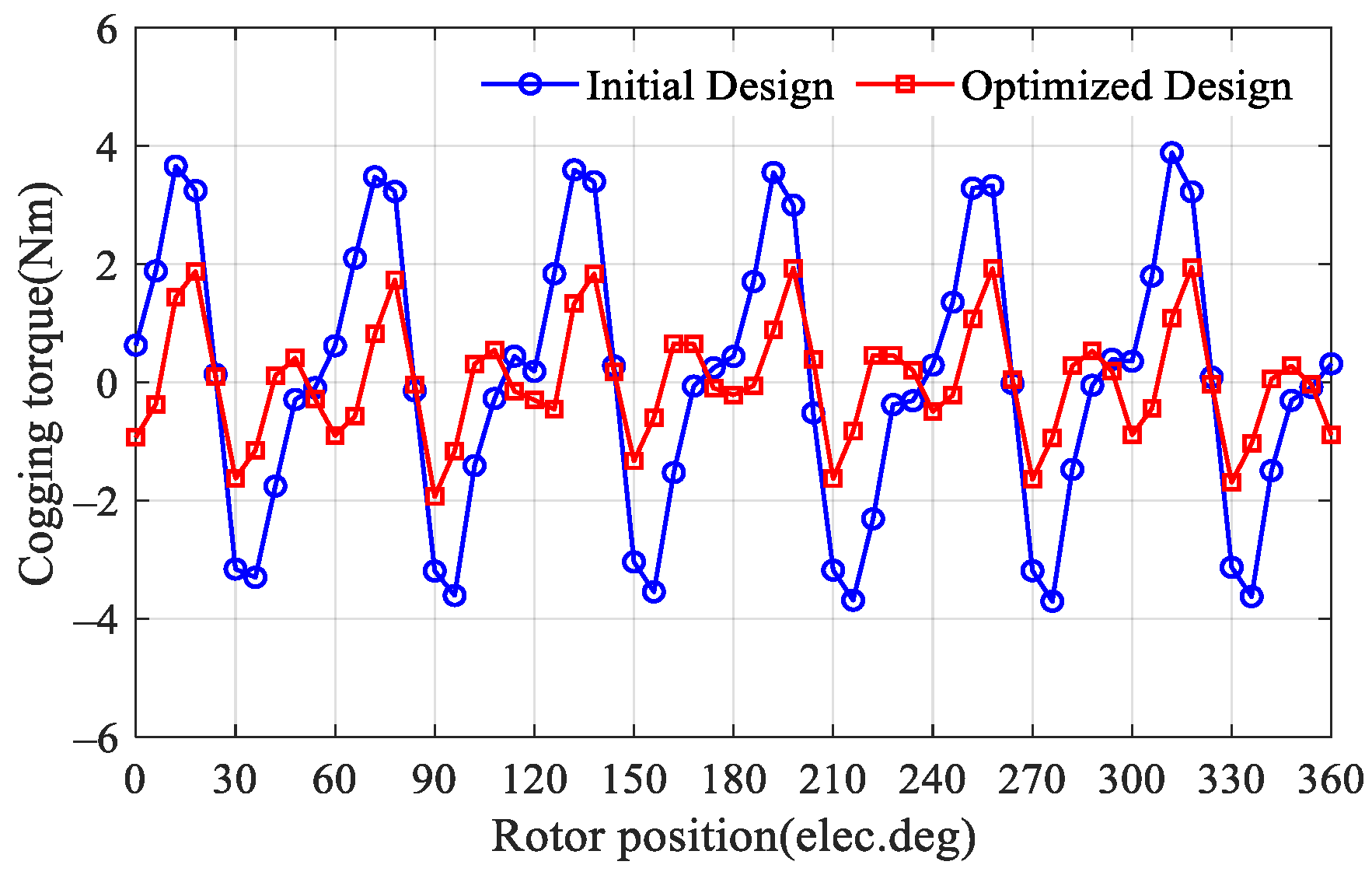
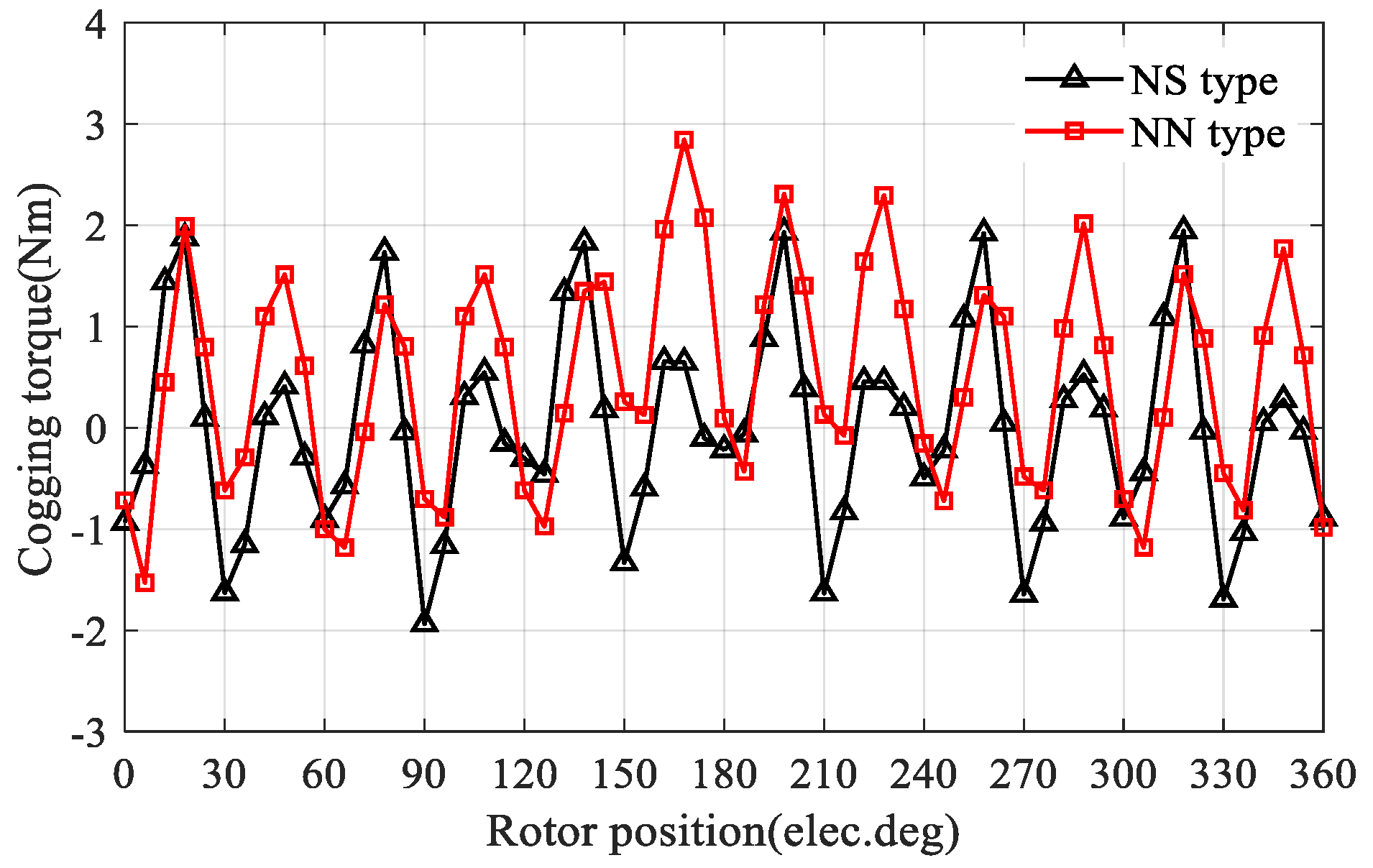
The peak-to-peak value of the cogging torque is 4.37 N·m, obtained in the AF-FMPM machine (NN), while that of the AF-FMPM machine (NS) is only 3.88 N·m.
(5)
The AF-FMPM machine (NS) shows non-salient characteristics, while the AF-FMPM machine (NN) is a salient machine.
(6)
The AF-FMPM machine (NS) was analyzed and the results indicated that it can obtain a high torque density of 9.58 kNm/m3, and a torque density of approximately 7.12 kNm/m3 was achieved by the AF-FMPM (NN) machine.
Benefiting from the above analysis, the proposed AF-FMPM machine with appropriate stator and rotor size and proper stator rotor slot/pole combination can be selected for direct drive application such as wind power generation, HEVs, and railway traction.

Author Contributions

Conceptualization, J.L. and G.Y.; methodology, G.Y.; software, J.L.; validation, J.L., G.Y. and F.R.; formal analysis, G.Y.; investigation, G.Y.; resources, G.Y.; data curation, G.Y.; writing—original draft preparation, J.L. and G.Y.; writing—review and editing, J.L. and G.Y.; visualization, J.L.; supervision, G.Y.; project administration, G.Y.; funding acquisition, G.Y. All authors have read and agreed to the published version of the manuscript.

Funding

This research was funded by China NCFC under Grant 52107039, natural Science Foundation of Fujian, China under Grant 2021J05133 and the Nature Science Basic Research Plan in Shaanxi Province of China under Grant 2020JM-458.

Institutional Review Board Statement

Not applicable.

Informed Consent Statement

Not applicable.

Data Availability Statement

Not applicable.

Acknowledgments

We would like to thank Jilong Zhao in Xi’an University of Technology for helping guide the design of this new machine, and for providing suggestions and help during the revision of this paper. We also thank the Nature Science Basic Research Plan in Shaanxi Province of China under Grant 2020JM-458 for their support of this work.

Conflicts of Interest

The authors declare no conflict of interest.

References

  1. Gardner, M.; Toliyat, H. Analysis of high gear ratio capabilities for single-stage, series multistage, and compound differential coaxial magnetic gears. IEEE Trans. Energy Convers. 2019, 34, 665–672. [Google Scholar] [CrossRef]
  2. Shuai, M.; Shuai, M.; Guang, J.; Xiang, Y. Research on dynamic load-sharing characteristics of two-stage asymmetric star gear system. IEEE Access 2019, 7, 126799–126811. [Google Scholar] [CrossRef]
  3. Prieto, M.; Millán, D. Chromatic monitoring of gear mechanical degradation based on acoustic emission. IEEE Trans. Ind. Electron. 2017, 64, 8707–8717. [Google Scholar] [CrossRef] [Green Version]
  4. Rasmussen, P.; Andersen, T.; Jorgensen, F.; Nielsen, O. Development of a high-performance magnetic gear. IEEE Trans. Ind. Appl. 2005, 41, 764–770. [Google Scholar] [CrossRef]
  5. Zhu, X.; Lee, T.; Chan, C.; Xu, L.; Zhao, W. Overview of flux-modulation machines based on flux-modulation principle: Topology, theory, and development prospects. IEEE Trans. Trans. Electrif. 2020, 6, 612–624. [Google Scholar] [CrossRef]
  6. Wang, Y.; Niu, S.; Fu, W. A novel dual-rotor bidirectional flux-modulation PM generator for stand-alone DC power supply. IEEE Trans. Ind. Electron. 2019, 66, 818–828. [Google Scholar] [CrossRef]
  7. Zhou, Y.; Qu, R.; Gao, Y.; Shi, C.; Wang, C. Modeling and analyzing a novel dual-flux-modulation consequent-pole linear permanent-magnet machine. IEEE Trans. Magn. 2019, 55, 8203906. [Google Scholar] [CrossRef]
  8. Liang, Z.; Gao, Y.; Li, D.; Qu, R. Design of a novel dual flux modulation machine with consequent-pole spoke-array permanent magnets in both stator and rotor. CES Trans. Electric. Mach. 2018, 2, 73–81. [Google Scholar] [CrossRef]
  9. Sun, L.; Zhang, Z.; Yu, L.; Gu, X. Development and analysis of a new hybrid excitation brushless DC generator with flux modulation effect. IEEE Trans. Ind. Electron. 2019, 66, 4189–4198. [Google Scholar] [CrossRef]
  10. Zhao, W.; Zhu, J.; Ji, J.; Zhu, X. Improvement of power factor in a double-side linear flux-modulation permanent-magnet motor for long stroke applications. IEEE Trans. Ind. Electron. 2018, 66, 3391–3400. [Google Scholar] [CrossRef]
  11. Jiang, M.; Zhu, X.; Xiang, Z.; Quan, L.; Que, H.; Yu, B. Suppression of torque ripple of a flux-switching permanent magnet motor in perspective of flux-modulation principle. IEEE Trans. Trans. Elect. 2022, 8, 1116–1127. [Google Scholar] [CrossRef]
  12. Yu, Z.; Gan, C.; Chen, Y.; Qu, R. DC-biased sinusoidal current excited switched reluctance motor drives based on flux modulation principle. IEEE Trans. Power Electron. 2020, 35, 10614–10628. [Google Scholar] [CrossRef]
  13. Zhu, X.; Zhao, W.; Xu, L. Distribution design of modulator for split-pole flux-modulation permanent-magnet machine. IEEE Trans. Energy Convers. 2021, 36, 1614–1624. [Google Scholar] [CrossRef]
  14. Cheng, B.; Pan, G.; Mao, Z. Analytical calculation and optimization of the segmented-stator dual-rotor axial flux permanent magnet motors. IEEE Trans. Magn. 2020, 56, 8101709. [Google Scholar]
  15. Zhang, W.; Liang, X.; Lin, M. Analysis and comparison of axial field flux-switching permanent magnet machines with three different stator cores. IEEE Trans. Appl. Supercond. 2016, 26, 0607806. [Google Scholar] [CrossRef]
  16. Hao, L.; Lin, M.; Xu, D.; Fu, X.; Zhang, W. Static characteristics of a novel axial field flux-switching permanent magnet motor with three stator structures. IEEE Trans. Magn. 2014, 50, 4002604. [Google Scholar] [CrossRef]
  17. Mezani, S.; Atallah, K.; Howe, D. A high-performance axial-field magnetic gear. J. Appl. Phys. 2006, 99, 08R303-1–08R303-3. [Google Scholar] [CrossRef]
  18. Zaytoon, H.; Abdel-Khalik, A.; Massoud, A.; Ahmed, S. An axial magnetic gearbox with an electric power output port. In Proceedings of the 2014 IEEE Applied Power Electronics Conference and Exposition—APEC, Fort Worth, TX, USA, 16–20 March 2014. [Google Scholar]
  19. Khatab, M.; Zhu, Z.; Li, H.; Liu, Y. Comparative study of novel axial flux magnetically geared and conventional axial flux permanent magnet machines. CES Trans. Electric. Mach. 2018, 2, 392–398. [Google Scholar] [CrossRef]
  20. Zhu, Z.; Khatab, M.; Li, H.; Liu, Y. A novel axial flux magnetically geared machine for power split application. IEEE Trans. Ind. Appl. 2018, 54, 5954–5966. [Google Scholar]
  21. Tong, C.; Song, Z.; Zheng, P.; Bai, J.; Zhao, Q. Research on electromagnetic performance of an axial magnetic-field-modulated brushless double-rotor machine for hybrid electric vehicles. In Proceedings of the International Conference on Electrical Machines & Systems, Berlin, Germany, 2–5 September 2014. [Google Scholar]
  22. Lai, J.; Jian, L.; Qu, R.; Zhang, R.; Li, D. A novel axial flux magnetic-field-modulated dual-mechanical-port dual-electrical-port machine for hybrid electric vehicle. In Proceedings of the 2016 IEEE Vehicle Power and Propulsion Conference (VPPC), Hangzhou, China, 17–20 October 2016. [Google Scholar]
  23. Zhang, R.; Li, J.; Qu, R.; Li, D. A novel triple-rotor axial-flux vernier permanent magnet machine. IEEE Trans. Appl. Supercond. 2016, 26, 0610405. [Google Scholar] [CrossRef]
  24. Zhang, R.; Li, J.; Qu, R.; Li, D. Analysis and design of triple-rotor axial-flux spoke-array vernier permanent magnet machines. IEEE Trans. Ind. Appl. 2018, 54, 244–253. [Google Scholar]
  25. Rallabandi, V.; Han, P.; Kesgin, M.; Taran, N.; Ionel, D. Axial-field Vernier-type Flux Modulation Machines for Low-speed Direct-drive Applications. In Proceedings of the 2019 IEEE Energy Conversion Congress and Exposition (ECCE), Baltimore, MD, USA, 29 September–3 October 2019. [Google Scholar]
  26. Wang, S.; Lin, K.; Lin, M.; Kong, Y.; Xu, D.; Li, N.; Wang, P. Comparative study of E- and U-core modular dual-stator axial-field flux-switching permanent magnet motors with different stator/rotor-pole combinations based on flux modulation principle. IEEE Access 2021, 9, 78635–78647. [Google Scholar]
  27. Shi, Y.; Jian, L.; Wei, J.; Shao, Z.; Li, W.; Chan, C. A new perspective on the operating principle of flux-switching permanent-magnet machines. IEEE Trans. Trans. Electron. 2016, 63, 1425–1437. [Google Scholar]
  28. Le, W.; Lin, M.; Jia, L.; Ai, J.; Fu, X.; Chen, Z. Multi-Objective Optimization of an Air-Cored Axial Flux Permanent Magnet Synchronous Machine with Segmented PMs based on Support Vector Machine and Genetic Algorithm. In Proceedings of the 2019 22nd International Conference on Electrical Machines and Systems (ICEMS 2019), Harbin, China, 11–14 August 2019. [Google Scholar]
Figure 1. Proposed machine configurations: (a) NS type configuration; (b) NN type configuration; (c) H iron piece.
Machines 10 00495 g001
Figure 2. Dimensional definitions of the proposed machine.
Machines 10 00495 g002
Figure 3. Influence of magnet angle on average torque.
Machines 10 00495 g003
Figure 4. Influence of rotor pole angle on average torque.
Machines 10 00495 g004
Figure 5. Influence of stator slot width on average torque.
Machines 10 00495 g005
Figure 6. Influence of stator slot depth on average torque.
Machines 10 00495 g006
Figure 7. Open-circuit phase back EMF characteristic of the proposed AF-FMPM machine (NS). (a) Waveform; (b) harmonic spectra.
Machines 10 00495 g007
Figure 8. Flowchart of the optimization process.
Machines 10 00495 g008
Figure 9. Pareto front of GA optimization.
Machines 10 00495 g009
Figure 10. Cogging torque comparisons of the initial and optimized machines.
Machines 10 00495 g010
Figure 11. Electromagnetic torque comparisons of the initial and optimized machines.
Machines 10 00495 g011
Figure 12. Open-circuit phase back EMF comparisons. (a) Waveform; (b) harmonic spectra.
Machines 10 00495 g012
Figure 13. Comparison of no-load phase flux linkage waveforms at rated speeds. (a) Waveform; (b) harmonic spectra.
Machines 10 00495 g013
Figure 14. Comparison of no-load phase back EMF waveforms at rated speeds. (a) Waveform; (b) harmonic spectra.
Machines 10 00495 g014
Figure 15. Comparison of cogging torques of AF-FMPM machine topologies.
Machines 10 00495 g015
Figure 16. Variation of average torque with current angle in AF-FMPM machines.
Machines 10 00495 g016
Figure 17. Comparison of electromagnetic torques of AF-FMPM machine topologies. (a) Torque at rated speed and rated current; (b) average torque versus currents.
Machines 10 00495 g017
Table 1. Constant parameters of the proposed machine.
ParameterAF-FMPM Machine (NS)AF-FMPM Machine (NN)
Rated speed (rpm)300300
Pole-pair number of rotor1010
Pole-pair number of armature field44
Pole-pair number of PM field66
Outer diameter (mm)210210
Inter diameter (mm)110110
Axial length (mm)104104
Air-gap length (mm)0.50.5
Table 2. Variable parameters of the proposed machines.
ParameterSymbolDefinition
Magnet angle ratiospm_ratio θ pm τ pm
Rotor pole angle ratiorratio ω r τ r
Stator slot widthsw ω s
Stator slot depthsdhs
Stator tooth distancestds
Table 3. Range of design parameters of the AF-FMPM machine.
ParameterRange
Magnet angle ratio0.6~0.9
Rotor pole angle ratio0.7~0.95
Stator slot width (mm)10~14
Stator slot depth (mm)14.5~16
Stator tooth distance (mm)6~8
Table 4. Comparations of variable parameters of the proposed machines.
ParameterSymbolInitial ValueOptimized Value
Magnet angle ratiospm_ratio0.80.759
Rotor pole angle ratior_ratio0.90.915
Stator slot width (mm)sw1211.33
Stator slot depth (mm)sd1514.8
Stator tooth distance (mm)st76.35
Publisher’s Note: MDPI stays neutral with regard to jurisdictional claims in published maps and institutional affiliations.

