1. Introduction
Aramid fiber-reinforced plastic (AFRP) composites are composed of aramid fibers as reinforcement and epoxy resins as matrix material. In addition to the common advantages of composites, such as high specific strength, high impact resistance, fatigue resistance and excellent designable property, AFRP composites also have special properties, such as insulation, vibration damping, puncture resistance and so on [
1]. These advantages make them widely used in aerospace, rail transit, marine and military industries [
2,
3]. In the aerospace field, AFRP composites are often mixed with carbon fiber-reinforced plastic composites. They are used in aircraft engine shell, aircraft wing box, wall panel and skin, making the aircraft structure lighter, smaller and higher-performance.
After the molding of AFRP composites, in order to meet different application requirements, a lot of machining is needed, such as hole making, window opening, edge cutting and so on [
4]. Like other laminated composites, AFRP composites have the characteristics of low interlaminar shear and tensile strength, which is easy to produce delamination damages during machining [
5,
6]. In addition, in the cutting process, large cutting force, cutting heat and serious tool wear make AFRP composites prone to machining damages, such as burr, wire drawing, resin burn, matrix cracking, material flanging and bulge at the entrance and exit, etc. [
7,
8]. These damages seriously affect the dimensional accuracy, shape accuracy and assembly quality of the AFRP parts. Furthermore, damages significantly reduce the mechanical properties of composite components, especially their compressive strength and fatigue strength [
9]. Composite materials are very sensitive to damages. Under the service load, damages may expand due to stress concentration, resulting in the weakening of product performance and reliability [
10].
In order to improve the cutting quality of AFRP composites, scholars have carried out much theoretical and experimental research. Because of the low cost, the traditional milling process is the most widely used technology for cutting AFRP composites. Many scholars have studied the influence of milling process parameters, milling cutter geometric parameters, milling cutter materials and wear on the milling effect (such as milling force, milling quality, etc.) through milling experiments. The milling quality of AFRP composites can be improved to a certain extent by reasonably designing the helical angle of the milling cutter, optimizing milling process parameters and adopting low-temperature milling [
11,
12,
13]. However, due to the large diameter of the milling cutter, the material loss during edge milling is large, and the narrow slit cannot be milled. Non-traditional machining methods are also used to cut AFRP composites by many scholars, including laser cutting [
14,
15], high-pressure water jet cutting [
16,
17], ultrasonic assisted cutting [
18,
19], etc. The quality of AFRP was improved by incrementing the pressure and abrasive flow rate in abrasive water jet machining. The lowest
Ra values obtained were 4.135 μm for trimming, 5.962 μm for pocketing, and 4.696 μm for the hole-making operation [
20]. Although these methods can improve the cutting quality to a certain extent, there are also some problems, such as high equipment price, high processing cost and low efficiency.
There are two main reasons why it is difficult to obtain regular surfaces when milling AFRP composites. One reason is that the edge radius of the milling cutter is much larger than the diameter of the aramid fiber which is about 10 μm. Aramid fiber has the characteristics of high tensile strength (3.0–3.8 GPa) and strong toughness. The elongation at break of Kevlar fiber is 2.4%–4.4%. It is difficult to be cut off neatly by the cutter along the edge of the workpiece, especially by the blunt milling cutter with large cutting edge radius. After cutting, there will always be a layer of floc filaments remaining at the edge of the material, that is, the burr phenomenon. In other cases, the aramid fibers are pulled out of the matrix in bundles rather than cut off by the cutter, resulting in wire drawing and resin matrix cracking. The second reason is that the cutting speed of milling is usually low. For the aramid fiber with high toughness, increasing the cutting speed can reduce its deformation before fracture, so as to obtain good machining quality [
21].
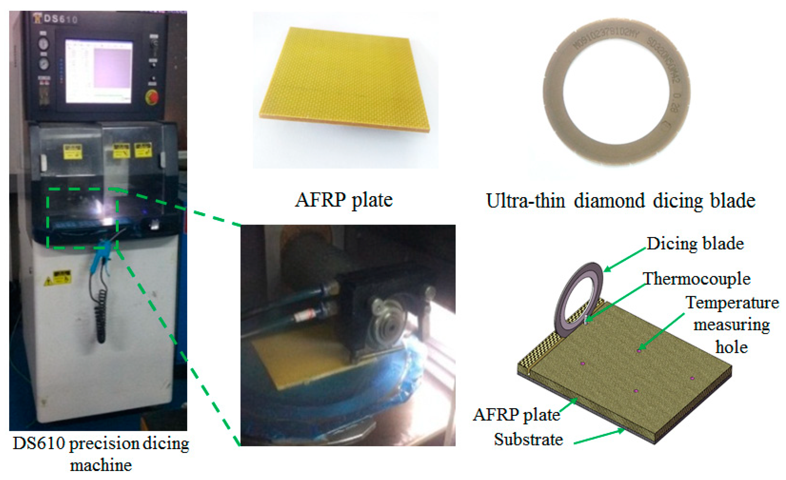
In view of the above two reasons, the ultra-thin diamond dicing blade was used to cut AFRP composites in this research. The ultra-thin diamond dicing blade is made of micro powder diamond particles and binder by hot pressing sintering [
22]. First, the diameter of the abrasive particle on the dicing blade is in the micron scale, which is in the order of magnitude with the diameter of the aramid fiber. The cutting edge size of the abrasive particle is far less than the diameter of the fiber, so that the aramid fiber can be cut neatly in sub-fiber scale. Secondly, the maximum spindle speed of the dicing machine can reach 40,000 r/min. Under high cutting speed, aramid fibers can be quickly cut off before deformation, so as to avoid various cutting damages. In addition, the thickness of ultra-thin diamond dicing blade is only 0.2 mm. Compared with the laser cutting and the abrasive water jet cutting, its kerf is narrower, which can save materials greatly and realize narrow slit cutting. At present, there is little research on cutting AFRP composites with the dicing blade. The process parameters for realizing high-quality and high-efficiency cutting of AFRP composites are not clear. In this paper, an ultra-thin diamond dicing blade is used for high-speed cutting of AFRP composites. Based on the study of the influence of cutting process parameters on the cutting force, cutting temperature, surface quality, tool wear and so on, the optimal process parameters of AFRP composite precision cutting are explored.
2. Prediction of Dicing Force with Dicing Blade
The dicing quality is significantly affected by the dicing force. Therefore, the dicing force should be studied first. The dicing force is derived from the elastic deformation, plastic deformation, chip formation of the workpiece and the friction between abrasive particles, binders and the workpiece. It mainly consists of chip deformation force and friction force.
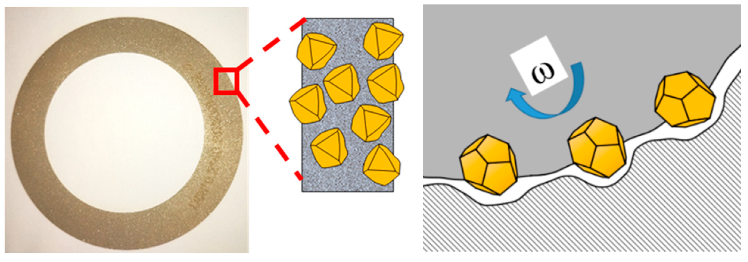
Figure 1 shows the schematic diagram of AFRP composite dicing. In the figure,
ω is the rotation speed of the dicing blade. A large number of diamond abrasive particles are distributed in the surface of the dicing blade. Each abrasive particle can be regarded as a micro cutter. The dicing process can be regarded as the collaborative cutting of many micro cutters. Therefore, the dicing force of a single abrasive particle should be analyzed first, and then multiplied by the total number of abrasive particles working simultaneously to establish the total dicing force model of the dicing blade.
2.1. Dicing Force Model of the Single Abrasive Particle
The dicing force of a single abrasive particle
Fg can be divided into the normal dicing force
Fgn and the tangential dicing force
Fgt. A single diamond abrasive particle can be approximately regarded as a conical indenter, as shown in
Figure 2. Under the action of load
p, the abrasive particle or indenter is pressed into the surface of AFRP composites, resulting in plastic deformation and indentation. The relationship between the load and the hardness of the material is [
23]:
where,
p is the load,
a is the indentation size,
ξ is the geometric factor of the indenter. For the Vickers indenter,
ξ = 2.
H is the hardness of the material.
It can be seen from
Figure 2 that the characteristic size of the indentation is:
The load or normal dicing force can be determined by the indentation depth or the chip thickness
h of the abrasive particle. Only half of the abrasive particle is subjected to force in the dicing process, and the state of the abrasive particle is much more complex than that of the indenter, so the relationship between the chip thickness
h and the normal dicing force
Fgn caused by chip deformation can be rewritten as:
where,
is a constant between 0 and 1.
θ is half vertex angle of the abrasive particle.
According to the geometric analysis, the ratio of normal and tangential dicing force of a single abrasive particle caused by chip deformation is [
24]:
Then the tangential dicing force
Fgt of a single abrasive particle is:
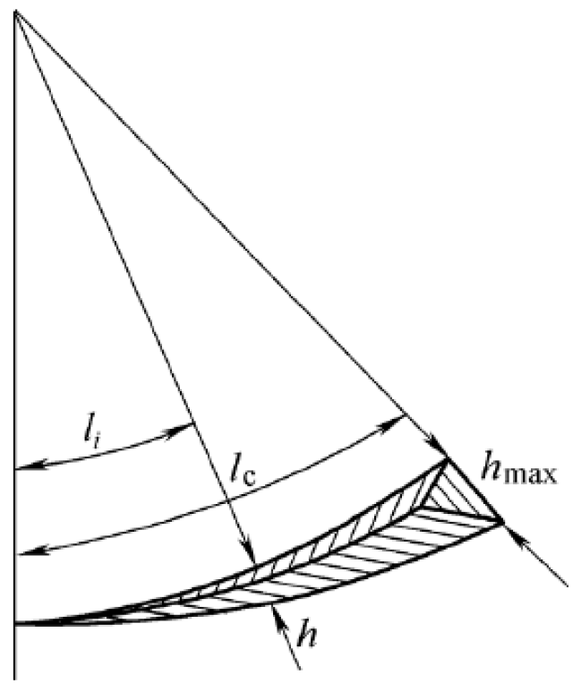
2.2. Maximum Undeformed Chip Thickness
The interference between a single abrasive particle and the workpiece material is shown in
Figure 3. The shadow part is an undeformed chip. In order to simplify it, the shape of the chip is approximately regarded as a triangle. Then the maximum undeformed chip thickness
hmax can be expressed as [
25]:
where,
N is the number of the effective abrasive particles per unit area,
vs is the cutting speed of dicing blade,
vw is the feed speed of worktable,
ap is the dicing depth, and
ds is the diameter of dicing blade.
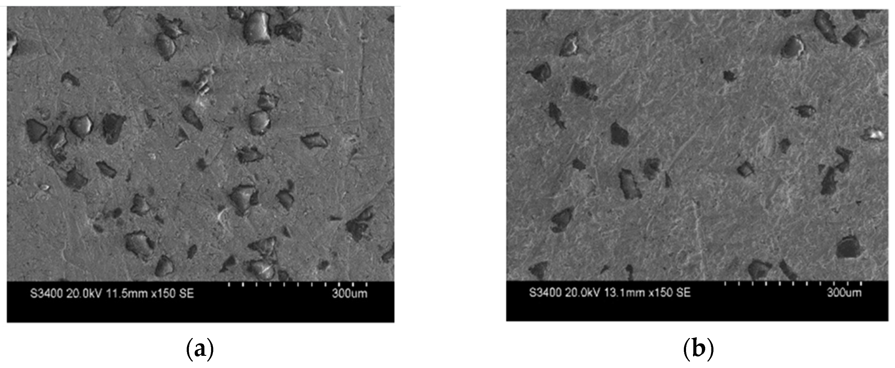
2.3. Number of Effective Abrasive Particles Per Unit Area on the Surface of the Dicing Blade
The dicing blade was sampled and observed many times under an Hitachi S-3400N scanning electron microscope. The distribution of abrasive particles on the surface is shown in
Figure 4. It can be seen that the distribution is generally uniform. The typical part with relatively dense distribution is shown in
Figure 4a, and the typical part with relatively sparse distribution is shown in
Figure 4b. Through statistics, the number of effective abrasive particles per unit area is about 50–60, with an average of 55.
2.4. Dicing Force Model of the Dicing Blade
The normal dicing force
Fn and tangential dicing force
Ft acting on the diamond dicing blade are, respectively, equal to the sum of the normal force and tangential force of all effective abrasive particles on the contact surface between the workpiece and the dicing blade, which can be expressed as:
where,
A1 is the contact area between the workpiece and the dicing blade. From the geometric relationship,
A1 is equal to the product of the contact arc length
ls and the width of the dicing blade
b. When the machined surface is flat, because
vw/
vs is very small, the contact arc length between the dicing blade and the workpiece is [
26]:
The normal dicing force
Fgn and the tangential dicing force
Fgt of a single abrasive particle are, respectively, brought into the Equations (7) and (8). The normal dicing force
Fn and the tangential dicing force
Ft of the dicing blade can be obtained as follows:
Dicing force
F can be expressed as:
For the dicing blade used in this paper, dicing blade diameter ds = 58 mm, dicing blade width b = 0.2 mm, abrasive particle half vertex angle θ = 75°. During the dicing process, the undeformed chip thickness h of each abrasive particle gradually increases from 0 to hmax. In order to simplify the calculation, h is approximately taken as 1/2 of the maximum hmax.
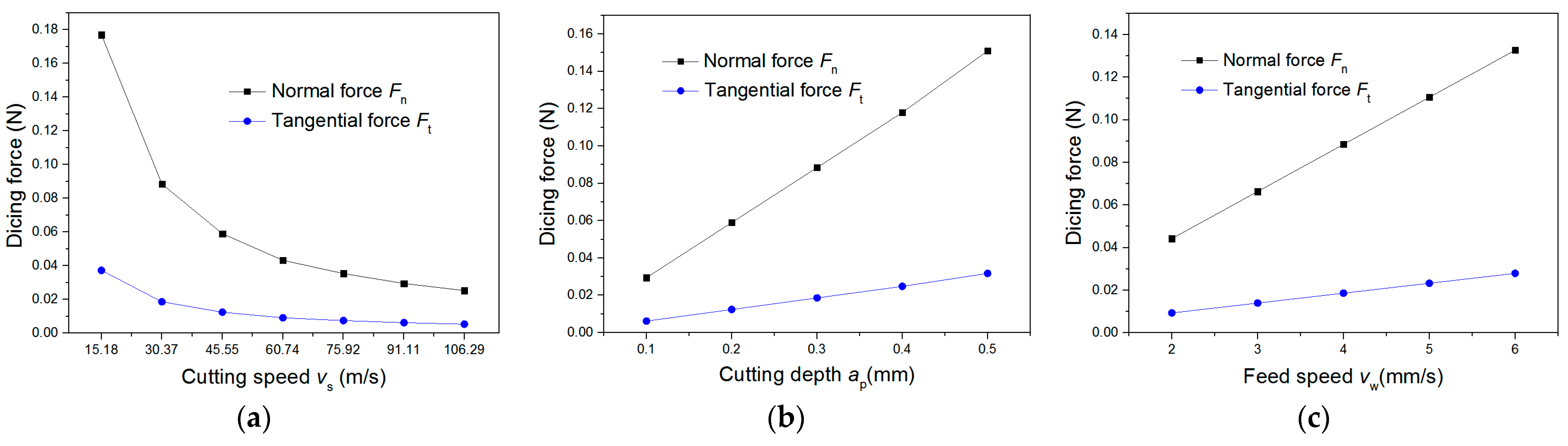
Through the above dicing force model, the variation of the calculated dicing force with process parameters is shown in
Figure 5. When the influence of the cutting speed on the dicing force is studied, the cutting depth
ap is fixed at 0.3 mm, and the workpiece feed speed
vw is fixed at 4 mm/s. When the influence of the cutting depth
ap on the dicing force is studied,
vs is fixed at 30.37 m/s (spindle speed
n = 10,000 r/min), and
vw is fixed at 4 mm/s. When the influence of the workpiece feed speed
vw on the dicing force is studied,
ap is fixed at 0.3 mm, and
vs is fixed at 30.37 m/s. It can be seen from
Figure 5 that the dicing force increases with the decrease of the cutting speed due to the decrease of the undeformed chip thickness. When the cutting speed is lower than 30.37 m/s, the dicing force increases sharply. When the cutting speed is higher than 60.74 m/s (spindle speed
n = 20,000 r/min), the dicing force is relatively small and changes little with the cutting speed. In addition, the comprehensive effects of the cutting depth
ap and the feed speed
vw on the undeformed chip thickness
h and contact arc length
ls make the dicing force change almost linear.
Through the above analysis, if only the dicing force is considered, it is suitable to select high cutting speed, small cutting depth and feed speed for AFRP dicing. However, machine vibration, dicing temperature, tool wear and other factors which will also affect the dicing quality are not considered in the dicing force model. In addition, the processing efficiency should also be considered in the selection of process parameters. Therefore, dicing process experiments are also needed. Through comprehensive analysis of the theoretical and experimental results, the optimal process parameters for high-quality and high-efficiency AFRP dicing will be explored.
4. Results and Discussion
4.1. Analysis of Orthogonal Experiment Results
4.1.1. Surface Morphology of AFRP Cutting with Dicing Blade
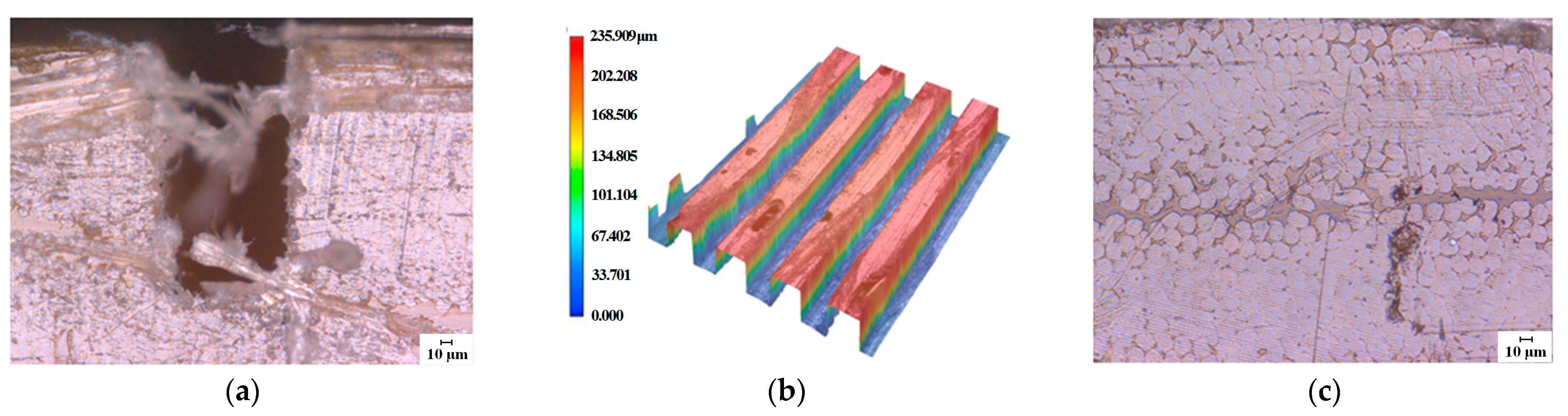
The surface morphology of the AFRP composites after cutting is shown in
Figure 7.
Figure 7a,b are the side and three-dimensional topography of the cutting groove, respectively. It can be seen that since the material at the edge of the workpiece in a weak constraint state, the matrix cannot provide effective support for the aramid fibers. Moreover, high toughness aramid fibers are not easy to be cut off. Under the thrust of the tool, the fibers are easy to peel off from the matrix, resulting in a small amount of burrs on the upper and side edges of the groove. There is no material flanging at the entrance and exit that often occurs in AFRP cutting. The fibers inside the groove are well-supported, so there is no obvious burr.
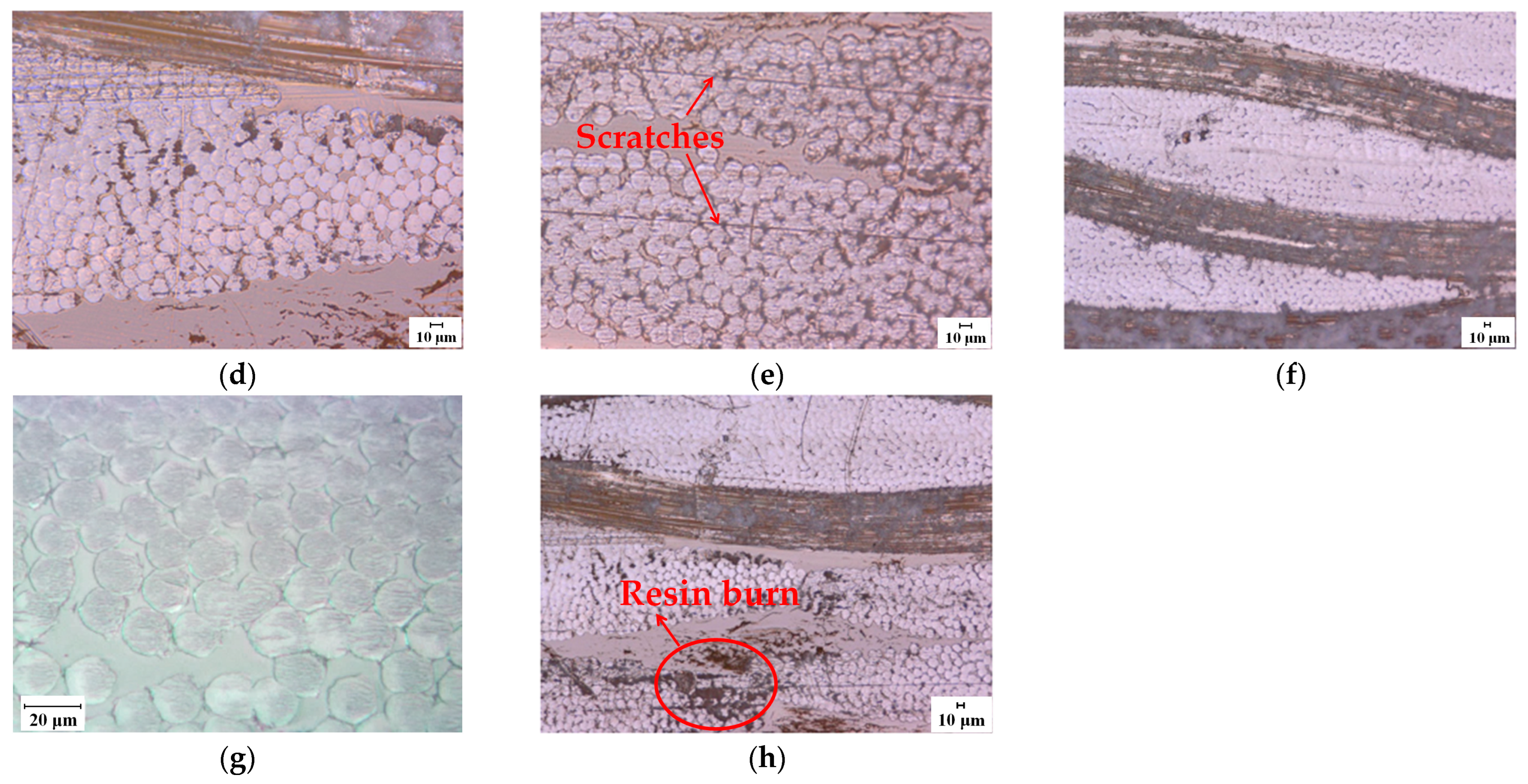
Figure 7c–h shows the surface topography of the groove after cutting. Where,
Figure 7c–g shows the surface morphology obtained under different cutting depths and feed speeds when the cutting speed is 91.11 m/s. It can be seen that the cutting surface is smooth, the cross sections of fibers are relatively flat, and there is no obvious burr, wire drawing, delamination, resin matrix cracking and other common cutting damages which often occur in AFRP cutting.
In the process of AFRP dicing, the size of the abrasive particle on the dicing blade is in the micron scale. The size of the cutting edge of the abrasive particle is far less than the diameter of the aramid fiber, so that they can be cut neatly in sub-fiber scale. In addition, the high speed of the dicing blade makes the fibers with high toughness rapidly cut off before deformation, so as to avoid various cutting damages. Therefore, the high-speed precision dicing method adopted in this paper is different from other cutting methods in the material removal mechanism. It can effectively reduce the damages caused by tool size and cutting speed. In addition, some slight scratches can be seen on the surface. The reason is that some sharp abrasive particles protrude from the surface of the dicing blade and do not fall off in time. The scratch can be improved by regularly trimming the dicing blade.
Figure 7h shows the surface morphology of No. 16 experiment, that is, when the cutting speed is 106.29 m/s, the cutting depth is 0.5 mm and the feed speed is 2 mm/s. It is found that when the process parameters are taken as high cutting speed, large cutting depth and low feed speed, the burn phenomenon appears on the cutting surface.
4.1.2. Influence of Cutting Parameters on Surface Roughness
Surface roughness is an important indicator for measuring the cutting quality of composite materials. The surface roughness
Ra of the AFRP plate after dicing was measured. The results are shown in
Table 4. Blank columns in the table are to verify whether there is any interaction between the selected experimental factors that cannot be ignored, or whether other factors which have great influences on the results are omitted. As can be seen from the table,
Ra values range from 38 to 158 nm, which is far lower than the value obtained by low-temperature milling and abrasive water jet machining [
12,
27].
In the table, Ki represents the sum of the corresponding experimental results when the level in any column is i (i = 1, 2, 3, 4). ki represents the arithmetic mean of Ra when the factor of any column is taken as level i. R is the range between the levels of a certain factor. R = max{K1, K2, K3, K4}-min{K1, K2, K3, K4}. According to the range analysis, the range of each column is not equal, indicating that each factor has different influence on the experimental results. Since RA > RC > RB, the sequence of the factors from primary to secondary is: A (cutting speed), C (feed speed) and B (cutting depth).
In order to further analyze the significance of each factor on the surface roughness, the results were analyzed by analysis of variance and F test.
The results of the orthogonal experiment were analyzed by analysis of variance and
F test. The average value of
Ra for the 16 experiments is:
The sum of squares of factor A is:
where,
,
,
and
are, respectively, the average values of each level of factor A. Similarly, the sum of squares
SB of factor B, the sum of squares
SC of factor C and the sum of squares
Se of errors can be obtained.
The sum of squares of total variation is:
The results of analysis of variance and
F test are shown in
Table 5. Factor A (cutting speed) has a significant effect on the surface roughness. Factor C (feed speed) has a certain influence on the surface roughness. Factor B (cutting depth) has little effect on the surface roughness.
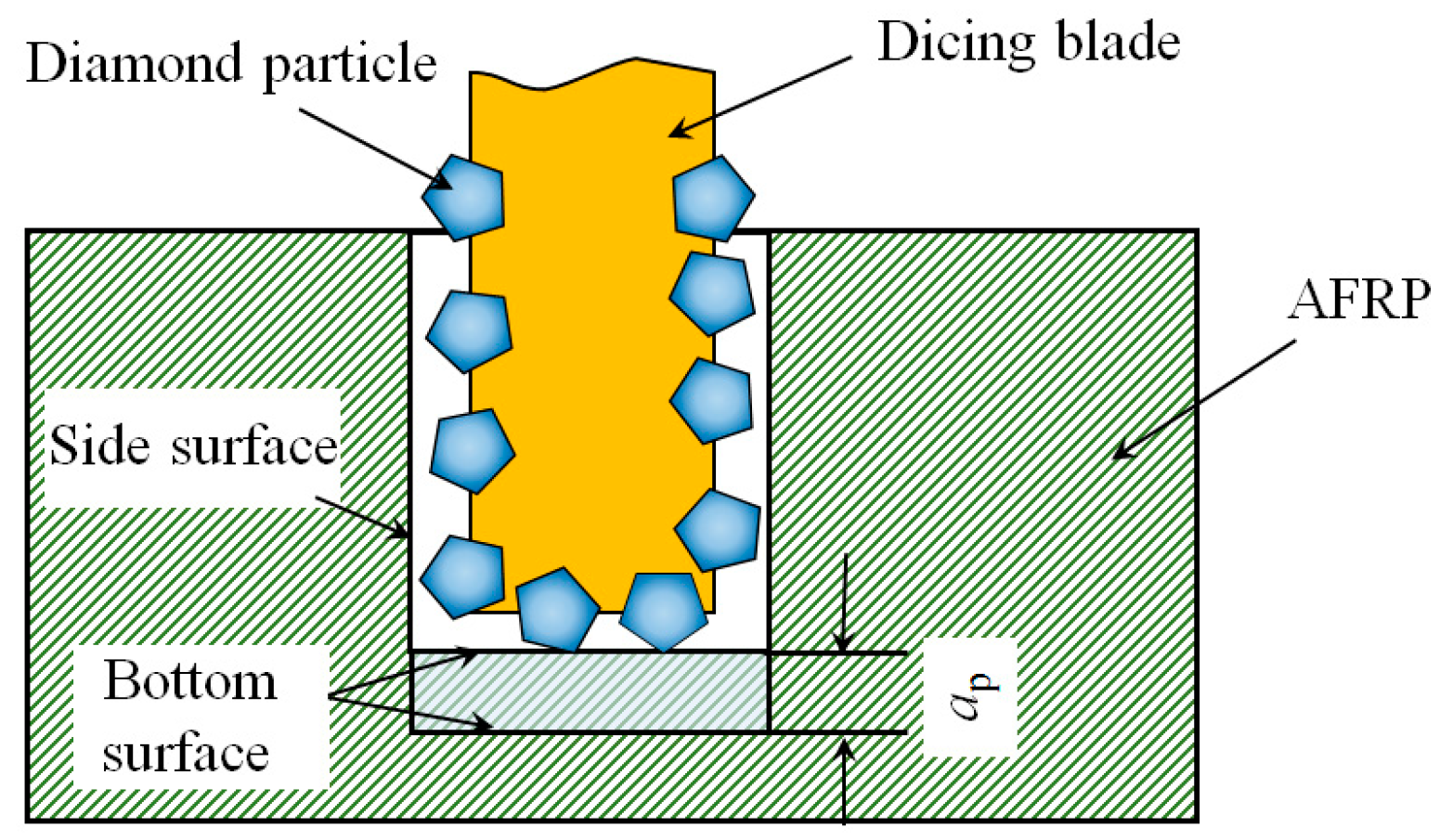
Generally, the cutting depth has a great effect on the surface roughness. But, dicing process is different from general cutting or grinding. As shown in
Figure 8, two kinds of surfaces are formed during dicing process, that is, the side surface of the groove and the bottom surface of the groove. Usually, with the increase of the cutting depth, the surface roughness of the bottom surface will increase. For the side surface, the increase of cutting depth will increase the number of abrasive particles involved in grinding. This will increase the friction between the tool and workpiece and increase the cutting force and cutting temperature slightly. However, the cutting depth of each abrasive particle in the side surface has not changed. Therefore, the surface quality of the side surface after dicing is little affected by the cutting depth. For AFRP edge cutting, the bottom surface disappears after cutting. Only the surface roughness of the side surface was measured after the experiment.
4.2. Variation of Cutting Thermal with Cutting Parameters
Besides the surface roughness, the surface quality of AFRP composites is also affected by various kinds of damages. In particular, the thermal conductivity of the AFRP composites is only approximately 1 W/(m·°C), which is about 1/50 of that of the 45 steel. During the dicing process, with the high-speed rotation of the dicing blade, the violent friction between a large number of abrasive particles and materials produces a great deal of cutting heat, which is not easy to dissipate. In addition, the heat resistance of the epoxy resin is poor. When the dicing temperature exceeds the glass transition temperature of the epoxy resin, AFRP composites will be burned. The burn phenomenon is also observed in
Figure 7. In order to analyze the influence of process parameters on cutting heat in detail, a single factor experiment was carried out. The specific process parameters are shown in
Table 3. Other experimental conditions are the same as those of the orthogonal experiment. The temperature measurement method using embedded thermocouple has been introduced in
Section 3.2. Three experiments were carried out under the same parameter. The average value of the three experiments is taken as the temperature value under this parameter.
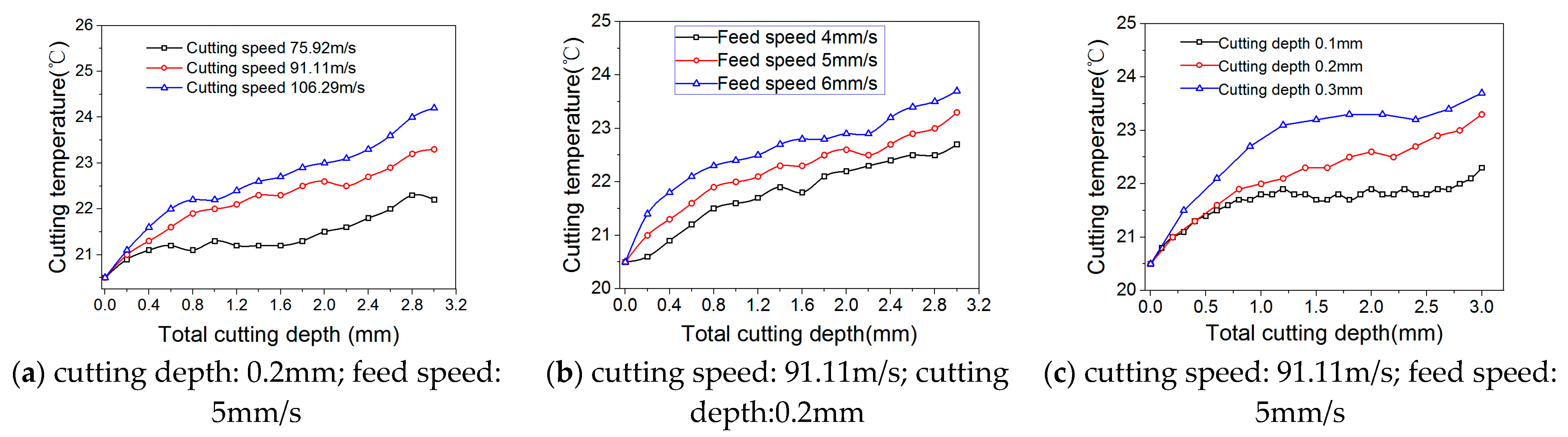
Figure 9 shows the variation curve of cutting temperature with total cutting depth under different process parameters. It can be seen that the influence of each process parameter on cutting temperature is cutting speed > cutting depth > feed speed. From
Figure 9a, the cutting temperature increases with the increase of cutting speed. This is because when the feed speed and cutting depth are the same, the cutting time is certain. Then, the higher the cutting speed, the higher the contact frequency between the tool and the workpiece material will be, resulting in the increase of friction heat. The increase of contact frequency also intensifies the wear of the dicing blade and further increases the cutting temperature. It can be seen from
Figure 9b that the cutting temperature increases with the increase of feed speed. This is because when the cutting speed and cutting depth are the same, the material to be cut per unit time increases with the increase of feed speed. The increase of material deformation and contact friction between tool and workpiece leads to the increase of cutting heat.
Figure 9c shows when the cutting speed and feed speed are the same, the cutting temperature increases with the increase of cutting depth. This is because when the cutting depth increases, the contact area and friction between the tool and the workpiece increase, resulting in the rise of cutting temperature.
4.3. Determination of the Optimal Parameters
The optimal scheme is a combination of factors with superior levels in the range of experimental parameters. The determination of the optimum level of each factor is related to the index of the experiment, that is, the surface roughness Ra of the AFRP composites. The smaller Ra means the better surface quality, so it is necessary to find the level corresponding to the minimum value of Ki (ki) in each column.
Column of factor A: K1 > K2 > K4 > K3
Column of factor B: K4 > K3 > K2 > K1
Column of factor C: K3 > K2 > K1 > K4
Therefore, the optimal scheme is A3B1C4, that is, the cutting speed is 91.11 m/s, the cutting depth is 0.2 mm, and the feed speed is 5 mm/s.
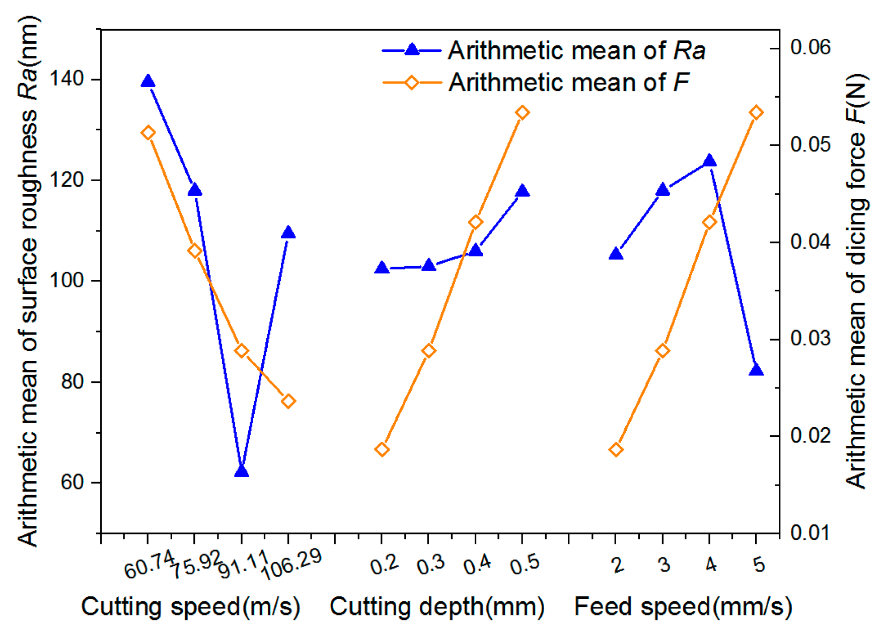
In order to analyze whether the level of factors determined by the above optimal scheme is appropriate, the dicing force
F of each factor under each level are calculated by the dicing force model and listed in
Table 4. Then, each factor is taken as the abscissa, the arithmetic mean of the dicing force
F (in
Table 4) and the surface roughness
Ra (
ki in
Table 4) at each level are taken as the ordinate,
Figure 10 can be obtained. It can be seen that the surface quality gradually becomes worse as the cutting depth increases from 0.2 to 0.5 mm. This is because as the cutting depth increases, the undeformed chip thickness increases and the required dicing force increases, making the cutting quality worse. In addition, as the feed speed decreases from 5 to 2 mm/s, the surface quality also deteriorates. The reason may be that reducing the feed speed can reduce the dicing force in the cutting process. However, when the feed speed is too slow, the friction between the tool flank and the machined surface intensifies. Due to the poor heat resistance of epoxy resin matrix, it is easy to soften or even burn under severe friction and thus destroys the quality of the machined surface. As shown in
Figure 7h, resin burn occurs when the cutting speed is 106.29 m/s, the cutting depth is 0.5 mm and the feed speed is 2 mm/s. There was also a special smell during No.16 experiment.
Overall, in the range of the orthogonal experimental parameters, the cutting surface quality is the best when the cutting speed is 91.11 m/s, the cutting depth is 0.2 mm and the feed speed is 5 mm/s. In addition, the cutting surface quality tends to improve with the decrease of cutting depth and the increase of feed speed. This means that if the cutting depth is reduced or the feed rate is increased properly, a better process scheme may be obtained. Therefore, some new experiments need to be carried out beyond the range of the parameters of the orthogonal experiment.
4.4. Verification Experiment and Result Analysis
The results of the above orthogonal experiments show that the cutting surface quality is the best when the cutting speed is 91.11 m/s. Therefore, verification experiment was designed to explore the optimal parameters of the cutting depth and the feed speed. The process parameters are shown in
Table 6. The cutting speed was fixed at 91.11 m/s, and the cutting depth was reduced to 0.1 mm on the basis of 0.2 mm of the orthogonal experiments. The feed speed was increased to 6, 7 and 8 mm/s on the basis of 5 mm/s of the orthogonal experiments.
4.4.1. Surface Roughness and Maximum Current of Spindle
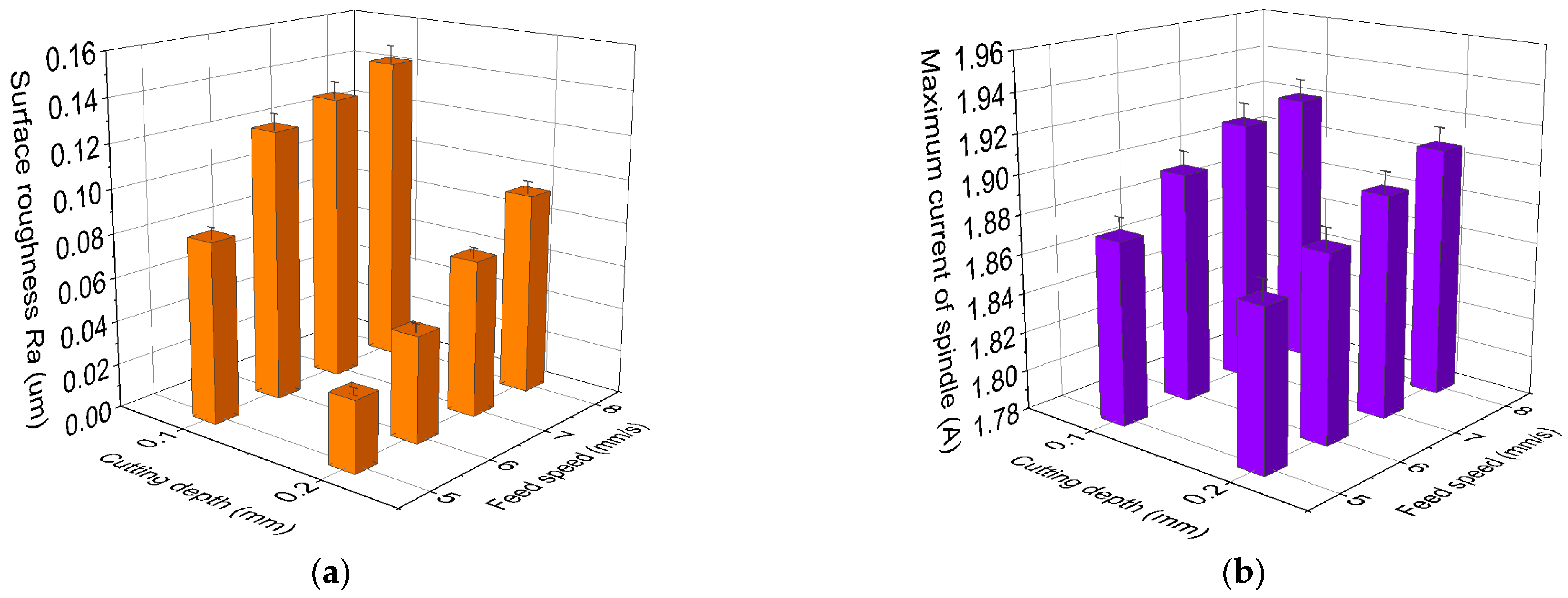
The maximum current of the spindle during the experiment and the surface roughness
Ra of the AFRP composites after dicing are shown in
Figure 11. It can be seen that under the same spindle speed, the variation trend of the maximum current and the surface roughness with the process parameters are consistent. When the cutting depth is constant, the maximum current of spindle increases and the cutting surface quality becomes worse with the increase of the feed speed. The increase of the maximum current of the spindle indicates that the cutting power or dicing force increases. From
Figure 5, the dicing force increases with the increase of the feed speed. Abrasive particles are easier to wear and fall off under large dicing force. The cutting effect of the blunt dicing blade is weakened, resulting in deterioration of the cutting surface quality.
When the cutting depth is reduced from 0.2 to 0.1 mm, the surface quality after cutting also becomes worse. The reason for this phenomenon can also be obtained by analyzing the trend of the maximum current of the spindle. At the same feed speed, when the cutting depth is reduced, the maximum current of the spindle increases. This is because when the total cutting depth is certain, the smaller the depth of each cut, the more cutting times of the tool. That is, the number of contacts between the tool and the AFRP composites increases, resulting in the intensification of tool wear and the reduction of cutting surface quality. Therefore, in order to verify the above conjecture, tool wear should be analyzed.
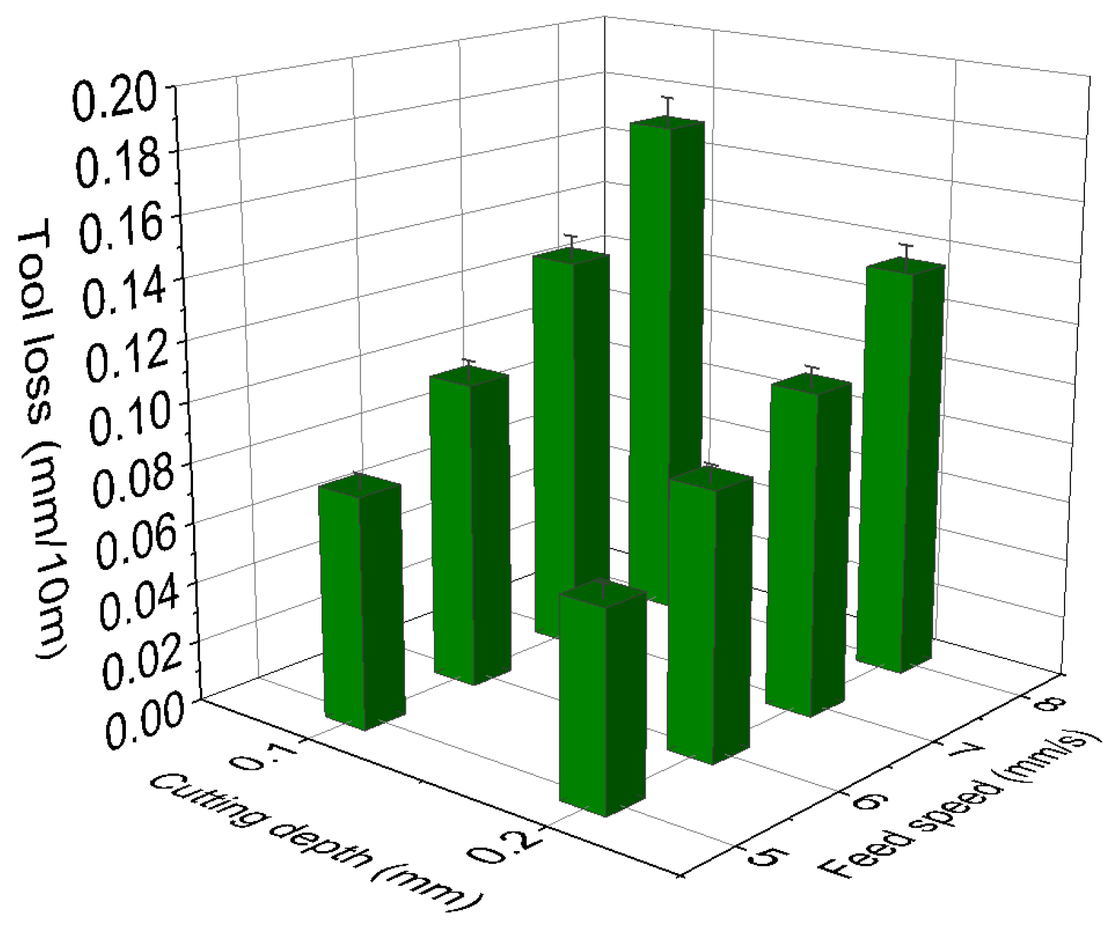
4.4.2. Tool Wear with Cutting Parameters
The degree of tool wear is quantitatively characterized by the amount of tool loss. The height between the tool and the bottom fixture is measured before and after each experiment. The amount of the tool loss is obtained from the two measured height difference. The measured tool loss is divided by the corresponding cutting distance, and the tool loss per cut 10 m length is obtained, as shown in
Figure 12. The comparison shows that under the same cutting speed, feed speed and coolant flow rate, the tool loss increases with the decrease of cutting depth. In addition, for the same cutting depth, the tool loss increases with the increase of feed speed. This trend is consistent with
Figure 11, which proves that the above conjecture is correct.
Based on the comprehensive analysis of the above results of orthogonal experiment and verification experiment, A
3B
1C
4 is the optimal process parameter. A
3B
1C
4 represents the cutting speed of 91.11 m/s, cutting depth of 0.2 mm and feed speed of 5 mm/s, which is the parameter of No. 1 experiment in the verification experiment. Under this process parameter, the surface roughness
Ra of AFRP composites after cutting is 32 nm, which is slightly better than the result of No. 10 (A
3B
2C
4) in the orthogonal experiment of 38 nm. It is proved that A
3B
1C
4 is indeed the optimal process parameter under the experimental conditions. A
3B
2C
4 represents the cutting speed of 91.11 m/s, cutting depth of 0.3 mm and feed speed of 5 mm/s. According to
Section 4.1.2, factor B (cutting depth) has little effect on the surface roughness of the side surface of the AFRP composites. Therefore, the cutting depth can be appropriately increased to achieve high machining efficiency.


