
Dual-Modal Hybrid Control for an Upper-Limb Rehabilitation Robot

 , ,
, ,
Abstract
:1. Introduction
2. Materials and Methods
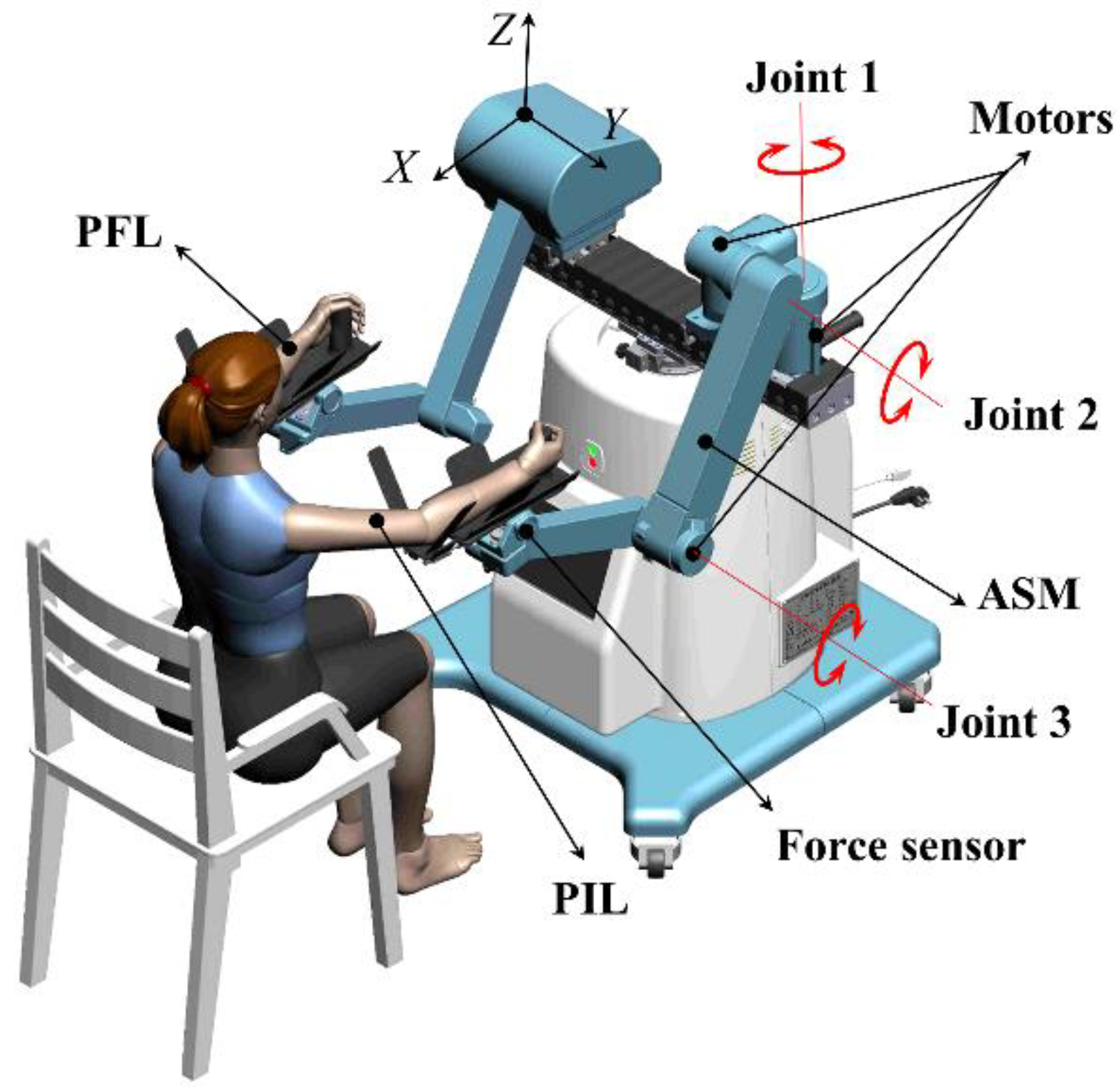
2.1. Upper Limb Rehabilitation Robot
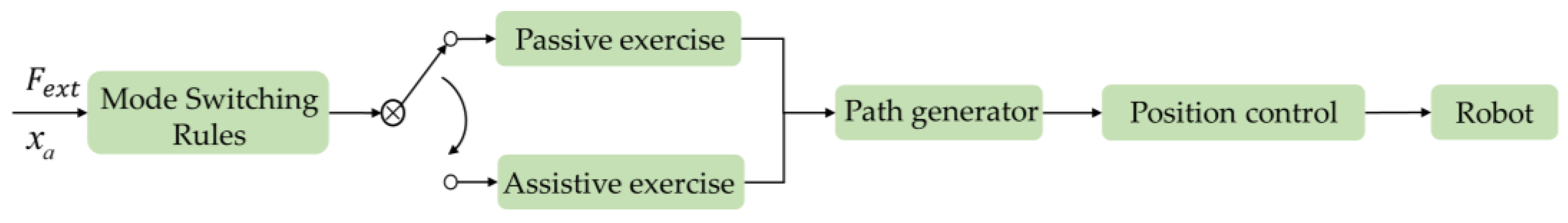
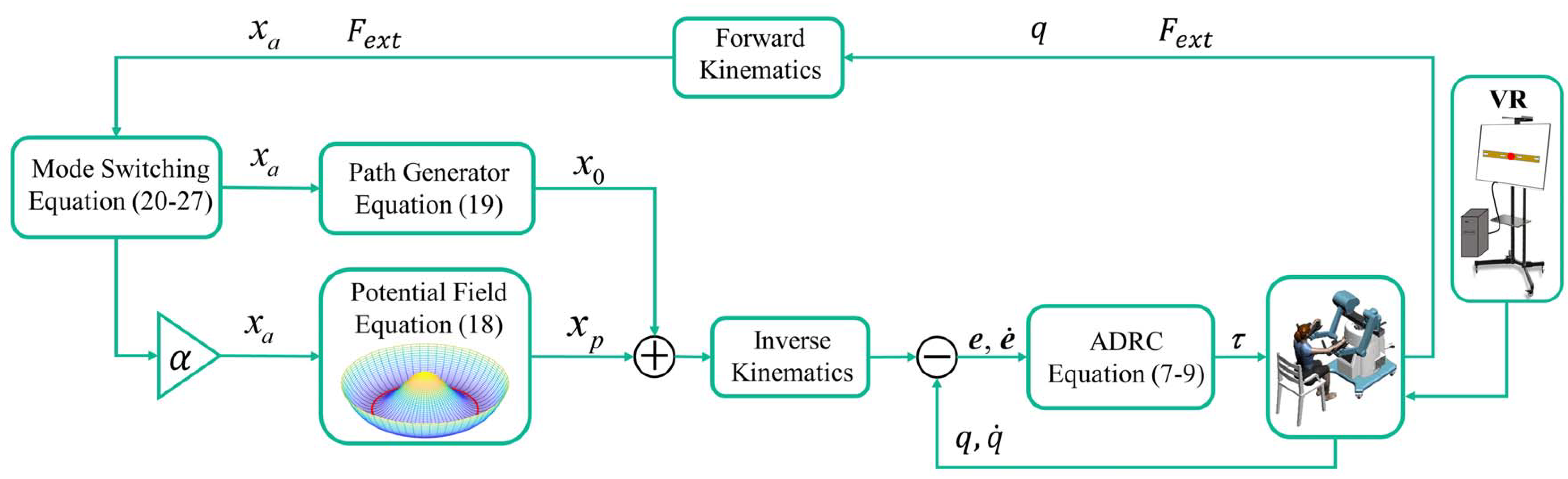
2.2. Overall Design of Control Strategy
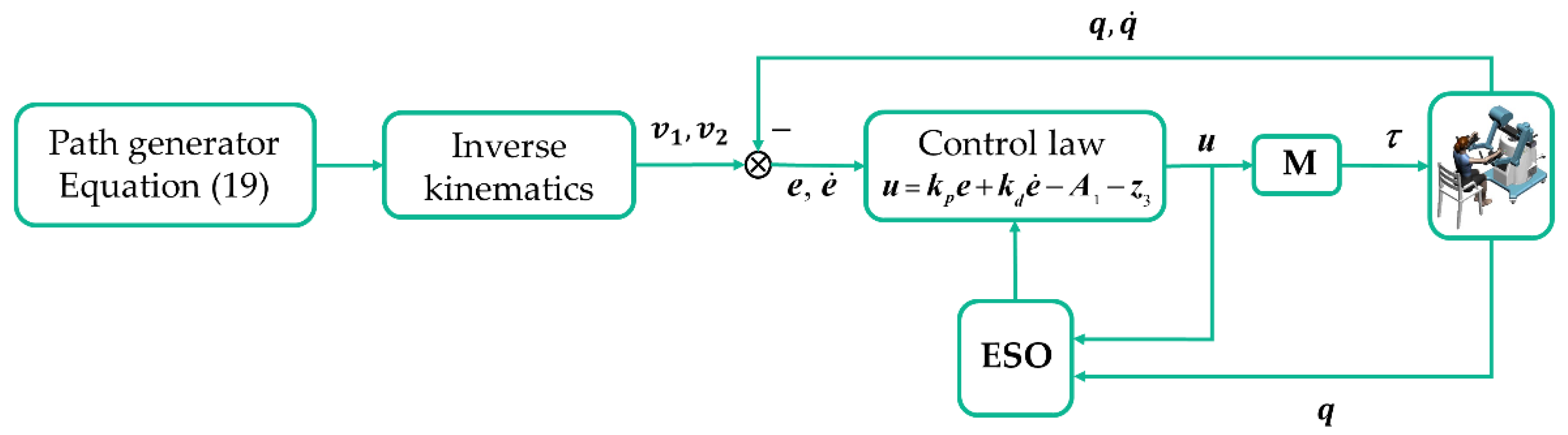
2.3. Design of Active Disturbance Rejection Position Controller
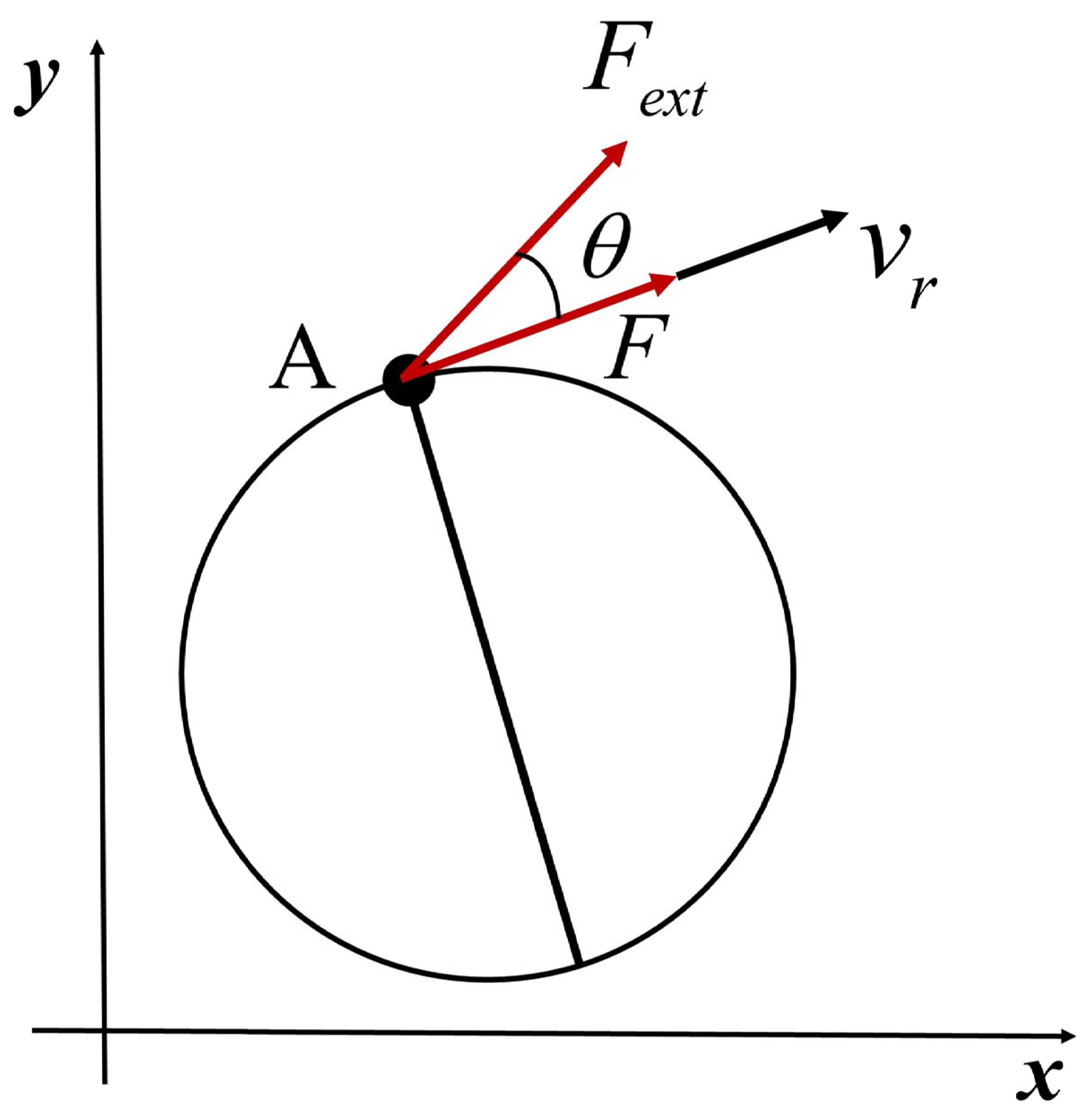
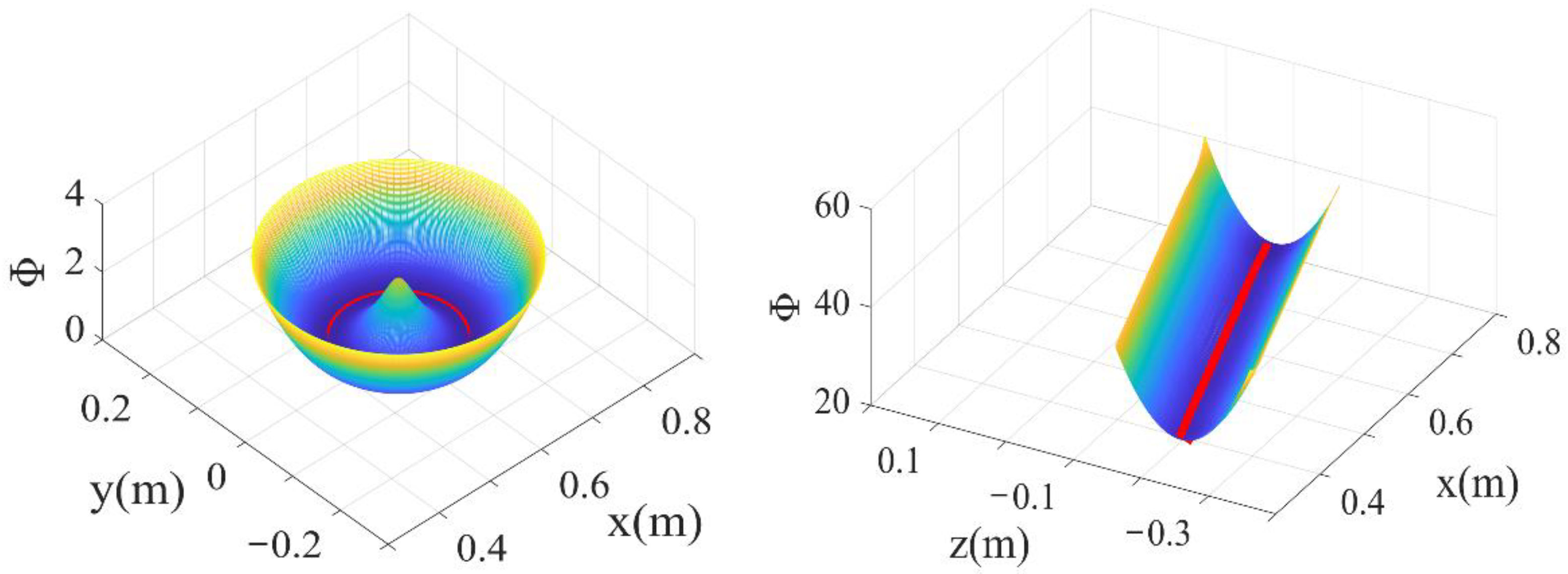
2.4. Potential Field Design
2.5. Dual-Modal Hybrid Self-Switching Control
2.6. Dual-Modal Self-Switching Rules
2.6.1. Reverse Switching Rule
2.6.2. Forward Switching Rule
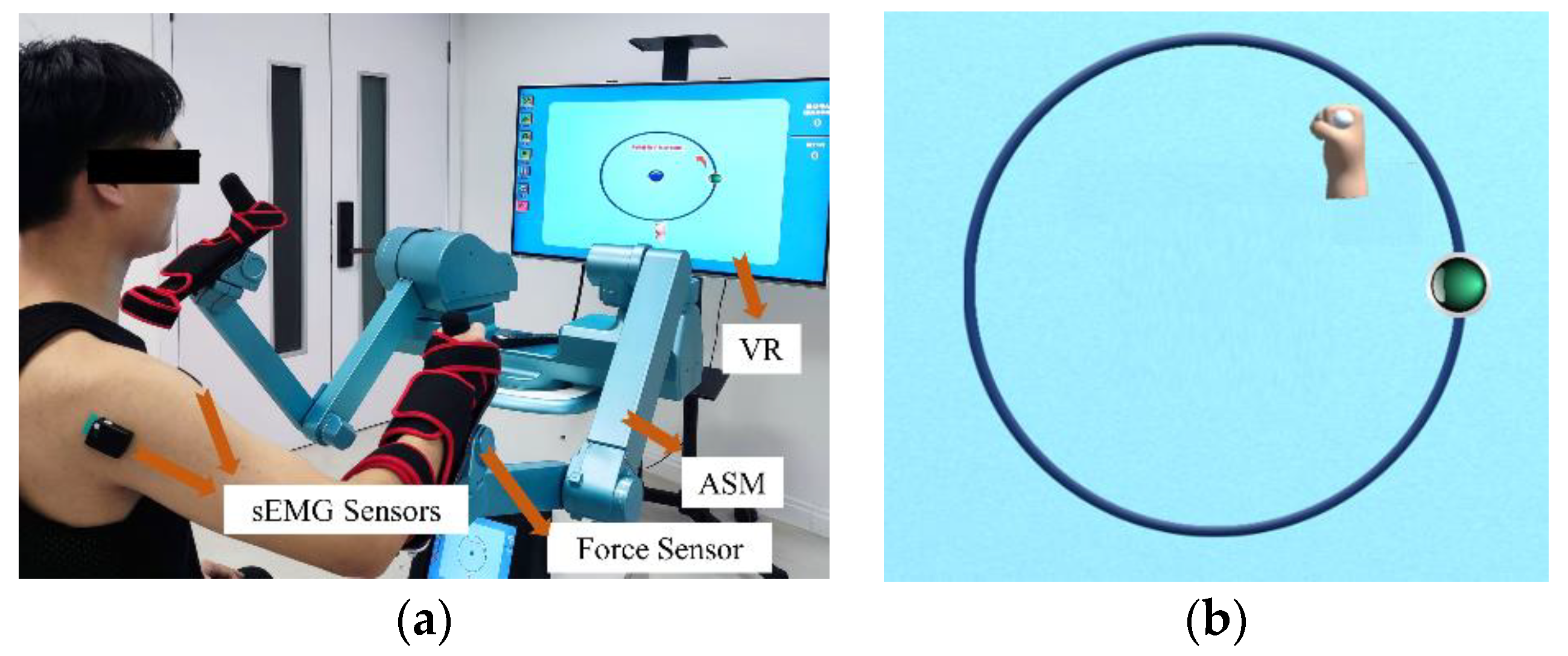
3. Results
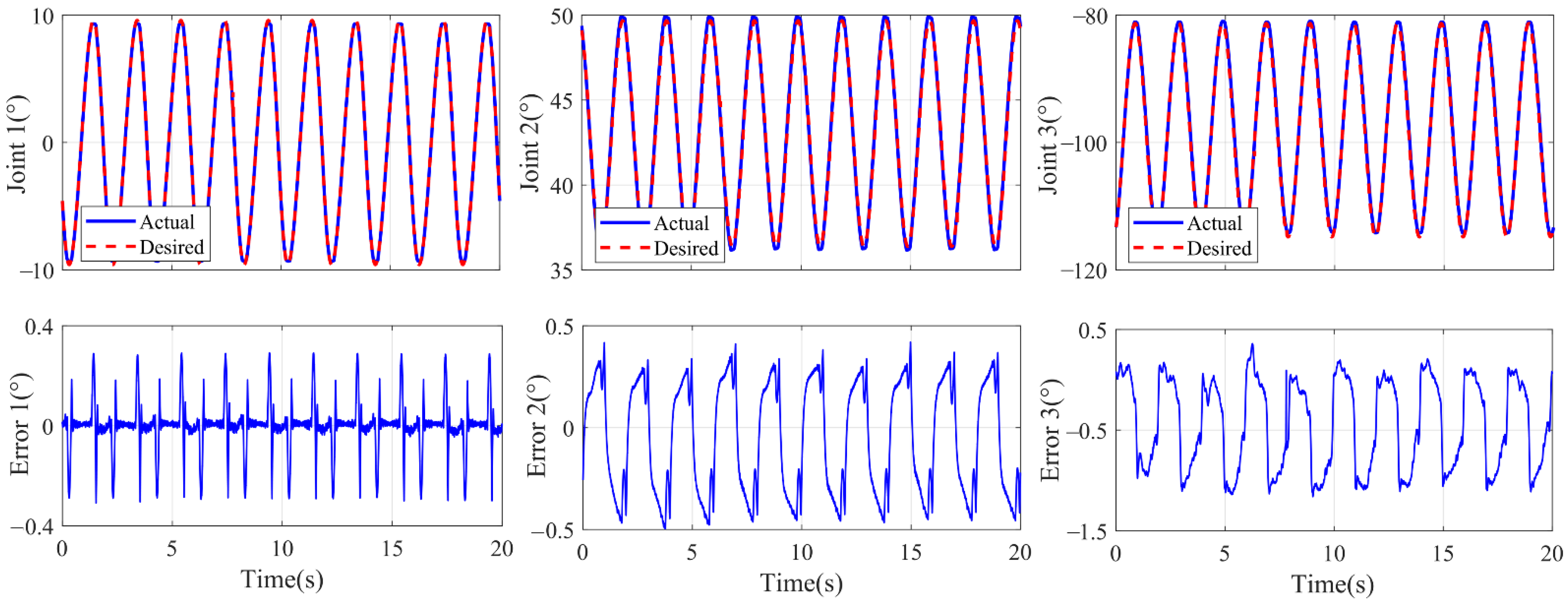
3.1. Experiment on Tracking Error
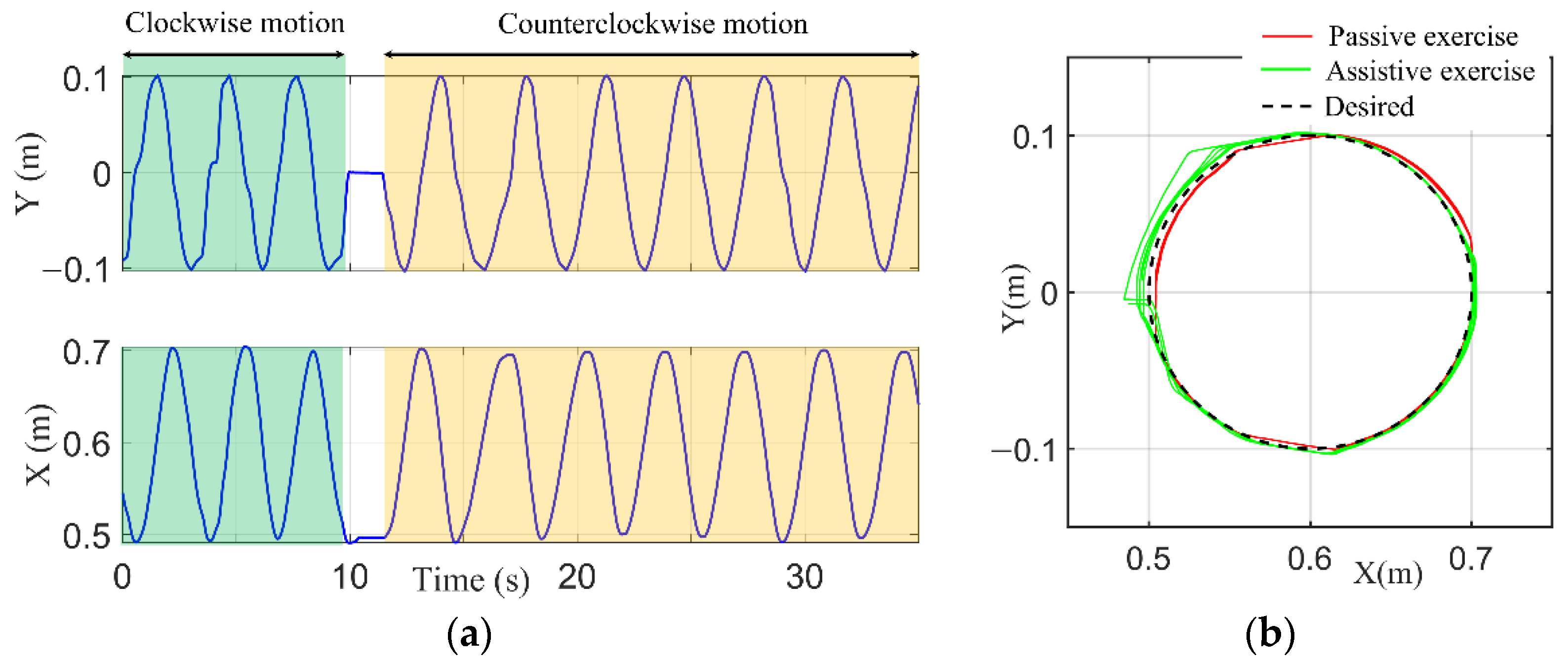
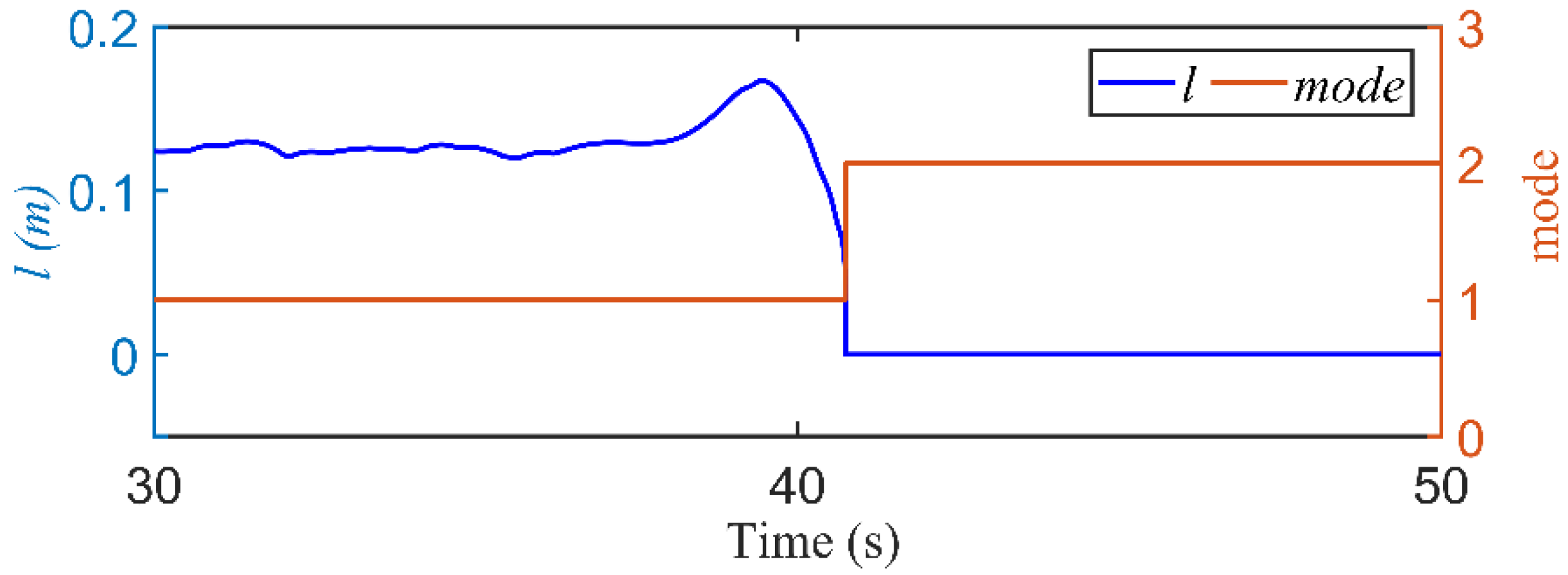
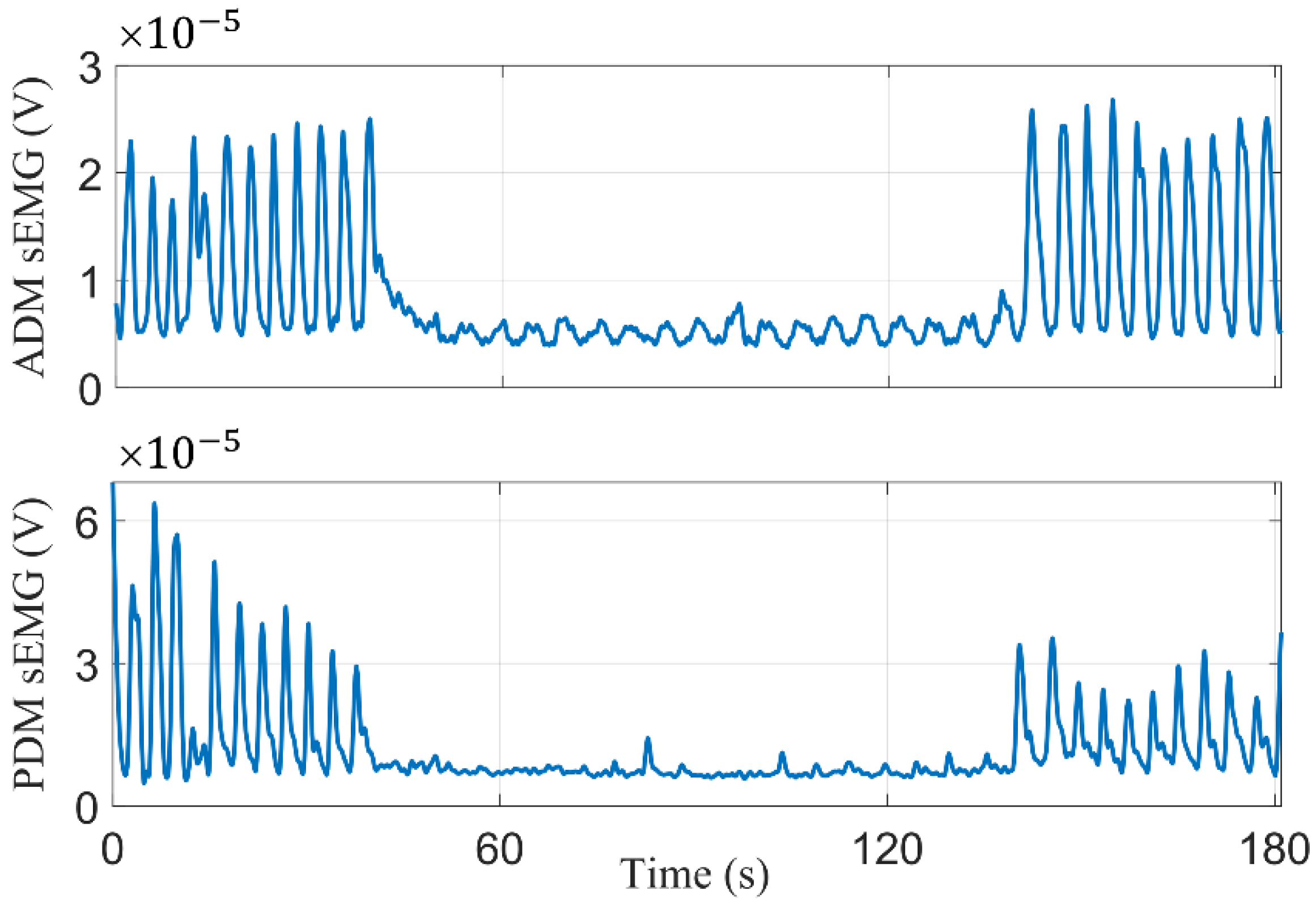
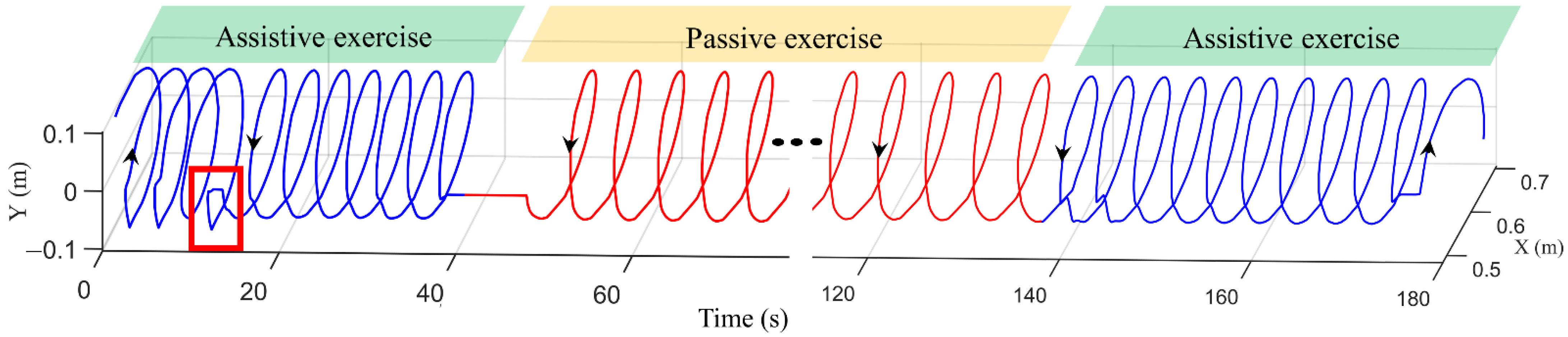
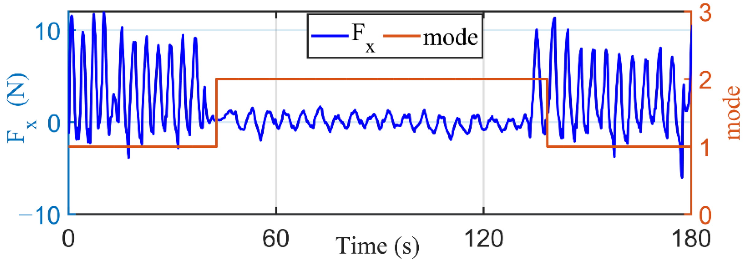
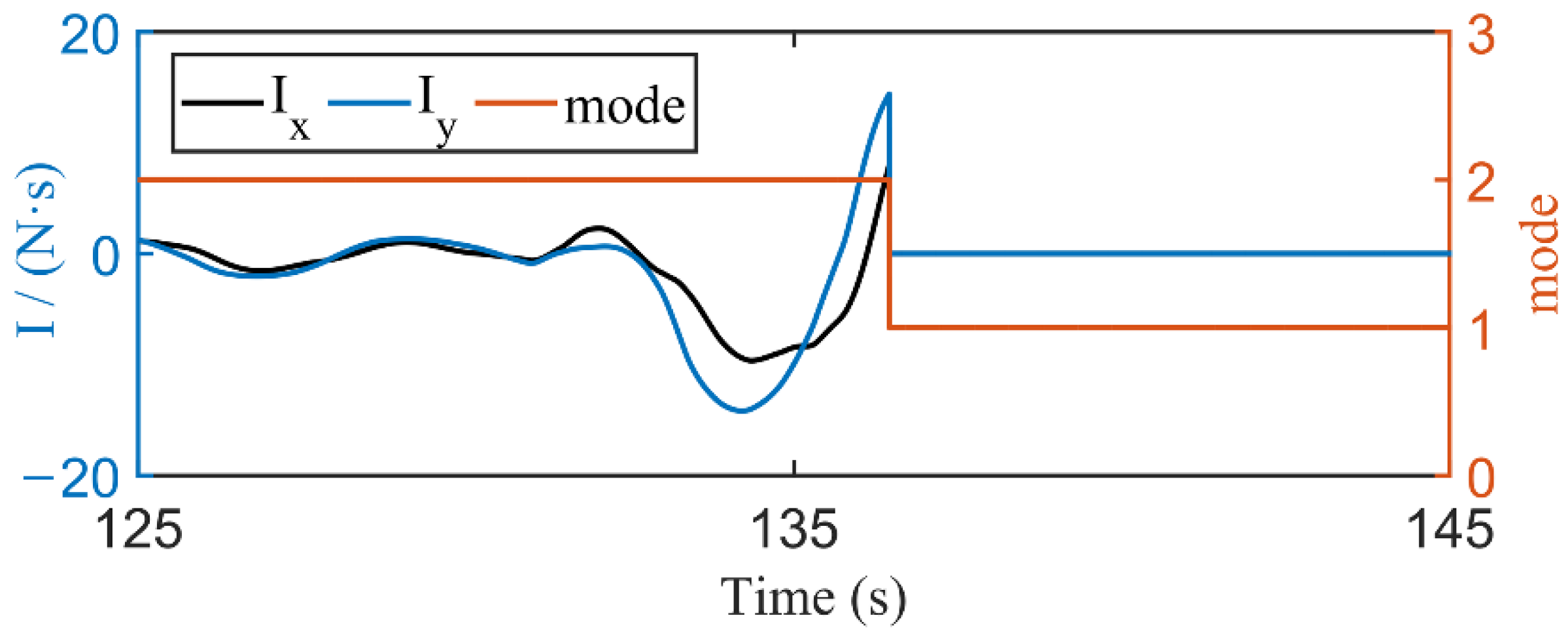
3.2. Dual-Modal Self-Switching Experiment
4. Discussion
5. Conclusions
Author Contributions
Funding
Institutional Review Board Statement
Informed Consent Statement
Data Availability Statement
Conflicts of Interest
References
- Everard, G.; Luc, A.; Doumas, I.; Ajana, K.; Stoquart, G.; Edwards, M.G.; Lejeune, T. Self-rehabilitation for post-stroke motor function and activity—A systematic review and meta-analysis. Neurorehabilit. Neural Repair 2021, 35, 1043–1058. [Google Scholar] [CrossRef] [PubMed]
- Krebs, H.I.; Hogan, N.; Aisen, M.L.; Aisen, B.T. Robot-aided neurorehabilitation. IEEE Trans. Rehabil. Eng. 1998, 6, 75–87. [Google Scholar] [CrossRef] [PubMed] [Green Version]
- Lum, P.S.; Burgar, C.G.; Shor, P.C.; Majmundar, M.; Van der Loos, M. Robot-assisted movement training compared with conventional therapy techniques for the rehabilitation of upper-limb motor function after stroke. Arch. Phys. Med. Rehab. 2002, 83, 952–959. [Google Scholar] [CrossRef] [PubMed] [Green Version]
- Zhang, L.; Guo, S.; Sun, Q. Development and assist-as-needed control of an end-effector upper limb rehabilitation robot. Appl. Sci. 2020, 10, 6684. [Google Scholar] [CrossRef]
- Miao, Q.; Zhang, M.M.; Wang, Y.P.; Xie, S.Q. Design and interaction control of a new bilateral upper-limb rehabilitation device. J. Healthc. Eng. 2017, 2017, 7640325. [Google Scholar] [CrossRef] [Green Version]
- Nef, T.; Mihelj, M.; Riener, R. ARMin: A robot for patient-cooperative arm therapy. Med. Biol. Eng. Comput. 2007, 45, 887–900. [Google Scholar] [CrossRef] [Green Version]
- Perry, J.C.; Powell, J.M.; Rosen, J. Isotropy of an upper limb exoskeleton and the kinematics and dynamics of the human arm. Appl. Bionics Biomech. 2009, 6, 175–191. [Google Scholar] [CrossRef] [Green Version]
- Kim, H.; Miller, L.M.; Fedulow, I.; Simkins, M.; Abrams, G.M.; Byl, N.; Rosen, J. Kinematic data analysis for post-stroke patients following bilateral versus unilateral rehabilitation with an upper limb wearable robotic system. IEEE Trans. Neural Syst. Rehabil. Eng. 2013, 21, 153–164. [Google Scholar] [CrossRef]
- Perry, J.C.; Rosen, J.; Burns, S. Upper-limb powered exoskeleton design. IEEE/ASME Trans. Mechatron. 2007, 12, 408–417. [Google Scholar] [CrossRef]
- Wu, Q.; Chen, Y. Development of an intention-based adaptive neural cooperative control strategy for upper-limb robotic rehabilitation. IEEE Robot. Autom. Lett. 2021, 6, 335–342. [Google Scholar] [CrossRef]
- Chen, C.F.; Du, Z.J.; Zhang, H.; Dong, W. Double-mode switching control of a lower limb exoskeleton based on flexible drive joint. Jiqiren/Robot. 2021, 43, 513–525. [Google Scholar]
- Li, Z.; Zuo, W.K.; Li, S. Zeroing dynamics method for motion control of industrial upper-limb exoskeleton system with minimal potential energy modulation. Measurement 2020, 163, 107964. [Google Scholar] [CrossRef]
- Reinkensmeyer, D.J.; Dewald, J.P.; Rymer, W.Z. Guidance-based quantification of arm impairment following brain injury: A pilot study. IEEE Trans. Rehabil. Eng. 1999, 7, 1–11. [Google Scholar] [CrossRef] [PubMed]
- Horton, S.; Howell, A.; Humby, K.; Ross, A. Engagement and learning: An exploratory study of situated practice in multi-disciplinary stroke rehabilitation. Disabil. Rehabil. 2011, 33, 270–279. [Google Scholar] [CrossRef] [PubMed]
- Lenzi, T.; Rossi, S.D.; Vitiello, N.; Carrozza, M.C. Intention-based EMG control for powered exoskeletons. IEEE Trans. Bio-Med. Eng. 2012, 59, 2180–2190. [Google Scholar] [CrossRef] [PubMed]
- Benitez, L.; Table, M.; Will, N.; Schmidt, S.; Jordan, M.; Kirchner, E.A. Exoskeleton technology in rehabilitation: Towards an EMG-based orthosis system for upper limb neuromotor rehabilitation. J. Robot. 2013, 2013, 610589. [Google Scholar] [CrossRef] [Green Version]
- Ho, N.S.K.; Tong, K.Y.; Hu, X.L.; Fung, K.L.; Wei, X.J.; Rong, W.; Susanto, E.A. An EMG-driven exoskeleton hand robotic training device on chronic stroke subjects: Task training system for stroke rehabilitation. In Proceedings of the 2011 IEEE International Conference on Rehabilitation Robotics, Zurich, Switzerland, 29 June–1 July 2011. [Google Scholar]
- Sharifi, M.; Behzadipour, S.; Salarieh, H.; Tavakoli, M. Assist-as-needed policy for movement therapy using telerobotics-mediated therapist supervision. Control. Eng. Pract. 2020, 101, 104481. [Google Scholar] [CrossRef]
- Luo, L.; Peng, L.; Wang, C.; Hou, Z.G. A greedy assist-as-needed controller for upper limb rehabilitation. IEEE Trans. Neural Netw. Learn. Syst. 2019, 30, 3433–3443. [Google Scholar] [CrossRef]
- Shahbazi, M.; Atashzar, S.F.; Tavakoli, M.; Patel, R.V. Robotics-assisted mirror rehabilitation therapy: A therapist-in-the-loop assist-as-needed architecture. IEEE/ASME Trans. Mechatron. 2016, 21, 1954–1965. [Google Scholar] [CrossRef]
- Wang, J.; Zhang, J.; Zuo, G.; Shi, C.; Guo, S. A reward-punishment feedback control strategy based on energy information for wrist rehabilitation. Int. J. Adv. Robot. Syst. 2020, 17, 1729881420940651. [Google Scholar] [CrossRef]
- Khansari-Zadeh, S.M.; Khatib, O. Learning potential functions from human demonstrations with encapsulated dynamic and compliant behaviors. Auton. Robot. 2017, 41, 45–69. [Google Scholar] [CrossRef]
- Najafi, M.; Rossa, C.; Adams, K.; Tavakoli, M. Using potential field function with a velocity field controller to learn and reproduce the therapist’s assistance in robot-assisted rehabilitation. IEEE/ASME Trans. Mechatron. 2020, 25, 1622–1633. [Google Scholar] [CrossRef]
- Burns, A.; Adeli, H.; Buford, J.A. Upper limb movement classification via electromyographic signals and an enhanced probabilistic network. J. Med. Syst. 2020, 44, 176. [Google Scholar] [CrossRef]
- Wang, D.; Zhang, X.; Chen, X.; Zhou, P. Application of wavelet packet transform on myoelectric pattern recognition for upper limb rehabilitation after stroke. In Proceedings of the 2014 36th Annual International Conference of the IEEE Engineering in Medicine and Biology Society, Chicago, IL, USA, 26–30 August 2014. [Google Scholar]
- Liparulo, L.; Zhang, Z.; Panella, M.; Gu, X.; Fang, Q. A novel fuzzy approach for automatic Brunnstrom stage classification using surface electromyography. Med. Biol. Eng. Comput. 2017, 55, 1367–1378. [Google Scholar] [CrossRef] [PubMed]
- Cai, S.; Chen, Y.; Huang, S.; Wu, Y.; Zheng, H.; Li, X.; Xie, L. SVM-based classification of sEMG signals for upper-limb self-rehabilitation training. Front. Neurorobot. 2019, 13, 31. [Google Scholar] [CrossRef] [PubMed] [Green Version]
- Akdoğan, E.; Aktan, M.E.; Koru, A.T.; Arslan, M.S.; Atlıhan, M.; Kuran, B. Hybrid impedance control of a robot manipulator for wrist and forearm rehabilitation: Performance analysis and clinical results. Mechatronics 2018, 49, 77–91. [Google Scholar] [CrossRef]
- Li, M.; Zhang, J.; Zuo, G.; Feng, G.; Zhang, X. Assist-as-needed control strategy of bilateral upper limb rehabilitation robot based on GMM. Machines 2022, 10, 76. [Google Scholar] [CrossRef]
- Li, C.B.; Pavelescu, D. The friction-speed relation and its influence on the critical velocity of stick-slip motion. Wear 1982, 82, 277–289. [Google Scholar]
- Potvin, J.R.; Brown, S.H.M. Less is more: High pass filtering, to remove up to 99% of the surface EMG signal power, improves EMG-based biceps brachii muscle force estimates. J. Electromyogr. Kinesiol. 2004, 14, 389–399. [Google Scholar] [CrossRef]
- Basteris, A.; Nijenhuis, S.M.; Stienen, A.H.; Buurke, J.H.; Prange, G.B.; Amirabdollahian, F. Training modalities in robot-mediated upper limb rehabilitation in stroke: A framework for classification based on a systematic review. J. Neuro. Eng. Rehabil. 2014, 11, 111. [Google Scholar] [CrossRef] [Green Version]
- Vaida, C.; Carbone, G.; Major, K.A.; Major, Z.Z.; Pisla, D. On human robot interaction modalities in the upper limb rehabilitation after stroke. Acta Tech. Napoc. Ser. Appl. Math. Eng. 2017, 60, 91–102. [Google Scholar]


| Subject | Passive Exercise (×10−4 m) | Assistive Exercise (×10−4 m) | ||
|---|---|---|---|---|
| no-load | 1.88 | 37 | \ | \ |
| 1 | 6.14 | 83 | 4.28 | 64 |
| 2 | 9.37 | 24 | 7.52 | 68 |
| 3 | 2.56 | 40 | 7.63 | 88 |
| 4 | 9.61 | 32 | 1.40 | 45 |
| 5 | 2.26 | 55 | 16.3 | 103 |
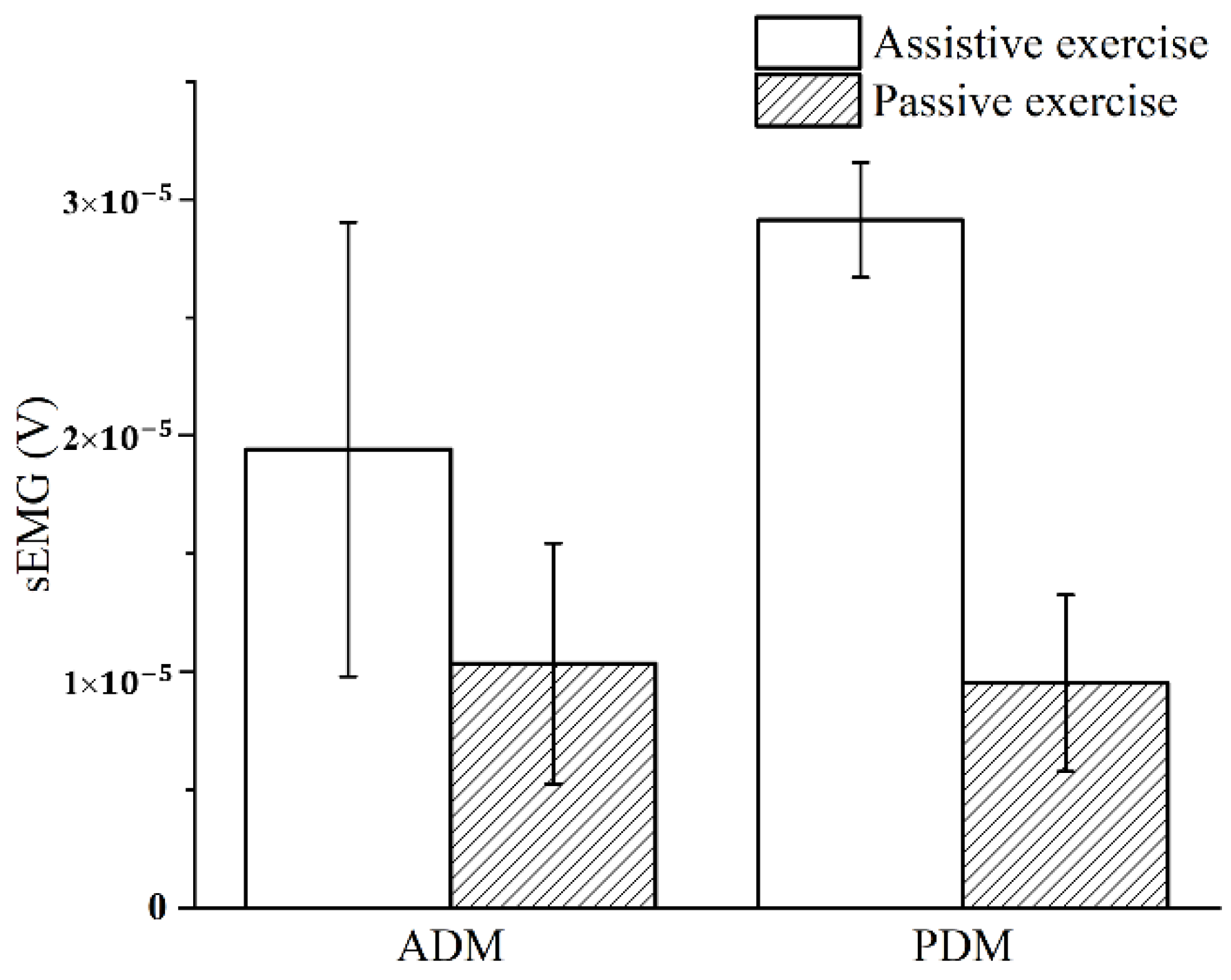
| Muscle | Assistive Exercise (×10−5 V) | Passive Exercise (×10−5 V) | p |
|---|---|---|---|
| ADM | 1.941 ± 0.962 | 1.034 ± 0.509 | 0.019 |
| PDM | 2.914 ± 0.243 | 0.952 ± 0.374 | 0.001 |
Publisher’s Note: MDPI stays neutral with regard to jurisdictional claims in published maps and institutional affiliations. |
© 2022 by the authors. Licensee MDPI, Basel, Switzerland. This article is an open access article distributed under the terms and conditions of the Creative Commons Attribution (CC BY) license (https://creativecommons.org/licenses/by/4.0/).
Share and Cite
Feng, G.; Zhang, J.; Zuo, G.; Li, M.; Jiang, D.; Yang, L. Dual-Modal Hybrid Control for an Upper-Limb Rehabilitation Robot. Machines 2022, 10, 324. https://doi.org/10.3390/machines10050324
Feng G, Zhang J, Zuo G, Li M, Jiang D, Yang L. Dual-Modal Hybrid Control for an Upper-Limb Rehabilitation Robot. Machines. 2022; 10(5):324. https://doi.org/10.3390/machines10050324
Chicago/Turabian StyleFeng, Guang, Jiaji Zhang, Guokun Zuo, Maoqin Li, Dexin Jiang, and Lei Yang. 2022. "Dual-Modal Hybrid Control for an Upper-Limb Rehabilitation Robot" Machines 10, no. 5: 324. https://doi.org/10.3390/machines10050324
APA StyleFeng, G., Zhang, J., Zuo, G., Li, M., Jiang, D., & Yang, L. (2022). Dual-Modal Hybrid Control for an Upper-Limb Rehabilitation Robot. Machines, 10(5), 324. https://doi.org/10.3390/machines10050324