1. Introduction
The Hy-Vo chain is also called the rocker-pin jointed silent chain [
1]. On one hand, by replacing the rotation pin with a rocker pin, the Hy-Vo chain can suffer greater torsion and have a longer life [
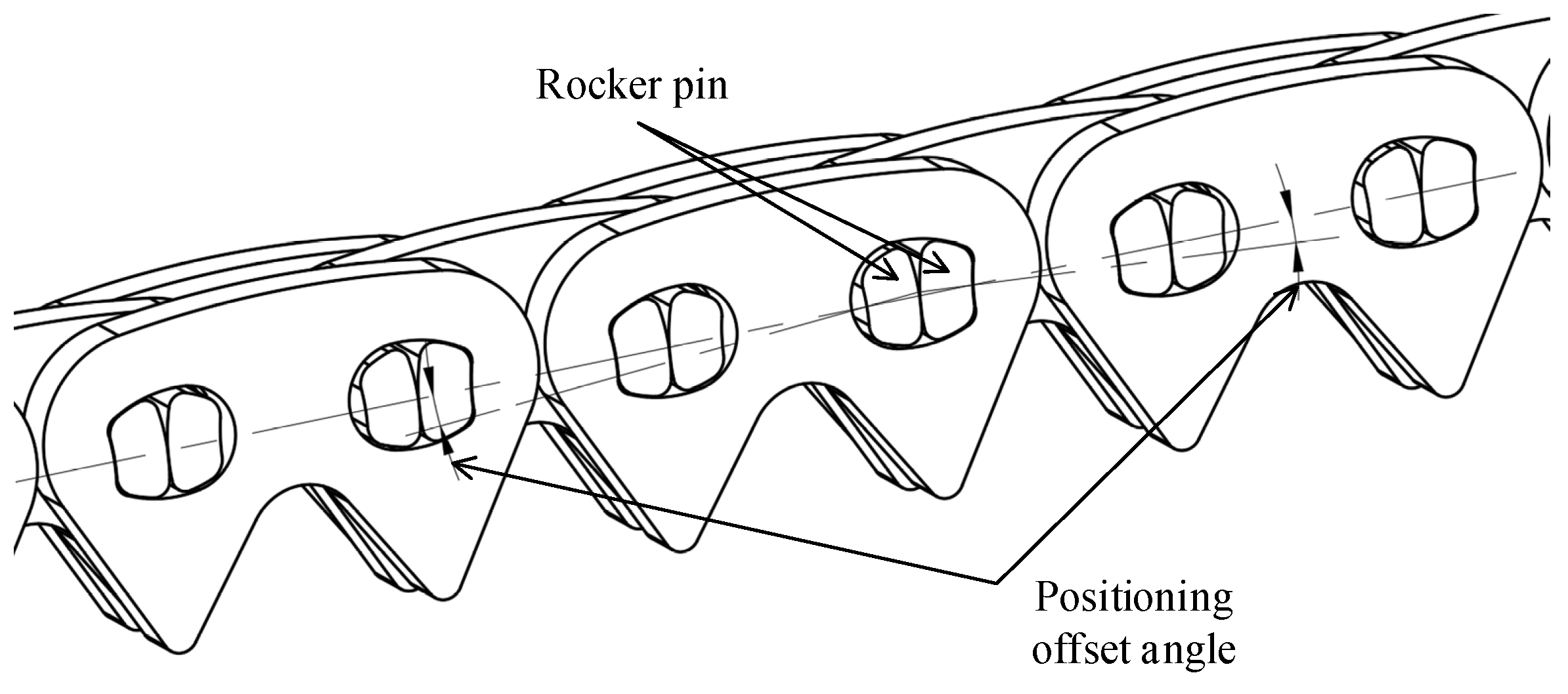
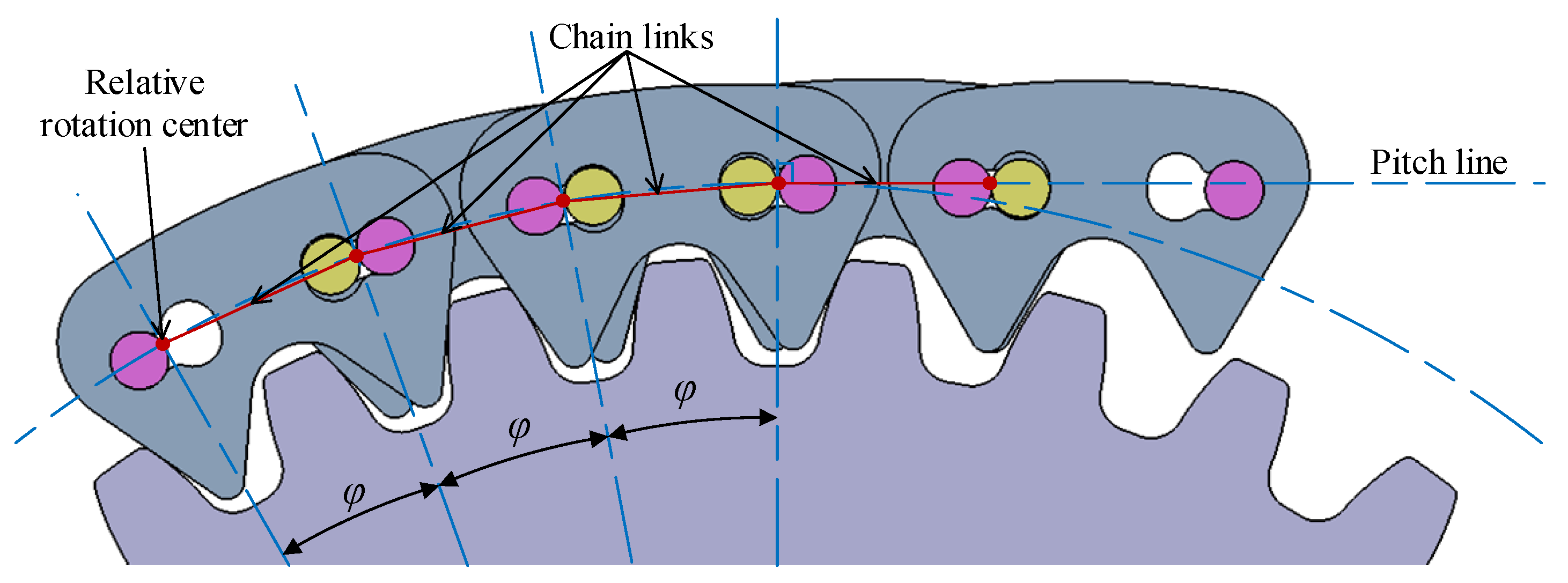
2]. On the other hand, the Hy-Vo chain has a smaller polygonal action that means a better transmission performance. The polygonal action is a kind of inherent property for a chain drive because the track of the instantaneous velocity center between the sprocket and the chain is a polygon rather than a circle; thus, the fluctuations for the chain and driven sprocket will be caused. For the normal chain, the polygonal action can be reduced effectively only by increasing the tooth number of the sprocket. For the Hy-Vo chain, there is another way to reduce the polygonal action. As shown in
Figure 1, by offsetting a little angle to the position of the rocker pin, the equivalent pitch can be variated when there is a relative rotation between any two chain plates; thus, the track of the instantaneous velocity center will close to a circle, and the polygonal action can be reduced [
3,
4]. However, the variable pitch characteristic of the classical Hy-Vo chain cannot fully satisfy the requirements for minimizing the system’s polygonal action. To minimize the polygonal action as much as possible, the equivalent pitch should be increased with the increase in the rotation or meshing angle [
5,
6]. However, for the classical Hy-Vo chain, with the increase in the rotation or meshing angle, the equivalent pitch is first increased then decreased [
7,
8]. Therefore, the transmission performance cannot be further enhanced under the existing Hy-Vo chain design systems.
The special-shaped design of the rocker pin is another disadvantage for the existing Hy-Vo chain design systems. Owing to the special-shaped design of the rocker pin, the chain plate hole has to be designed in a special-shaped way [
9]. Firstly, the special-shaped rocker pin and hole represent a complex manufacturing process and an expensive manufacturing cost, which will obviously restrict the large-scale applications of the Hy-Vo chain. Secondly, due to the special-shaped design method, there is no guarantee that the profile of the rocker pin can match with the profile of the chain plate hole; thus, the abnormal stress concentration on the positioning contact may be increased, and the chain life may be decreased [
10]. Thirdly, the collision probability between the special-shaped rocker pin and the special-shaped chain plate hole is increased further [
11]. To reduce the unexpected collisions, the special-shaped structure of the rocker pin and hole is becoming more complex. Although a series of a new type of Hy-Vo chain products with excellent performance has been innovated, such as the round-shape hole Hy-Vo chain, the kidney-shape hole Hy-Vo chain (
Figure 1), the heart-shape hole Hy-Vo chain, and the rhombus-shape hole Hy-Vo chain, the basic problems for the Hy-Vo chain special-shaped design method are still not solved. Consequently, it is necessary to solve the special-shaped structural problem for the Hy-Vo chain plate hole and rocker pin.
Over the years, numerous scholars have devoted themselves to innovating more silent chain products with better transmission performance. Bucknor, N.K., et al. [
12], based on the kinematic and static theory of the general silent chain, further analyzed the meshing between the rocker-pin jointed silent chain plate and the involute sprocket. Meng, F.Z., et al. [
13,
14,
15] established the chain-sprocket-cutter meshing system, raised the meshing theory and proper design for the chain plate and sprocket, studied the key design method for the chain plate hole and rolling pin for the Hy-Vo chain, and proposed a new type of Hy-Vo chain with the heart-shaped hole. Xue, Y.N., et al. [
16,
17] researched a kind of new type of dual-meshing silent chain transmission system and the relative meshing theory and modified the tooth profile of a silent chain to decrease the meshing friction. Cheng, Y.B., et al. [
18,
19,
20,
21] researched the multi-variation of a rocker-pin silent chain in a dual-phase drive system, designed a rocker-pin silent chain as a timing system for some kinds of engine, and proposed a double-side meshing silent chain drive. Liu, X.L., et al. [
22] designed a low-noise, double-pitch silent chain for a conveyor and verified the correctness of the design method by analysis and testing. Zhang, M.Y., et al. [
23], from the perspective of the thermal EHL, investigated the plate-pin hinge pairs of a silent chain by using a narrow finite line contact. Pan, M., et al. [
24] modified the design of the silent chain drive system to reduce the annoying noise. However, there is no research to study the effect of the ultra-small rolling radius on the meshing system of the Hy-Vo chain.
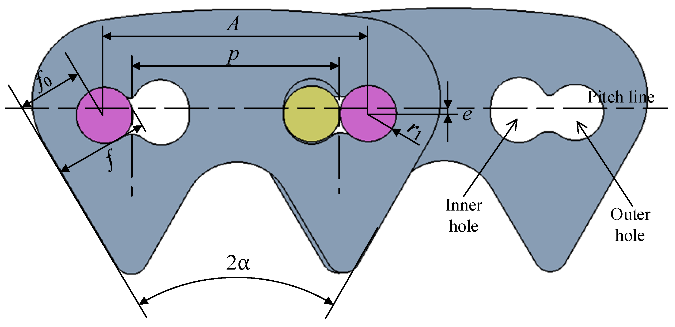
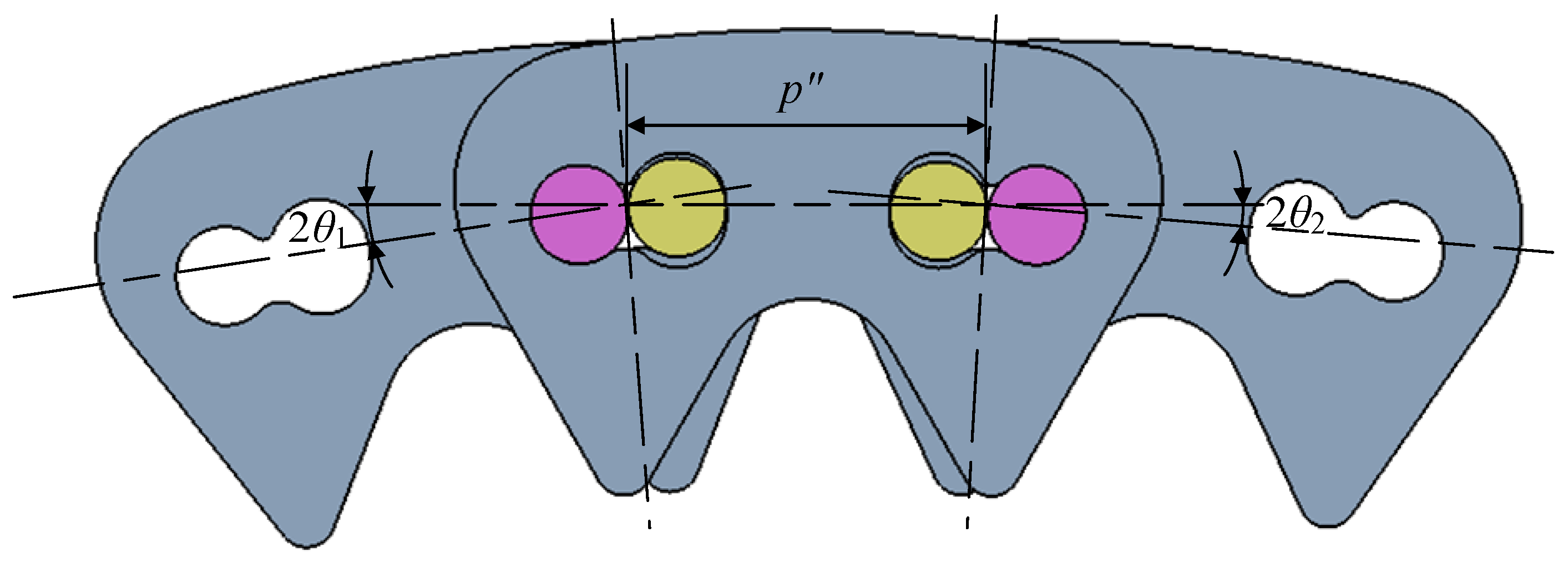
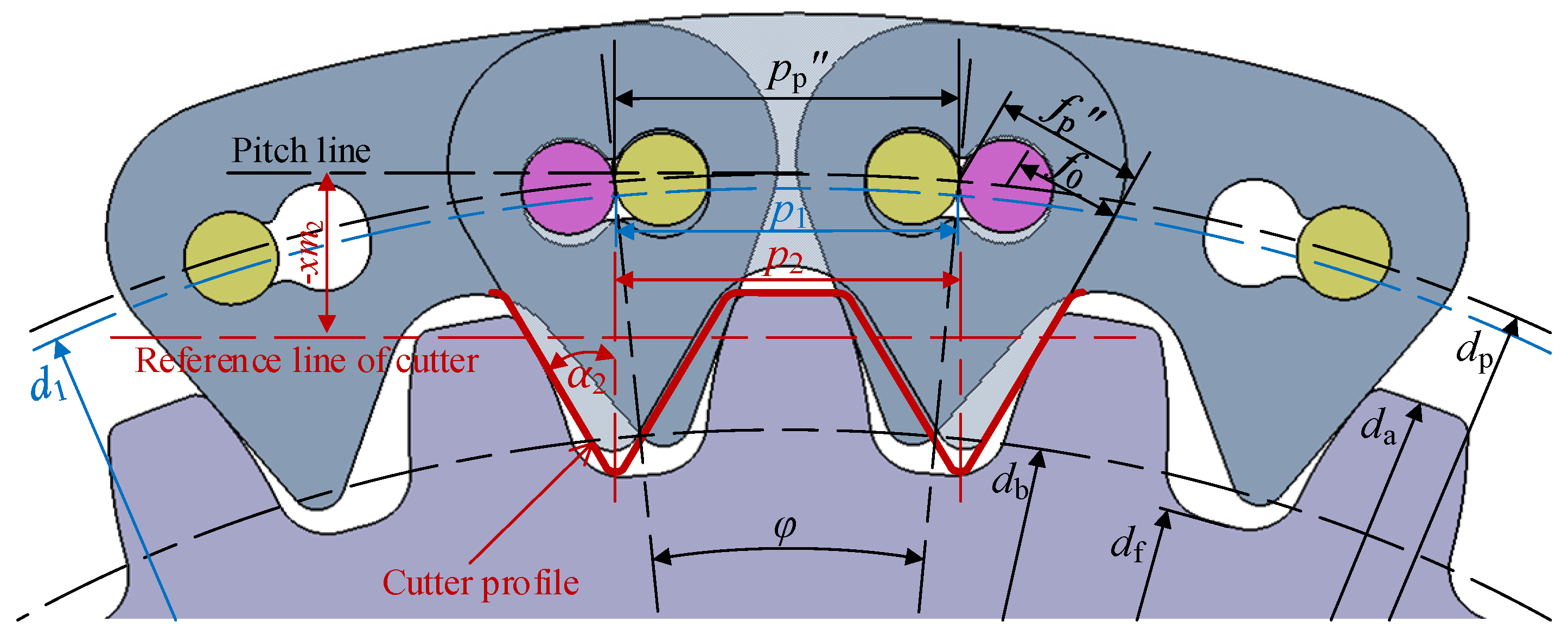
In a way which is different from the existing design systems, the special-shaped rocker pin is replaced with the round-shaped rocker pin for the new Hy-Vo chain proposed in this paper; through offsetting the location of the rocker pin center from the pitch line, the variable pitch design can be achieved. According to the rolling theory of the rocker pin, the chain-sprocket-cutter meshing design system of the new Hy-Vo chain is established, and the positive relation between the equivalent pitch and the rotation or meshing angle is proved. Based on the analysis model of polygonal action, by calculating a specific example, it is proved that the variable pitch characteristic of the new Hy-Vo chain is controllable. Via a comparative analysis of the system center distance fluctuations for the new and the classical Hy-Vo chain, both the system fluctuation difference and the system running deviation are smaller for the new Hy-Vo chain. With the analysis of the MFBD, the stress distribution of the chain plate and the rocker pin is more uniform for the new Hy-Vo chain, and the fatigue life is longer. The study results show that, compared with the classical Hy-Vo chain, the new Hy-Vo chain with the ultra-small rolling radius has better meshing performance and fatigue resistance, as well as better process economy. Moreover, the new design proposed in this paper is not only a novel structure for the Hy-Vo chain drive, but also reveals the meshing mechanism and the controllable variable pitch characteristic.
4. Variable Pitch Characteristic
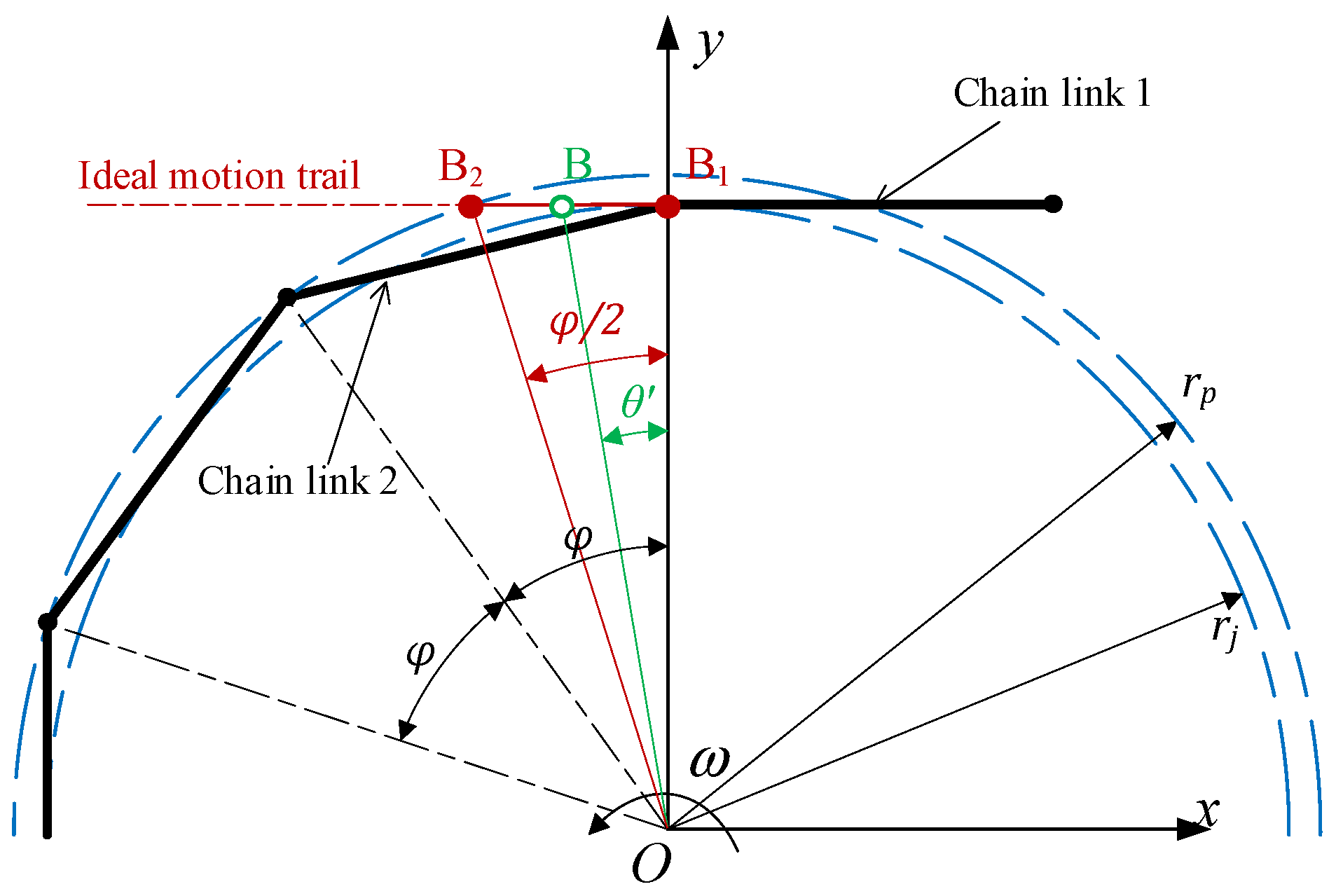
To conveniently analyze the influence of the variable pitch characteristic of the new Hy-Vo chain on the meshing, the meshing system model can be simplified as a polygonal action model, as
Figure 5 shows. In the simplification process, the chain plate can be expressed as a line segment that is called the chain link, and the relative rotation center of chain can be represented as a point; thus, the meshing between the chain and the sprocket can be expressed as a polygon, of which the edge number is equal to the tooth number
z.
4.1. Boundary Conditions
Figure 6 shows a kind of model to roughly estimate the polygonal action of the Hy-Vo chain, and this model represents the relation between the variable pitch characteristic and the meshing angle, rather than the specific position of the chain plates in the meshing process [
25,
26,
27]. In
Figure 6,
S(
xOy) is the absolute coordinate system, and the rotation center of the sprocket is in the origin
O. The rotation direction of the sprocket is anticlockwise, the rotation velocity is
ω, and the rotation angle is
θ′. B represents the relative rotation center between chain link 1 and chain link 2 in the meshing process. B
1 represents the initial position of the relative rotation center B at the beginning of the meshing, and B
2 is the ultimate position of B at the end of the meshing.
The distance between B
1 and
O can be roughly equal to the radius of the pitch circle
rj:
The distance between B
2 and
O can be equal to the radius of the positioning circle
rp″:
We can know from
Figure 6 that there will be no polygonal action in the meshing if the motion trail of the relative rotation center B is a horizontal line. Based on Equations (12) and (13), the boundary condition is:
Substituting Equations (12) and (13) into Equation (14), we can obtain:
The system polygonal action will be decreased extremely when Equation (15) can be satisfied. Supposing that the ideal equivalent positioning pitch is
Pp0″, based on Equation (15), there is:
If the absolute value of the deviation between the actual equivalent positioning pitch
Pp” and the ideal equivalent positioning pitch
Pp0″ is
δp, there is:
In Equation (17), δp is smaller and the polygonal action of the meshing system of the Hy-Vo chain is smaller. If there is δp = 0 in the system, the polygonal action can be roughly regarded as zero.
4.2. System Analysis
Supposing that there are two sprockets in the transmission system, the tooth number of the drive sprocket is
z1, the tooth number of the driven sprocket is
z2, and there is
z1 <
z2. According to Equation (16), we can obtain the ideal equivalent positioning pitch based on the drive sprocket:
where
φ1 is the pitch angle of the drive sprocket, and there is
φ1 = 2π/
z1.
Similarly, the ideal equivalent positioning pitch based on the driven sprocket is:
where
φ2 is the pitch angle of the driven sprocket, and there is
φ2 = 2π/
z2.
Because z1 < z2, there is pp01″ > pp02″.
Let the pitch deviation
δp1 based on the drive sprocket be zero; we can obtain:
Based on Equation (20) and the equations in
Table 1, we can obtain:
If the pitch deviation based on the driven sprocket is
δp2, according to Equations (5) and (18)–(21), there is:
As for this transmission system, based on the conclusion of 4.1, because δp1 = 0, δp2 is smaller and the system polygonal action is smaller.
Supposing
δ12 =
pp01″ −
pp02″ to be the reference value, according to Equations (18) and (19), there is:
If p, z1, and z2 are constants, based on Equation (15), δ12 is a constant too, and there is δ12 > 0.
Making
δp2 minus
δ12, there is:
According to Equation (20), there is
pp1″ =
pp01″; thus, we can further solve Equation (24):
Supposing that the function form of Equation (25) of the rolling radius of the rocker pin
r1 is:
Plugging Equations (1) and (5) into Equation (26), the solution of
f(
r1) = 0 is:
where
k is a constant that should satisfy:
In Equation (27), r10 is the boundary value of r1 when δp2 = δ12.
The derivation of Equation (26) is:
Because z1 < z2, there is φ1 > φ2; based on Equation (29), we can obtain f ′(r1) > 0. Therefore, f(r1) is a monotonic increasing function of r1. Thus, r1 is smaller and δp2 is smaller.
Based on Equation (27), when
r1 <
r10, there is:
Therefore, as for the new Hy-Vo chain with the ultra-small rolling radius, the rolling radius of the rocker pin is smaller and the system polygonal action is smaller.
It should be pointed out that this characteristic did not exist in the classical Hy-Vo chain. Based on the former research about the classical Hy-Vo chain, there is
pp1″ <
pp2″ when
z1 <
z2 [
5,
7,
9]. According to Equation (25), for the classical Hy-Vo chain, there will always be:
Comparing with Equations (30) and (31), we can obtain the conclusion that the polygonal action of the meshing system of the new Hy-Vo chain is smaller than that of the classical one when making the rolling radius of the rocker pin r1 smaller than r10. Moreover, the rolling radius r1 is smaller and the system polygonal action is smaller. Therefore, we state that the variable pitch characteristic of the new Hy-Vo chain is controllable.
4.3. Calculation
In this paper, a common example is used to verify the meshing performance of the new Hy-Vo chain. In this example, the standard pitch
p is equal to 9.525 mm, the tooth number of the drive sprocket
z1 is 35, and the tooth number of the driven sprocket
z2 is 37 [
4,
11,
21].
According to the equations in
Table 1, there are
φ1 = 0.1795 and
φ2 = 0.1698. Based on Equation (18), we can obtain
pp1″ =
pp01″ = 9.563499 mm. Substituting
φ1 and
φ2 into Equation (28), we can obtain
k = 11.464849. Plugging
k into Equation (27), we can obtain
r10 = 5.0548 mm. Therefore, we can know that the meshing performance of the transmission system will be further improved by using the new Hy-Vo chain with the ultra-small rolling radius if
r1 <
r10 = 5.0548 mm.
Based on Equation (21),
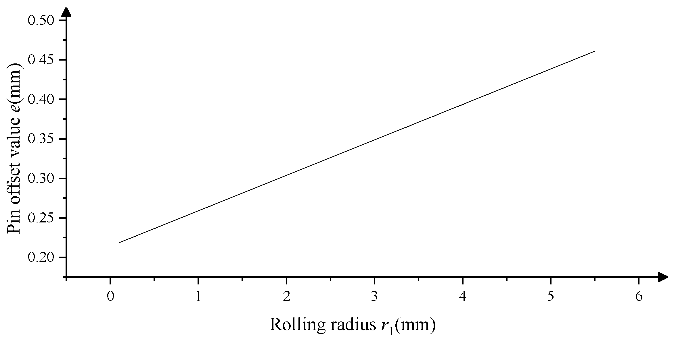
Figure 7 shows the calculation results about the pin offset value
e under different rolling radii
r1. It can be seen from
Figure 7 that the relation between
e and
r1 is strictly linear. Furthermore, based on the calculation results about
e,
δp2, and
δ12 under different rolling radii
r1 can be calculated by Equations (1), (5), (22) and (23), and the relative values are shown in
Figure 8.
Firstly, as we can see from
Figure 8,
δp2 is increased with the increase of
r1, and
δ12 is a constant and always equal to 0.00406 mm. Therefore, the assumptions in
Section 4.2 are verified. Secondly, as for this example, the rolling radius of the rocker pin
r1 cannot be greater than 5.055 mm and even cannot be greater than 1.6 mm because such a great value of
r1 means that the chain plate hole will be too big to reduce the strength of the chain plate. In
Figure 8, the blue area means the possible value range for the rolling radius
r1; so, the condition
r1 <
r10 = 5.0548 mm for this example is proved to be unconditionally true. Commonly, the rolling radius of the classical Hy-Vo chain in this example is 7.4 mm, which is obviously greater than the value of
r10. Furthermore, we can guess, the meshing performance of the new Hy-Vo chain will be better than that of the classical Hy-Vo chain no matter how big
r1 is.
5. Fluctuation Analysis
Normally, the meshing performance of the chain transmission system can be tested by the center distance fluctuation difference; the system fluctuation difference is smaller, and the meshing performance of the system is greater [
28]. The multi-body dynamics model of the testing system is shown in
Figure 9 [
29,
30]; the rotation center of the drive sprocket
O1 is fixed in the origin of the absolute coordinate system
S(
xOy), the rotation center of the driven sprocket
O2 is on the
x-axis, and the distance between
O1 and
O2 is
Sd. If an outward force
F is acting on the driven sprocket,
O2 will fluctuate on the x-axis as the drive sprocket is rotating. In engineering, the fluctuations of
O2 can be regarded as the system fluctuations. Supposing that the maximum value of
Sd is
Sdmax, and the minimum value of
Sd is
Sdmin, the system fluctuation difference Δ
s will be
Furthermore, in engineering, the center distance fluctuation differences to test the system meshing performance are mainly obtained by multi-body dynamics simulations rather than real experiments. On one hand, in a way different from the meshing of gears, in the actual running, the assembly error and the manufacturing error from each chain plate and pin will accumulate in the system by meshing. Thus, the value of the actual system fluctuation difference will be much larger than the theoretical one. As a result, the real influential factors of the chain meshing will be hidden. On the other hand, the system center distance is also affected by the system wear, and the center distance will be increased with the increase in running time. Therefore, the system center distance fluctuations obtained by the real experiments are always used to estimate the chain reliability rather than the system meshing performance.
In this paper, the multi-body dynamics model of the testing system is simulated by CAE software RecurDyn. In RecurDyn, if the contact surfaces are both convex, the contact can be computed by the
SolidContact algorithm. Otherwise, the contact can be computed by the
GeoSurfaceContact algorithm. As
Figure 9 shows, the contact between the chain plate and the sprocket belongs to the convex-convex contact; thus, these contacts are computed by the
SolidContact algorithm. The contact between the chain plate and the rocker pin does not belong to the convex-convex contact; thus, these contacts are computed by the
GeoSurfaceContact algorithm. For these contacts, the stiffness coefficient is 100,000, and the damping coefficient is 10. Because the contacts in the chain transmission are almost nonlinear, the integrator type of solver is selected as IMGALPHA, and the other parameters are left at the default settings.
5.1. Groups Setting
Based on the calculation and analysis results from the example in
Section 4.3, there are eight testing groups in the simulation. In these groups, groups 1 to 7 represent the new Hy-Vo chain with different rolling radii, the control group represents the classical Hy-Vo chain, which is with the optimal parameter values, and the outer profile of the chain plate in each group is exactly the same. In this paper, the classical Hy-Vo chain is the Hy-Vo chain based on the kidney-shape hole, as shown in
Figure 1. On one hand, for the existing design system, there is no difference in the rolling radius of the rocker pin among all types of Hy-Vo chains. On the other hand, the kidney-shape hole Hy-Vo chain is widely applied in engineering and has a better stability and meshing performance [
9]. Therefore, the Hy-Vo chain based on the kidney-shape hole can properly represent the classical Hy-Vo chain.
Supposing that the rotation direction of the drive sprocket is anticlockwise, the rotation velocity of the drive sprocket
ω is 2000 rpm, the preloading force
F is 150 N, the initial system center distance is
Sd0 = 219.056 mm, and the chain plate number is 82 [
4,
11,
21]. The values of the main parameters for these groups are listed in
Table 2. It should be pointed out that there is no pin offset value
e for the classical Hy-Vo chain, and the similar parameter is the pin positioning offset angle
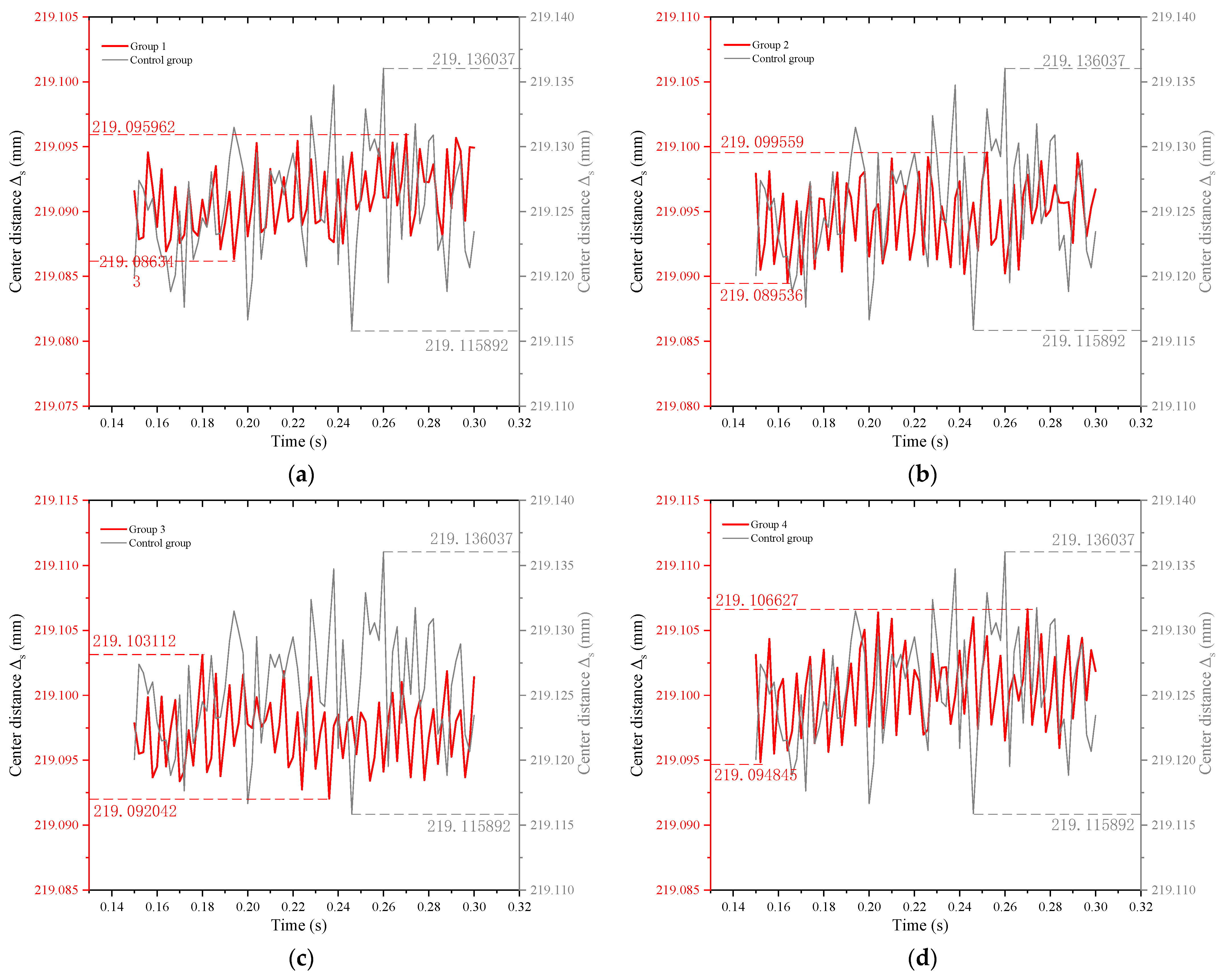
γ. If the computational time is 0.3 s, the step is 150, the simulation results of the center distance fluctuations are shown in
Figure 10.
5.2. Fluctuation Difference
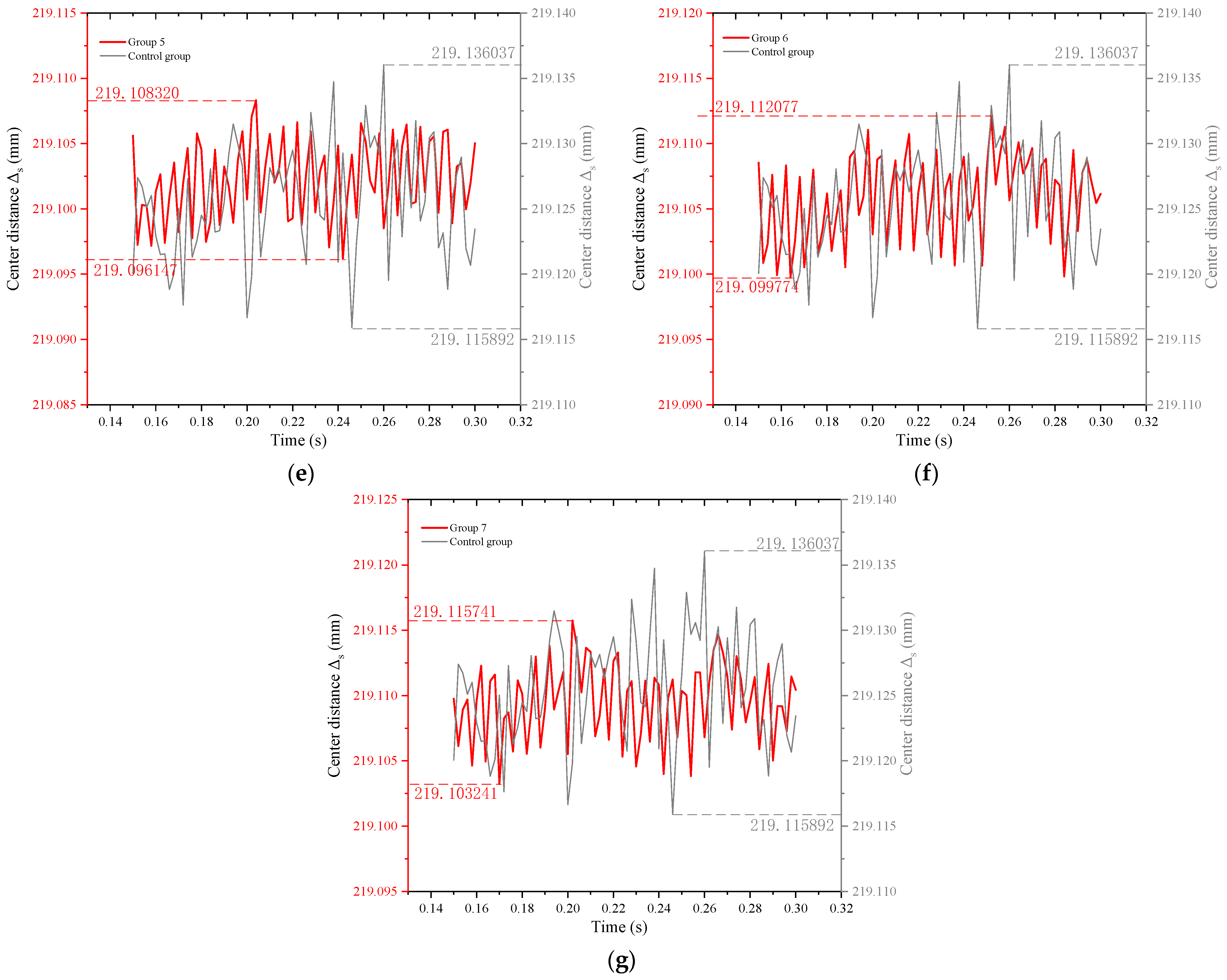
Figure 10a–g represent the comparison of the center distance fluctuations between the new Hy-Vo chain and the classical Hy-Vo chain in groups 1 to 7, respectively. It can be seen from
Figure 10 that the center distance fluctuation differences of the new Hy-Vo chain are all smaller than that of the classical one. Therefore, the meshing performance of the new Hy-Vo chain is much better than that of the classical Hy-Vo chain. For the classical Hy-Vo chain, there are
Sdmax = 219.136037 mm and
Sdmin = 219.115892 mm; based on Equation (32), we can obtain the fluctuation difference, which is Δ
s = 0.020145 mm. Similarly, for the new Hy-Vo chain, the fluctuation differences under the different rolling radii can be obtained, as
Figure 11 demonstrates.
We can obtain a conclusion from
Figure 11; for the new Hy-Vo chain, the rolling radius of rocker pin
r1 is smaller, the system fluctuation difference is smaller, and the system meshing performance is better. Combining with
Figure 8, the linear relation between the rolling radius of the rocker pin and the system meshing performance can be roughly verified; thus, the design and analysis methods for the new Hy-Vo chain proposed in this paper are proved to be reliable.
5.3. Mean Fluctuations
Furthermore, the value of the mean fluctuation of the center distance can also estimate the stability of the system; the system stability will be better if the value of the mean fluctuation is closer to the initial center distance. Based on
Figure 10, the value of the mean fluctuations for each group can be obtained easily. In these simulation results, the value of the mean fluctuations of the control group is 219.1256 mm, and the values of the mean fluctuations for groups 1 to 7 are shown in
Figure 12.
Supposing that the difference between the value of the mean fluctuations and the initial center distance is the system running deviation Δ
d, the meshing performance will be better if Δ
d is smaller. Taking the control group as an example, because the initial center distance is 219.056 mm, the running deviation is thus Δ
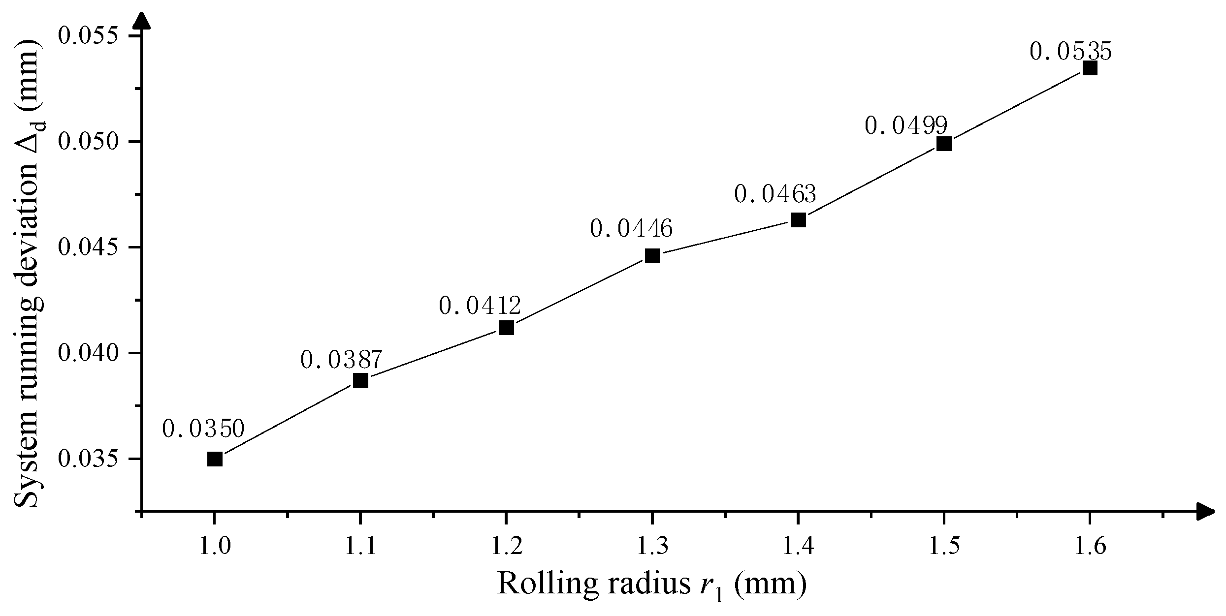
d = 219.1256 – 19.056 = 0.0696 mm. Similarly, the system running deviations under the different rolling radii for the new Hy-Vo chain can be obtained, as
Figure 13 shows. From
Figure 13, we can know: (1) for the new Hy-Vo chain, the system running deviation Δ
d will increase with the increase of rolling radius
r1; thus, the meshing performance will be improved with the decrease of
r1. (2) The values of the system running deviation of the new Hy-Vo chain are all smaller than that of the classical Hy-Vo chain; thus, the meshing performance of the new Hy-Vo chain will be better than that of the classical one, no matter what
r1 is. (3) The relation between the system running deviation Δ
d and the rolling radius
r1 is proved to be linear, and it can match with the analysis and calculation results in
Section 4.3.
6. Structure Analysis
By using MFBD (Multi Flexible Body Dynamic) in the software RecurDyn, the structural rationality of the Hy-Vo chain can be analyzed, and the MFBD model is displayed in
Figure 14. In
Figure 14, the rotation center of the sprocket is fixed in the origin of the absolute coordinate system
S(
xOyz); the rotation direction of the sprocket is anticlockwise;
ω is the rotation velocity of the sprocket;
F1 is the applied force on the system tensioning side;
F0 is the system preload; the form of chain is 1 × 2; and the thickness of chain plate is 2 mm. In this simulation,
F1 = 200 N,
F0 = 50 N,
ω = 2000 rpm; the velocity drive function of the sprocket is Step(time, 0, 0, 0.01, 66.7*pi); the computational time is 0.02 s; the step is 50, and the mesh type of the flexible body is Solid8(Hexa8) [
10]. It should be pointed out, when analyzing the chain plate, that only the target chain plate can be set as the flexible body. Similarly, when analyzing the rocker pin, only the target pin and the adjacent pin can be regarded as the flexible body. As for the flexible chain plate, the max element sides are 0.5, the min element sides are 0.2, and the gradation factor is 2. As for the flexible rocker pin, the max element sides are 0.138, the min element sides are 0.138, and the gradation factor is 2. According to the groups setting in
Table 2, we use group 3 to represent the new Hy-Vo chain and use the control group to represent the classical Hy-Vo chain.
It should be pointed out that the SolidContact algorithm cannot be used to compute the contact between the rigid body and the flexible body. Therefore, the contact between the flexible chain plate and the rigid sprocket can only be computed by the GeoSurfaceContact algorithm. In the MFBD simulation, the integrator type of solver is selected as HYBRID, and the other parameters are left at the default settings.
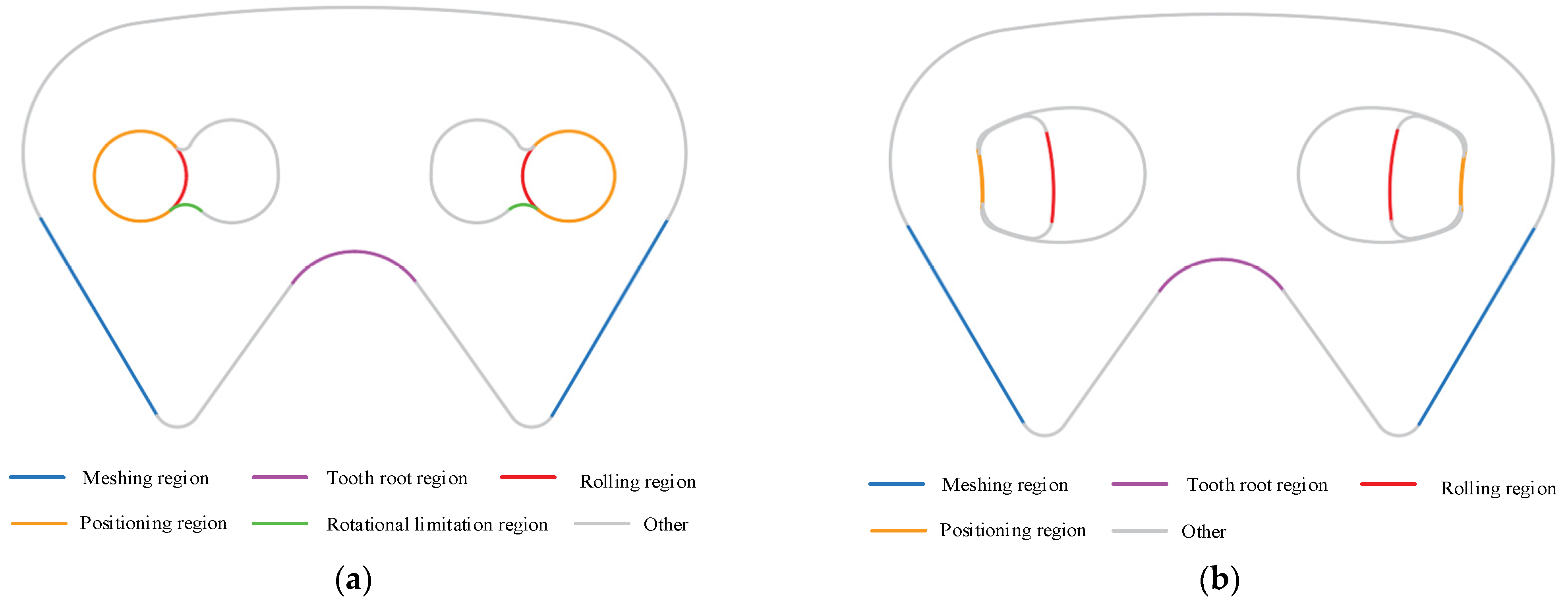
To conveniently describe the stress distribution, it is necessary to name the main stress region of the chain plate and the rocker pin for the Hy-Vo chain, as
Figure 15 shows.
6.1. Rocker Pin Analysis
6.1.1. Maximum Stress State
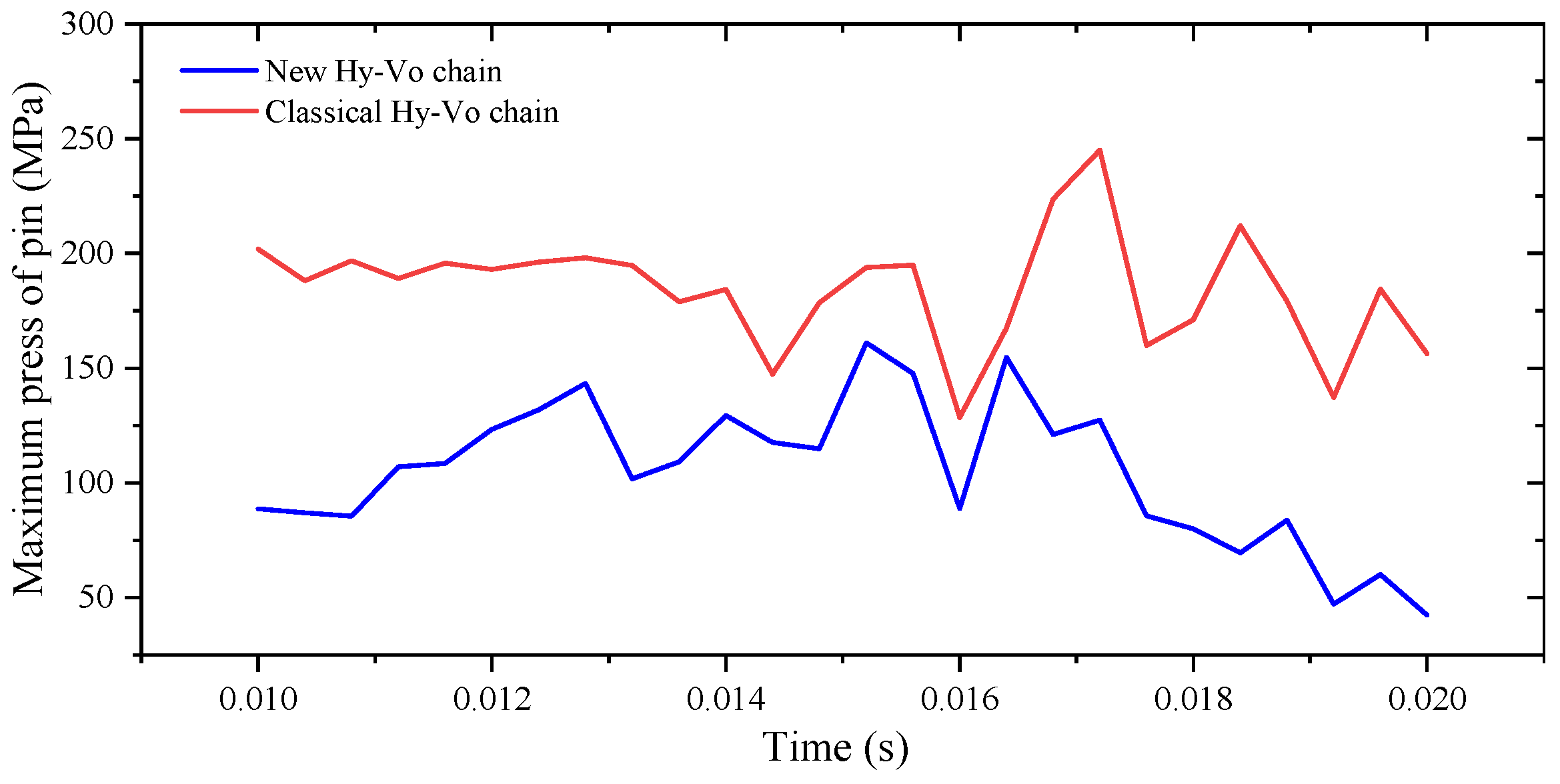
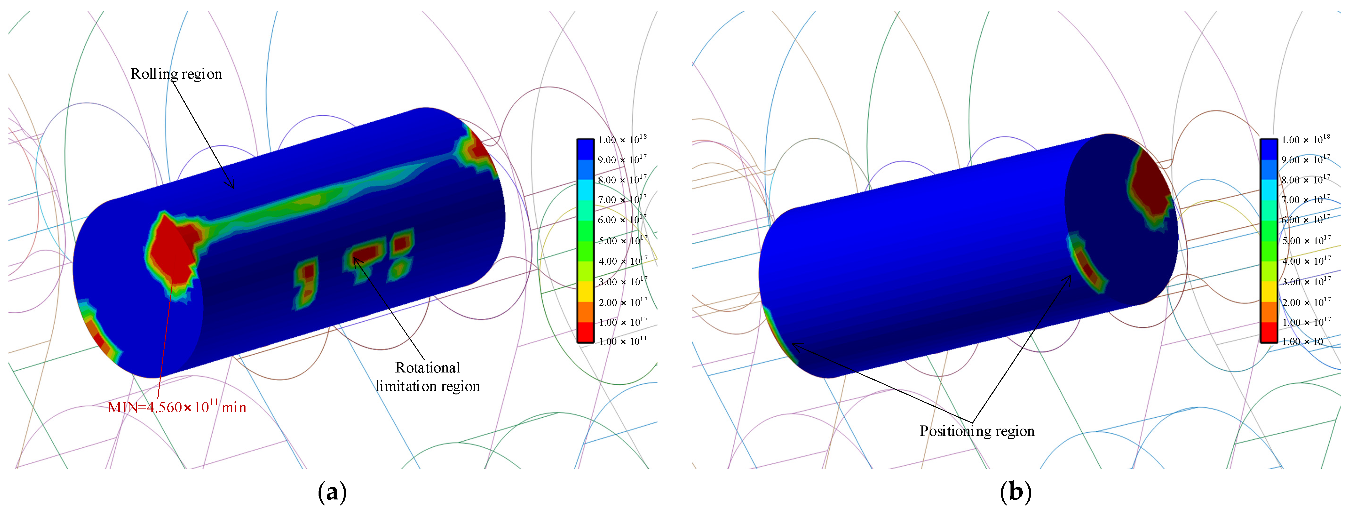
Figure 16 illustrates the maximum stress state for the rocker pin of the new Hy-Vo chain, and there are two relative stress concentration areas. The first stress concentration area is on the rolling region; in
Figure 16a, the rolling stress is mainly concentrated in the contact area between the two adjacent pins, but the stress can be evenly distributed along the length of the rocker pin. The second stress concentration area is on the rotational limitation region; in this region, the stress concentration is distributed abnormally to cause the maximum stress, and the value is 162.026855 Mpa. On the other hand, we can also know from
Figure 16b that the stress distribution on the positioning region of the rocker pin is relative uniform. If the material of the rocker pin is 38CrMoAl, so that the yield stress is 835 Mpa, because 162.026855 Mpa << 835 Mpa, the structure of the rocker pin of the new Hy-Vo chain can satisfy the design requirements.
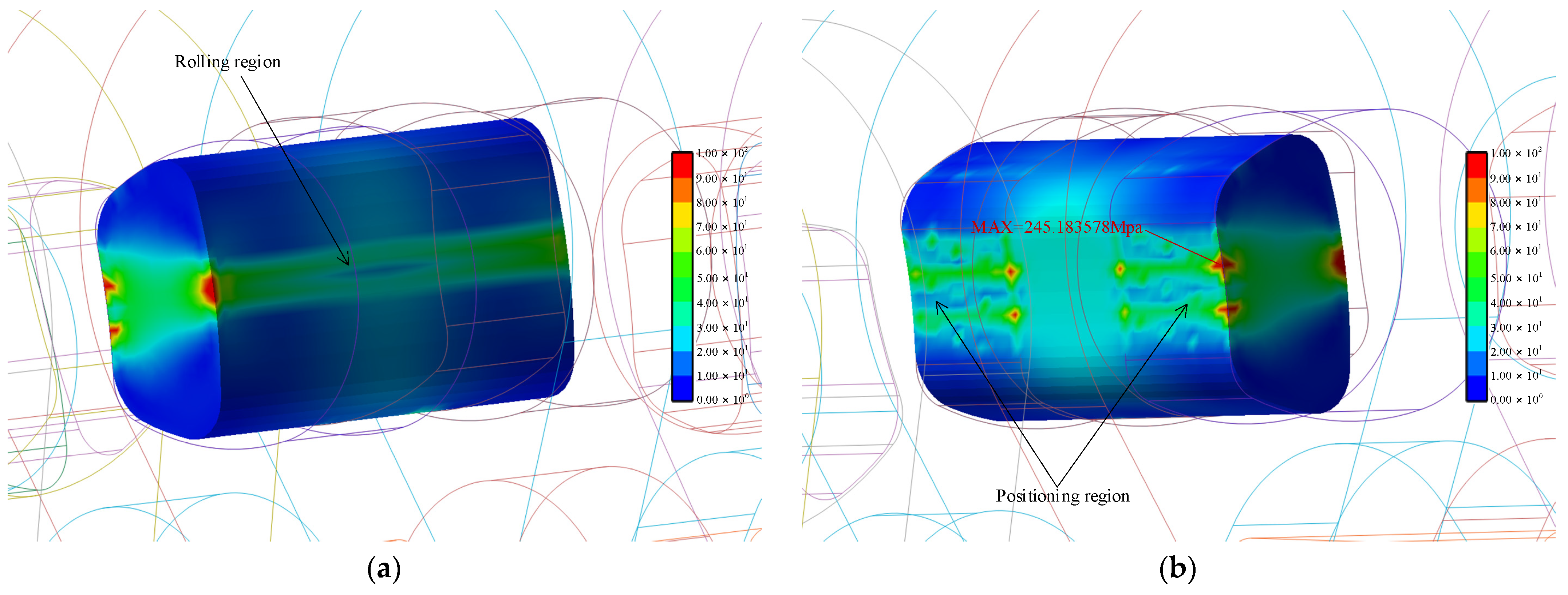
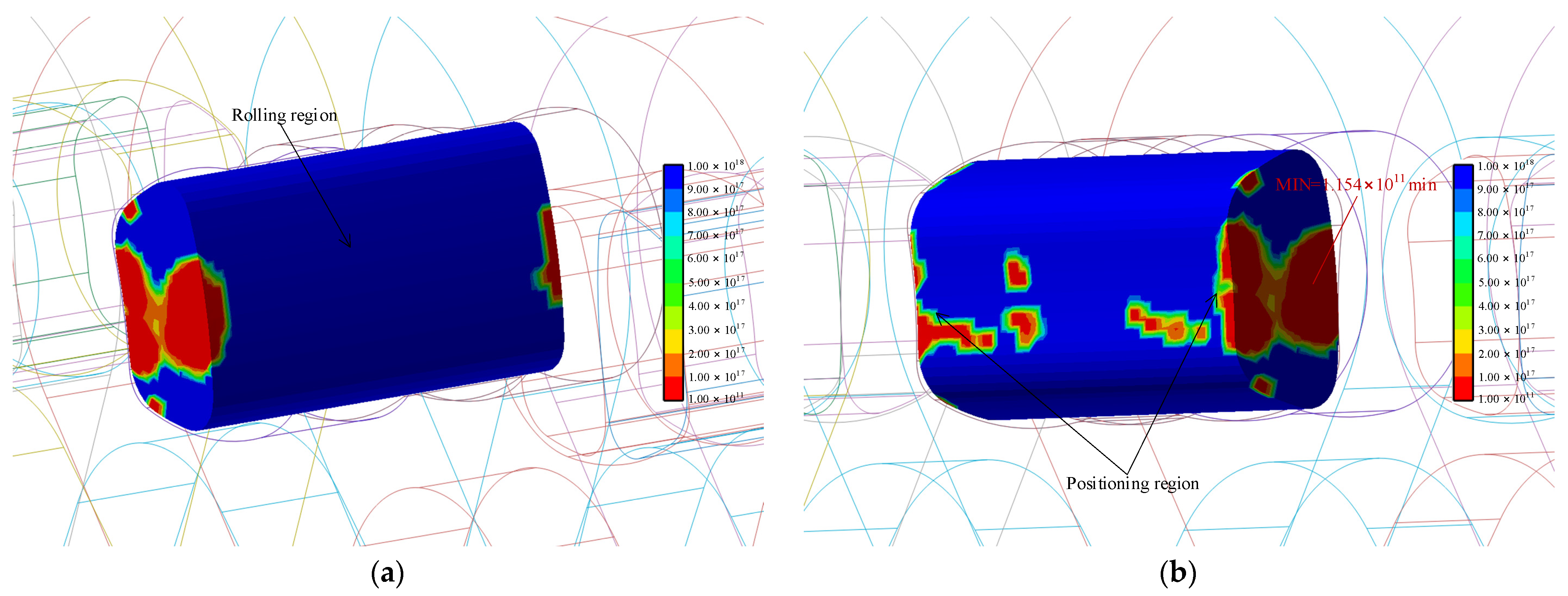
Figure 17 represents the maximum stress state for the rocker pin of the classical Hy-Vo chain. Firstly, there is a stress concentration area on the rolling region which is different from the new Hy-Vo chain; the rolling stress cannot be evenly distributed along the length of rocker pin; thus, two small areas of abnormal stress concentration are caused on both ends of rocker pin. Secondly, in a way which is also different from the new Hy-Vo chain, there are eight small areas of abnormal stress concentration in the intersection between the positioning region and the front or back surface of the chain plate. Thirdly, the maximum stress exists in one of ten areas of abnormal stress concentration, and the maximum stress is 245.183578 MPa. Because these abnormal stress concentration areas are all close to the pitch line or the pitch circle, the degree of stress concentration of the rocker pin of the classical Hy-Vo chain will be much greater than that of the new Hy-Vo chain. Furthermore, the maximum stress of the rocker pin of the classical Hy-Vo chain is 245.183578 MPa; on one hand, it is still much smaller than the yield stress of the material of the rocker pin; on the other hand, it is significantly greater than the maximum stress of the rocker pin of the new Hy-Vo chain.
Figure 18 shows the relation between the maximum stress of the rocker pin and the running time. From
Figure 18, we can know that the maximum stress of the rocker pin of the new Hy-Vo chain is smaller than that of the normal Hy-Vo chain at any time. Therefore, from the perspective of maximum stress, the structure of the rocker pin of the new Hy-Vo chain is better than that of the classical one.
6.1.2. Fatigue Analysis
Through using the Brown–Miller algorithm in the software RecurDyn, based on life analysis, we can obtain the fatigue contours of the rocker pin for the new Hy-Vo chain and the classical Hy-Vo chain, as
Figure 19 and
Figure 20 show. By comparing
Figure 19 and
Figure 20, we can know: (1) the fatigue areas for the rocker pin of the new Hy-Vo chain mostly exist on the rotational limitation region, the rolling region, and the end surfaces. For the classical Hy-Vo chain, the fatigue areas mainly exist on the positioning area and the end surfaces. (2) The fatigue area of the rocker pin of the new Hy-Vo chain is smaller than that of the classical Hy-Vo chain. (3) The minimum life of the rocker pin for the new Hy-Vo chain is 4.560 × 10
11 min, but that for classical Hy-Vo chain is 1.164 × 10
11 min; thus the rocker pin of the new Hy-Vo chain will have a longer life.
Through comparing the maximum stress and minimum fatigue life of the rocker pin for the new and the classical Hy-Vo chain, the results show that the structural design of the rocker pin of the new Hy-Vo chain is more reasonable.
6.2. Chain Plate Analysis
6.2.1. Maximum Stress State
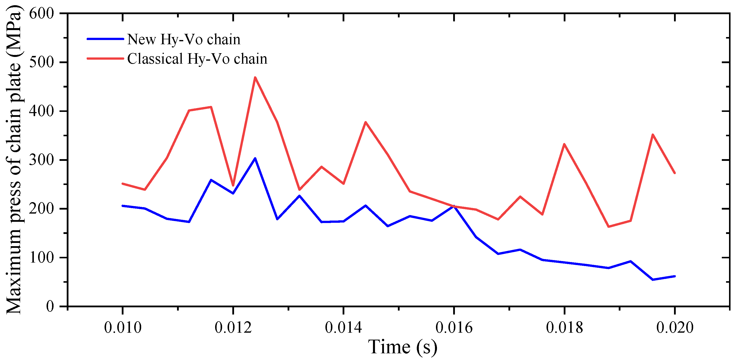
Figure 21 shows the comparison of the maximum stress state between the new Hy-Vo chain and the classical Hy-Vo chain. As for the new Hy-Vo chain plate, the stress distribution is relatively uniform; the maximum stress exists on the rotational limitation region, and the maximum stress is 303.126221 MPa. As for the classical Hy-Vo chain plate, the maximum stress exists on the positioning region, and the maximum stress is 468.663269 MPa. Obviously, for the new Hy-Vo chain, not only the value of the maximum stress is smaller, but also the dimension of the abnormal stress concentration area is smaller.
Figure 22 displays the relation between the maximum stress of the chain plate and the running time. It is easy to get that the maximum stress of the new Hy-Vo chain is smaller than that of the classical one at any time basically. Therefore, the stress distribution of new Hy-Vo chain plate is more uniform.
6.2.2. Meshing Analysis
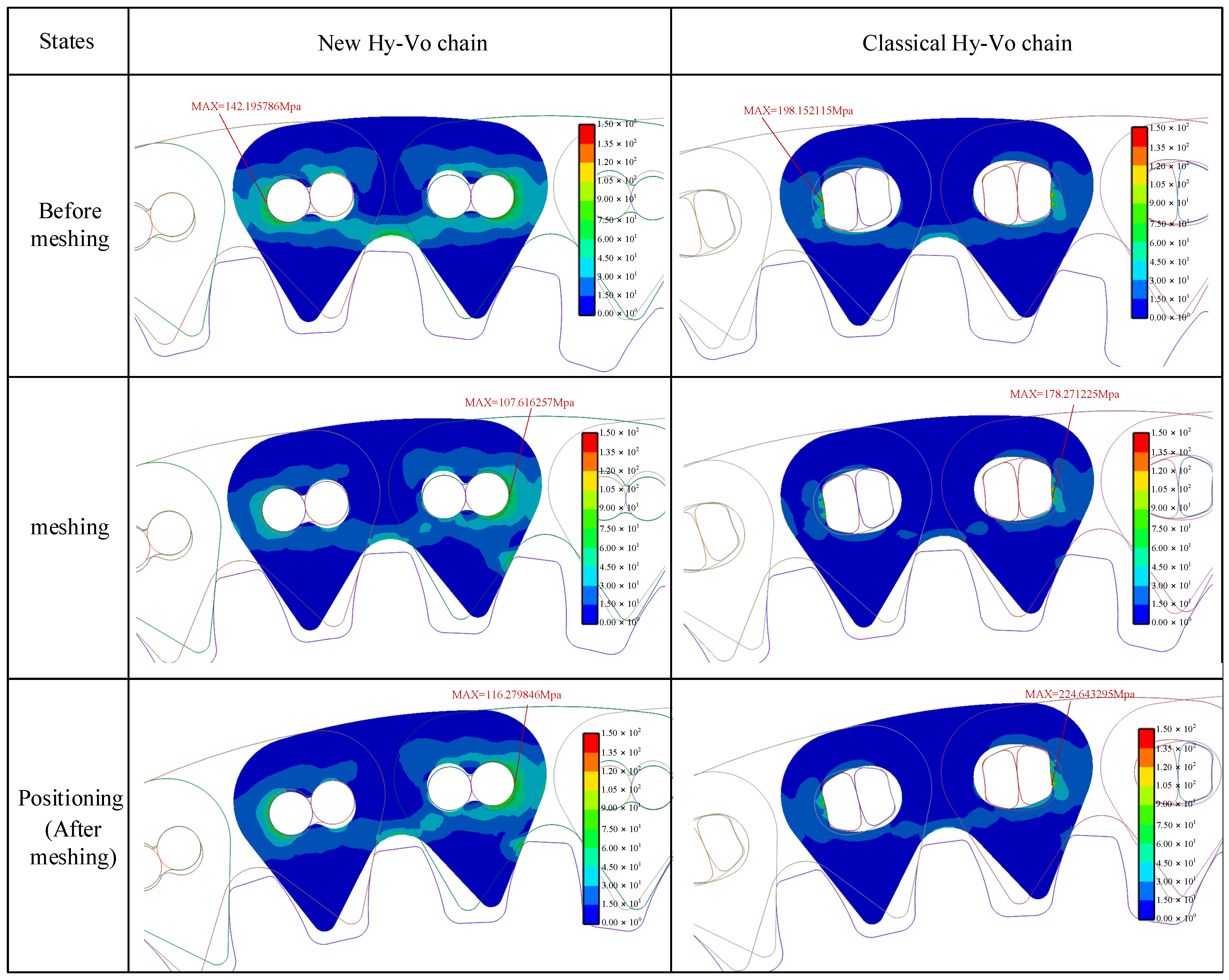
Figure 23 is the comparison of the stress analysis between the new Hy-Vo chain and the classical Hy-Vo chain when meshing. Under the action of the same tension force, the acreage of the stress distribution area of the new Hy-Vo chain plate is much more than that of the classical Hy-Vo chain plate. In addition, the value of the maximum stress of the new Hy-Vo chain plate is much smaller than that of the classical Hy-Vo chain plate. It means that the stress of the classical Hy-Vo chain plate is mainly concentrated on some small areas that are on the positioning region, rather than evenly distributed on the chain plate. However, in contrast, the stress on the meshing region of the new Hy-Vo chain plate is greater than that on the classical Hy-Vo chain plate.
6.2.3. Fatigue Analysis
Based on life analysis, we can obtain the chain plate fatigue contours for the new Hy-Vo chain and the classical Hy-Vo chain, as
Figure 24 displays. From the perspective of the fatigue area dimension, the dimension of the fatigue region of the new Hy-Vo chain plate is roughly equal to that of the classical one. From the perspective of minimum life, the minimum life of the new Hy-Vo chain plate is 1.64 × 10
9, and the minimum life of the classical one is 1.21 × 10
8 because (1.64 × 10
9)/(1.21 × 10
8) = 13.55; the life of the new Hy-Vo chain plate is much longer. Secondly, although the meshing stress of the new Hy-Vo chain plate is greater, there is no fatigue area on the meshing region. Therefore, the effect of the greater meshing stress of the new Hy-Vo chain on the system life can be ignored.
Through comparing the maximum stress, the meshing stress distribution, and the minimum fatigue life for the new and the classical Hy-Vo chain plate, the results show that the structural design of the new Hy-Vo chain plate is more reasonable.
7. Conclusions
1. The principle of the variable pitch design of the new Hy-Vo chain is different from that of the classical one. As for the new Hy-Vo chain, the equivalent pitch is variated with the increase in the rotation or the meshing angle by offsetting the location of the rocker pin center from the pitch line, rather than by offsetting the positioning angle of the rocker pin.
2. The variable pitch characteristic of the new Hy-Vo chain is controllable. When rolling radius r1 is smaller than r10, which is the boundary value of r1, the equivalent pitch will increase strictly with the increase in the rotation or meshing angle. Thus, the theoretical polygonal action in the new Hy-Vo chain transmission system can be reduced as much as possible, and the system meshing performance can be improved.
3. From the perspective of system fluctuations, the system fluctuation difference of the new Hy-Vo chain is much smaller than that of the classical Hy-Vo chain; thus, the meshing performance of the new Hy-Vo chain is much better than that of the classical one. In the new Hy-Vo chain design system, if the rolling radius r1 is smaller, the system fluctuation difference and the system running deviation will be smaller, and the meshing performance will be better.
4. Compared with the classical Hy-Vo chain, for the new Hy-Vo chain, the stress distribution of the chain plate and the rocker pin is more uniform, the value of the maximum stress is smaller, and the chain life is much longer.
5. The design of the chain plate hole and the rocker pin for the new Hy-Vo chain is more reasonable. Firstly, there is a continuous contact between the chain plate hole and the rocker pin; thus, the abnormal collisions can be decreased. Secondly, the manufacturing process of the round-shaped rocker pin of new Hy-Vo chain is much easier, and the manufacturing cost is much lower.
