Abstract
The premature failure of a cylindrical roller bearing took place during service, with a total operation time of 100 h. The failure cause was analyzed by macroscopic and microscopic observation, metallographic analysis, hardness testing, tightening axial force influence analysis, and test verification. The results show that failure modes of the bearing are contact fatigue spalling, wear, and fatigue fracture. The outer ring, inner ring, rollers, and cages all have suffered relatively heavy damage in the sides corresponding to the bearing side with laser marking. Excessive load, induced by the excessive tightening axial force, derived from the lock nut, is the cause of the bearing failure. The failure mechanism is that excessive tightening axial force caused a great deformation and cylindricity increase of the inner ring raceway, which induced high local contact stress between one side of the ring raceways, as well as the corresponding ends of the rollers, resulting in the bearing failure. At last, measures for prevention of this failure are put forward as follows: controlling the tightening axial force within the range of technical requirement, increasing the convexity of the inner ring raceway and rollers, and decreasing the grinding undercut size of the inner ring.
1. Introduction
Bearings are the key components used to support the rotating elements and load transformation, and they play a very important role in providing stiffness and rotational accuracy [1,2]. Additionally, many mechanical systems rely on the consistent and reliable operation of bearings [3]. If bearings are properly designed, assembled, operated, and maintained, they can give excellent service life [4]. However, premature failures of bearings are often encountered as the root cause of machinery failure and bottleneck in uninterrupted operation [4,5,6].
Bearing failures may result in the maintenance or damage of machinery, or even fatal accidents [7]. Bearing failure modes mainly include contact fatigue (falking, spalling, or pitting), wear, overheating, and corrosion [3,8,9]. The reasons for bearing failure may be errors in bearing design, manufacturing, installation, or application, such as unreasonable structure or size, related to bearing design, unqualified heat treatment, or dimension, related to bearing production, misalignment, or excessive tightening axial force, related to bearing assembly, excessive vibration, or contamination, related to bearing application [10]. There are often corresponding relationships between bearing failure morphologies and failure causes. For examples, failures induced by excessive axial load in an aeroengine will show a pattern of flaking along the raceway and balls [11,12,13]. Additionally, failures induced by misalignment may show a pattern of flaking, taking place at particular locations, such as diagonally opposite the locations of the raceway [11,14,15,16], or one end of the rollers alone shows severe damage, with the other end having only slight contact scratches [17].
Bearing failure analysis greatly depends on the recognition of the morphology of the failure bearing and demands very specific experience. Additionally, the root causes of a bearing failure may be a combination of several factors, such as design error, hardware deviations, and improper assembly operation [12,18,19]. The complexity of identifying the bearing failure root cause will greatly increase [17] when the root cause of a bearing failure is a combination of several factors. Therefore, it is very important to explore extensive characteristics, which indicate the relationships between the bearing failure modes and failure causes.
Improper installation induces assembly errors, such as excessive tightening axial force and misalignment, and is one of the major failure causes of bearing. Excessive tightening axial force results in the geometry increasement of local stress and exceptional friction, as well as the decrease service life of bearing [2]. Misalignment, as shown in Figure 1, is the common bearing failure cause. Misalignment and bearing failure induced by misalignment are widely studied. Wang [20] studied the effects of assembly misalignment on contact stress of the cylindrical roller bearing with the finite element method and found that misalignment will increase the contact stress on one side of the roller and decrease the contact stress on the other side. Li [21] studied the effect of the misalignment error on contact pressure and found that the contact pressure distribution is changed from a uniform distribution into a slope distribution, due to the misalignment error and maximum contact pressure increase of about 3.7%, when 0.05° misalignment error formed in a cylindrical roller bearing. Zou [22] found that fracture of a G20Cr2Ni4A steel bearing roller was induced by assembly misalignment of the shaft that the bearing fixed on. Ejaz [12] conducted failure analysis of an aeroengine and found that the aeroengine failure was caused by the misalignment of the ball bearing fitted on the main shaft of the engine.
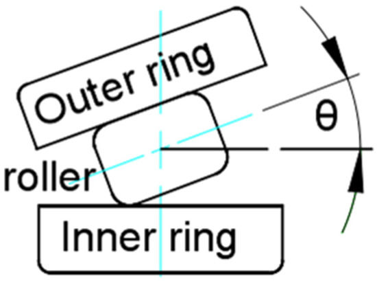
Figure 1.
Schematic diagram of the bearing misalignment (angle θ, existing between the rollers and inner ring, is often referred to as the tilting angle of the roller) [21].
However, case studies on failures caused by bearing deformation induced by improper installation are comparatively smaller, compared to case studies on failures caused by assembly misalignment and other reasons, such as unqualified bearing production [23] and lubrication [24,25].
Therefore, this paper investigated the failure of a cylindrical roller bearing caused by excessive tightening axial force and identified failure modes of the bearing. The influence of tightening axial force on the cylindricity (deformation) was obtained. Additionally, recommendations were provided. It is hoped that the present research can provide a reference for the analysis and prevention of bearing failure induced by improper installation (excessive tightening axial force).
The cylindrical roller bearing was found failure with spalling and wear of the inner and oture ring, broken of the cage after operation for 100h. Additionally, the inner ring is fixed on the shaft by an axial tightening axial force applied by the lock nut. An installation diagram of the cylindrical roller bearing is shown in Figure 2. The installation morphology of the inner ring in the test rig and lock nut, which is related to the failure cause, are shown in Figure 3.
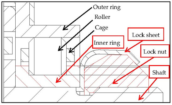
Figure 2.
Installation schematic diagram of the cylindrical roller bearing.
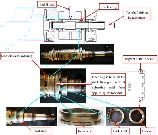
Figure 3.
Installation morphology of the inner ring and assembly schematic diagram of the bearing on the test rig.
According to the installation structure of the inner ring, as shown in Figure 2 and Figure 3, the inner ring raceway will deform and form high cylindricity on one side (causing the sloped shape of the inner ring raceway, due to the different diameter increase of the raceway surface at two ends, such as locations A and B in Figure 4) under excessive tightening axial force; in this situation, it is very easy to cause the single side clearance between the rollers and ring raceway, because it is too small during the service of the bearing, resulting in local contact between one side of the ring raceway and one end of the rollers, as shown in Figure 4. This may cause uneven load distribution with high local contact stress, resulting in contact fatigue spalling and wear, eventually leading to failure of the bearing.
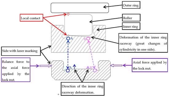
Figure 4.
Schematic of unilateral local contact between inner ring raceway and roller.
2. Materials and Methods
Five cylindrical roller bearings were evaluated in this paper. One bearing was the faulty bearing used for failure analysis. Three bearing were used to study influence of the tightening axial force on the inner bearing. Additionally, one bearing was used for the comparative experiment.
The dimension and working conditions of the bearing are shown in Table 1.

Table 1.
Dimension and working conditions of the bearing.
The inner and outer rings and rollers of the bearings were made of M50 steel, and their microstructures consisted of tempered martensite, primary carbides (Fe,Cr)3C, tempered carbides, and retained austenite. The amount of retained austenite was about 3%. The chemical composition of the M50 steel is shown in Table 2.
Table 2.
Chemical compositions of M50 steel (wt.%).
Additionally, the cage is made of 40CrNiMoA steel, with the microstructure of tempered sorbite. Chemical composition of 40CrNiMoA steel is shown in Table 3.
Table 3.
Chemical compositions of 40CrNiMoA steel (wt.%).
The macroscopic damage morphologies of the bearing were obtained by visual and optical microscope observation. Microscopic damage morphologies of the bearing were examined by scanning electron microscope. The microstructure of the bearing was checked via an optical metallographic microscope. The microhardness was measured with the microhardness tester. The cylindricity of the inner ring raceway was measured with the cylindricity measuring instrument. The contact fatigue test of the bearing, used for verification of the tightening axial force influence on bearing performance, was carried out via bearing test equipment. The above experimental instruments and equipment are shown in Table 4.
Table 4.
Experimental instruments and equipment used in this paper.
3. Results
3.1. Macroscopic and Microscopic Observation
Almost the whole circumferential area of the working track of outer ring raceway was damaged, with the main characteristics of wear and contact fatigue spalling, as shown in Figure 5. The damage, characterized by spalling pits with intermittent distribution on the side with laser marking of the outer ring raceway, was more serious than that of the other side of the outer ring raceway, as shown in Figure 6. There were regular golden and blue-black rings (about 2 mm wide), mainly distributed in the whole circumferential areas on the bearing side, with laser marking (the side with the bearing number engraved on the edge by laser) on the outer diameter surface of the outer ring, while there were blue-black patches on the other side of the outer diameter surface of the outer ring, as shown in Figure 7. These discolouration areas resulted from overheating of the bearing, induced by abnormal wear under high local stress.
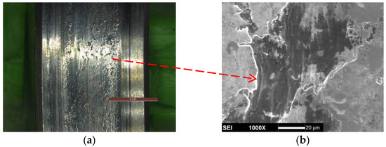
Figure 5.
Wear of the outer ring raceway: (a) macroscopic damage; (b) microscopic damage.
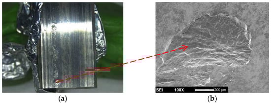
Figure 6.
Intermittent distributed spalling pits of the outer ring raceway: (a) macroscopic damage; (b) microscopic damage.
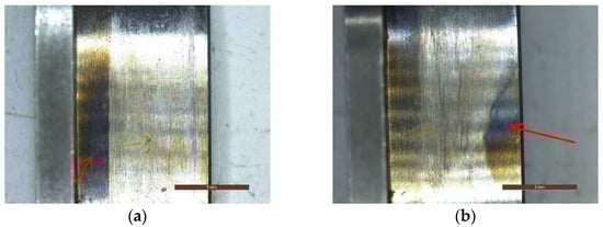
Figure 7.
Discolouration on the outer diameter surface of the outer ring, as the arrow indicated: (a) discolouration corresponded to the bearing side with laser marking; (b) discolouration corresponded to the bearing side with laser marking.
The damage, characterized by spalling pits of the inner ring raceway, was mainly distributed in the areas that corresponded to the bearing side with laser marking, with an axial width about 1 mm, and the circumferential length accounted for 3/4 of the circumference of the outer ring raceway, as shown in Figure 8. The spalling pits showed contact fatigue features with laminar and fan-shaped morphologies, as shown in Figure 9.
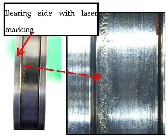
Figure 8.
Macroscopic morphologies of the spalling position of the inner ring raceway.
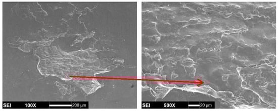
Figure 9.
Microscopic morphologies of the spalling position of the inner ring raceway.
The 20 rollers show a gray-black colour, serious contact fatigue spalling, and wear on the roller surface, which corresponded to the bearing side with laser marking, as shown in Figure 10. Friction and wear of the end face that corresponded to the bearing side with laser marking of the roller are heavier than those of the other end face of the roller, and the discolouration of the end face that corresponded to the bearing side with laser marking of the rollers was also more obvious than that of the other end face of the rollers, as shown in Figure 11 and Figure 12.
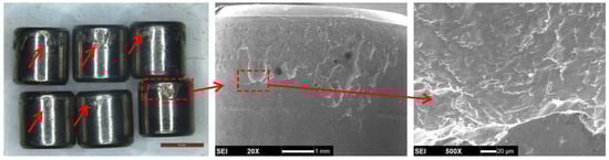
Figure 10.
Surface damages of the rollers.
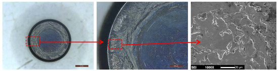
Figure 11.
Damages of the roller end face that corresponded to the bearing side with laser marking.
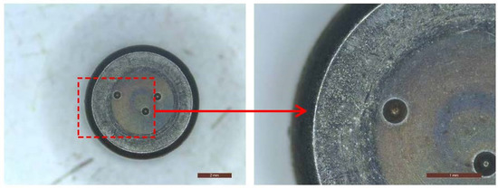
Figure 12.
Damages of the roller end face, away from the bearing side with laser marking.
The beams of six consecutive pockets (the pockets are numbered from No.1 to No.6), in the twenty pockets of the cage, were broken at the corners formed by the beam and side beam; the side beams corresponded to the bearing side with laser marking of the six consecutive pockets, separately broken at the corners near the No.20 of No.1 pockets, as well as at the corners near the No.5 of No.6 pockets; the other side beam of the six consecutive pockets were only broken at the corners near the No.20 of No.1 pockets, as shown in Figure 13. Most of the fractures were invisible, due to serious wear. The three fractures (numbered from No.1 to No.3) of the side beam were visible, with a colour of gray-black, and had their origins in the corner surfaces and flat propagation areas, with fracture ridge and fatigue striations, as shown in Figure 14. Additionally, the side beam surfaces showed severe contact wear morphologies, especially in the surfaces corresponded to the bearing side with laser marking, as shown in Figure 15.
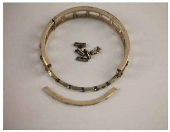
Figure 13.
Macroscopic damage morphology of the cage.
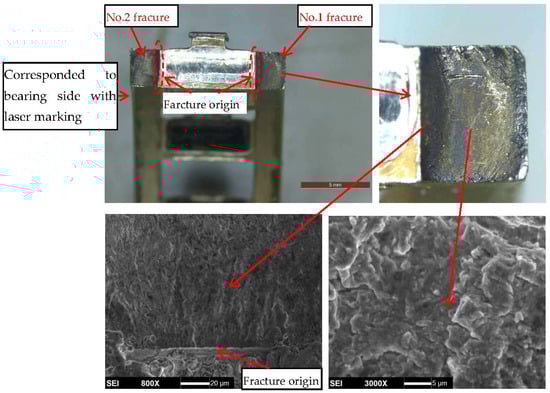
Figure 14.
Typical morphologies of the side beam fractures.
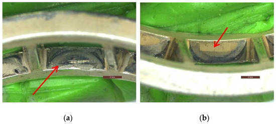
Figure 15.
Contact wear morphologies of the side beams, as the arrow indicated: (a) wear of the side beam, corresponded to the bearing side with laser marking; (b) wear of the other side beam.
3.2. Metallography
There are serious microstructure burns induced by heavy wear between outer ring raceway and rollers in the outer ring raceway, which exhibit as a white quenching burn and gray-black, high-temperature tempering burn. The burned area, corresponding to the bearing side with laser marking, was heavier than that of the other side. Additionally, the deepest part of the burns was almost equivalent to the thickness of the outer ring. The microstructure of the outer ring was a homogeneous structure and consisted of acicular martensite + carbide. The typical microstructure and burns of the outer ring are shown in Figure 16.
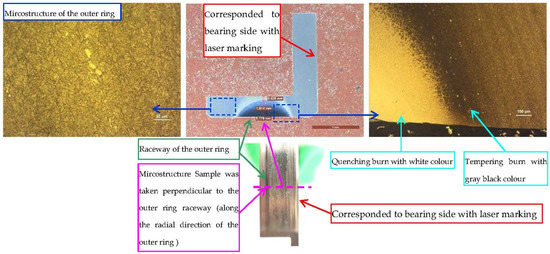
Figure 16.
Typical microstructure and burns of the outer ring.
There are serious microstructure burns induced by heavy wear between rollers and ring raceways in the rollers. The burned area corresponding to the bearing side with laser marking was heavier than that of the other side. The microstructure of the rollers was a homogeneous structure and consisted of acicular martensite + carbide. The typical microstructure and burns of the rollers are shown in Figure 17.
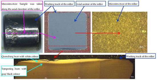
Figure 17.
Typical microstructure and burns of the roller.
The microstructure of the inner ring was a homogeneous structure and consisted of acicular martensite + carbide. The microstructure of the cage was a homogeneous structure and consisted of tempered sorbite.
3.3. Hardness Test
Hardness examinations were respectively carried out on the matrix of the inner ring, outer ring, rollers, and cage. Their hardness met the requirements, as shown in Table 5.
Table 5.
Hardness test results and requirements of the inner ring, outer ring, rollers, and cage.
4. Discussion
(1) Failure modes and direct failure cause
According to the bearing damage characteristics discussed in Section 3.1, the failure modes of the outer ring raceway and rollers were contact fatigue spalling and wear. The failure mode of the inner ring raceway was contact fatigue spalling, and the failure mode of the cage was fatigue fracture. Additionally, fatigue fracture of the cage should occur after spalling and wear of the raceways and rollers because, if the cage fracture occurred first, then the spalling and wear of the raceways and rollers, as well as the axial damage of the raceways and rollers, should be relatively uniform.
The original microstructure of the inner ring, outer ring, roller, and cage were homogeneous structures. The hardness of the inner ring, outer ring, roller, and cage met the required specifications. Therefore, the material quality of the bearing was not responsible for the bearing failure.
The outer ring, inner ring, rollers, and cages all had suffered relatively heavy damage in the sides, corresponding to the bearing side with laser marking, which indicated that the local contact stress in the bearing side with laser marking was too high. That is to say, the high local contact stress, corresponding to the bearing side with laser marking, should be the direct cause of the bearing failure.
(2) Tightening axial force influence analysis and test verification
The diameter of the lock nut was equivalent to the diameter of the inner ring flange. Therefore, a high tightening axial force may lead to the deformation of the inner ring and result in high local stress in some positions.
The influence of the tightening axial force on the inner bearing was analyzed by studying the relationship between the tightening torque of the lock nut and cylindricity variation of the inner ring raceway. The technical required axial tightening torque of the inner ring is 338~372 N·m. Additionally, the minimum axial tightening torque (338 N·m), tightening torque approximately in the middle axial tightening torque of the technical requirements range (350 N·m), and maximum axial tightening torque (372 N·m) were selected to study the relationship. The cylindricity of the inner ring raceway was measured via a cylindricity measuring instrument, both before and after being fixed on the shaft, with different tightening torques. The cylindricity of the inner ring fixed on the shaft was to be measured as shown in Figure 18.

Figure 18.
Cylindricity of the inner ring fixed on the shaft is to be measured.
The tightening torque of the lock nut, as well as the comparable cylindricity of the inner ring raceway, are shown in Table 6. After the tightening torque was applied, the cylindricity of the inner ring raceway was generally greater than it was before the tightening torque is applied. The cylindricity increased, which indicates that the distortion and deformation of the inner ring raceway had been formed by the tightening torque. Additionally, the cylindricity of the inner ring increased with the increase of the tightening torque of the lock nut.
Table 6.
The cylindricity of the bearing inner raceway under different tightening torque (μm).
When large interference was used to install the inner ring, the inner ring deformation and cylindricity increase was induced by the large tightening axial force (375 N·m) that was used, which was 3 N·m larger than the maximum tightening torque of the bearing requirement, and the test of the simulating bearing operation was carried out by bearing contact fatigue test equipment. Before the bearing was installed on the test equipment, cylindricity of the inner ring raceway is 2.90 um, and the cylindricity profile is shown in Figure 19a. After the bearing was installed on the test equipment, the cylindricity of the inner ring raceway increased to 10.98 um, and the cylindricity profile is shown in Figure 19b. The tightening axial force caused obvious the taper deformation of the inner ring raceway. Additionally, the diameters corresponding to the bearing side with laser marking of the inner ring raceway increased obviously at some positions.
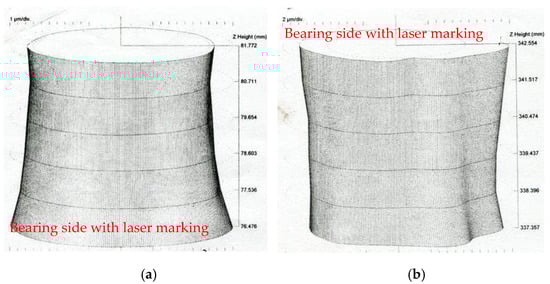
Figure 19.
Cylindricity of the inner ring raceway: (a) before installation; (b) after installation.
The bearing was disassembled and inspected after a 50-h test. There were obvious circumferential contact marks on the outer race raceway, a spalling area with a circumferential length of about 12 mm, and an axial width of about 1.5 mm in the axial end, which corresponded to the bearing side with laser marking of the outer ring raceway, as shown in Figure 20a. There were obvious circumferential contact marks on the inner race raceway and spalling strips, whose circumferential length separately accounted for 2/3 and 1/4 of the circumference of the outer race raceway, which, in the end, corresponded to the bearing side with laser marking; the damage at the other end was not obvious, as shown in Figure 20b. There were obvious circumferential contact marks on the 20 rollers. Additionally, there were spalling strips on the end surfaces corresponding to the bearing side with laser marking of the 13 rollers, as typically shown in Figure 20c. Damages of the cage were mainly characterized by an uneven wear of the pocket and side beams, as shown in Figure 20d.
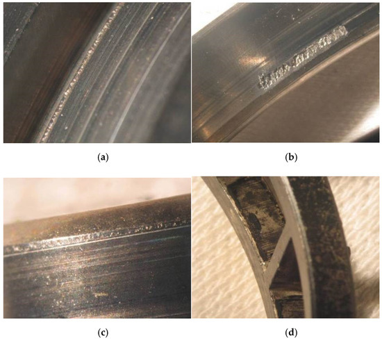
Figure 20.
Damage morphology of the test verification bearing: (a) spalling morphology of the outer ring raceway; (b) spalling morphology of the outer ring raceway; (c) typical spalling morphology of the rollers; (d) wear morphology of the cage.
The severely damaged areas of the working tracks of the outer ring raceway, inner ring raceway, and rollers were located at the working tracks end corresponding to the bearing side with laser marking. This shows that there was excessive local contact stress at the ends of the outer ring raceway, inner ring raceway, and rollers. Additionally, it can be seen that the severely damaged areas of the outer ring raceway, inner ring raceway, and rollers corresponded exactly to the areas with the maximum deformation of the inner ring raceway, by comparing the cylindricity profile of the inner ring raceway and those severely damaged areas. Therefore, the spalling failure of the bearing should be caused by the high tightening axial force.
(3) Comprehensive analysis
The analysis results of the bearing damage morphologies, microstructure, and hardness showed that high local contact stress, corresponding to the bearing side with laser marking, may be the cause of bearing failure. Excessive tightening axial force will cause great deformation and cylindricity increase of the inner ring raceway, which will cause high local contact stress between one side of the ring raceway and one end of the rollers, resulting in contact fatigue spalling and wear failure of the bearing, in the case that the bearing is installed with a large interference. Failure modes of the faulty bearing and test bearing, to verify the excessive tightening axial force, are mainly fatigue spalling. Additionally, the severely damaged areas of the two bearings are located at the working tracks end corresponding to the bearing side with laser marking. Therefore, excessive tightening axial force is the failure cause of the faulty bearing.
After further investigation on the cause of excessive tightening axial force, it was found that tightening torque of lock nut of the faulty bearing was about 100 N·m bigger than the minimum axial tightening torque of the technical requirement. Therefore, excessive tightening axial force is induced by the bigger tightening torque of lock nut.
5. Conclusions
(1) The failure modes of the outer ring raceway and rollers are contact fatigue spalling and wear. The failure mode of the inner ring raceway is contact fatigue spalling. Additionally, failure mode of the cage is fatigue fracture.
(2) The outer ring, inner ring, rollers, and cages all exhibited relatively heavy damage in the sides corresponding to the bearing side with laser marking, when the bearing failure was induced by excessive tightening axial force of the inner ring raceway.
(3) Excessive tightening axial force, induced by the tightening torque of the lock nut, is the cause of the bearing failure. Additionally, the failure mechanism is that excessive tightening axial force causes great deformation and cylindricity increases of the inner ring raceway, which induced high local contact stress between one side of the ring raceways and one end of the rollers, resulting in contact fatigue spalling and wear failure of the bearing.
6. Recommendation
Controlling the tightening axial force, within the range of the technical requirements, is the basic requirement to prevent such bearing failure. However, the following measures can be taken to reduce the influence of the bearing inner ring deformation induced by tightening axial force.
(1) Convexity increase of the inner ring raceway can offset a certain deformation of the inner ring raceway.
(2) Convexity increase of the rollers can improve the bearing ability to resist the deformation of the inner ring raceway [26].
(3) Size decrease of the grinding undercut of the inner ring can improve the ability of the inner ring raceway to resist deformation [27].
Author Contributions
Conceptualization, X.H. and Z.Z.; methodology, X.H.; validation, X.H. and Y.L.; formal analysis, X.H.; investigation, X.H. and Q.D.; resources, X.H. and Y.L.; data curation, Z.Z., C.L. and C.T.; writing—original draft preparation, X.H.; writing—review and editing, Z.Z. supervision, Z.Z., C.L. and C.T.; project administration, C.L.; funding acquisition, C.L. All authors have read and agreed to the published version of the manuscript.
Funding
This research was funded by Independent Innovation Foundation of Aeroengine Corporation of China, grant number ZZCX-2018-026.
Institutional Review Board Statement
Not applicable.
Informed Consent Statement
Not applicable.
Data Availability Statement
Not applicable.
Conflicts of Interest
The authors declare no conflict of interest.
References
- Bhadeshia, H. Steels for Bearings. Prog. Mater. Sci. 2012, 57, 268–435. [Google Scholar] [CrossRef]
- Hwang, Y.-K.; Lee, C.-M. A Review on the tightening axial force Technology of the Rolling Bearing for the Spindle of Machine Tools. Int. J. Precis. Eng. Manuf. 2010, 11, 491–498. [Google Scholar] [CrossRef]
- Madar, E.; Galiki, O.; Klein, R.; Bortman, J.; Nickell, J.; Kirsch, M. A New Model for Bearing Spall Size Estimation Based on Oil Debris. Eng. Fail. Anal. 2021, 134, 106011. [Google Scholar] [CrossRef]
- Kishore, K.; Mukhopadhyay, G. Root Cause Failure Analysis of Pinch Roll Bearing at Hot Strip Mill. J. Fail. Anal. Prev. 2019, 19, 219–229. [Google Scholar] [CrossRef]
- Ban, J.; Liu, X.-L.; Luo, Y.; Zhao, Q. Cause Analysis and Prevention of Flaking of W9Cr4V2Mo Steel Rolling Bearing. Fail. Anal. Prev. 2015, 10, 238–242. [Google Scholar]
- Tauqir, A.; Salam, I.; Haq, A.U.; Khan, A. Causes of Fatigue Failure in the Main Bearing of an Aero-Engine. Eng. Fail. Anal. 2000, 7, 127–144. [Google Scholar] [CrossRef]
- Salam, I.; Tauqir, A.; Haq, A.U.; Khan, A. An Air Crash Due to Fatigue Failure of a Ball Bearing. Eng. Fail. Anal. 1998, 5, 261–269. [Google Scholar] [CrossRef]
- Xu, X.-L.; Yu, Z.-W. Failure Analysis of Tapered Roller Bearing Inner Rings Used in Heavy Truck. Eng. Fail. Anal. 2020, 111, 104474. [Google Scholar] [CrossRef]
- Iliev, H. Failure Analysis of Hydro-Generator Thrust Bearing. Wear 1999, 225–229, 913–917. [Google Scholar] [CrossRef]
- Savaskan, T.; Veinot, D. On the Wear and Failure of High Speed Roller Bearings. Wear 1987, 116, 361–380. [Google Scholar] [CrossRef]
- John, S.K.; Mishra, R.K.; Hari, K.; Ramesha, H.P.; Ram, K.K. Investigation of Bearing Failure in a Turbo Shaft Engine. J. Fail. Anal. Prev. 2020, 20, 34–39. [Google Scholar] [CrossRef]
- Ejaz, N.; Salam, I.; Tauqir, A. Failure Analysis of an Aero Engine Ball Bearing. J. Fail. Anal. Prev. 2006, 6, 25–31. [Google Scholar] [CrossRef]
- Mishra, R.K.; Muduli, S.K.; Srinivasan, K.; Ahmed, S.I. Failure Analysis of an Inter-Shaft Bearing of an Aero Gas Turbine Engine. J. Fail. Anal. Prev. 2015, 15, 205–210. [Google Scholar] [CrossRef]
- Harris, T.A.; Barnsby, R.M.; Kotzalas, M.N. A Method to Calculate Frictional Effects in Oil-Lubricated Ball Bearings. Tribol. Trans. 2001, 44, 704–708. [Google Scholar] [CrossRef]
- Averbach, B.L.; Bamberger, E.N. Analysis of Bearing Incidents in Aircraft Gas Turbine Mainshaft Bearings. Tribol. Trans. 1991, 34, 241–247. [Google Scholar] [CrossRef]
- Bhat, R.R.; Nandi, V.; Manohara, V.; Suresh, S.V. Case Study on Failure of Ball Bearing of an Aeroengine. J. Fail. Anal. Prev. 2011, 11, 631–635. [Google Scholar] [CrossRef]
- Murugesan, V.; Sreejith, P.S.; Sundaresan, P.B.; Ramasubramanian, V. Analysis of an Angular Contact Ball Bearing Failure and Strategies for Failure Prevention. J. Fail. Anal. Prev. 2018, 18, 471–485. [Google Scholar] [CrossRef]
- Prashad, H. Diagnosis of Rolling-Element Bearings Failure by Localized Electrical Current Between Track Surfaces of Races and Rolling-Elements. J. Tribol. 2002, 124, 468–473. [Google Scholar] [CrossRef]
- Dornfeld, D.; Lee, D.E. Precision Manufacturing; Springer: Berlin, Germany, 2008; pp. 1–48, 121–166. [Google Scholar]
- Wang, Q.; Jiang, W.; Liu, H. Effects of manufacture and assembly errors on contact stress on the cylindrical roller bearing. Mod. Mach. 2016, 4, 32–37. [Google Scholar]
- Li, T.; Kolar, P.; Li, X.-Y.; Wu, J. Research Development of Preload Technology on Angular Contact Ball Bearing of High Speed Spindle: A Review. Int. J. Precis. Eng. Manuf. 2020, 21, 1163–1185. [Google Scholar] [CrossRef]
- Zou, L.; Zhou, Q.; Gao, L. Fracture failure analysis of G20Cr2Ni4A steel bearing roller. Heat Treat. Met. 2013, 38, 101–103. [Google Scholar] [CrossRef]
- Mukhopadhyay, G.; Bhattacharya, S. Failure Analysis of a Cylindrical Roller Bearing from a Rolling Mill. J. Fail. Anal. Prev. 2011, 11, 337–343. [Google Scholar] [CrossRef]
- Yu, Z.-Q.; Yang, Z.-G. Failure Analysis of Fatigue Fracture on the Outer Ring of a Cylindrical Roller Bearing in an Air Blower Motor. J. Fail. Anal. Prev. 2012, 12, 427–437. [Google Scholar] [CrossRef]
- Halme, J.; Andersson, P. Rolling Contact Fatigue and Wear Fundamentals for Rolling Bearing Diagnostics—State of the Art. Proc. Inst. Mech. Eng. Part J J. Eng. Tribol. 2010, 224, 377–393. [Google Scholar] [CrossRef]
- Cui, L.; He, Y.; Cai, C. Study on Profile Design of Cylinder Roller Bearing and Its Effect on Fatigue Life. Mach. Des. Res. 2015, 31, 67–70. [Google Scholar]
- Gong, P.; Zhang, J.; Yu, Q.; Zheng, Y. Influence of Grinding Undercut on Rib Deformation for Inner Rings of Cylindrical Roller Bearings. Bearing 2018, 4–6, 10. [Google Scholar]
Publisher’s Note: MDPI stays neutral with regard to jurisdictional claims in published maps and institutional affiliations. |
© 2022 by the authors. Licensee MDPI, Basel, Switzerland. This article is an open access article distributed under the terms and conditions of the Creative Commons Attribution (CC BY) license (https://creativecommons.org/licenses/by/4.0/).