Article

Optimization and Realization of the Coordination Control Strategy for Extended Range Electric Vehicle

School of Automobiles Studies, Tongji University, Shanghai 201804, China
*
Author to whom correspondence should be addressed.
Machines 2022, 10(5), 297; https://doi.org/10.3390/machines10050297
Submission received: 9 March 2022 / Revised: 17 April 2022 / Accepted: 20 April 2022 / Published: 22 April 2022
(This article belongs to the Special Issue Advances in Automation, Industrial and Power Engineering)

Abstract

:
This paper designed a fuzzy adaptive proportional integral differential (PID) control algorithm to optimize the overshoot of speed and torque, fuel consumption and exhaust emissions of the traditional PID control strategy in the process of working condition switching of an extended range electric vehicle. The simulation was carried out in Matlab/Simulink, and the optimization of the control strategy was verified by a bench test. The results show that the fuzzy adaptive PID control strategy effectively reduced the speed overshoot in the process of working condition switching compared with the traditional PID control strategy. The bench test proved that the fuzzy adaptive PID control strategy could effectively optimize the switching process, especially in the speed and torque reduction switching process, and the speed overshoot rate of the fuzzy PID control was greatly reduced to 0.7%, far less than that of the traditional PID control with 6.6%, while the torque overshoot rate was within 0.8%. Additionally, the fuzzy adaptive PID control could effectively reduce the fuel consumption, especially in the switching process of increasing the speed and torque, where the fuel consumption of the fuzzy adaptive PID control was 2.1% and 0.5% lower than that of the traditional PID control, respectively. Additionally, the fuzzy adaptive PID control could also reduce the particulate emissions, especially in the process of increasing the speed and torque, where the number of particles of the fuzzy PID control was 11% and 19% less than that of the traditional PID control, respectively. However, the NOx emissions based on the fuzzy PID control were slightly higher than those of the traditional PID control due to the smooth operation and improved combustion.

1. Introduction

Carbon emissions from the transportation sector account for about 25% of the total emissions globally, and carbon emissions from road transportation account for about 75% of the total emissions from the transportation sector [1]. In order to control the carbon emissions in transportation, the Zero-emission Vehicle Alliance stated in 2015 that only zero-emission vehicles will be sold by 2050, and the current extended range hybrid electric vehicles represent one of the effective ways to realize the transition to zero-emission vehicles [2,3]. Extended range electric vehicle refers to a vehicle which can achieve pure electric driving under the condition of a sufficient on-board battery. When the battery capacity is too low to continue running, the on-board auxiliary power generation device starts to work to provide electricity to drive the vehicle, thus extending the driving range [4,5,6]. The auxiliary power unit (APU), consisting of an internal combustion engine (ICE) and an integrated starter generator (ISG), is the core component of extended range electric vehicles, which can effectively compensate for the insufficient energy density of the battery and provide additional electric power to satisfy the power demand to solve the problem of “mileage anxiety” and “air conditioning anxiety” from battery electric vehicles (BEVs) [7,8]. Extended range electric vehicles can extend the cruising distance by using the APU, which consists of an engine and a generator, without using the larger and more expensive battery pack. Therefore, extended range electric vehicles have great market prospects.
However, in the actual running process of extended range electric vehicles, the extender needs to frequently start and stop and switch mode. In the switching process, due to the dynamic difference between the engine and the generator, it is easy to cause a large torque fluctuation and speed overshoot. The overshoot of speed and torque results in high fuel consumption and high emissions, as well as obvious impact and wear on the mechanical connection of the extender shafting, and it could break the axis, which leads to the loss of function of the whole system and may lead to serious consequences of vehicle damage and death. Better coordinating the control of the engine and generator, reducing the APU adjustment time and reducing overshoot and steady-state errors are some of the main problems in the control of extended range electric vehicles [9,10].
In practical applications, a PID (proportional integral derivative) controller based on classical control theory is mostly used. The actual measured values of speed, power and torque are fed back and compared with the target value of the input end to adjust the control quantity deviation so that the control target is close to the expected value. However, relying solely on closed-loop feedback control cannot achieve ideal results [11]. On this basis, scholars around the world at home and abroad have conducted research aiming at optimizing the extender control strategy. Zhang et al. [12] carried out various constant speed control designs of the engine for range-extended electric vehicles. Fiengo G et al. [13] established the sliding mode torque estimator and PI controller of the engine; on this basis, a combined controller with fast torque control for the inner ring and slow speed control for the outer ring was established to achieve the working point adjustment of the range extender. Zhang et al. [14] analyzed the PID and feedforward PID control methods of engine speed through simulation for the purpose of optimizing PID parameters through the particle swarm optimization algorithm. Li et al. [15] established the ICRE control system based on Compact RIO hardware and LabVIEW, which has the function of the intake throttle PID closed-loop control; the results showed that the speed fluctuation amplitude could be reduced by 30% at the low-power operating condition and 41.7% at the high-power operating condition with the optimal PI parameters of the dual closed-loop control strategy. Xiong et al. [16] analyzed and studied the influence of control parameters on the control effect and introduced intelligent control algorithms such as feedforward control to improve the original control. Li et al. [17] simulated and compared the generator torque control and current control, and the results showed that the torque control was superior to the current control in engine speed tracking when the vehicle accelerated. However, the above research mainly studied the influence of optimized control strategies on the power performance of extended range vehicles and lacked the study of the influence on the fuel consumption and exhaust emissions of extended range vehicles.
In addition, some studies introduced fuzzy control to optimize the performance of the control strategy. Chen et al. [18] discussed the PID and fuzzy control for engine speed by the means of simulation to explore the APU coordination control processing; the results showed that the actual power responded to the change in the required power quickly. Liu et al. [19] designed and simulated the parameters for a fuzzy PID control strategy according to the results of an analysis and comparison of the control performance and inherent limitations of three traditional PID control strategies. The stability and robustness of the control system were improved. Zhang et al. [20] investigated the PID and fuzzy control methods of engine speed by simulation analysis and proposed a coordination control strategy which could realize the coordination control of the engine and generator. However, the above research did not carry out experimental verification, so it lacks credibility. Additionally, the study of the fuzzy PID control strategy combined with simulation and experimental verification with the analysis of power performance, fuel consumption and exhaust emissions was rarely reported.
This study combined intelligent control and fuzzy control theory on the basis of the traditional PID control strategy to optimize the overshoot of speed and torque, fuel consumption and exhaust emissions in the switching process of the range extender, including the switching process of increasing the speed and torque when the power demand increases, and the switching process of decreasing the speed and torque when the power demand decreases. The range extender model was built in Matlab/Simulink, and the mode switching strategy based on fuzzy PID control was simulated. Finally, the power performance, fuel consumption and exhaust emissions of the traditional PID control strategy and fuzzy adaptive PID control strategy were investigated and compared by a bench test, and the effectiveness of the fuzzy adaptive PID control strategy was verified.

2. Methodology

2.1. Fuzzy Adaptive PID Controller

In the speed control process of the extender, due to the complex control system and variable control parameters, which make the parameter setting precision low and performance of the traditional PID controller poor, the control parameters cannot be changed after being set with poor adaptability, resulting in a poor speed control effect and obvious speed overshoot. Fuzzy PID control can adjust the control strategy and parameters according to the change in the control system, in order to achieve the optimal control effect. The following content introduces the fuzzy adaptive PID controller.
According to the principle of proportional integral differential control, a PID controller can be established, and PID parameters can be adjusted in real time during fuzzy control. The actual speed and set speed are taken as input, and the driving force is output through the proportional, integral and differential links of the PID controller [21,22,23,24,25,26,27]. Fuzzy adaptive PID control mainly determines the fuzzy relationship between the PID control parameters K P , K I , K D , the deviation e and the change rate of the deviation e c [28,29,30]. In order to facilitate the implementation of the actual control strategy, fuzzy adaptive control is carried out on two parameters, K P and K I , which have more influence on the change rate and overshoot. In the actual control process, it is necessary to monitor the values of e and e c   in real time and then adjust the PID control parameters according to the fuzzy control principle to adapt to the best control requirements of different deviations and the rate of deviation change, in order to enhance the adaptability of the control system and have better static control and dynamic control performance. In this design, the speed deviation e and speed deviation change rate e c of the range extender are all in the theory domain of [−120, +120], and the theory domain of the output variables Δ K P   and Δ K I   is [−0.24, +0.24].
The fuzzy theory domain of the deviation is as follows: {−6, −5, −4, −3, −2, −1, 0, +1, +2, +3, +4, +5, +6}. The fuzzy theory domain of the deviation change rate is as follows: {−6, −5, −4, −3, −2, −1, 0, +1, +2, +3, +4, +5, +6}. The fuzzy theory domain of the output variables is as follows: {−6, −5, −4, −3, −2, −1, 0, +1, +2, +3, +4, +5, +6}. The quantization factors of the deviation, deviation change rate and output variables are as follows:
K e = 6/120 = 0.05, K c = 6/120 = 0.05, K P = K I = 0.24/6 = 0.04. The input and output variables are divided into seven fuzzy subsets: NB, NM, NS, ZO, PS, PM and PB, which represent, respectively “negative big”, “negative medium”, “negative small”, “zero”, “positive small”, “positive medium” and “positive big”. The corresponding fuzzy control rules table was established according to the actual situation [31,32,33,34,35,36], as shown in Table 1.
Finally, the simulation model of the range extender was established in Matlab. The fuzzy PID controller is encapsulated in a “sub-system” and is named Fuzzy_PID_Controller. It is incorporated into the range extender model. The fuzzy PID controller and the traditional PID controller are used to control the range extender system. The stability of the fuzzy PID controller and the traditional PID controller is compared in the process of working condition switching. The schematic diagram of the simulation model is shown in Figure 1.

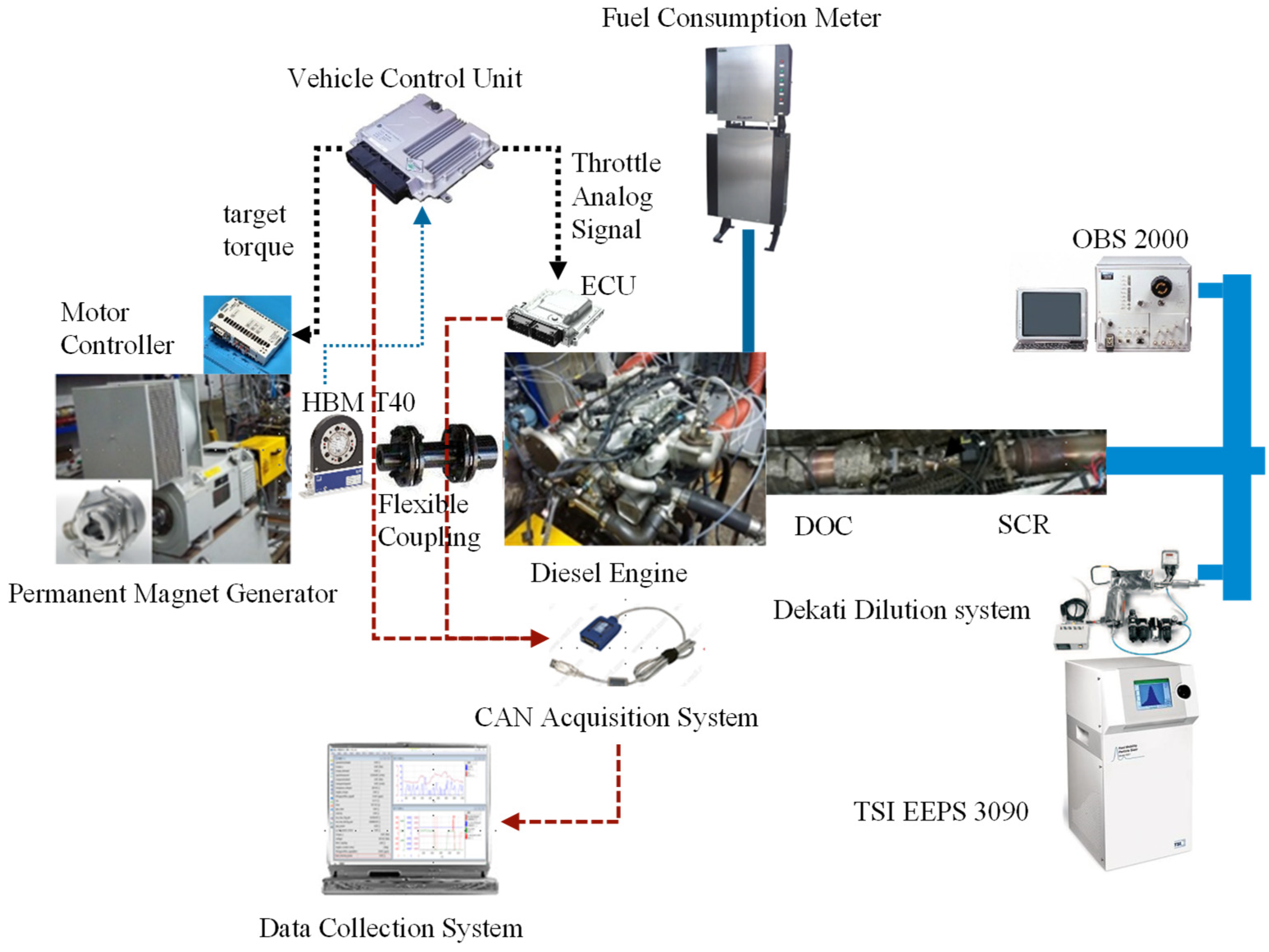
2.2. Bench Test System

A hardware-in-the-loop simulation platform was used in the test. The vehicle controller realized communication, controlled the torque, speed and throttle opening and realized data acquisition at the same time through the CAN (Controller Area Network) bus. The bench test system is shown in Figure 2. The test equipment mainly included a high-pressure common rail diesel engine, engine emission testing equipment, an HBM T40 torque sensor, an engine ECU, an INCA measurement tool and a MotoTune controller calibration and debugging tool. Table 2 shows the technical parameters of a certain type of high-pressure common rail diesel engine, and Table 3 shows the composition and model of the engine emission and fuel consumption testing equipment.
The controller measured the speed of the range extender system in real time which was subtracted from the target speed to obtain the speed deviation, the fuzzy adaptive PID controller was introduced to calculate the throttle opening output and then the PWM module was used to convert the throttle opening output into the corresponding voltage value. Finally, this value was then input to the engine ECU to complete the closed-loop control. Four typical switching conditions were selected in the test, and the selected operating points are shown in Table 4. The speed/torque characteristics, overshoot, NOx and particulate emission characteristics and fuel consumption characteristics of the diesel engine under traditional PID control and fuzzy adaptive PID control were compared in this study.

3. Results and Discussion

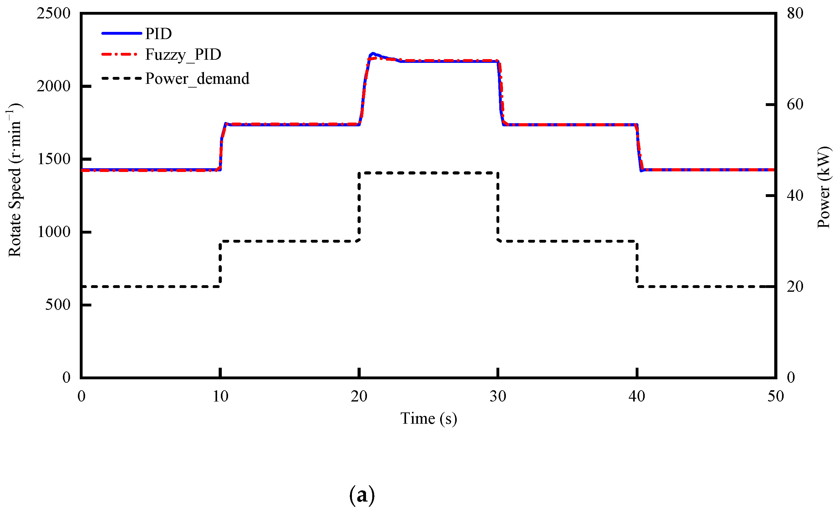
3.1. Simulation Results of Working Condition Switching

The simulation test of mode switching was conducted in Matlab/Simulink. The multi-step input module “Repeating Sequence Interpole” was used to simulate the power demand of the vehicle, which increased from 20 kW to 30 kW and 45 kW every 10 s and then decreased to 30 kW and 20 kW. Thus, we simulated the power of the range extender at multiple working points, including the switching process of increasing the speed and torque when the power demand increased, and the switching process of decreasing speed and torque when the power demand decreased. The simulation results are shown in Figure 3, where “PID” represents the traditional PID control and “Fuzzy_PID” represents the fuzzy adaptive PID control.
As shown in Figure 3, when the required power of the range extender increased from 20 kW to 30 kW, the speed increased from the current 1432 r/min to the target speed 1746 r/min; from 30 kW to 45 kW, the speed increased from the current speed 1746 r/min to the target speed 2180 r/min. It can be seen that, in this process, the traditional PID control had obvious overshoot, where the overshoot rate was 0.8% and 2.8%, respectively, while the fuzzy adaptive PID controller could significantly reduce the overshoot rate, where the overshoot rate was 0.2% and 1.2%, respectively. Similarly, in the switching process of speed and torque reduction with a reduced power demand, there was obvious overshoot in the traditional PID control, while the fuzzy adaptive PID controller basically had no speed overshoot, and the working state of the fixed speed was stable. Therefore, based on the fuzzy adaptive PID control strategy in the process of operating mode switching, through the optimization of the PID control parameters, the speed overshoot of the range extender was effectively reduced, reducing the impact on the extender shafting; compared with the traditional PID control strategy, the effect of the control strategy optimization was remarkable, and the safety and reliability of the shafting during the switching process were effectively guaranteed.

3.2. Test Results of the Fuzzy PID Control Optimization

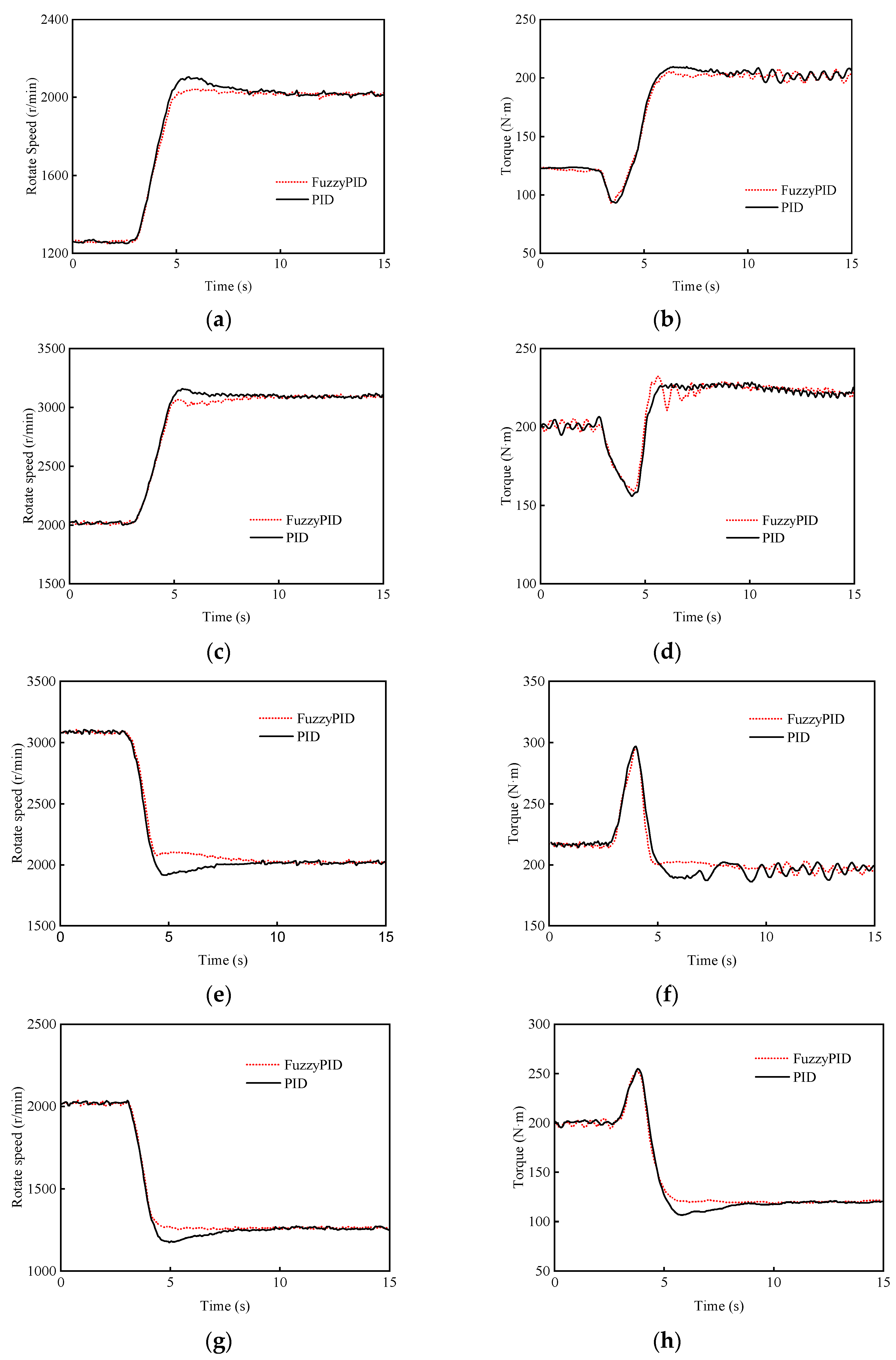
3.2.1. Speed/Torque Characteristics

The speed and torque characteristics in the working condition switching are shown in Figure 4, where “PID” represents the traditional PID control and “FuzzyPID” represents the fuzzy adaptive PID control. According to Figure 4, compared with the traditional PID speed control, the fuzzy adaptive PID speed control significantly reduced the speed and torque overshoot in the process of switching conditions and achieved a more stable transition.
The speed and torque overshoots in the switching process are shown in Table 5. As can be seen in Table 5, the maximum speed overshoot and overshoot rate of the traditional PID control were 85 r/min and 66 r/min, and 4.2% and 2.1%, respectively, in the process of switching 1 and switching 2 under the condition of increasing the speed and torque. When the fuzzy adaptive PID control was used, the maximum speed overshoot and overshoot rate were 24 r/min and −7 r/min, and 1.2% and 0.2%, respectively, and the speed overshoot decreased significantly. In the process of switching 3 and switching 4 of speed and torque reduction, the maximum speed overshoot and overshoot rate of the traditional PID control were −107 r/min and −83 r/min, and 5.3% and 6.6%, respectively, while the maximum speed overshoot and overshoot rate of the fuzzy PID control were 56 r/min and −9 r/min, and 2.8% and 0.7%, respectively. The speed overshoot was significantly reduced.
Similarly, the torque overshoot was alleviated significantly in the switching process after the fuzzy PID speed control was used. In the process of switching 1 and switching 2, the maximum torque overshoot and overshoot rate of the traditional PID control were 7.7 N·m and 8.8 N·m, and 3.8% and 4.1%, respectively, while the maximum torque overshoot and overshoot rate of the fuzzy PID control were 3.4 N·m and 7.9 N·m, and 1.7% and 3.6%, respectively. In the process of switching 3 and switching 4, the maximum torque overshoot and overshoot rate of the traditional PID control were −11 N·m and −13.5 N·m, and 5.5% and 11.1%, respectively, while the torque of the fuzzy PID control had almost no overshoot, and the overshoot rate was less than 0.8%. It can be seen that the torque overshoot was significantly reduced after the fuzzy adaptive PID control was used.

3.2.2. Fuel Consumption Characteristics

The fuel consumption characteristics during the switching test are shown in Figure 5. Figure 5 shows that, compared with the traditional PID control, the fuzzy adaptive PID control achieved stabler mode switching, and the overshoot of the rotational speed and torque was greatly reduced, so when increasing the speed and torque during the process of switching 1 and switching 2, the fuel consumption of the fuzzy adaptive PID control was 2.1% and 0.5% lower than that of the traditional PID control, respectively; however, in the process of switching 3 and switching 4 of the speed and torque reduction, the fuel consumption was basically the same. Overall, compared with the traditional PID control, the fuel consumption of the fuzzy PID control was lower, and the fuzzy PID control achieved a stabler switching process.

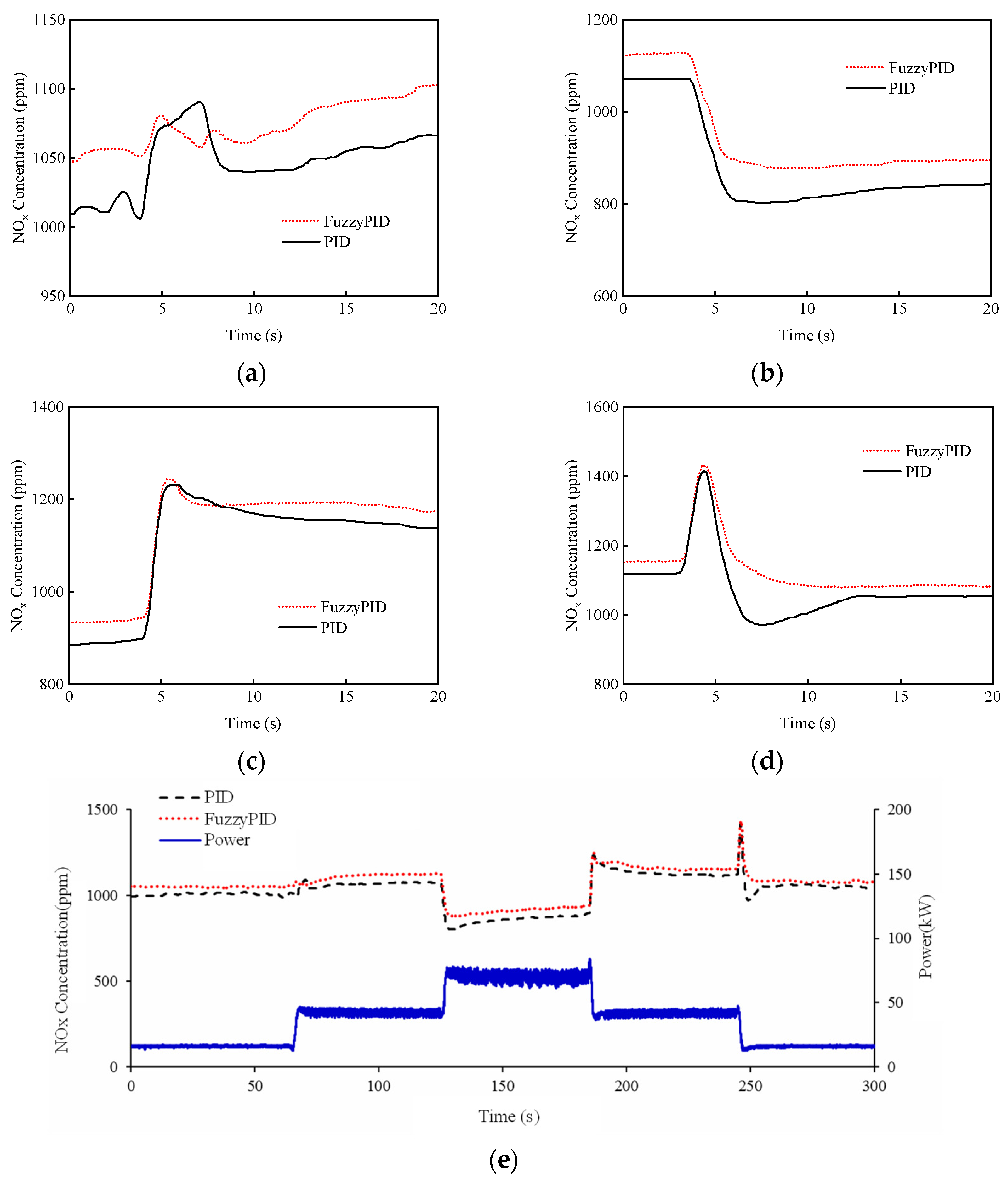
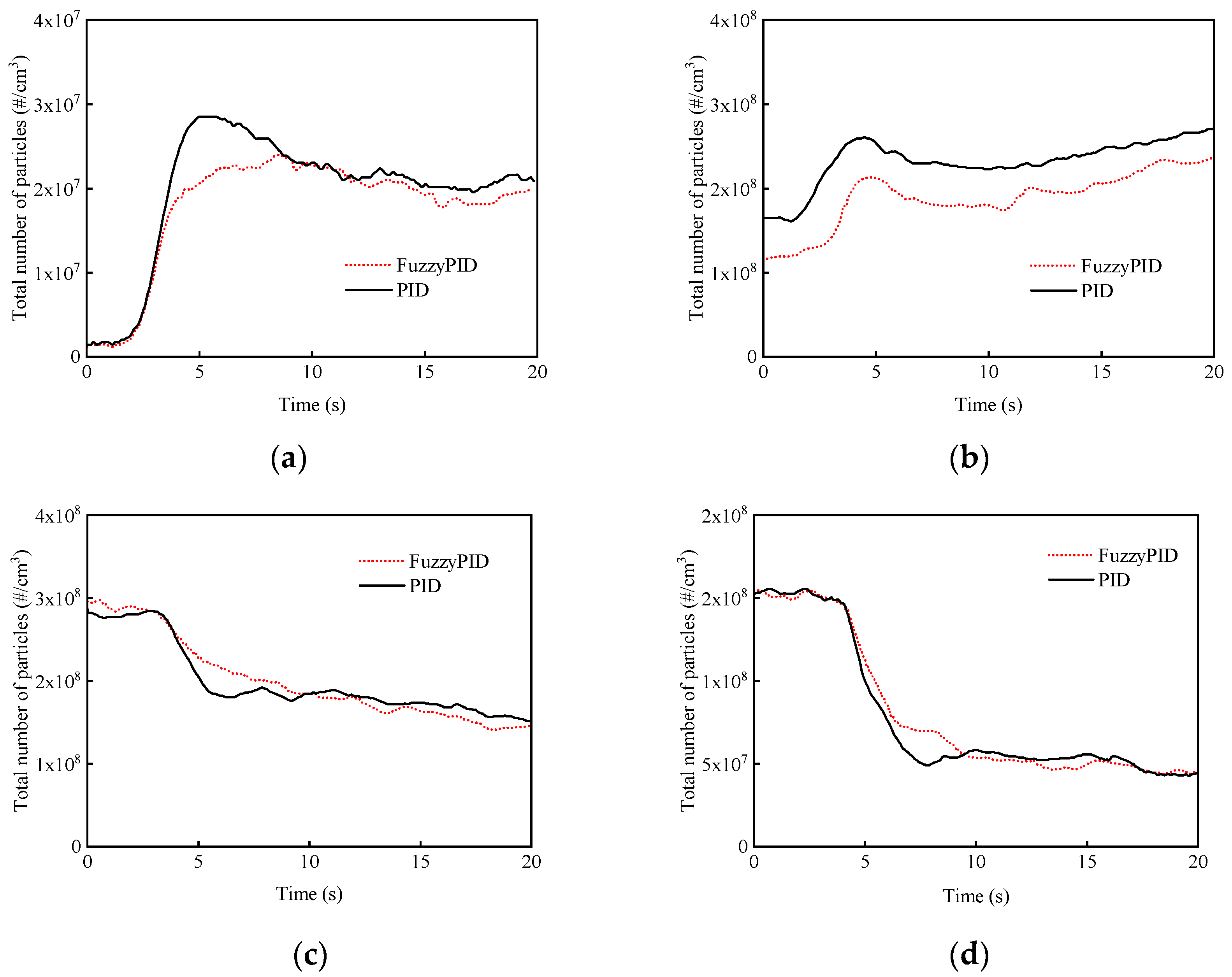
3.2.3. Emission Characteristics

The NOx emission characteristics of the two PID control modes during the switching process are shown in Figure 6. Figure 6 shows that, whether in the steady state or in the transient process of switching, the NOx emissions under the fuzzy PID control were slightly higher than those under the traditional PID control. The reason was that the fuzzy PID control made the engine speed more stable and the combustion in the cylinder was optimized, which led to a rise in the maximum combustion temperature in the cylinder, thus promoting the generation of NOx [37]. In addition, the NOx emissions of the engine at high load and high power were lower than those at low load and low power; this was because the high load and high power were close to the external characteristics of the engine, the decrease in the air–fuel ratio resulted in a relative lack of oxygen content, the combustion deteriorated, the maximum combustion temperature in the cylinder decreased, the engine reached a higher speed and the retention time of gas in the cylinder was shortened, thus leading to a reduction in NOx emissions [38,39].
The particulate emission characteristics in the process of working condition switching of the two PID control modes are shown in Figure 7. It can be seen in Figure 7 that the number of particles was closely related to the change in speed. In the process of switching 1 and switching 2, the number of particles of the fuzzy PID control was 11% and 19% less than that of the traditional PID control, respectively. This was because the speed overshoot was less than that of the traditional PID control, the speed control was more stable, the combustion in the cylinder was better and the generation of particles was inhibited, meaning the number of particles of the fuzzy PID control was less than that of the traditional PID control. In the process of switching 3 and switching 4, the number of particles of the two control methods was basically the same. In general, the particulate emissions of the fuzzy PID control were less than those of the traditional PID control.

4. Conclusions

In this paper, a fuzzy adaptive PID control strategy was designed to optimize the power performance, economy performance and emission performance of the traditional PID control strategy in the process of working condition switching of an extended range electric vehicle. The working condition switching between the two control modes was simulated in Matlab/Simulink, according to the actual control effect, the system output deviation e and deviation change rate e c were taken as the input of the fuzzy PID controller and the PID control parameters Δ K P   (proportional regulation coefficient) and Δ K I   (integral regulation coefficient) were obtained by fuzzy reasoning, in order to achieve the optimal adjustment of the PID parameters. In addition, the experimental verification was carried out based on a hardware-in-the-loop simulation platform. The conclusions are as follows:
(1)
Based on the fuzzy adaptive PID control strategy, the power performance, fuel consumption and exhaust emissions of the extended range electric vehicle were greatly improved.
(2)
The simulation results show that, compared with the traditional PID control, the fuzzy adaptive PID control significantly reduced the speed overshoot in the process of condition switching, and the control performance optimization effect was obvious. Additionally, the experimental results verify the optimization of the fuzzy adaptive PID control. Compared with the traditional PID control, the fuzzy PID control significantly reduced the fluctuation in the speed and torque. Especially in the process of speed and torque reduction, in switching 3 and switching 4, the overshoot rate of the fuzzy PID control speed was 2.8% and 0.7%, respectively, while the overshoot rate of the torque was less than 0.8%, which was significantly smaller than the traditional PID control.
(3)
Comparing the fuel consumption between the two control methods, the fuel consumption of the fuzzy PID control was lower, especially in the process of increasing the speed and torque, where the fuel consumption of the fuzzy adaptive PID control was 2.1% and 0.5% lower than that of the traditional PID control, respectively, and the fuzzy PID control achieved a stabler switching process.
(4)
Comparing the emission characteristics between the two control methods, the NOx emissions based on the fuzzy PID control were higher than those of the traditional PID control; the emission of particles of the fuzzy PID control was less than that of the traditional PID control, especially during the process of increasing the speed and torque, where the number of particles of the fuzzy PID control was 11% and 19% less than that of the traditional PID control, respectively.

Author Contributions

Writing—review and editing, K.Z.; project administration, D.L.; resources, Y.Z.; supervision, L.F. All authors have read and agreed to the published version of the manuscript.

Funding

This research was funded by National Key Research and Development Program of China, grant number 2021YFB2500801.

Institutional Review Board Statement

Not applicable.

Informed Consent Statement

Not applicable.

Acknowledgments

This study was sponsored by the National Key Research and Development Program of China (2021YFB2500801).

Conflicts of Interest

The authors declare no conflict of interest.

References

  1. International Energy Agency (IEA). CO2 Emissions from Fuel Combustion 2018 Highlights; International Energy Agency: Paris, France, 2018. [Google Scholar]
  2. Harrison, G.; Thiel, C. An exploratory policy analysis of electric vehicle sales competition and sensitivity to infrastructure in Europe. Technol. Forecast. Soc. Chang. 2017, 114, 165–178. [Google Scholar] [CrossRef]
  3. Pi, J.M.; Bak, Y.S.; You, Y.K.; Park, D.K.; Kim, H.S. Development of route information based driving control algorithm for a range-extended electric vehicle. Int. J. Automot. Technol. 2016, 17, 1101–1111. [Google Scholar] [CrossRef]
  4. Aharon, I.; Kuperman, A. Topological overview of powertrains for battery-powered vehicles with range extenders. IEEE Trans. Power Electron. 2011, 26, 868–876. [Google Scholar] [CrossRef]
  5. Tate, E.D.; Harpster, M.O.; Savagian, P.J. The electrification of the automobile: From conventional hybrid, to plug-in hybrids, to extended-range electric vehicles. SAE Int. J. Passeng. Cars-Electron. Electr. Syst. 2009, 1, 156–166. [Google Scholar] [CrossRef] [Green Version]
  6. Ren, G.Z.; Shan, S.; Ma, G.Q.; Shang, X.B.; Zhu, S.L.; Zhang, Q.Y.; Yang, T.Q. Review of energy storage technologies for extended range electric vehicle. J. Appl. Sci. Eng. 2014, 22, 69–82. [Google Scholar]
  7. Ahmada, S.; Bathaee, S.M.T.; Hosseinpour, A.H. Improving fuel economy and performance of a fuel-cell hybrid electric vehicle (fuel-cell, battery, and ultra-capacitor) using optimized energy management strategy. Energy Convers. Manag. 2018, 160, 74–84. [Google Scholar] [CrossRef]
  8. Qu, X.D.; Wang, Q.N.; Yu, Y.B. A Study on the control strategy for APU in a extended-range EV. Automot. Eng. 2013, 35, 763–768. [Google Scholar]
  9. Hou, J.; Yao, D.W.; Wu, F.; Lü, C.L.; Wang, H.; Shen, J.H. Control strategy for electric vehicle range-extender based on hybrid excitation generator. J. Shanghai Jiao Tong Univ. 2021, 55, 206–212. [Google Scholar]
  10. Zha, Y.F.; Song, J.L.; Zhang, Q.Y.; Liu, G.Q.; Guo, R.H. Optimisation of control strategy of a range-extended electric bus. Int. J. Electr. Hybrid Vehicles 2019, 11, 1–11. [Google Scholar] [CrossRef]
  11. Yin, C.L.; Zhang, Y.X.; Zhang, J.W. PID control of engine speed tuning for hybrid electric vehicle. J. Shanghai Jiao Tong Univ. 2004, 11, 1913–1916. [Google Scholar]
  12. Zhang, J.Y.; Jiao, X.H. Adaptive coordinated control of engine speed and battery charging voltage. J. Control Theory Appl. 2008, 6, 69–73. [Google Scholar] [CrossRef]
  13. Fiengo, G.; Glielmo, L.; Vasca, F. Control of auxiliary power unit for hybrid electric vehicles. IEEE Trans. Control Syst. Technol. 2017, 15, 1122–1130. [Google Scholar] [CrossRef]
  14. Zhang, H.; Fu, L.; Song, J.J.; Yang, Q.Q. Power energy management and control strategy study for extended-range auxiliary power uni. Energy Procedia 2016, 104, 32–37. [Google Scholar] [CrossRef]
  15. Li, M.L.; Ding, W.Q.; Zeng, X.Y.; Zhong, Z.M.; Hu, Z.J.; Yuan, D.K.; Li, L.G. Optimization of speed fluctuation of internal combustion engine range extender by a dual closed-loop control strategy. SAE Tech. Pap. 2021, 1, 0782. [Google Scholar]
  16. Xiong, W.Y.; Ye, J.; Gong, Q.; Feng, H.; Xu, J.B.; Shen, A.W. A range-extender engine speed control strategy with generator torque as an auxiliary input. Control Eng. Pract. 2020, 103, 104596. [Google Scholar] [CrossRef]
  17. Li, J.Q.; Wang, Y.H.; Chen, J.W. Research of APU dynamic characteristics modeling and coordination control in electric vehicles. Energy Procedia 2016, 88, 921–927. [Google Scholar] [CrossRef] [Green Version]
  18. Chen, L.S.; Wang, X.L.; Huang, X.E.; Gan, P.; Cheng, W. Modeling and simulation of the auxiliary power system in extended range electric vehicle. Appl. Mech. Mater. 2013, 397–400, 1858–1862. [Google Scholar] [CrossRef]
  19. Liu, H.W.; Lei, Y.L.; Fu, Y.; Li, X.Z. Optimization and realization on the coordination control strategy for auxiliary power unit of range-extended electric vehicle. Proc. Inst. Mech. Eng. Part D J. Automob. Eng. 2021. [Google Scholar] [CrossRef]
  20. Zhang, H.; Yang, Q.Q.; Song, J.J.; Fu, L. Study and realization on power energy distribution control for auxiliary power unit. Energy Procedia 2017, 105, 2601–2606. [Google Scholar] [CrossRef]
  21. Mizumoto, M. Min-max-gravity method versus product-sum-gravity method for fuzzy control. In Proceedings of the IV IFSA Congress (Part E); IEEE: Brussels, Belgium, 1991; pp. 127–130. [Google Scholar]
  22. Xu, J.X.; Hang, C.C.; Liu, C. Parallel structure and tuning of a fuzzy PID controller. Automatica 2000, 36, 673–684. [Google Scholar] [CrossRef]
  23. Kocaarslan, I.; Cam, E. Experimental modeling and simulation with adaptive control of a power plant. Energy Convers. Manag. 2007, 48, 787–796. [Google Scholar] [CrossRef]
  24. Zhang, Z. A flexible new technique for camera calibration. IEEE Trans. Pattern Anal. Mach. Intell. 2000, 22, 1330–1334. [Google Scholar] [CrossRef] [Green Version]
  25. Greg, M.; Mike, M.D.; Mark, B.S. Towards an understanding of adaptive cruise control. Transport. Res. 2001, 9, 3–51. [Google Scholar]
  26. Higashimata, A.; Adachi, K.; Hashizume, T.; Tange, S. Design of a headway distance control system for ACC. JSAE Rev. 2001, 22, 15–22. [Google Scholar] [CrossRef]
  27. Mayr, R. Robust performance for autonomous intelligent cruise control systems. In Proceedings of the Conference on Decision and Control, Tampa, FL, USA, 16 December 1998; pp. 487–492. [Google Scholar]
  28. Mizumoto, M. Realization of PID controls by fuzzy control methods. Fuzzy Sets Syst. 1995, 70, 171–182. [Google Scholar] [CrossRef]
  29. Huang, Y.; Yasunobu, S. A General Practical Design Method for Fuzzy PID Control from Conventional PID Control. In Proceedings of the IEEE International Conference on Fuzzy Systems, Honolulu, HI, USA, 12–17 May 2002; pp. 969–972. [Google Scholar]
  30. Zhao, Z.Y.; Tomizuka, M.; Isaka, S. Fuzzy gain scheduling of PID controllers. IEEE Trans. Syst. Man Cybern. 1993, 23, 1392–1398. [Google Scholar] [CrossRef] [Green Version]
  31. Wu, Z.Q.; Masaharu, M. PID type fuzzy controller and parameters adaptive method. Fuzzy Sets Syst. 1996, 78, 23–35. [Google Scholar]
  32. Jiang, J.Y.; Ke, T. Design and Simulation of fuzzy PID controller based on Simulink. In Proceedings of the 3rd International Conference on Mechanical Engineering and Intelligent Systems (ICMEIS 2015), Yinchuan, China, 15–16 August 2015. [Google Scholar]
  33. Kazemian, H.B. Comparative study of a learning fuzzy PID controller and a self-tuning controller. ISA Trans. 2001, 40, 245–253. [Google Scholar] [CrossRef]
  34. Gyöngy, I.J.; Clarke, D.W. The automatic tuning and adaptation of PID controllers. Control Eng. Pract. 2005, 14, 149–163. [Google Scholar] [CrossRef]
  35. Mohan, B.M.; Sinha, A. The simplest fuzzy PID controllers: Mathematical models and stability analysis. Soft Comput. 2006, 10, 961–975. [Google Scholar] [CrossRef]
  36. Woo, Z.W.; Chung, H.Y.; Lin, J.J. A PID type fuzzy controller with self-tuning scaling factors. Fuzzy Sets Syst. 2000, 115, 321–326. [Google Scholar] [CrossRef]
  37. KO, J.; Jin, D.; Jang, W.; Myung, C.L.; Kwon, S.; Park, S. Comparative investigation of NOx emission characteristics from a Euro 6-compliant diesel passenger car over the NEDC and WLTC at various ambient temperatures. Appl. Energy. 2017, 187, 652–662. [Google Scholar] [CrossRef]
  38. Lou, D.M.; Sun, Y.Z.; Yu, H.Y.; Tan, P.Q.; Hu, Z.Y. Performance evaluation method and experiment for diesel engine under idle transient operation condition based on smoke emission limit. Trans. Chin. Soc. Agric. Eng. 2017, 33, 111–116. [Google Scholar]
  39. Shen, Y.P.; He, Z.D.; Liu, D.Q.; Xu, B.J. Optimization of fuel consumption and emissions of auxiliary power unit based on multi-objective optimization model. Energies 2016, 9, 90. [Google Scholar] [CrossRef] [Green Version]
Figure 1. Schematic diagram of the simulation model: (a) The model of the Fuzzy_PID sub-system; (b) Simplified model for the comparison between the fuzzy PID controller and the PID controller.
Machines 10 00297 g001
Figure 2. Bench test system.
Machines 10 00297 g002
Figure 3. Simulation results of the range extender switching process: (a) Total switching process of the range extender; (b) The switching process of increasing the speed and torque with an increased power demand; (c) The switching process of speed and torque reduction with a power demand reduction.
Machines 10 00297 g003aMachines 10 00297 g003b
Figure 4. Variation in speed and torque during the process of working condition switching: (a) Change in speed during switching 1. (b) Change in torque during switching 1. (c) Change in speed during switching 2. (d) Change in torque during switching 2. (e) Change in speed during switching 3. (f) Change in torque during switching 3. (g) Change in speed during switching 4. (h) Change in torque during switching 4.
Machines 10 00297 g004
Figure 5. Engine fuel consumption characteristics in the process of working condition switching: (a) switching 1; (b) switching 2; (c) switching 3; (d) switching 4.
Machines 10 00297 g005
Figure 6. The NOx emission characteristics in the process of working condition switching: (a) switching 1; (b) switching 2; (c) switching 3; (d) switching 4; (e) overall switching process.
Machines 10 00297 g006
Figure 7. Particulate emission characteristics in the process of working condition switching: (a) switching 1; (b) switching 2; (c) switching 3; (d) switching 4.
Machines 10 00297 g007
Table 1. Fuzzy control table for Δ K P and Δ K I .
Control   Parameters   e e c
NBNMNSZOPSPMPB
Δ K P NBPBPBPBPBPBPBPB
NMPBPMPMPMPMPMPB
NSPSPMPMPSPMPMPS
ZOZOZOZOZOZOZOZO
PSPSPMPMPSPMPMPS
PMPBPMPMPMPMPMPB
PBPBPBPBPBPBPBPB
Δ K I NBNBNBNMNBNMNBNB
NMNBNBNMNMNMNBNB
NSPSPSPSPSPSPSPS
ZOPBPBPBPBPBPBPB
PSPSPSPSPSPSPSPS
PMNBNBNMNBNMNBNB
PBNBNBNMNMNMNBNB
Table 2. Main parameters of the engine.
ProjectParameter
Number of cylinders4
Engine displacement (L)1.85
Cylinder diameter × stroke (mm)80 × 92
Compression ratio18.5
Calibration power/speed (kW)/(r/min)70/3000
Maximum torque/speed (N·m)/(r/min)244/2400
EmissionChina V vehicle emission standard
Table 3. Engine emission and fuel consumption testing equipment and models.
Test EquipmentModelAccuracy
Particle size analyzerTSI EEPS-3090-
Conventional gas analyzerHORIBA OBS-2200±0.3%
Dilution systemDekati DI-2000-
Fuel consumption meterToCeil-CMF<0.1%
Table 4. Main test conditions.
Working ConditionInitial Speed (r·min−1)
and Torque (N·m)
End Speed (r·min−1)
and Torque (N·m)
Switching 1Minimum power point
1263/122
Minimum fuel consumption power point
2000/200
Switching 2Minimum fuel consumption power point
2000/200
Maximum power point
3090/215
Switching 3Maximum power point
3090/215
Minimum fuel consumption power point
2000/200
Switching 4Minimum fuel consumption power point
2000/200
Minimum power point
1263/122
Table 5. Speed and torque overshoot during switching between the traditional PID and fuzzy PID working conditions.
ItemsOperating Mode SwitchingParametersPIDThe Fuzzy PID
speedSwitching 1Overshoot8524
Overshoot rate (%)4.21.2
Switching 2Overshoot66−7
Overshoot rate (%)2.10.2
Switching 3Overshoot−10756
Overshoot rate (%)5.32.8
Switching 4Overshoot−83−9
Overshoot rate (%)6.60.7
torqueSwitching 1Overshoot7.73.4
Overshoot rate (%)3.81.7
Switching 2Overshoot8.87.9
Overshoot rate (%)4.13.6
Switching 3Overshoot−110.9
Overshoot rate (%)5.50.45
Switching 4Overshoot−13.5−0.9
Overshoot rate (%)11.10.74
Publisher’s Note: MDPI stays neutral with regard to jurisdictional claims in published maps and institutional affiliations.

