Article

Analytical Determination and Influence Analysis of Stiffness Matrix of Ball Bearing under Different Load Conditions

1
Key Laboratory of Education Ministry for Modern Design and Rotor-Bearing System, Xi’an Jiaotong University, Xi’an 710049, China
2
Luoyang Bearing Research Institute Co., Ltd., Luoyang 471039, China
*
Author to whom correspondence should be addressed.
Machines 2022, 10(4), 238; https://doi.org/10.3390/machines10040238
Submission received: 16 February 2022 / Revised: 16 March 2022 / Accepted: 22 March 2022 / Published: 28 March 2022

Abstract

:
Bearing stiffness, as one of the most important service characteristics for ball bearing, plays a crucial role in the bearing design and rotor dynamic analysis. To rapidly and accurately calculate the stiffness matrix of ball bearing under the arbitrary load conditions, a 5-DOF analytical model for bearing stiffness matrix analysis has been established by the ball–raceway contact analysis, implicit/explicit differential method, and matrix operations. The model has been validated comparing with the previous methods and experimental results. Based on this, the model has been used to investigate the influences of the load and operation conditions, the structural parameters variation on stiffness of ball bearing. The results show that property increasing axial preload can inhibit the attenuation of speed-varying stiffness, and the contact states between balls and raceways also have significant influence on the change in the stiffness of ball bearings. Besides, a larger curvature coefficient of inner raceway and a small curvature coefficient of outer raceway can effectively improve the stiffness of ball bearing at high speed. Therefore, the proposed method can be a useful tool in bearing optimize design and performance analysis of ball and rotor system under various load conditions.

1. Introduction

As the key supporting parts in high-speed rotor system, rolling bearings are widely used across numerous rotating mechanical systems, including aerospace, automobile, machine tool, etc. With the rapid development of the modern industry, there is demand that the service performance of ball bearing must be improved to meet the higher operation requirement of mechanical system. To guarantee the optimum performance, the design and use parameters of rolling bearing should be adjusted by the designers and users according to the practical operation conditions, and an accurate and efficient mathematical model of bearing can be used to reduce the cost and cycle.
During the past decades, a large number of algorithms and methods have been presented in bearing modeling and analysis. In the earlier studies [1,2,3,4], the inertia forces of balls have been neglected, which may cause a considerable error in bearing analysis and characteristic prediction, especially for the high-speed operation condition. To improve the calculation accuracy of bearing analysis, Jones [5] proposed a classical mathematic model with the “Raceway Control Hypothesis” for ball bearing subjected to the combined radial, axial, and moment loads. In this model, the effect of the inertia forces of the balls are considered. Without the Raceway Control Hypothesis, Harris [6] developed a comprehensive model based on the lubrication analysis of ball–raceway contact area, and this model can be used in the bearing skidding behavior prediction and friction power loss calculation. In addition, the experimental results show that the partial results obtained from the “Raceway Control Hypothesis (RCH)” were not precise enough, thus the “Raceway Control Hypothesis” may be only suitable for ball bearing under some specific conditions. To overcome the above shortcomings, the more accurate mechanics and kinematics of local ball have been presented without the RCH in the following research [7,8,9]. In addition, a serial of dynamic models [10,11,12,13,14,15] of ball bearing have been presented in recently years to obtain and investigate the instantaneous motion and mechanics states of ball bearing under running condition, and the most representative study was proposed by Gupta [11,12]. In his model, the relative action relations among the bearing internal components and lubricant influences were fully taken in account. However, the model is time-consuming.
Bearing stiffness, as an important characteristic of ball bearing, has significant effects on the vibration, the carrying capacity, and the rotation accuracy of bearing and rotor system. An accuracy mathematical model can not only be used to guide the design of ball bearing [16] but can also be used in the dynamic properties prediction of rotor-bearing system [17,18,19]. Therefore, a great deal of models for bearing stiffness calculation have been proposed. In the earlier studies, researchers mainly focused on the radial and axial stiffness of rolling bearing. Gargiulo [20] and Wardle [21] separately gave a set of empirical formulas to predict the radial and axial stiffness of rolling bearing, and these formulas are still used in the estimation of bearing stiffness due to its simple and ease of use. To obtain the complete expressions of bearing stiffness matrix, a mathematic model of ball bearing has been presented by Houpert [22] and Hernot [23], but the dynamic forces of balls were ignored. Liu [24] gave a convenient method, called the Newton–Raphson method, for the analytical calculation of the stiffness of ball bearing stiffness under combined load but did not consider the influence of speed. However, the inertia forces of balls play a key role in the stiffness for ball bearing at the high-speed condition. In addition, the representative studies conducted by Lim and Singh [25,26,27] showed that only considering the axial and radial stiffness is not sufficient to explain the flexural and out-of-plane motions of ball bearing, so a complete stiffness matrix solution, including the tilting stiffness and off-diagonal cross-coupling terms, is necessary to describe the influences of ball bearing on vibration transmission. In order to quickly obtain bearing stiffness matrix, the finite difference method has been used to calculate the numerical differentiation of stiffness matrix firstly [28,29]. On this basis, Yang [30,31] calculated and analyzed the stiffness of the single bearing and complex rotor system. However, the calculation accuracy of the above method depends on the step and is difficult to guarantee. Therefore, the full-analytical and semi-analytical model of bearing stiffness solution have been proposed and have been widely used in practical engineering. Noel [32] gave a comprehensive algorithm for the analytical method of bearing stiffness matrix, and the inertia forces of balls have been fully considered to lead an exact solution. Fang [33] gave the complete analytical expression of the bearing stiffness matrix based on an improved model and classified the stiffness elements in the bearing stiffness matrix. However, there is no comparison and verification. Xia [34] introduced the implicit differential theory for the bearing stiffness calculation, but the detailed derivation process was not given. Gunduz and Singh [35] calculated and studied the stiffness matrix of the double-row ball bearings with different arrangements, but this model has neglected the dynamic effect of ball. Tsuha N [36] calculated the stiffness of the cylindrical roller bearing more accurately through an innovative EHL force model, but the model could not be directly applied to ball bearings.
Besides, based on the FE method, Guo and Parker [37] calculated and analyzed the stiffness of rolling bearing with different structural parameters, respectively, and the results have a good consistency with the analytical model and experiments. Based on the above stiffness model, some research [38,39,40] extended to study the time-varying stiffness of ball bearing caused by orbital motion and defects.
Besides the theoretical research, several experiments for bearing stiffness measuring were also conducted. Karus et al. [41] built a transmission test rig to measure the stiffness and damping of ball bearing under different preload. Walford and Stone [42] measured the radial and axial stiffness for ball bearings in a pair under oscillating condition on a test rig. Matti Rantatalo [43] and J.Jedrzejewski [44] also conducted a series of experiments on high spindle-bearing system, and the obvious stiffness attenuation with the rotating speed has been presented in both experimental results.
Above all, though the solution method of bearing stiffness matrix was widely studied, there still exist several problems that the influences factors on bearing stiffness have not fully considered [18,20,21,22,23,24,32,34] and the stiffness calculation has numerical stability problems [28,29,30,31]. In addition, considering the various operation conditions of ball bearings, most of the previous models of bearing stiffness matrix calculation are only suitable for ball bearing under normal load conditions. Therefore, it is still needed to present a comprehensive analytical model for stiffness calculation of ball bearing under arbitrary load conditions. Besides, in order to guide bearing design, the details of effect of the speeding speed, structure parameters on the stiffness, and stiffness variations of the ball bearing under different conditions need to be studied.
This paper presents a quasi-static model without Raceway Control Hypothesis of ball bearing under arbitrary operation conditions, and a comprehensive analytical model for the 5-DOF stiffness matrix calculation of ball bearing is proposed. Based on the contact analysis of balls and raceways for ball bearing at operation conditions, the proposed algorithm can be applied to calculate and analyze the stiffness matrix for ball bearing under the arbitrary load conditions and rotating speeds. Besides, on this basis of proposed model, the influences of the external loads (including axial preload), rotating speeds, and structural parameters on bearing stiffness are analyzed in detail. The research of this method and the discussion of these influence laws provide a useful tool for the optimal design of bearings and the performance analysis of ball and rotor systems under various load conditions.

2. Theoretical Model

2.1. Quasi-Static Model of Ball Bearing

It can be seen from Figure 1 that ball bearing is usually composed of a fixed outer ring, a rotating inner ring, a cage and several balls, and the balls are uniformly distributed along the circle by the cage pockets. The angular position of kth ball can be written as:
ψ k = 2 π Z ( k 1 )
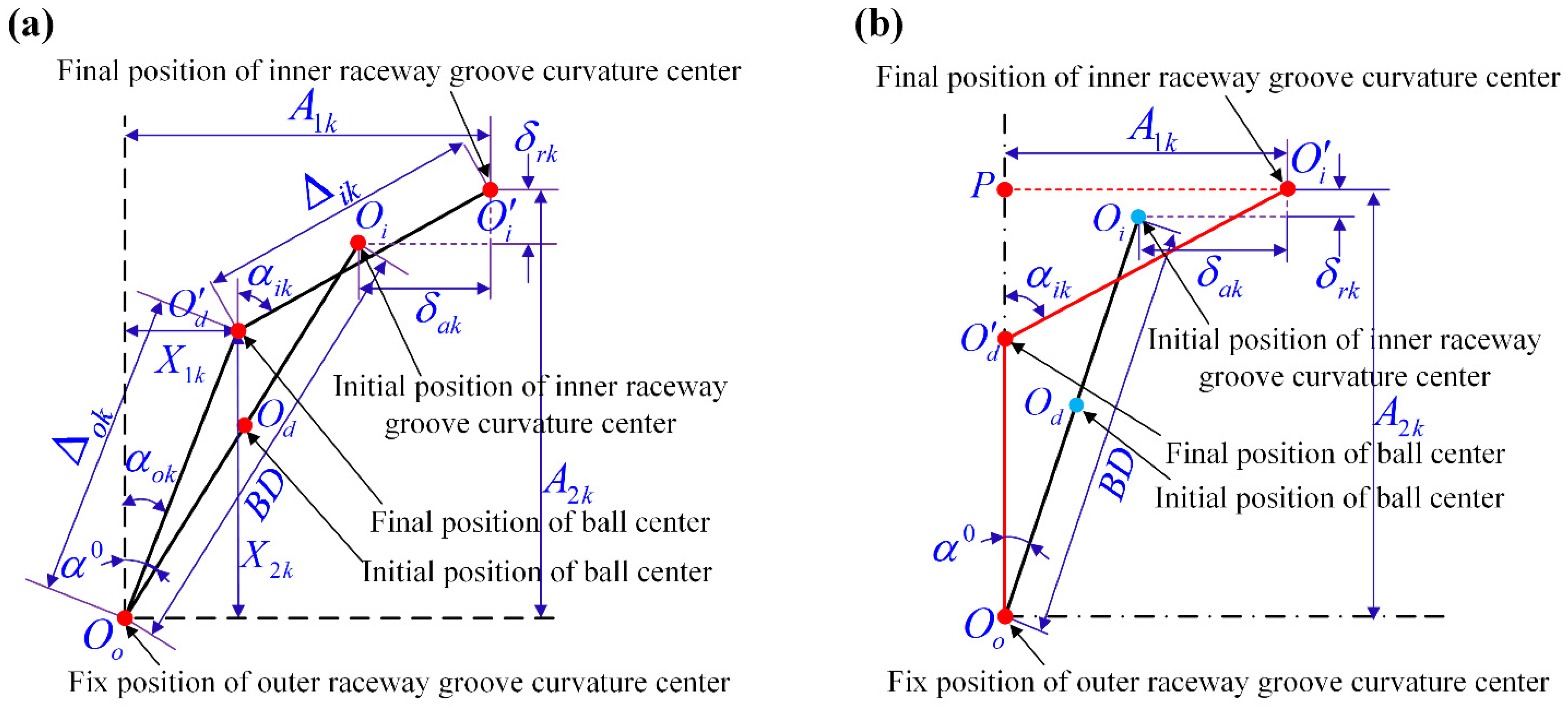
It is assumed that the bearing is acted by a combined external load vector F = {Fx, Fy, Fz, My, Mz}, and the relative displacement vector between the inner and outer rings is d = { δ x , δ y , δ z , θ y , θ z }. Assuming that the rotating speed of inner ring is ω i . It can be seen from Figure 2a that the position of ball center moves upward due to the ball centrifugal force. Consequently, the contact angle between the inner raceway and ball increases, while the contact angle between the outer raceway and ball decreases. It should be noticed that the above analysis is only applicable to the ball–raceway contact situation, but when ball bearing is acted by the combined loads with a small axial force, parts of balls may no longer be loaded, and the bearing is divided into two parts: the loaded zone and the unloaded zone [45]. It can be seen from Figure 2b that parts of the balls are separate from the inner raceway by the action of centrifugal force. However, this phenomenon is usually ignored in modeling and stiffness calculation of ball bearing under the action of combined loads.
It also can be seen from Figure 2a that the expressions for the sine and cosine functions of the ball–raceways contact angles of ball in loaded zone are written as:
{ sin α i k = A 1 k X 1 k r i 0.5 D + δ i k cos α i k = A 2 k X 2 k r i 0.5 D + δ i k sin α o k = X 1 k r o 0.5 D + δ o k cos α o k = X 2 k r o 0.5 D + δ o k
where ri, ro denote the inner/outer raceway curvature radii, respectively. The curvature centers distances of the inner and outer raceways at angular position ψ k can be written:
{ A 1 k = B D sin α 0 + 5 d m θ y sin ψ k 0.5 d m θ z cos ψ k A 2 k = B D cos α 0 + δ y cos ψ k + δ z sin ψ k
where D and dm are the dimeter of ball and the pitch radius of ball bearing, respectively. Besides, the geometry equilibrium equations can also be obtained according to Figure 2a:
{ E q 1 k = A 1 k Δ i k sin α i k Δ o k sin α o k = 0 E q 2 k = A 2 k Δ i k cos α i k Δ o k cos α o k = 0
It can be seen from Figure 2b, when the ball–inner raceway separation occurs, that the center distance between the outer raceway curvature and ball is expressed [46]:
O o O d ¯ = ( f o 0.5 ) D + δ o k
In addition, since the ball is not restrained by the inner ring, the following inequality about the center’s distance between the inner ring curvature and ball needs to be satisfied [46]:
O i O d ¯ = ( P O d ¯ ) 2 + ( P O i ¯ ) 2 ( f o 0.5 ) D
where the distances P O d ¯ and P O i ¯ can be written as:
{ P O d ¯ = A 2 k [ ( f o 0.5 ) D + δ o k ] P O i ¯ = A 1 k
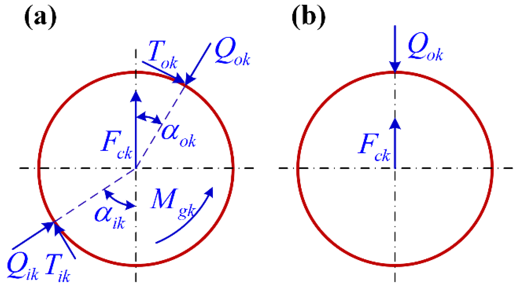
when the ball is located in the loaded zone, the mechanical equilibrium equations of ball are expressed as:
{ E q 3 k = Q i k sin α i k Q o k sin α o k T i k cos α i k + T o k cos α o k = 0 E q 4 k = Q i k cos α i k Q o k c o s α o k T i k sin α i k + T o k sin α o k + F c k = 0
where Qik and Qok are the ball–inner/outer raceway contact loads, respectively. Tik and Tok are the ball–inner/outer frictions, respectively.
{ Q i k = K i k δ i k 3 2 Q o k = K o k δ o k 3 2 T i k = λ i k M g k D T o k = λ o k M g k D
In the above equations, the Kik and Kok are the load-deformation coefficients in ball–raceways contacts, the values of Kik and Kok are determined by the basic structural parameters and the contact angles, and the analytical calculation expressions Kik and Kok are given in Appendix A. δ i k and δ o k are the elastic deformations of ball–raceway contacts. In addition, according to the Raceway Control Theory of Jones, λ i k = 0 and λ o k = 2 are used in “Outer Raceway Control Hypothesis” and λ i k = 1 , λ o k = 1 are used in “Inner Raceway Control Hypothesis”. However, a lot of research show that the Inner and Outer Raceway Control Hypothesis shows a speed-discontinuity in bearing analysis and the “Raceway Control Hypothesis” is only suitable for the analysis of ball bearing under some specific conditions [6]. In order to overcome the above shortcomings, λ i k = 2 Q i k Q i k + Q o k and λ o k = 2 Q o k Q i k + Q o k can be selected according to equal friction coefficient assumption [8]. Besides, the inertia forces, including the gyroscopic moment M g k and the centrifugal force F c k of ball, are expressed:
{ F c k = 0.5 m d m ω m k 2 M g k = J ω m k ω b k sin β k
where m and J denote the mass and the mass moment of ball. ω m k and ω b k are the revolution and spin angular speeds of ball, respectively [9], ω m k and ω b k can be written:
{ ω m k = ω i ( 1 γ i k ) cos ( α o k β k ) ( 1 + γ o k ) cos ( α i k β k ) + ( 1 γ i k ) cos ( α o k β k ) ω b k = d m D ω i ( 1 γ i k ) ( 1 + γ o k ) ( 1 + γ o k ) cos ( α i k β k ) + ( 1 γ i k ) cos ( α o k β k )
where γ i k = D cos α i k d m and γ o k = D cos α o k d m , and the pitch angle β k are given based on the d’Alembert principle [9]:
t a n β k = M ( N + 1 ) sin α i k + 2 sin α o k M ( N + 1 ) cos α i k + 2 ( cos α o k + D d m ) + G
with
{ M = Q i k a i k L i k Q o k a o k L o k G = D d m M [ cos ( α i k α o k ) N ] N = 1 + D d m cos α o k 1 cos α i k
where a i k and a o k the semi-major axes of the ball–raceways contacts. L i k and L o k are the second kind elliptic integrals of the ball–raceways contacts [9].
Besides, it can be seen from Figure 3b, if the ball separates from the inner raceway, the force equilibrium equation of ball is given as:
E q 4 k = Q o k F c k = 0
Through the above analysis, it can be found that the ball in the loaded zone has 4 unknown variables ε k = { X 1 k , X 2 k , δ i k , δ o k } in Equations (2) and (3). The Newton–Raphson algorithm has been used to calculate these variables for a given global displacement value vector d = { δ x , δ y , δ z , θ y , θ z }. In addition, it can be seen from Equation (14) that only one variable δ o k is used to describe the force state of ball in the unloaded zone. However, it needs to be noted that the inequality (5) should be calculated first in the calculation of ball local equations. If the inequality (5) holds, Equation (14) is solved, or Equations (2) and (3) are solved.
Based on the above analysis of local balls, the equilibrium relations between the external load vector F and the displacement vector d can be determined, and the mechanical equilibrium equations for rotating inner ring are given:
[ F x F y F z M y M z ] = 1 Z G [ δ i k ] { [ 1 0 0 cos ψ k 0 sin ψ k d m 2 sin ψ k 0 d m 2 cos ψ k 0 ] × [ Q i k sin α i k T i k cos α i k Q i k cos α i k + T i k sin α i k ] }
where G [ ] is the Heavisde function, it can be expressed as:
G [ δ i k ] = { 1 O i O d ¯ > r o 0.5 D 0 O i O d ¯ r o 0.5 D
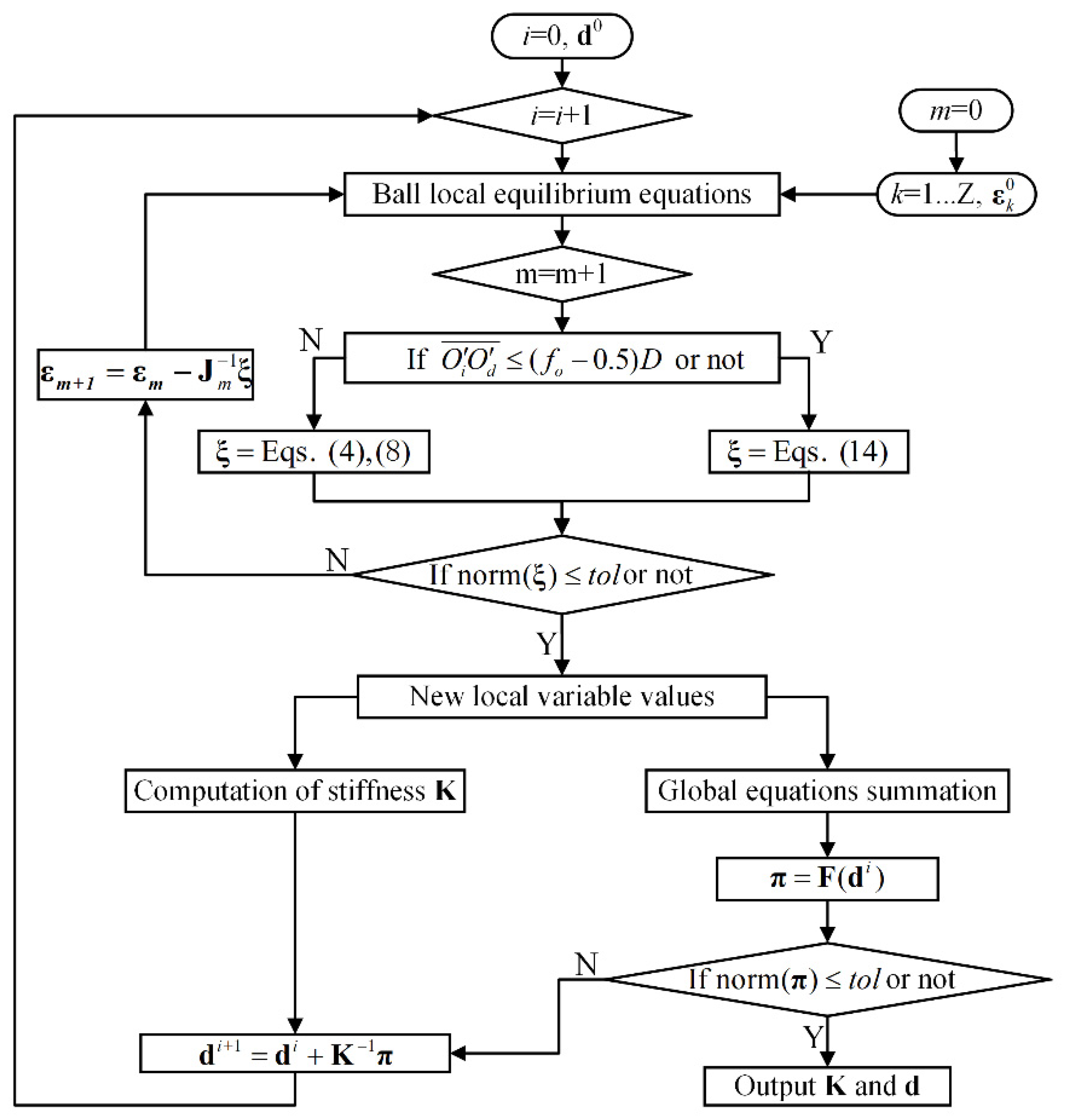
In order to calculate the global displacement for a given external load, the nested-loop Newton–Raphson iteration algorithm is used as shown in Figure 4. Firstly, input the initial iteration values of inner displacement vector d and local variables ε k = { X 1 k , X 2 k , δ i k , δ o k }; Secondly, solve the local equilibrium equations update the values of local variables and ball–raceway contact condition; Then, substitute new local variables into the global equations of inner ring and update the values of global displacements; Repeat the above iteration until the calculation errors are less than the set threshold. Finally, output the variable values and stiffness matrix. In order to complete the above iteration process, the expressions of Jm in inner iteration and stiffness matrix K in outer loop iteration need to be determined, and the matrix Jm denotes the Jacobian matrix of the ball local equations to ball local variables ε k = { X 1 k , X 2 k , δ i k , δ o k }. The detailed expressions are given as follows:
J m = [ E q 1 k ε k E q 2 k ε k E q 3 k ε k E q 4 k ε k ] = [ E q 1 k X 1 k E q 1 k X 2 k E q 1 k δ i k E q 1 k δ o k E q 2 k X 1 k E q 2 k X 2 k E q 2 k δ i k E q 2 k δ o k E q 3 k X 1 k E q 3 k X 2 k E q 3 k δ i k E q 3 k δ o k E q 4 k X 1 k E q 4 k X 2 k E q 4 k δ i k E q 4 k δ o k ]
For the ball in the unloaded zone, and O i O d ¯ ( f o 0.5 ) D . J m are given as follows:
J m = E q 4 k δ o k
In addition, the stiffness matrix K of ball bearing is illustrated in the subsequent chapters.

2.2. Computation of the Stiffness Matrix

The stiffness matrix of ball bearing can be calculated as Equation (19) through the partial derivatives between the load vector F to the displacement vector d:
[ K ] 5 × 5 = [ F x δ x F x δ y F x δ z F x θ y F x θ z F y δ x F y δ y F y δ z F y θ y F y θ z F z δ x F z δ y F z δ z F z θ y F z θ z M y δ x M y δ y M y δ z M y θ y M y θ z M z δ x M z δ y M z δ z M z θ y M z θ z ]
To obtain the complete expressions of the stiffness matrix, the relations between the external load vector F and global displacement vector d should be determined, the variable transfer graph is given in Ref [45]. Previous studies [45,46,47,48] show that the calculation process of the stiffness matrix should be divided into the partial derivatives of the load vector F to the intermediated variables υ k and the intermediated variables υ k to global displacement vector d. The difference is that the selection of intermediate variables υ k is not the same, and the most accomplished methods [18,23] have chosen υ k = { X 1 k , X 2 k , δ i k , δ o k , M g k , F c k } as the intermediate variables. However, this selection strategy is very complex in the calculation of the partial derivatives between υ k and d, thus different simplification schemes have been adopted that may cause a certain error in the stiffness matrix calculation. To simplify the partial derivatives of υ k with respect to d, the intermediate variables υ k = { X 1 k , X 2 k , δ i k , δ o k , A 1 k , A 2 k } have been used in the proposed method. Therefore, the stiffness matrix is written as:
[ K ] 5 × 5 = 1 Z G [ δ i k ] { [ F x k υ k F y k υ k F z k υ k M y k υ k M z k υ k ] 5 × 6 × [ υ k T δ x υ k T δ y υ k T δ z υ k T θ y υ k T θ z ] 6 × 5 }
where the partial derivatives between the loads vector F to the intermediated variables υ k can be written as:
[ F x k υ k F y k υ k F z k υ k M y k υ k M z k υ k ] 5 × 6 = [ 1 0 0 cos ψ k 0 sin ψ k d m 2 sin ψ k 0 d m 2 cos ψ k 0 ] 5 × 2 × [ Q i k υ k sin α i k T i k υ k cos α + Q i k sin α i k υ k i k T i k cos α i k υ k Q i k υ k cos α i k + T i k υ k sin α i k + Q i k cos α i k υ k + T i k sin α i k υ k ] 2 × 6
with
{ Q i k υ k = K i k υ k δ i k 3 2 + K i k [ 0 0 1.5 δ i k 1 2 0 0 0 ] Q o k υ k = K o k υ k δ o k 3 2 + K o k [ 0 0 0 1.5 δ o k 1 2 0 0 ]
In the previous literatures [18,19], in order to simplify the calculation process, the contributions of the load-deformation coefficients Kik and Kok to bearing stiffness calculation have been ignored. However, due to the apparent change of the contact angles, it may lead to a larger error when ball bearing operates at the high-speed range. Therefore, the detailed calculation expression of K i k υ k and K o k υ k is given in Appendix A.
In addition, the partial derivatives between the intermediated variables υ k = { X 1 k , X 2 k , δ i k , δ o k , A 1 k , A 2 k } to global displacement vector d is written as:
[ υ k T δ x υ k T δ y υ k T δ z υ k T θ y υ k T θ z ] 6 × 5 = [ X 1 k A 1 k X 1 k A 2 k X 2 k A 1 k X 2 k A 2 k δ i k A 1 k δ i k A 2 k δ o k A 1 k δ o k A 2 k 1 0 0 1 ] 6 × 2 × [ A 1 k δ x A 1 k δ y A 1 k δ z A 1 k θ y A 1 k θ z A 2 k δ x A 2 k δ y A 2 k δ z A 2 k θ y A 2 k θ z ] 2 × 5
where the partial derivatives A 1 k d and A 2 k d terms are calculated by the explicit differential of Equations (3) and (4). However, the relations among the ε k , A 1 k , and A 2 k are determined by Equations (2) and (3) in implicit form, so A 1 k d and A 2 k d terms can be obtained by the implicit differential method. Therefore, the detailed calculation process is given as follows:
{ A 1 k d = [ 1 0 0 d m 2 sin ψ k d m 2 cos ψ k ] A 2 k d = [ 0 cos ψ k sin ψ k 0 0 ]
X 1 k A 1 k = 1 J ( E q 1 k , E q 2 k , E q 3 k , E q 4 k ) ( A 1 k , X 2 k , δ i k , δ o k ) X 1 k A 2 k = 1 J ( E q 1 k , E q 2 k , E q 3 k , E q 4 k ) ( A 2 k , X 2 k , δ i k , δ o k ) X 2 k A 1 k = 1 J ( E q 1 k , E q 2 k , E q 3 k , E q 4 k ) ( X 1 k , A 1 k , δ i k , δ o k ) X 2 k A 2 k = 1 J ( E q 1 k , E q 2 k , E q 3 k , E q 4 k ) ( X 1 k , A 2 k , δ i k , δ o k ) δ i k A 1 k = 1 J ( E q 1 k , E q 2 k , E q 3 k , E q 4 k ) ( X 1 k , X 2 k , A 1 k , δ o k ) δ i k A 2 k = 1 J ( E q 1 k , E q 2 k , E q 3 k , E q 4 k ) ( X 1 k , X 2 k , A 2 k , δ o k ) δ o k A 1 k = 1 J ( E q 1 k , E q 2 k , E q 3 k , E q 4 k ) ( X 1 k , X 2 k , δ i k , A 1 k ) δ o k A 2 k = 1 J ( E q 1 k , E q 2 k , E q 3 k , E q 4 k ) ( X 1 k , X 2 k , δ i k , A 2 k )
where the Jacobi determinant J can be written as:
J = ( E q 1 k , E q 2 k , E q 3 k , E q 4 k ) ( X 1 k , X 2 k , δ i k , δ o k ) = det [ E q 1 k υ k ( 1 : 4 ) E q 2 k υ k ( 1 : 4 ) E q 3 k υ k ( 1 : 4 ) E q 4 k υ k ( 1 : 4 ) ]
Above all, the detailed solving process and key steps of analytical calculation of bearing stiffness matrix are given, and all the influence factors on stiffness for bearing quasi-static analysis have been considered. In addition, since the above solution is implemented by matrix operation, the calculation process is more clear and easier to program.

3. Results

On this basis, the stiffness matrix for ball bearing under arbitrary speeds and loads conditions can be calculated. In view of the actual needs for the engineering and the project, only the radial and axial stiffness are chosen as the main research objects in this paper.

3.1. Comparison against Experimental and Theoretical Results

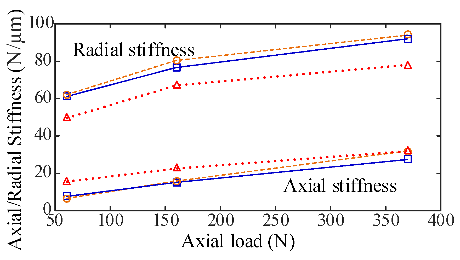
To show the effectiveness of the presented model, the calculation results of the high-precision ball bearings 7008C were compared to the results obtained by the most representative methods [18] at first. Then the static stiffness results for high-precision ball bearings 7008C and 7014C were compared against the experimental values in bearing user manual. At last, the dynamic stiffness results of bearing EEB3-2Z at 1000 rpm were compared against the published experimental and FEM results. As shown in Table 1, the key structural parameters of the above ball bearings are given.
It can be seen from Figure 5 that the contrast results of the bearing stiffness vary with the speed calculated by the proposed model and the Cao–Jones model given. It can be found that the stiffness values obtained by the proposed model are located between the stiffness values calculated by the Cao–Jones model with the “Inner/Outer Raceway Control Hypothesis”. As the “Raceway Control Theory” is based on extreme conditions, the results obtained by the proposed model are more reasonable and logical.
Then, as shown in Table 2, the comparison results of static stiffness between the proposed model and user manual values are given. One can find that the values of stiffness obtained by the proposed model are slightly more than the experimental values in bearing user manual, and it may be caused by the improvement of material properties as the special technology and heat-treatment are not considered in the model calculation.
Figure 6 gives the comparison results of the dynamic stiffness for bearing EEB3-2Z obtained by different theoretical methods and experimental analysis. It can be found that the results given by the proposed method are more consistent with the experimental results.

3.2. Stiffness Variation with Rotating Speed and Axial Preload

For the precision and high-speed ball bearing, a proper axial preload can be used to improve the rotating accuracy and supporting rigidity of ball bearing. According to Figure 7, when ball bearing is acted by a certain axial preload, the stiffness change with the rotating speed can be divided into three stages: decline slowly—drop rapidly—trend to gentle, and the same change rules have been found in previous theoretical analyses and experimental studies [34,43,44]. Besides, the decreasing trend of bearing stiffness with rotating speed has been eased. Figure 7 also gives the results of the stiffness change with the preload of ball at different speeds, and the drastic improvement of the stiffness due to the increase in the preload is presented.

3.3. Stiffness Variation with Different Load Conditions

As mentioned earlier, the ball–raceway contact analysis has been added in the bearing modeling to realize the stiffness calculation of ball bearing under arbitrary load. Therefore, to show the generality of the proposed model, three typical operation conditions of ball bearing SKF 6205 have been given to investigate the effects of the rotating speeds, the external load conditions, and the internal contact states of balls and raceways on bearing stiffness.

3.3.1. The Pure Radial Load Condition

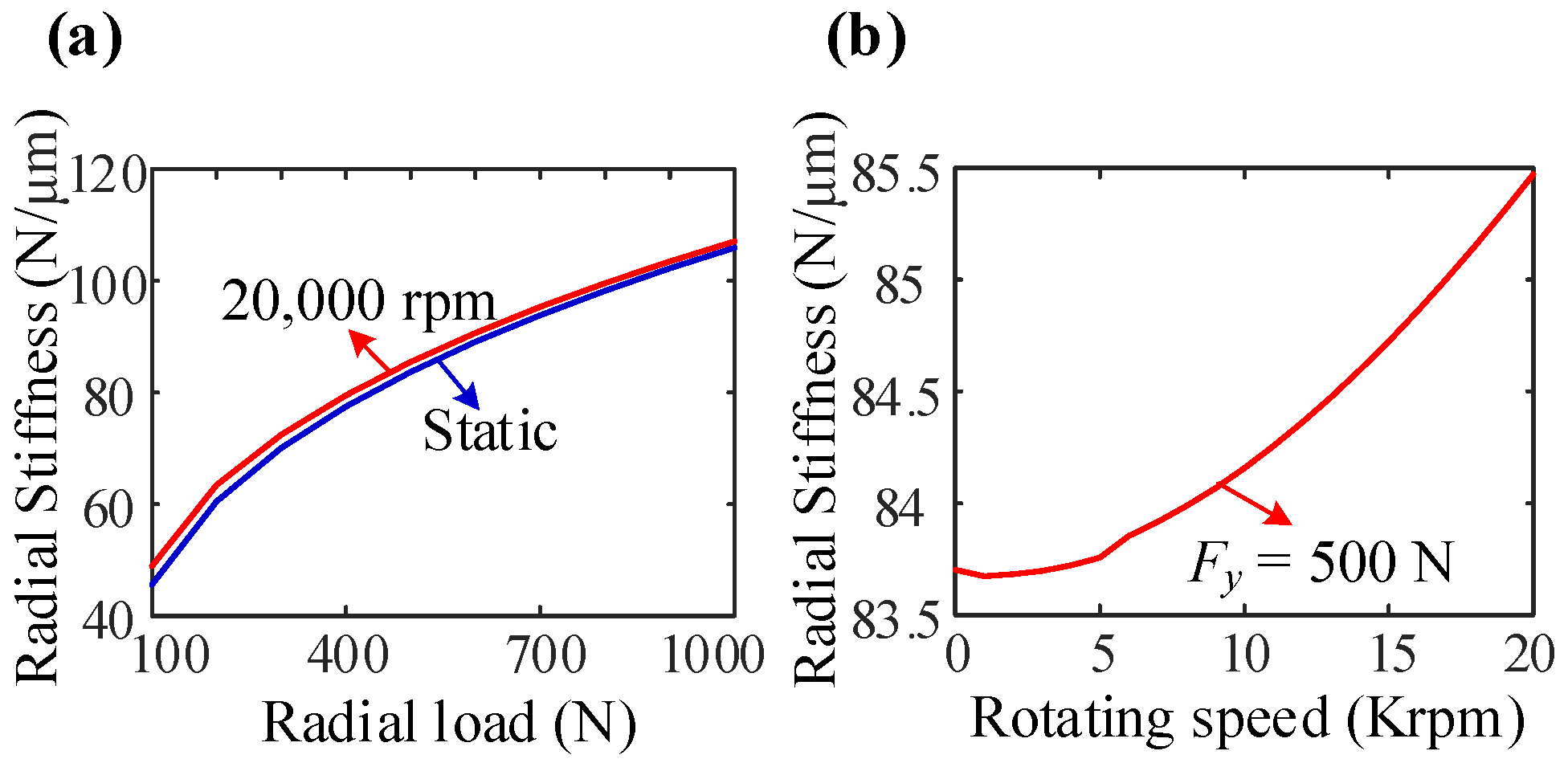
Figure 8 gives the stiffness change curves of ball bearing under one-direction radial load. One can find that both static and dynamic stiffness increase with the radial load. Besides, different from ball bearing acted by the axial load (Preload), the stiffness of ball bearing under a certain radial load (500 N) increases with the rotating speed.

3.3.2. The Combined Large Axial Load and Small Radial Load Condition

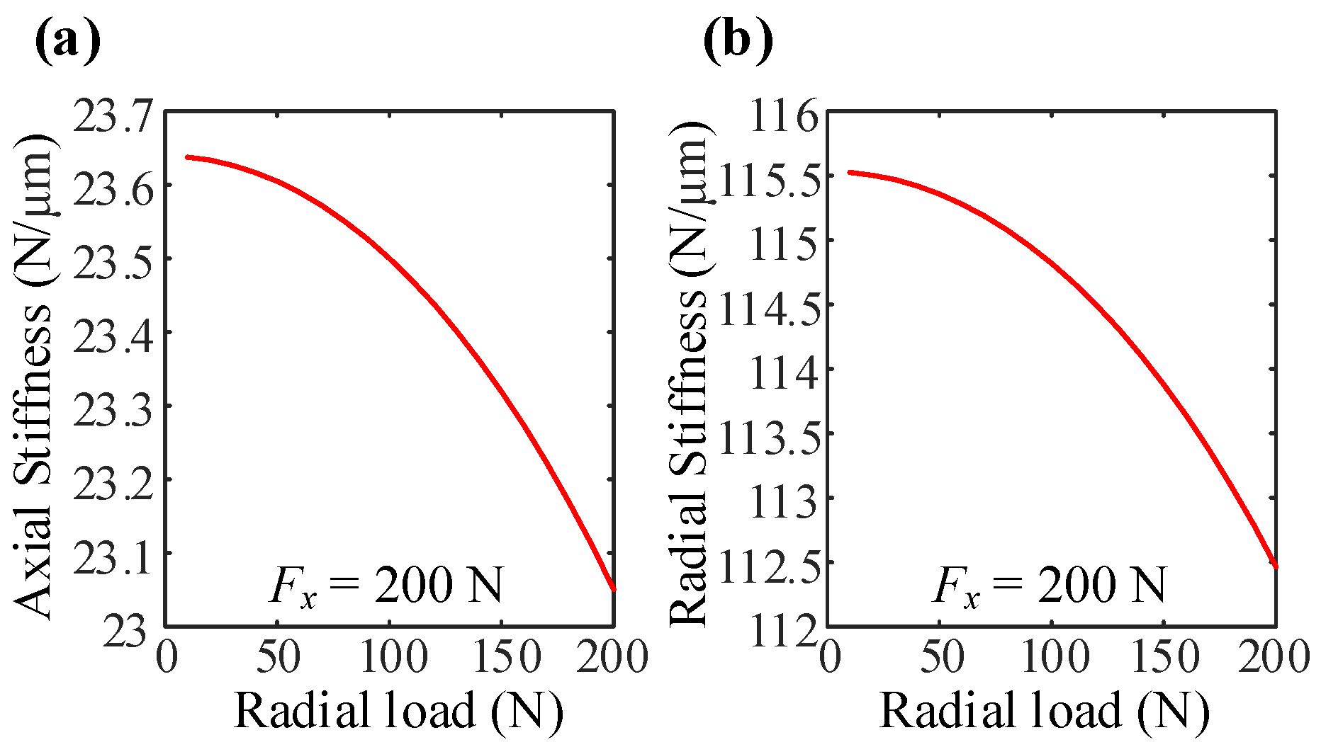
The above section has introduced the change law of ball bearing under the single direction load. On this basis, the stiffness change curves of bearing acted by the combined large axial load and small radial load at 2000 rpm are shown in Figure 9. According to the actual loading condition of ball bearing under operation condition, the angle displacement and θ y and θ z are set to zero. It can be seen from Figure 9 that both axial and radial stiffness decrease with the radial load.

3.3.3. The Combined Small Axial Load and Large Radial Load Condition

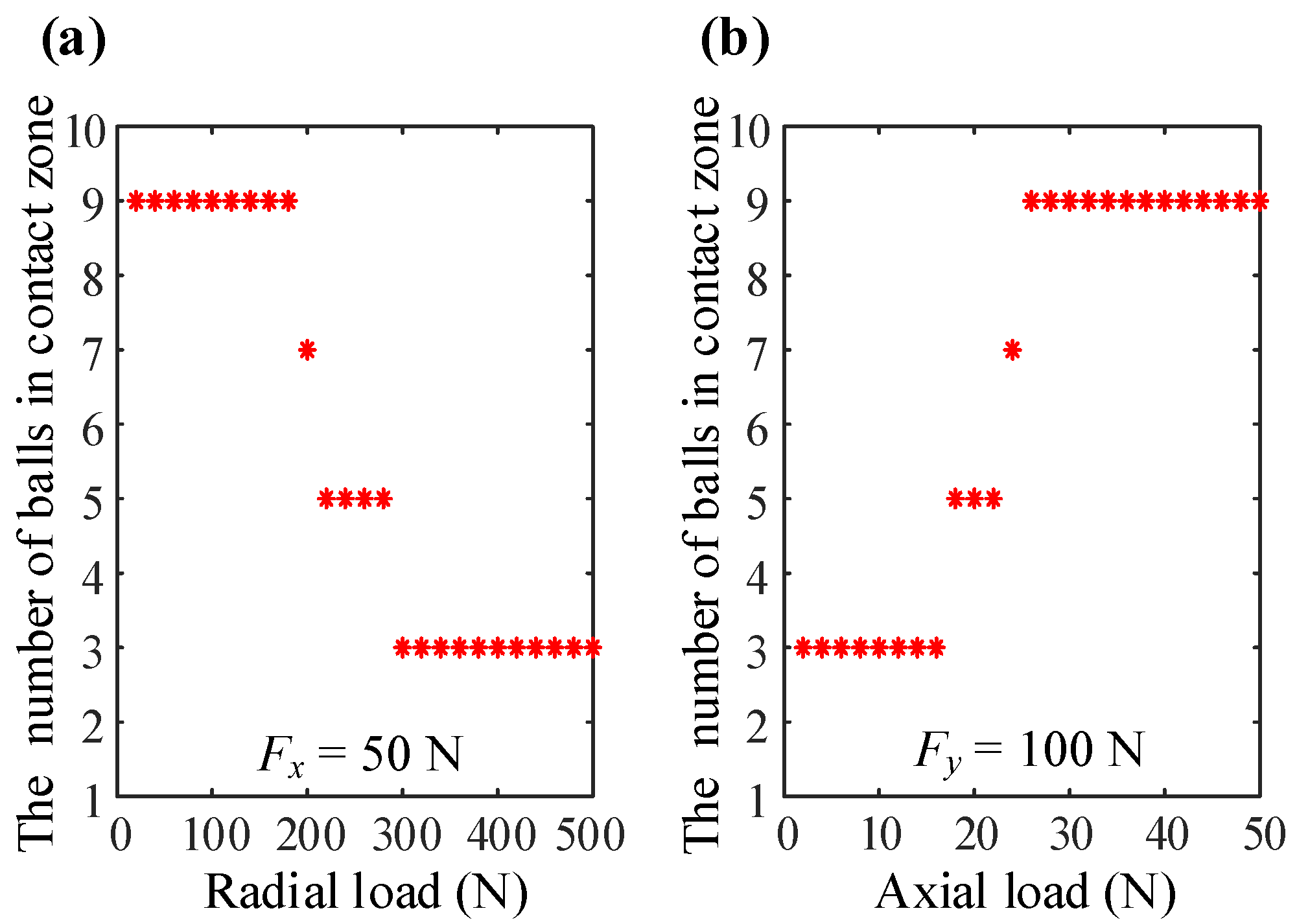
For contrast, the change curves of bearing stiffness acted by the combined small axial load and large radial load at 2000 rpm are shown in Figure 10. One can find that the axial stiffness reduces sharply with the radial load for a given axial load (50 N), and the radial stiffness firstly drops and then rises with the radial load. Besides, both the radial and axial stiffness increase with the axial load for ball bearing under a certain radial load (100 N). Different from the uniform increasing trend of axial stiffness with the axial load, the change curve of the radial stiffness contains two main pieces: the gradually increasing stage and the rapidly increasing stage. Compared with the change rule of bearing stiffness in Figure 9, the stiffness various in Figure 10 presents the diversity and complexity. In order to further reveal internal formation mechanism, the corresponding contact state between balls and raceways for ball bearing acted by the combined small axial load and large radial load are presented. As described in Figure 11a, the balls number in the loaded zone gradually decreases with the radial load. It should be noticed that, as the ball–raceway contact state change from full balls contact to partial balls contact, the change trend of bearing stiffness also changes. The axial stiffness changes from slow decline to rapid decline and the radial stiffness changes from decline to rising. In addition, as seen from Figure 11b, for the given radial load, the number of balls located at the loaded zone gradually increases with the axial load. Looking back at Figure 10, it can be found that the increasing trend of ball radial stiffness with axial load changes from slow rising to rapid rising when the ball–raceway contact state changes from partial balls contact to full balls contact. Above all, combining Figure 10 and Figure 11, one can find that the changing trend of the stiffness for ball bearing in full balls contact condition is the same as the results in Figure 9, and the changing trend of bearing stiffness depends on the change of the internal contact state between balls and raceways. Therefore, one can conclude that the ball–raceway contact state has significant influence on the variation of bearing stiffness.

3.4. Stiffness Change with Internal Structural Parameters

In the above sections, the influence of operation conditions (speed and loads) on bearing stiffness has been described in detail. Due to the bearing internal structural parameter also having importance on bearing stiffness, in the following chapter, the high-precision ball bearing 7008C is a case to discuss the influences of the various structural parameters on the stiffness.
As an important design parameter, the initial contact angle has great effects on the dynamic characteristic for ball bearings at high-speed range. The size of the initial contact angle can be adjusted as Equation (27) through changing internal structural parameters, including ri (fi), ro (fo), D, di, and do:
cos α 0 = 1 P d 2 A ,   P d = d o d i 2 D     A = r o + r i D
where P d denotes the internal radial clearance.
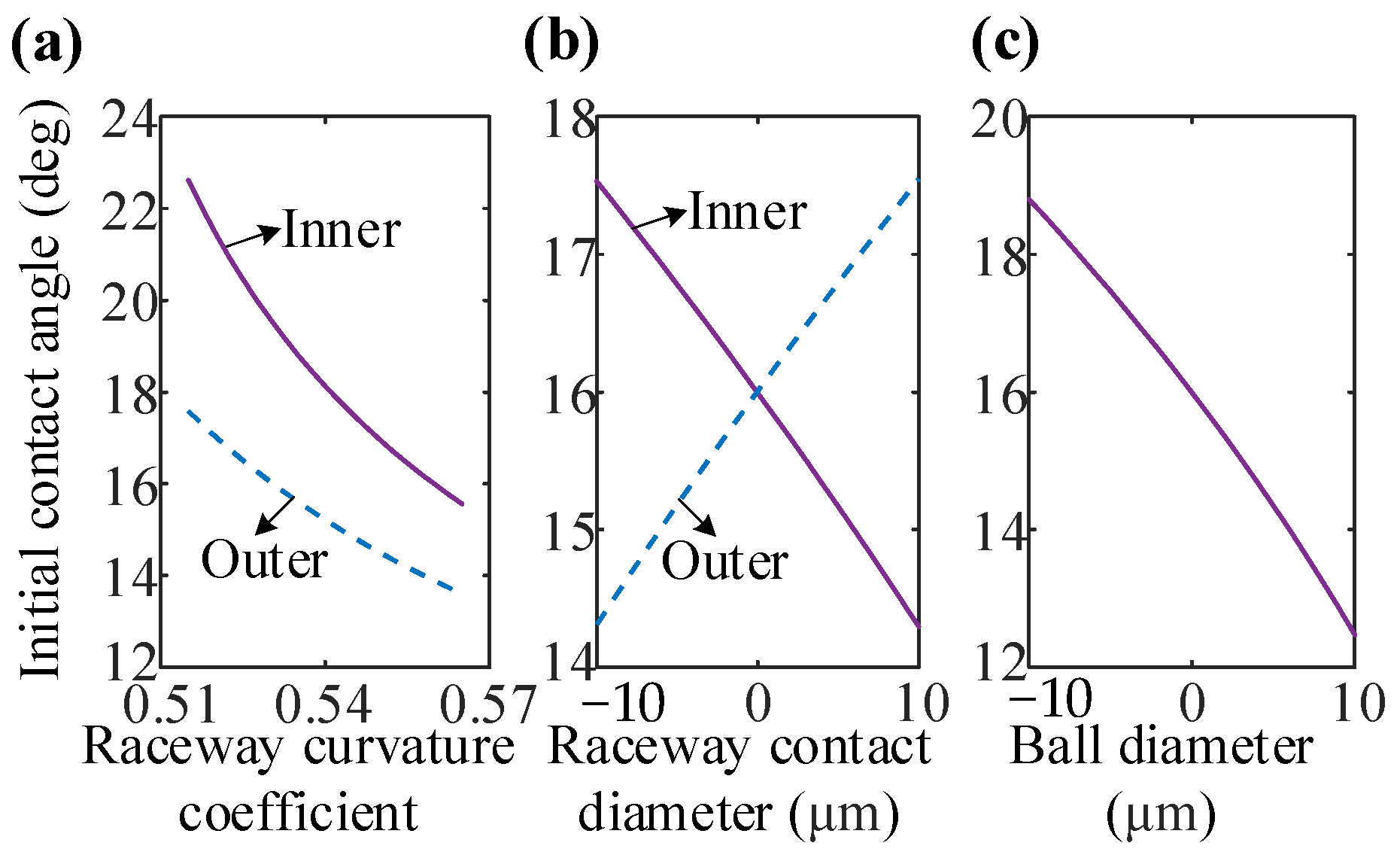
It can be seen from Figure 12 that the influence rule of internal structural parameters variations on bearing initial contact angle is given. One can find that the initial contact angle decreases with the curvature center’s distance between inner and outer raceways (both ri (fi) and ro (fo) increase). Besides, the initial contact angle increases with the radial clearance (di decreases, do increases, and D decreases).
f i = r i D ,   f o = r o D

3.4.1. Single Structural Parameter Variation

In order to reveal the influence rules of single structural parameter variation on bearing stiffness under different speeds, the precision angular contact ball bearing 7008C under medium preload (290 N) has been chosen as the calculation example, and the key structural parameters are shown in Table 1. On this basis, the detailed calculation results are given in Figure 13, Figure 14 and Figure 15.
Figure 13 illustrates the influence of groove curvature coefficient (radius) variation on bearing stiffness under different speeds. It can be seen from Figure 13a,b that, for ball bearing at a static state or low speed, the axial stiffness decreases and radial stiffness remains basically unchanged with the rise of the curvature coefficient (radius) of inner raceway. Besides, when bearing under high-speed range, both the radial and axial stiffness increase with the curvature coefficient of inner raceway. Besides, it can be seen from Figure 13c,d that both the radial and axial stiffness decrease with the curvature radius of the outer raceway for the bearing at any speeds.
According to Figure 12, the size of the initial contact angle increases with the decrease of ri (fi) or ro (fo). Generally, for bearing at static state, the axial stiffness increases and radial stiffness decreases against the initial contact angle. However, for the raceway curvature coefficients variation, the change rule of bearing stiffness and contact angle is slightly different. Combining Figure 12 and Figure 13, one can find that the radial stiffness basically remains unchanged with the changes of initial contact angle and raceway curvature coefficient. It is caused from, with the decrease of raceway curvature coefficient, the contact surfaces between ball and raceways becoming more fit and contact stiffness increasing, thus suppressing the decrease of bearing radial stiffness. However, for bearing at high speed, with the decrease of inner raceway curvature coefficient, radial stiffness decreases rapidly. With the decrease of outer raceway curvature coefficient, both radial and axial stiffness increase rapidly. It is caused by that the contact forces among balls and outer raceways increase rapidly as the rotating speed rise, and the sizes of bearing stiffness mainly depend on the contact angle and contact stiffness of ball–outer raceway that increases rapidly with the decrease of the curvature coefficient of outer raceway. Therefore, when ball bearing runs at high-speed range, when the outer raceway curvature coefficient decreases, both axial and radial stiffness increase rapidly.
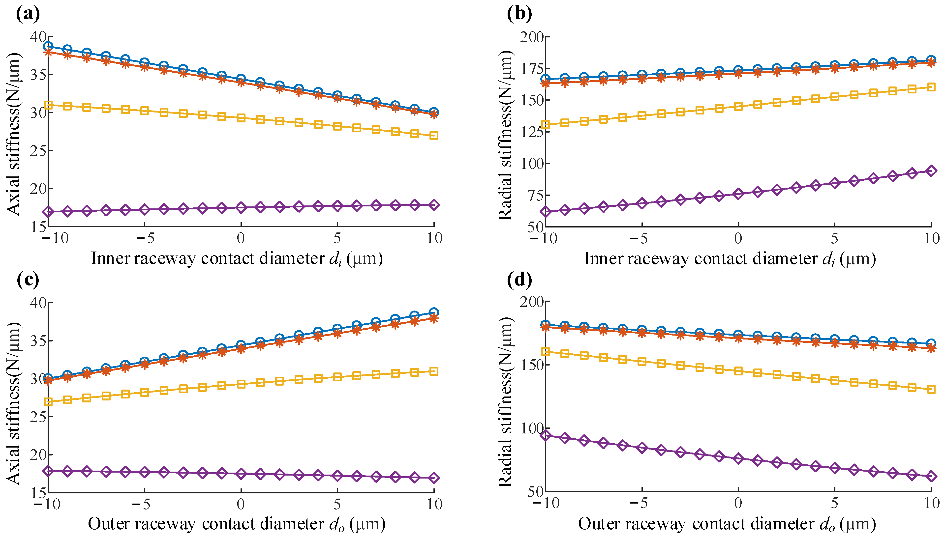
Besides, according to Equation (27) and Figure 12, one can find that the raceway contact diameters also have great influence on the initial contact angle and radial clearance of ball bearing. Figure 14 illustrates the influences of the raceway contact diameters variations on bearing stiffness under different speeds is given. With the increase of the contact diameter of inner raceway, the axial stiffness decreases and radial stiffness increases, and axial stiffness tends to be constant for the bearing at high speed. The change rule of bearing stiffness with outer raceway contact diameter variation is exactly the opposite.
In addition, the influence of the ball diameter variation on bearing stiffness under different speeds is also given in Figure 15. When the bearing is at low and medium speeds, with the increase of ball diameter, axial stiffness decreases and radial stiffness increases with the decrease of initial contact angle. When ball bearing is under the high-speed range, the axial stiffness does not decrease and slightly increases the ball diameter, it may be caused by the effect of the inertia forces of balls on the contact forces between outer raceways and balls.

3.4.2. Constant Initial Contact Angle

In the last chapter, the influences of single structural parameter variation on bearing stiffness under different speeds were described in detail. One can find that, as the internal structural parameters change, the initial contact angle is changed. However, in the actual bearing design, the initial contact angle should be a specific value, for example, the initial contact angle is about 15° for the 7008C series bearing. Therefore, the structural parameters of ball bearing are changed simultaneously to ensure a constant contact angle of the 7008C in this article research.
According to the working condition, the bearing clearance is divided into multi-levels, and the size of bearing clearance can be adjusted by changing the sizes of ball and raceway contact diameters. Without loss of generality, three different clearances, 30 µm, 50 µm, and 70 µm, are chosen, and the raceway curvature coefficients of inner and outer rings have been simultaneously changed to ensure the constant initial contact angle. It can be seen from Figure 16, for bearing at static state, with the increase of inner raceway curvature coefficient, the bearing stiffness first decreases and then increases, while for bearing at high speed, the bearing stiffness continuously increases with the curvature coefficient of the inner raceway. It means that the bearing designed with a smaller outer-raceway curvature coefficient and a larger inner-raceway curvature coefficient can improve the stiffness of ball bearing at high-speed range. Besides, with the increase of bearing clearance, both axial and radial stiffness is reduced, which means that a smaller clearance is also useful to improve the bearing stiffness. However, too small a clearance is more likely to lead to a thermal failure for ball bearing at the high-speed range.
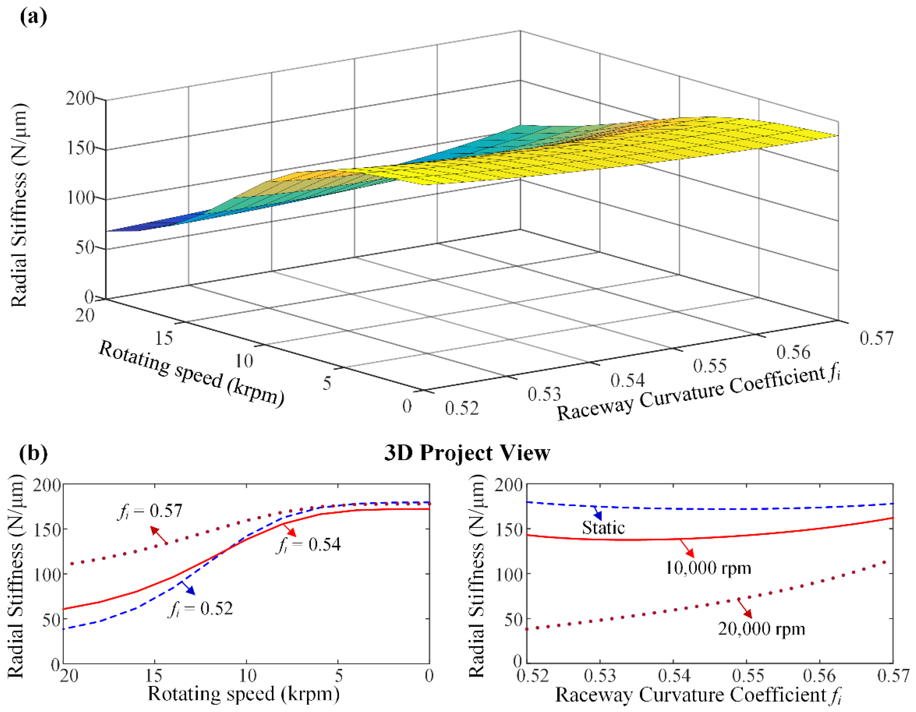
In order to further reveal the relations among the rotating speed, raceway curvature coefficient, and bearing stiffness, the three-dimension curved of the rotating speed, inner raceway curvature coefficient, and radial stiffness is given in Figure 17a. One can find that bearing stiffness gradually decreases as the rotating speed rises, and the rates of decline depend on the raceway curvature coefficient. The projection of Figure 17a,b illustrates the relation between the radial stiffness and rotating speeds of ball bearing with different raceway curvature coefficients and the radial stiffness and raceway curvature coefficients of ball bearing under different speeds, respectively. One can find that, with the increase of inner raceway curvature coefficient, the downtrend of bearing stiffness with rotating speed tends to be gentle.

4. Discussion and Conclusions

Based on the ball–raceway contact analysis, implicit/explicit differential method, and matrix operations, a comprehensive 5-DOF analytical model for stiffness matrix calculation of ball bearing under arbitrary loads condition has been proposed. Through comparison to the representative experimental and theoretical results in other literatures, the proposed model has been verified. Based on these, the influences of various operation conditions (rotating speed and loads) and structural parameters on bearing stiffness have been addressed. Some novel conclusions have been given as follows:
  • Property increasing the axial preload for ball bearing can effectively inhibit the stiffness attenuation phenomenon with rotating speed.
  • The internal contact states of balls and raceways have significant effects on the stiffness variation.
  • The influences of initial contact angle variation determined by different structure parameters on stiffness are different.
  • A smaller raceway curvature coefficient of outer ring and a larger raceway curvature coefficient of inner ring can be designed for the high-speed ball bearing range to improve its stiffness property.
This paper gives a detailed analysis of the effect factors, including the speeding speed and structure parameters on the stiffness and stiffness variations of the ball bearing under different conditions, and the conclusions drawn above can be used for ball bearing design guidance and operation and maintenance.

Author Contributions

Formal analysis, funding acquisition, writing—original draft, Q.N.; formal analysis, writing—review & editing Y.L.; conceptualization, writing—original draft, Y.Z.; data curation, software, S.P.; validation, Y.Y. and D.W. All authors have read and agreed to the published version of the manuscript.

Funding

This research was funded by National key research and development program, grant number: 2018YFB2000205.

Institutional Review Board Statement

Not applicable.

Informed Consent Statement

Not applicable.

Data Availability Statement

No date need be reported.

Conflicts of Interest

The authors declare no conflict of interest.

Nomenclature

Adistance between curvature centers of raceway groove
a i k , a o k semi-major axes of the inner and outer ball–raceways contact
Drolling ball diameter
di, docontact diameter of inner/outer raceway
dmpitch diameter
Eequivalent elastic modulus
F c k centrifugal force of the kth ball
F ¯ i k , F ¯ o k The second kind of elliptic integral of the inner and outer ball–raceways contact
f i , f o r i / D ; r o / D
Jmass moment of the ball
JJacobi determinant
J m Jacobian matrix of the ball local equations to ball local variables
K stiffness matrix
K i k ,   K o k load-deformation coefficients in the kth ball–inner/outer raceway contact
L i k , L o k the second kind elliptic integral of the inner and outer ball–raceways contact
mmass of the ball
M g k gyroscopic moment of the kth ball
P d internal radial clearance
Q i k , Q o k contact loads of the kth ball–inner/outer raceway
ri, roinner/outer raceway curvature radius
R x i k , R x o k equivalent curvature radius of the inner and outer ball–raceways contact
T i k , T o k frictions of the kth ball–inner/outer raceway
Znumber of rolling balls
α 0 initial contact angle
α i k , α o k contact angle of the kth ball
β k pitch angle of the kth ball
θ y , θ z The angular displacements of ball bearing
δ i k , δ o k elastic deformations of the kth ball–inner/outer raceway contacts
δ x , δ y , δ z elative displacement of the inner and outer rings
λ i k , λ o k the distribution factor of the contact load of the inner and outer ball–raceways contact
γ i k , γ o k D cos α i k / d m ; D cos α o k / d m
ω i rotating speed of inner ring
ω b k spin angular speed of the kth ball
ω m k revolution angular speed of the kth ball
ψ k angular position of the kth rolling ball

Appendix A. The Detailed Solution Process of Bearing Static Model

As described in the classical Hertz contact theory, the load-deflection coefficients Kik and Kok can be expressed by using the least square linear regression algorithm:
K i k = π E k ¯ i k ( R ¯ i k E ¯ i k 4.5 F ¯ i k 3 ) 1 / 2 ,   K o k = π E k ¯ o k ( R ¯ o k E ¯ o k 4.5 F ¯ o k 3 ) 1 / 2  
where E denotes the equivalent elastic modulus, and k ¯ , E ¯ , F ¯ can be expressed as follows:
k ¯ i k = 1.0339 ( R y i k R x i k ) 0.6360 ,   k ¯ o k = 1.0339 ( R y o k R x o k ) 0.6360  
E ¯ i k = 1.0003 + 0.5986 R y i k / R x i k ,   E ¯ o k = 1.0003 + 0.5986 R y o k / R x o k  
F ¯ i k = 1.5277 + 0.6023 ln ( R y i k / R x i k ) ,   F ¯ o k = 1.5277 + 0.6023 ln ( R y o k / R x o k )  
R ¯ i k = R x i k R y i k R x i k + R y i k ,   R ¯ o k = R x o k R y o k R x o k + R y o k  
The effective contact radii of the ball–inner and ball–outer raceways are written as:
R x i k = D ( d m D cos α i k ) 2 d m ,   R y i k = r i D 2 r i D  
R x o k = D ( d m + D cos α o k ) 2 d m ,   R y o k = r o D 2 r o D  

References

  1. Stribeck, R. Ball bearing for various loads. Trans. ASME 1907, 29, 420–463. [Google Scholar]
  2. Sjovall, H. The load distribution within ball and roller bearings under given external radial and axial load. Tek. Tidskr. 1933, 19, 72–75. [Google Scholar]
  3. Lundberg, G.; Palmgren, A. Dynamic Capacity of Roller Bearings. Acta Polytechnica, Generalstabens Litograf. Anst. Förl. 1952, 2, 96–127. [Google Scholar]
  4. Palmgren, A.; Ruley, B. Ball and Roller Bearing Engineering; SKF Industries, Inc.: Philadelphia, PA, USA, 1959. [Google Scholar]
  5. Jones, A.B. A general theory for elastically constrained ball and radial roller bearings under arbitrary load and speed conditions. J. Basic Eng. 1960, 82, 309–320. [Google Scholar] [CrossRef]
  6. Harris, T.A. Rolling Bearing Analysis, 3rd ed.; John Wiley & Sons: Hoboken, NJ, USA, 1991; pp. 256–296. [Google Scholar]
  7. Foord, C.A. High-speed ball bearing analysis. Proc. Inst. Mech. Eng. Part G J. Aerosp. Eng. 2006, 220, 537–544. [Google Scholar] [CrossRef]
  8. Wang, W.-Z.; Hu, L.; Zhang, S.-G.; Zhao, Z.-Q.; Ai, S. Modeling angular contact ball bearing without raceway control hypothesis. Mech. Mach. Theory 2014, 82, 154–172. [Google Scholar] [CrossRef]
  9. Ding, C.A.; Zhou, F.; Zhu, J.; Zhan, L. Raceway control assumption and the determination of rolling element attitude angle. Chin. J. Mech. Eng. En. 2001, 37, 58–61. [Google Scholar] [CrossRef]
  10. Walters, C.T. Dynamics of ball bearings. J. Lubr. Technol. 1971, 93, 1–10. [Google Scholar] [CrossRef]
  11. Gupta, P.K. Dynamics of rolling-element bearings—Part III: Ball-bearing analysis. J. Lubr. Technol. Trans. ASME 1979, 101, 312–318. [Google Scholar] [CrossRef]
  12. Gupta, P.K. Dynamics of rolling-element bearings—Part IV: Ball-bearing results. J. Lubr. Technol. Trans. ASME 1979, 101, 319–326. [Google Scholar] [CrossRef]
  13. Meeks, C.R.; Ng, K.O. The dynamics of ball separators in ball bearings—Part I: Analysis. ASLE Trans. 1985, 28, 277–287. [Google Scholar] [CrossRef]
  14. Meeks, C.R.; Long, T. Ball bearing dynamic analysis using computer methods—Part I: Analysis. J. Tribol. Trans. ASME 1996, 118, 52–58. [Google Scholar] [CrossRef]
  15. Wang, Y.; Wang, W.; Zhang, S.; Zhao, Z. Investigation of skidding in angular contact ball bearings under high speed. Tribol. Int. 2015, 92, 404–417. [Google Scholar] [CrossRef]
  16. Panda, S.; Nanda, P.; Mishra, D. Comparative study on optimum design of rolling element bearing. Tribol. Int. 2015, 92, 595–604. [Google Scholar] [CrossRef]
  17. Li, H.; Shin, Y.C. Analysis of bearing configuration effects on high speed spindles using an integrated dynamic thermo-mechanical spindle model. Int. J. Mach. Tool. Manuf. 2004, 44, 347–364. [Google Scholar] [CrossRef]
  18. Cao, Y.; Altintas, Y. A general method for the modelling of spindle-bearing systems. J. Mech. Des. Trans. ASME 2004, 126, 1089–1104. [Google Scholar] [CrossRef]
  19. Cao, H.; Holkup, T.; Altintas, Y. A comparative study on the dynamics of high speed spindles with respect to different preload mechanisms. Int. J. Adv. Manuf. Tech. 2011, 57, 871–883. [Google Scholar] [CrossRef]
  20. Gargiulo, E.P. A simple way to estimate bearing stiffness. Mach. Des. 1980, 52, 107–110. [Google Scholar]
  21. Wardle, F.P.; Lacey, S.J.; Poon, S.Y. Dynamic and static characteristics of a wide speed range machine tool spindle. Precis. Eng. 1983, 5, 175–183. [Google Scholar] [CrossRef]
  22. Houpert, L. A uniform analytical approach for ball and roller bearings calculations. J. Tribol. 1997, 119, 851–858. [Google Scholar] [CrossRef]
  23. Hernot, X.; Sartor, M.; Guillot, J. Calculation of the Stiffness Matrix of Angular Contact Ball Bearings by Using the Analytical Approach. J. Mech. Des. Trans ASME 2000, 122, 83–90. [Google Scholar] [CrossRef]
  24. Liu, J.; Tang, C.; Wu, H.; Xu, Z.; Wang, L. An analytical calculation method of the load distribution and stiffness of an angular contact ball bearing. Mech. Mach. Theory 2019, 142, 103597. [Google Scholar] [CrossRef]
  25. Lim, T.C.; Singh, R. Vibration transmission through rolling element bearings, part I: Bearing stiffness formulation. J. Sound Vib. 1990, 139, 179–199. [Google Scholar] [CrossRef]
  26. Lim, T.C.; Singh, R. Vibration transmission through rolling element bearings, part II: System studies. J. Sound Vib. 1990, 139, 201–225. [Google Scholar] [CrossRef]
  27. Lim, T.C.; Singh, R. Vibration transmission through rolling element bearings, Part III: Geared rotor system studies. J. Sound Vib. 1991, 151, 31–54. [Google Scholar] [CrossRef]
  28. Bollinger, J.G.; Geiger, G. Analysis of the static and dynamic behavior of lathe spindles. Int. J. Mach. Tool. Des. Res. 1964, 3, 193–209. [Google Scholar] [CrossRef]
  29. While, M.F. Rolling Element Bearing Vibration Transfer Characteristics: Effect of Stiffness. J. Appl. Mech. 1979, 46, 677–684. [Google Scholar] [CrossRef]
  30. Yang, Z.; Li, B.; Yu, T. Influence of structural parameters and tolerance on stiffness of high-speed ball bearings. Int. J. Precis. Eng. Man. 2016, 17, 1493–1501. [Google Scholar] [CrossRef]
  31. Yang, Z.; Chen, H.; Yu, T. Effects of rolling bearing configuration on stiffness of machine tool spindle. Proc. Inst. Mech. Eng. Part C J. Mech. Eng. Sci. 2017, 232, 775–785. [Google Scholar] [CrossRef]
  32. Noël, D.; Ritou, M.; Furet, B.; Le Loch, S. Complete Analytical Expression of the Stiffness Matrix of Angular Contact Ball Bearings. J. Tribol. Trans ASME 2013, 135, 1–8. [Google Scholar] [CrossRef]
  33. Fang, B.; Yan, K.; Hong, J.; Zhang, J. A comprehensive study on the off-diagonal coupling elements in the stiffness matrix of the angular contact ball bearing and their influence on the dynamic characteristics of the rotor system. Mech. Mach. Theory 2021, 158, 104251. [Google Scholar] [CrossRef]
  34. Sheng, X.; Li, B.; Wu, Z.; Li, H. Calculation of ball bearing speed-varying stiffness. Mech. Mach. Theory 2014, 81, 166–180. [Google Scholar] [CrossRef]
  35. Gunduz, A.; Singh, R. Stiffness matrix formulation for double row angular contact ball bearings: Analytical development and validation. J. Sound Vib. 2013, 332, 5898–5916. [Google Scholar] [CrossRef]
  36. Tsuha, N.; Cavalca, K.L. Stiffness and damping of elastohydrodynamic line contact applied to cylindrical roller bearing dynamic model. J. Sound Vib. 2020, 481, 115444. [Google Scholar] [CrossRef]
  37. Guo, Y.; Parker, R.G. Stiffness matrix calculation of rolling element bearings using a finite element/contact mechanics model. Mech. Mac. Theory 2012, 51, 32–45. [Google Scholar] [CrossRef]
  38. Zhang, X.; Han, Q.; Peng, Z.; Chu, F. Stability analysis of a rotor–bearing system with time-varying bearing stiffness due to finite number of balls and unbalanced force. J. Sound Vib. 2013, 332, 6768–6784. [Google Scholar] [CrossRef]
  39. Petersen, D.; Howard, C.; Prime, Z. Varying stiffness and load distributions in defective ball bearings: Analytical formulation and application to defect size estimation. J. Sound Vib. 2015, 337, 284–300. [Google Scholar] [CrossRef]
  40. Petersen, D.; Howard, C.; Sawalhi, N.; Ahmadi, A.M.; Singh, S. Analysis of bearing stiffness variations, contact forces and vibrations in radially loaded double row rolling element bearings with raceway defects. Mech. Syst. Signal. Processing 2015, 50–51, 139–160. [Google Scholar] [CrossRef]
  41. Kraus, J.; Blech, J.J.; Braun, S.G. In Situ Determination of Rolling Bearing Stiffness and Damping by Modal Analysis. J. Vib. Acoust. 1987, 109, 235. [Google Scholar] [CrossRef]
  42. Stone, B.J.; Walford, T. The measurement of the radial stiffness of rolling element bearings under oscillating conditions. J. Mech. Eng. Sci. 1980, 22, 175–181. [Google Scholar]
  43. Matsubara, M. Computational modelling of precision spindles supported by ball bearings. Int. J. Mach. Tools. Manuf. 1998, 28, 429–442. [Google Scholar] [CrossRef]
  44. Jedrzejewski, J.; Kwasny, W. Modelling of angular contact ball bearings and axial displacements for high-speed spindles. CIRP Ann. Manuf. Technol. 2010, 59, 377–382. [Google Scholar] [CrossRef]
  45. Zhang, J.; Fang, B.; Hong, J.; Zhu, Y. Effect of preload on ball-raceway contact state and fatigue life of angular contact ball bearing. Tribol. Int. 2017, 114, 365–372. [Google Scholar] [CrossRef]
  46. Zhang, J.; Fang, B.; Zhu, Y.; Hong, J. A comparative study and stiffness analysis of angular contact ball bearings under different preload mechanisms. Mech. Mach. Theory 2017, 115, 1–17. [Google Scholar] [CrossRef]
  47. Fang, B.; Zhang, J.; Yan, K.; Hong, J.; Wang, M.Y. A comprehensive study on the speed-varying stiffness of ball bearing under different load conditions. Mech. Mach. Theory 2019, 136, 1–13. [Google Scholar] [CrossRef]
  48. Zhang, Y.; Fang, B.; Kong, L.; Li, Y. Effect of the ring misalignment on the service characteristics of ball bearing and rotor system. Mech. Mach. Theory 2020, 151, 103889. [Google Scholar] [CrossRef]
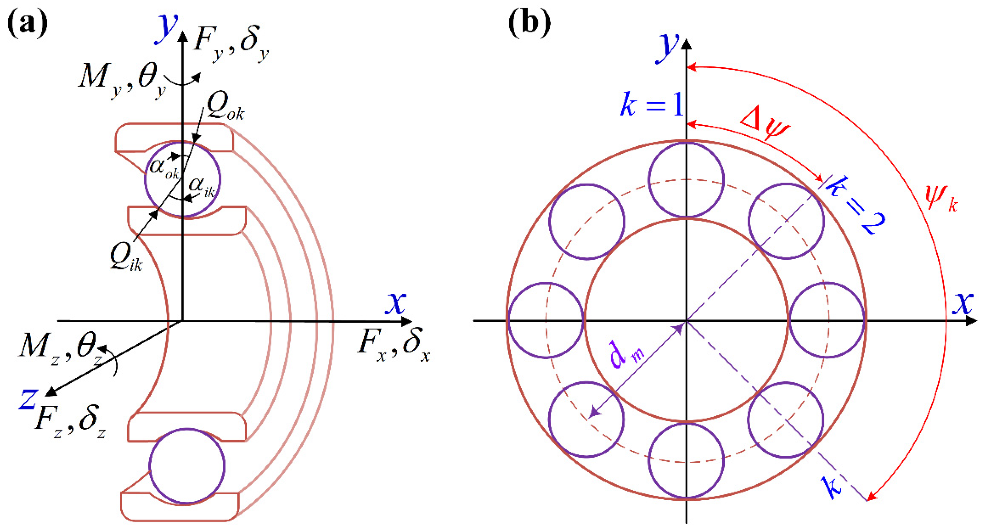
Figure 1. The coordinate systems for ball bearing: (a) Axial section and x axis coincided with the rotation center line; (b) Traverse section and ball position angle ( ψ k = 2 π ( k 1 ) / Z ).
Machines 10 00238 g001
Figure 2. The geometry relations among the centers of raceway curvature and ball: (a) The ball contacts with inner raceway; (b) The ball separates from inner raceway.
Machines 10 00238 g002
Figure 3. Force analysis of the ball, including the inertia forces (Fck, Mgk) and contact forces (Qi/ok, Ti/ok): (a) The ball contacts with inner ring; (b) The ball separates from inner ring.
Machines 10 00238 g003
Figure 4. Calculation flow of proposed model, including the internal iteration of balls and the external iteration of bearing ring.
Machines 10 00238 g004
Figure 5. Comparison of bearing stiffness varying with the speed calculated by the proposed method with Cao-Jones method with the “Inner/Outer Raceway Control Hypothesis (I/O RCH)”: (a) axial stiffness; (b) radial stiffness.
Machines 10 00238 g005
Figure 6. Comparison of the dynamic stiffness (1000 rpm) obtained by the proposed model (—□—) to the FEM results () of Guo [37] and the experiment results (--○--) of Kraus [41].
Machines 10 00238 g006
Figure 7. The influences of the rotating speed and axial preload on bearing stiffness (7008C): (a) bearing axial stiffness varies with speed and preload; (b) bearing radial stiffness varies with speed and preload.
Machines 10 00238 g007
Figure 8. The radial stiffness variation for ball bearing one-direction pure radial load: (a) the radial stiffness changes against the radial force; (b) the radial stiffness changes against the rotating speed.
Machines 10 00238 g008
Figure 9. The stiffness variation for ball bearing acted by the combined large axial load and small radial load: (a) axial stiffness varies with radial load; (b) radial stiffness varies with radial load.
Machines 10 00238 g009
Figure 10. The stiffness variation for ball bearing acted by small axial load and large radial load: (a) The axial stiffness varies against radial or axial load; (b) The radial stiffness varies against radial or axial load.
Machines 10 00238 g010
Figure 11. The contact states between balls and raceways for ball bearing acted by the small axial load and large radial load: (a) the contact states between balls and raceways varies with axial force; (b) the contact states between balls and raceways varies with radial force.
Machines 10 00238 g011
Figure 12. The influences of structural parameters on bearing initial contact angle: (a) inner/outer raceway curvature coefficients fi/o; (b) raceway contact diameters di/o; (c) ball diameter D.
Machines 10 00238 g012
Figure 13. The influences of raceway curvature coefficient on bearing stiffness: (a) bearing axial stiffness varies with inner raceway curvature coefficient fi; (b) bearing radial stiffness varies with inner raceway curvature coefficient fi; (c) bearing axial stiffness varies with outer raceway curvature coefficient fo; (d) bearing radial stiffness varies with outer raceway curvature coefficient fo (—○— rotating speed = 0 rpm, —✱— rotating speed = 5000 rpm, —□— rotating speed =10,000 rpm, —◇— rotating speed = 20,000 rpm).
Machines 10 00238 g013
Figure 14. The influences of the contact diameter of inner or outer raceway on bearing stiffness: (a) bearing axial stiffness varies with the contact diameter of inner raceway di; (b) bearing radial stiffness varies with the contact diameter of inner raceway di; (c) bearing axial stiffness varies with the contact diameter of outer raceway do; (d) bearing radial stiffness varies with the contact diameter of outer raceway do; (—○— rotating speed = 0 rpm, —✱— rotating speed = 5000 rpm, —□— rotating speed =10,000 rpm, —◇— rotating speed = 20,000 rpm).
Machines 10 00238 g014
Figure 15. The influences of ball diameter on bearing stiffness: (a) bearing axial stiffness varies with ball diameter D; (b) bearing radial stiffness varies with ball diameter D (—○— rotating speed = 0 rpm, —✱— rotating speed = 5000 rpm, —□— rotating speed =10,000 rpm, —◇— rotating speed = 20,000 rpm).
Machines 10 00238 g015
Figure 16. The influences of raceway curvature coefficient on bearing stiffness with different radial clearance and constant initial contact angle: (a) bearing axial stiffness varies with inner raceway curvature coefficient fi; (b) bearing radial stiffness varies with inner raceway curvature coefficient fi (------ rotating speed = 0 rpm, —— rotating speed = 20,000 rpm).
Machines 10 00238 g016
Figure 17. The influences of raceway curvature coefficient and rotating speed on bearing stiffness with constant initial contact angle and radial clearance: (a) the three-dimension curved of the rotating speed, inner raceway curvature coefficient, and radial stiffness; (b) the two-dimensional projection curves of three-dimensional surface (a).
Machines 10 00238 g017
Table 1. T Bearing parameters of NSK B7008C, B7014C, and SKF EEB3-2Z.
ParametersNSK
B7008C
NSK
B7014C
SKF
EEB3-2Z
SKF
6205
The curvature radius of inner raceway ri (mm)4.0005.3302.0644.108
The curvature radius of outer raceway ro (mm)3.7905.0502.0644.108
The contact diameter of inner raceway di (mm)46.83880.45211.7830.59
The contact diameter of outer raceway do (mm)61.17699.56219.7246.41
The number of internal balls Z192579
The diameter of balls D (mm)7.1449.5223.9697.900
The initial contact angle of ball bearing α 0 (°)15.99215.9426.42914.453
The pitch diameter of ball bearing dm (mm)50.0090.0015.7538.50
Table 2. The comparison of bearing static stiffness (NSK B7008C, B7014C) with the experimental values in bearing user manual (EL: extremely light; L: light; M: medium; H: heavy).
Types7008C7014C
Preload (N)60 (EL)120 (L)10he290 (M)590 (H)145 (EL)290 (L)740 (M)1470 (H)
Axial stiffness (N/µm)Model37.548.772.599.365.183.9124.4170.1
Manual3951771106888135190
error3.8%4.5%5.84%9.72%4.26%4.66%7.85%10.47%
Publisher’s Note: MDPI stays neutral with regard to jurisdictional claims in published maps and institutional affiliations.