Abstract
In this paper, we designed flat conductor winding permanent magnet synchronous motors with three different rotor structures under certain boundary conditions. The causes of the noise vibration harshness and abnormal noise of permanent magnet synchronous motors are analyzed by using an analytical method. The causes of 24-order and 48-order abnormal noise are given. Based on the comparison of the performance of three rotor structures, the V+1 rotor structure has the least no-load harmonic content, the minimum cogging torque, the maximum output torque, the lowest temperature rise, and the best motor performance, and the V+1 rotor design consumes less permanent magnet material. The simulation is verified by manufacturing a prototype, and the experimental results verify the correctness of the simulation.
1. Introduction
Different from traditional vehicles with combustion engines, the main power components of electric vehicles are the battery, motor, and electronic control. At present, the motor of electric vehicles is the one with the fastest technological innovation and the largest change.
The technical route of permanent magnet synchronous motor is changing from round wire water-cooled to round wire oil-cooled, flat wire water-cooled, or oil-cooled. At present, Tesla adopts round wire and oil-cooled permanent magnet synchronous motor, and Toyota Prius uses flat wire and oil-cooled technical route. Whether round wire or flat wire is cooled by oil, there are still extreme cases of uneven cooling and local overheating, and the overall technology is not particularly mature. The conservative view is that the current use of flat wire and the water-cooled motor is the most appropriate solution, which can ensure the improvement of power density, in addition to ensuring certain reliability [1,2].
The design of permanent magnet synchronous motors faces strong requirements such as acoustic performance, which should be assessed before the first prototypes. This characterization process needs to be integrated well into the design process. Knowing how strong a machine will vibrate beforehand allows the optimization of electromagnetic or mechanical design until the results meet the requirements. Under this background, how to decrease the vibration and noise of the motor becomes increasingly important. By optimizing the design of motor rotor structure, better motor output and vibration and noise performance can be achieved [3,4,5,6,7]. A comparative analysis of vibration and noise of different rotor structures has not been carried out in the existing literature [8,9], as many studies focus on the cause of radial force of specific rotor structures and lack the transverse comparison of different rotor structures.
In addition to the performance of the vibration and noise of the motor, the output performance is important. Compared with round wire products, the rectangular conductor used in flat wire motor has higher copper consumption and lower efficiency and temperature rise due to skin effect and proximity effect [10,11,12,13]. This paper analyzes the electromagnetic performance, noise vibration harshness, and the influence on the eddy current effect of the flat wire winding of the motor with three kinds of rotor structures: V type, V+1 type, and double-V type.
2. Motor Topology
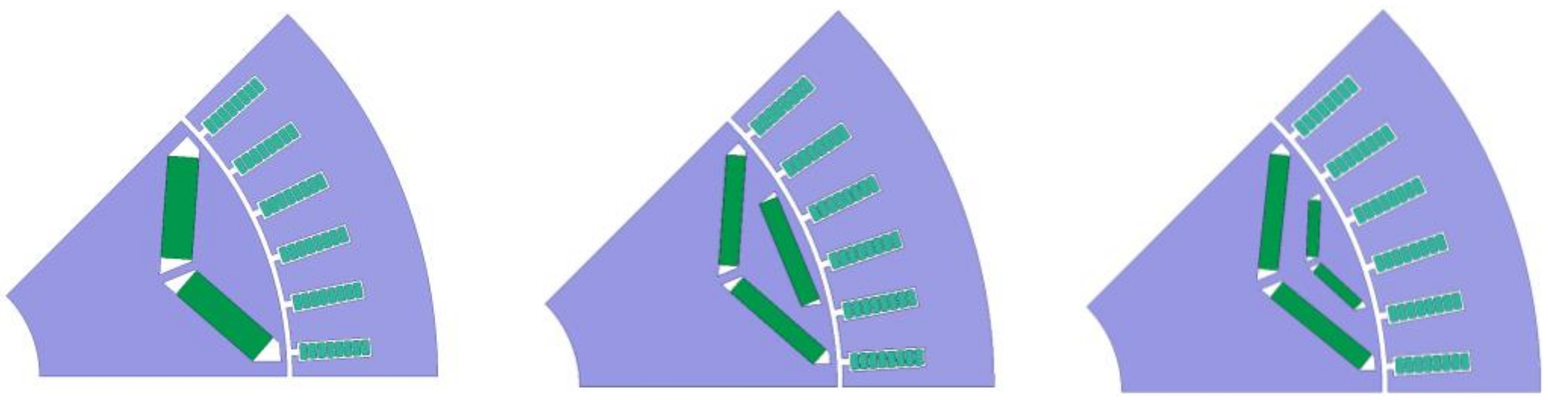
In order to study the influence of different rotor structures on the performance of permanent magnet synchronous motor, the same motor length, back EMF amplitude, and current boundary were used in the design process of the motor. The winding in the stator slots was made from flat wires with N = 8 turns. Figure 1 shows the topological structure of the motor with the V-shaped rotor, V+1-shaped rotor, and double-V-shaped rotor, respectively, and Table 1 shows the performance indexes of the three motors.

Figure 1.
Topology structure of V-shaped, V+1-shaped, and double-V-shaped rotors.

Table 1.
Units for magnetic properties.
3. Main Sources of Motor Noise Vibration Harshness Problems
The main source of motor noise vibration harshness problem for permanent magnet synchronous motor is vibration and noise, and the main source of vibration and noise is the electromagnetic force. The electromagnetic force is divided into radial electromagnetic force and tangential electromagnetic force. The radial electromagnetic force is the source of vibration and noise, and the tangential force is the source of torque ripple. The main parameters of radial electromagnetic force are the order, frequency, and amplitude of force wave Fu [14,15].
3.1. Analysis of No-Load Radial Force
The expression of no-load air gap flux density of PMSM without considering the influence of reluctance and saturation is as follows:
where b(θ,t) is the air gap flux density, f(θ,t) is the magnetomotive force, λ(θ,t) is the air gap magnetic conductance, ω1 is the fundamental angular velocity, Fu is the maximum magnetomotive force of u harmonic, u_0 is the harmonic order, p is the pole pairs, Λ0 is the air-gap fundamental magnetic conductance, Λk is the air-gap harmonic magnetic conductance, and Z1 is slot number.
When the tangential flux density is neglected, the radial force density is
where μ0 is the vacuum conductance. It can be obtained by substituting (1–3) into (4) as follows:
By decomposing the above formula, we can obtain
This calculation formula is the DC component of electromagnetic force wave, which does not change with time. The static deformation of the iron core will not cause motor vibration.
The above formula defined the radial force wave produced by the interaction of rotor magnetic field and harmonic wave.
The above formula defines the radial force wave produced by the interaction of tooth harmonic magnetic field and harmonic wave.
This calculation formula is the radial force wave generated by the interaction of different harmonics in the rotor magnetic field.
Here, Bu1 and Bu2 is the flux density of different harmonics rotor magnetic field; u1 and u2 is the harmonic order.
This calculation formula is the radial force wave generated by the interaction of different harmonics in the tooth harmonic magnetic field.
The above formula defines the radial force wave generated by the interaction of rotor magnetic field and tooth harmonic magnetic field.
3.2. Analysis of Load Radial Force
When the load is applied, a three-phase symmetrical current is applied to the three-phase winding as follows:
where υ is the harmonic number of armature winding magnetic field, considering only integer slot
The load radial force formula is: μ
Equation (14) is expanded as follows:
By decomposing Equation (15), we can obtain
where Bv1 and Bv2 are the flux density of different harmonics stator magnetic fields; v1 and v2 are the harmonic order; nu_1 and nu_2 are the variables of the sums.
This calculation formula is the electromagnetic force, which does not change with time and can only make the motor produce static deformation.
The above formula indicates the electromagnetic force wave produced by the interaction of armature magnetic field and harmonic wave.
This calculation formula defines the radial electromagnetic force wave generated by the interaction of different harmonics of armature magnetic field.
This formula is used to calculate the radial force wave generated by the interaction between the harmonic of the main pole magnetic field and the harmonic of the armature magnetic field.
The above calculation formula defines the radial force wave generated by the interaction of additional magnetic fields and armature harmonic magnetic fields.
Based on the above formulae, the number and frequency of force waves generated by permanent magnetic and armature magnetic fields are shown in Table 2. From this table, we can infer how permanent magnetic and armature magnetic fields interact with each other to form the order and frequency of electromagnetic waves.
Table 2.
Number of electromagnetic force waves and frequency.
In addition to the radial electromagnetic force waves generated by permanent magnetic and armature magnetic fields, the frequency of the radial electromagnetic force waves generated by the interaction between permanent magnetic and armature magnetic fields are shown in Table 3. From this table, we can derive the number of electromagnetic force waves and corresponding force-wave frequency when the stator and rotor magnetic fields are coupled, and the cogging effect is considered, which can reflect the electromagnetic force state of the motor during operation.
Table 3.
Number of electromagnetic force waves and frequency.
Table 4 shows the number of electromagnetic force waves generated by the main harmonics of a 48-slot, 8-pole motor. At present, problems with noise vibration harshness in vehicle motors are mainly in the orders of 24, 48, and 96 [16], and the minimum number of nonzero force waves of a 48-slot, 8-pole motor is 8, which does not contribute to the abnormal noise vibration harshness of the motor.
Table 4.
Number of electromagnetic force waves.
From the above table, it is evident that, in actual engineering applications, the sources of 24-order abnormal noise are the 5th and 7th harmonics of stator magnetic field and rotor magnetic field, while the sources of 48-order abnormal noise are the 11th and 13th harmonics.
4. Analysis of Electromagnetic Performance
4.1. Analysis of No-Load Electromagnetic Performance
4.1.1. Analysis of the Radial Air Gap Flux Density Waveform
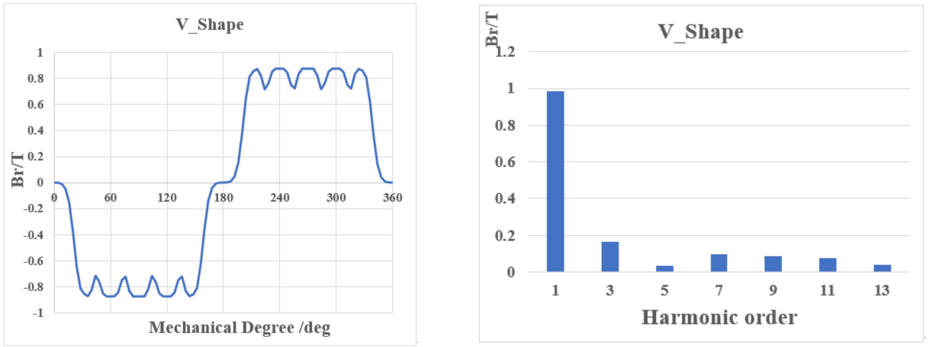
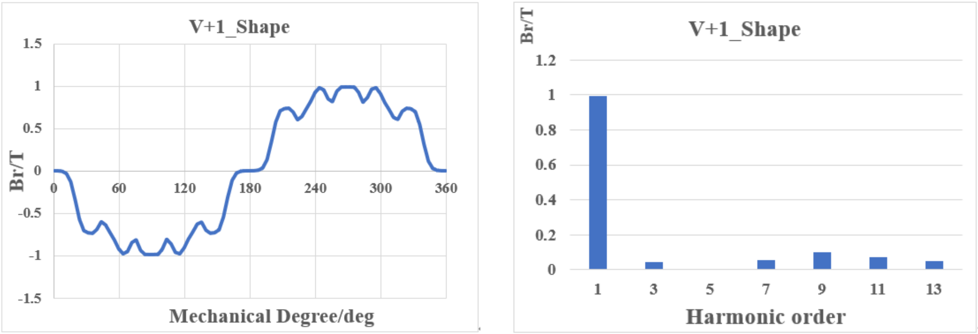
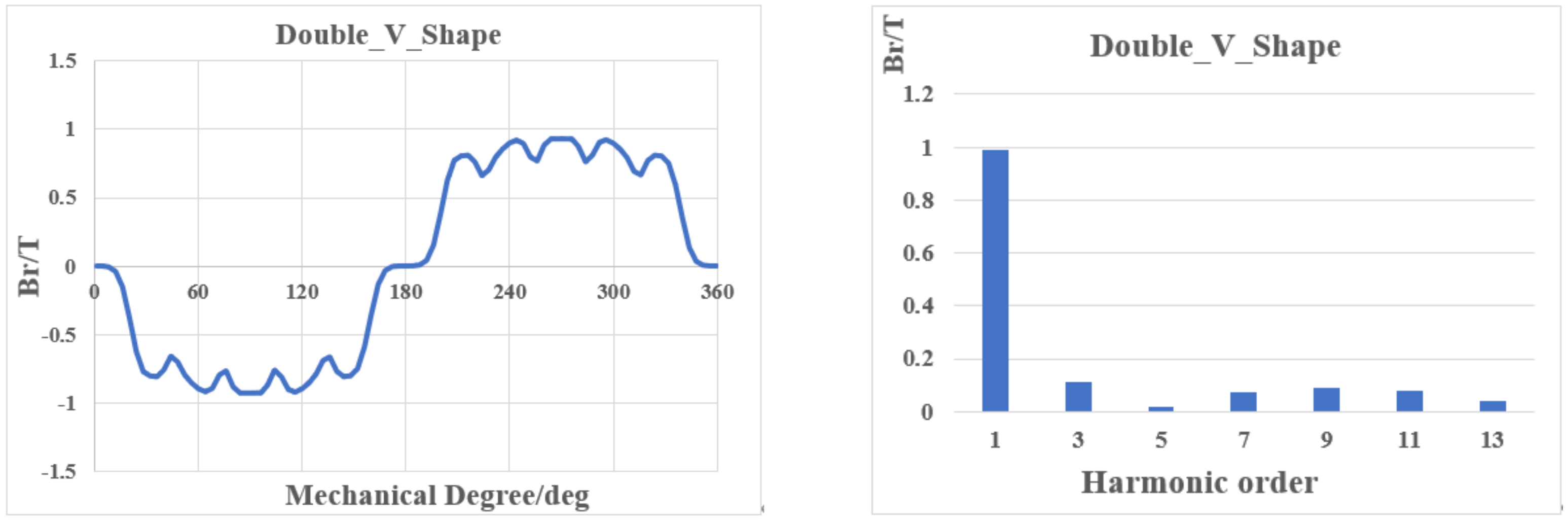
Figure 2 shows the radial air gap flux density waveform and its Fourier decomposition of the V-shaped rotor. Figure 3 and Figure 4 show the radial air-gap flux density waveform and its Fourier decomposition of V+1- and double-V-shaped topology, respectively.
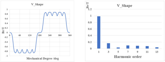
Figure 2.
Br and its FFT of V-shaped rotor.
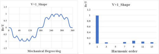
Figure 3.
Br and its FFT of V+1-shaped rotor.
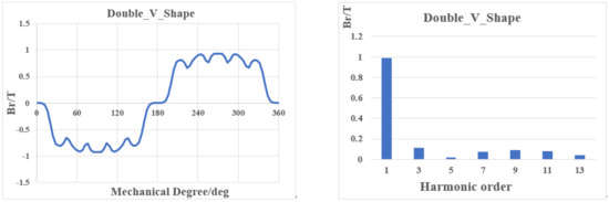
Figure 4.
Br and its FFT of double V-shaped rotor.
From Figure 2, the radial air-gap flux density waveform and its Fourier decomposition of V-shaped rotor, we can discern that the V-shaped rotor mainly contains the 3rd, 5th, 7th, 9th, 11th, and 13th harmonics, and all of the harmonic content in this type of rotor is relatively more than that of the other two types.
From Figure 3, the radial air-gap flux density waveform and its Fourier decomposition of the V+1 shaped rotor, we can discern that the V+1-shaped rotor has scarcely any fifth harmonic order. Other harmonics are smaller than those of the V-shaped rotor and double-V-shaped rotors.
From Figure 4, the radial air-gap flux density waveform and its Fourier decomposition of the double-V-shaped rotor, we can infer that the double-V-shaped rotor mainly contains the 3rd, 7th, 9th, 11th, and 13th harmonics. The 7th, 9th, 11th, and 13th harmonic content is similar to that of the V+1-shaped rotor; however, the third harmonic content is noticeably larger than that of the V+1-shaped rotor.
From the harmonic content comparison of the three motors, we can draw a general conclusion that the V+1-shaped rotor is the best-performing rotor, and the double-V-shaped rotor is the second best. The V-shaped rotor is not better than the other two types of motor.
4.1.2. Analysis of the Cogging Torque
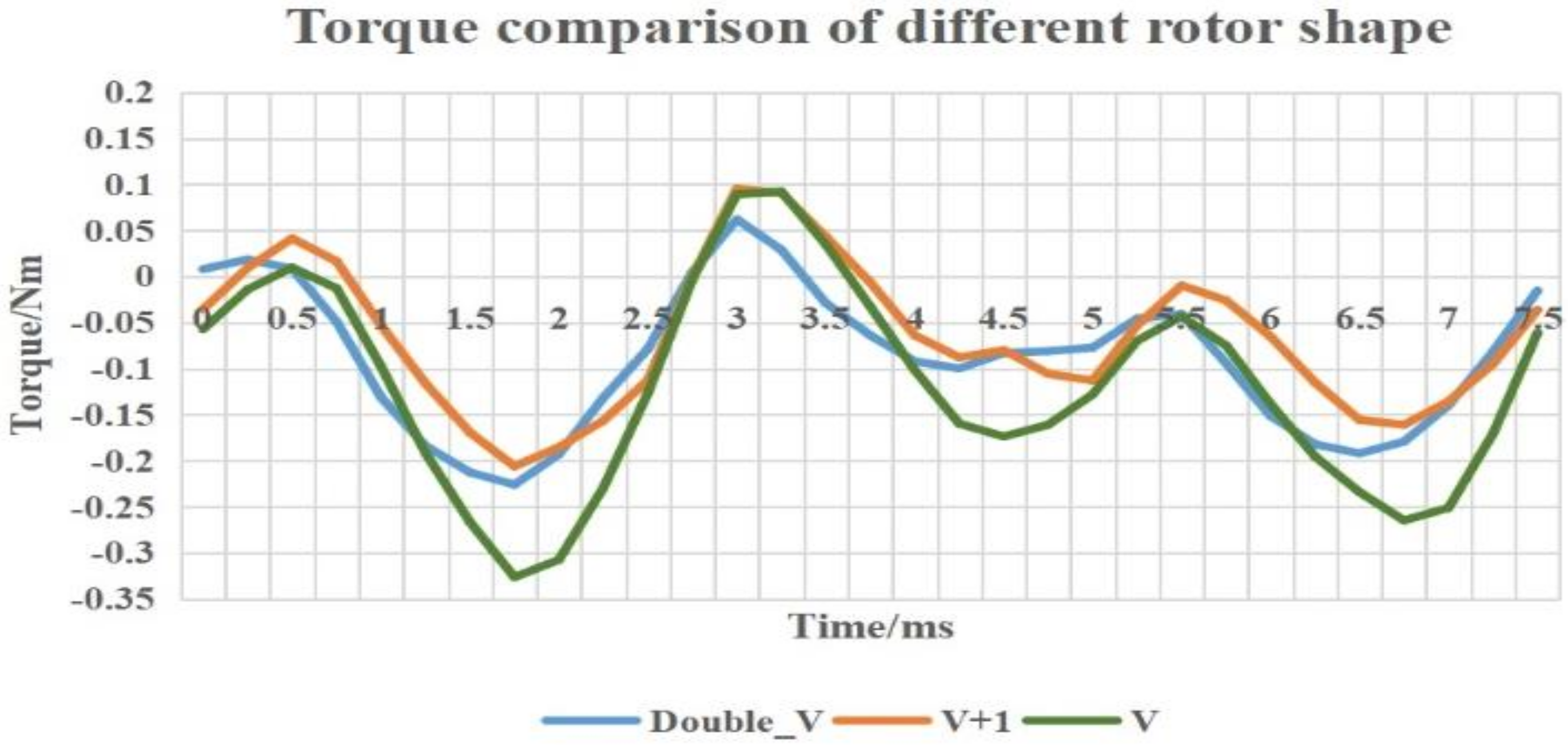
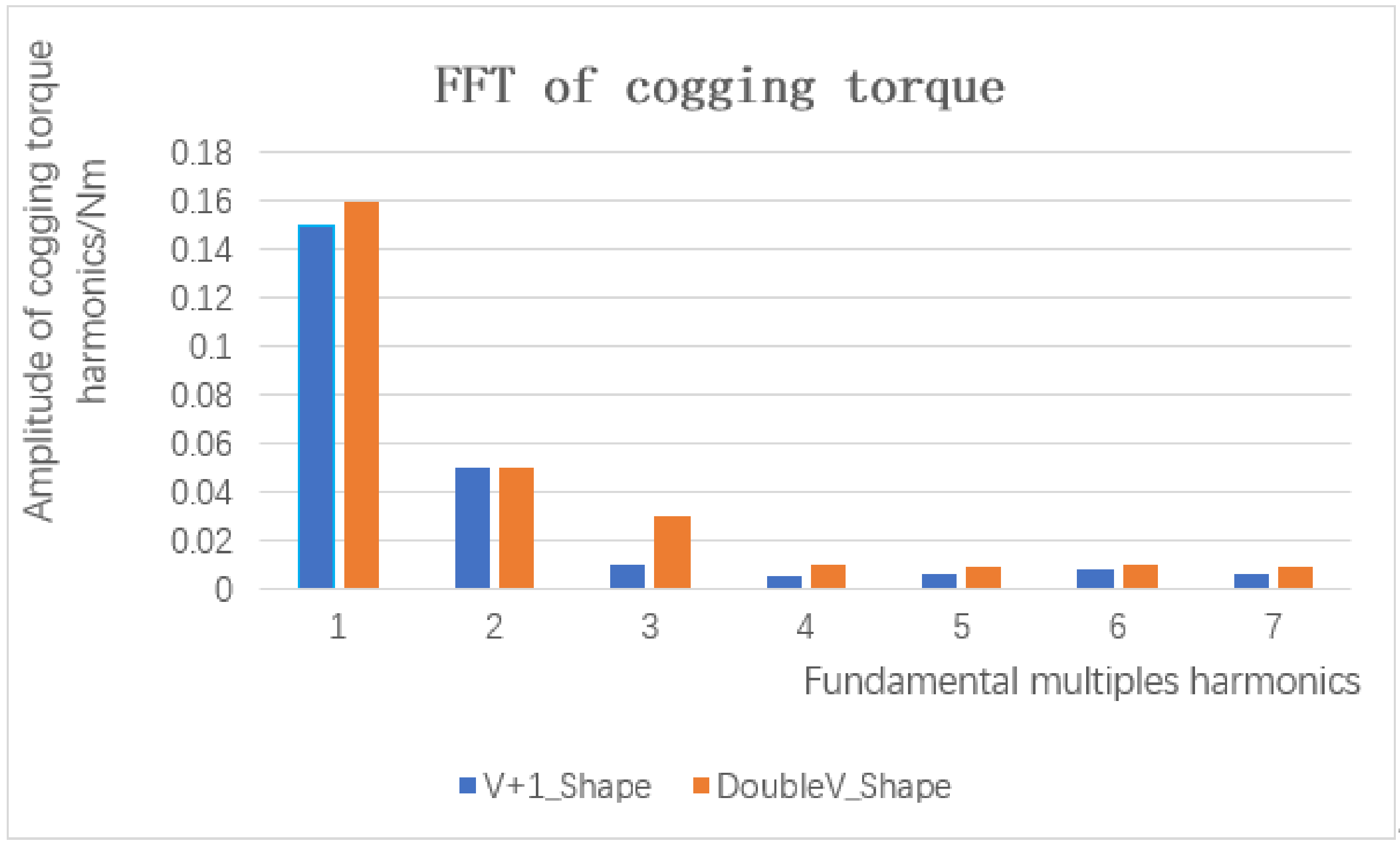
Cogging torque is an important no-load electromagnetic characteristic. The torque ripple in a vehicle’s permanent magnet synchronous motor is largely related to the cogging torque. From Figure 5, it is revealed that the cogging torque of the V+1-shaped rotor and the double-V-shaped rotor is noticeably smaller than that of the V-shaped rotor. Figure 6 provides a further comparison of the V+1-shaped and double-V-shaped rotors. From Figure 6, we can infer that the harmonics of the V+1-shaped rotor are better than those of the double-V-shaped rotor.

Figure 5.
Cogging torque of different rotor shapes.

Figure 6.
FFT of cogging torque.
4.2. Analysis of Peak Load Electromagnetic Performance
The peak torque of the motor is 180Nm@350Arms. By comparing the torque, torque ripple, current angle, stator tooth flux density, and stator yoke flux density under the peak torque of three rotor structures, the maximum torque that can be the output of three rotor structures was determined. Figure 7 shows the torque summary diagram of three rotor structures. We can discern that the V+1-shaped rotor structure has the largest torque, and the V-shaped rotor structure has the smallest torque. Table 5 shows the summary of different performance parameters.
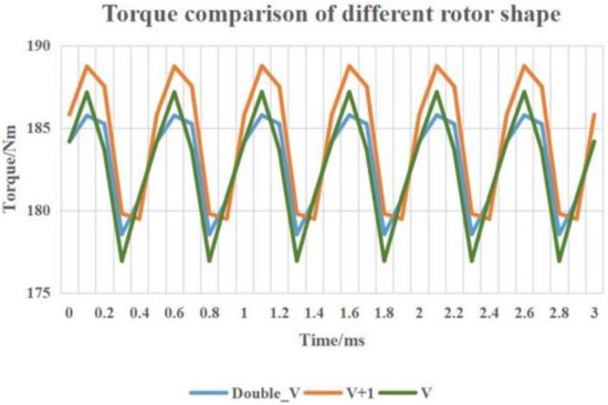
Figure 7.
Torque of different rotor shapes.
Table 5.
Summary of different performance parameters.
In Table 6, B_Tooth is magnetic induction intensity in the teeth, and B_yoke is magnetic induction intensity in the yoke.
Table 6.
Summary of different performance parameters.
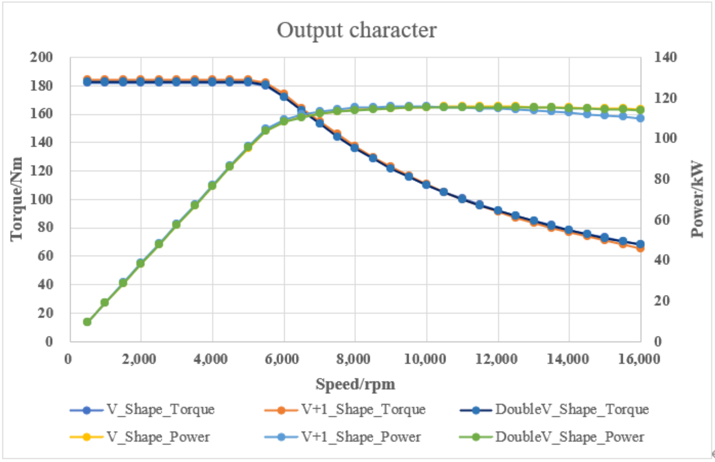
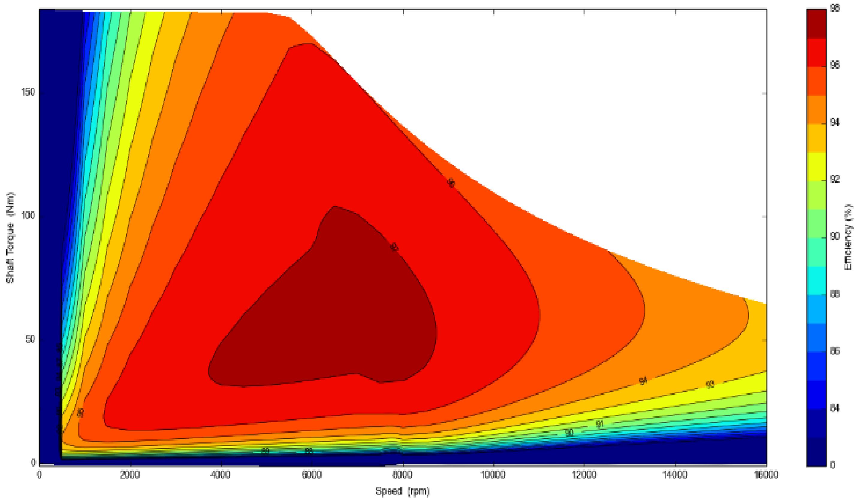
We consider a machine design to be good if the machine has a large torque, small torque ripple, small B_Tooth, small B_yoke, and small reluctance torque. Among those performance indicators, the motor’s torque and ripple are the most important. Based on the analysis of the maximum torque conditions of the three rotor structures, the V+1-shaped rotor structure has the largest torque and the lowest proportion of reluctance torque, the double-V-shaped rotor structure has the lowest torque ripple but the highest proportion of reluctance torque, and the V-shaped rotor has the worst performance, compared with the other two. At the same time, in this study, maximum output characteristic data were calculated and efficiency maps of the three kinds of rotor structures were drawn. Figure 8 shows the comparison chart of external characteristic output curves of the three kinds of rotor structures under the same boundary conditions. Figure 9, Figure 10 and Figure 11 show the corresponding efficiency maps of the three kinds of rotor structures. Table 6 shows the comparison data of output characteristics of the three kinds of rotor structures.
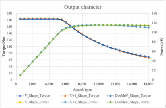
Figure 8.
Output characteristics of the three different rotor shapes.
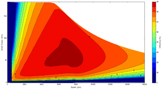
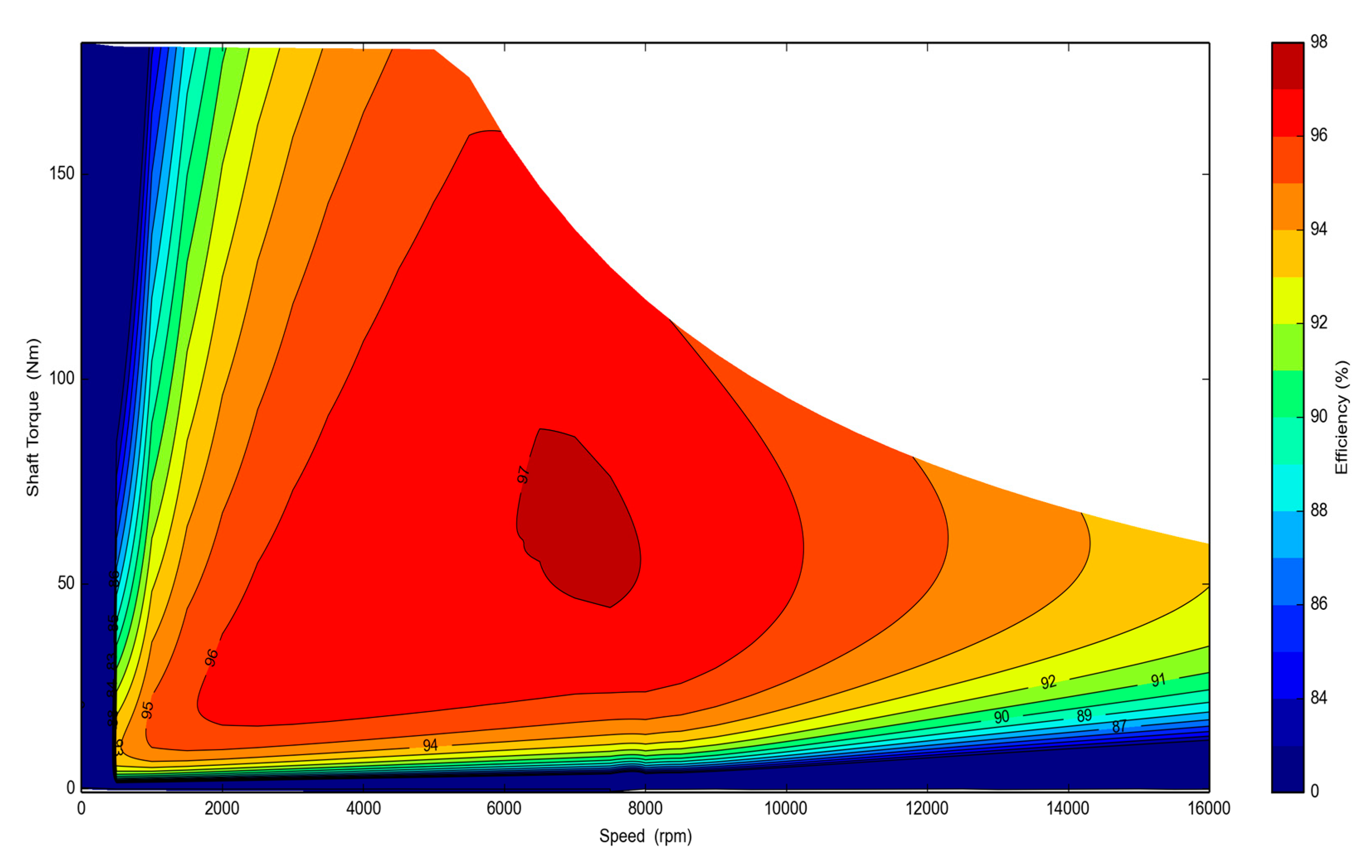
Figure 9.
Efficiency map of double-V-shaped rotor.

Figure 10.
Efficiency map of V+1-shaped rotor.

Figure 11.
Efficiency map of V-shaped rotor.
By comparing the three types of rotor structures in terms of both torque and power performance, it is revealed that the V+1-shaped rotor structure is the largest but has the least power, at 16,000 rpm. However, according to the current development trend of new energy drive motors, the time during which the machines are operated at the highest working speeds and they have to generate large torque values is rather short. Considering the maximum output characteristic data of the three rotor structures, the performances of the three rotor structures exhibit no significant differences. However, in terms of permanent magnet volume installed in the three rotors, the V+1-shaped rotor structure has a considerable advantage.
Table 7 shows the comparison data of efficiency maps of the three kinds of rotor structures.
Table 7.
Summary of different performance parameters.
A comparison of the three rotor structures reveals that the V+1-shaped rotor structure has the highest efficiency, and the efficiency area with efficiency greater than 97% is the largest. The efficiency greater than 85% and 90% are in the middle of the three rotor structures, but there is little difference with the double-V-shaped structure. Based on the operation conditions of new energy drive motors, the V+1-shaped rotor structure is the best-performing one.
4.3. Analysis of NVH Performance
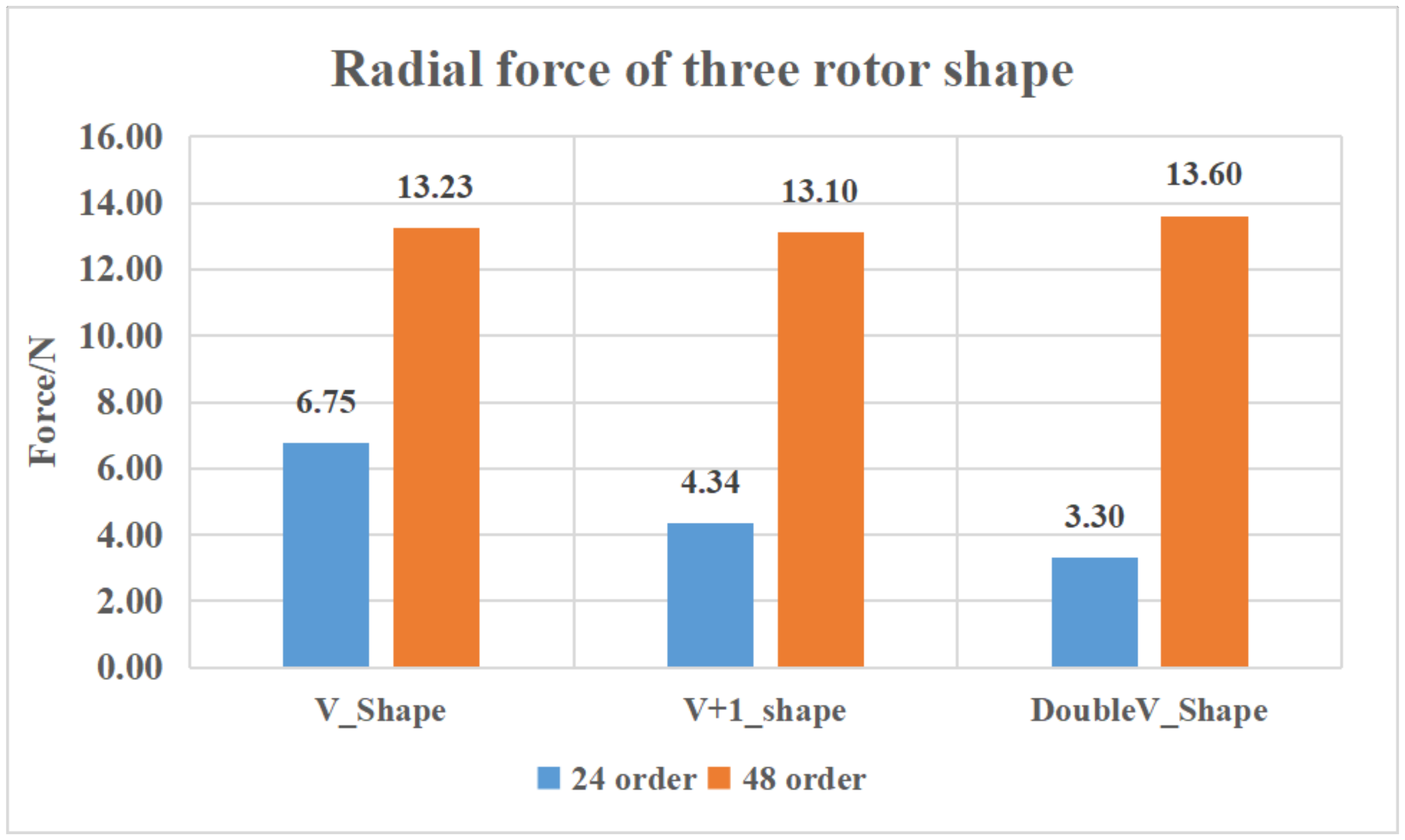
From the above results, it is evident that, among the three types of rotor structures, the V+1-shaped rotor structure has the best overall performance, and the radial electromagnetic force is the most direct characterization of motor vibration and noise. Since the three motors use the same stator structure, by comparing the radial electromagnetic force, it can be determined which structure is the best for vibration and noise. Figure 12 shows a comparison diagram of the 24th, 48th, and 96th harmonics of the three rotor structures under the zero-order force wave. Among the three types of rotor structures, the V-shaped rotor structure is the largest at 24 h, and the double-V-shaped rotor is the largest at 48th.
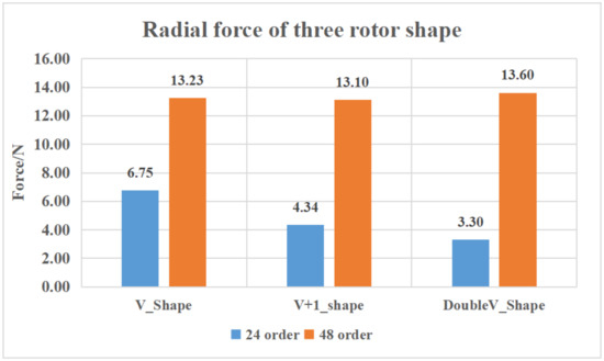
Figure 12.
Order comparison of the three rotors.
5. Experimental Verification
Two experimental prototypes of V-shaped rotor and V+1-shaped rotor were tested. The test bench is shown in Figure 13. Based on theoretical analysis and finite element simulation results, it can be seen that the structural performance of the V+1-shaped rotor is the best, and that of the V-shaped rotor is the worst. Two motors were made and verified by experiments with the same subassembly.
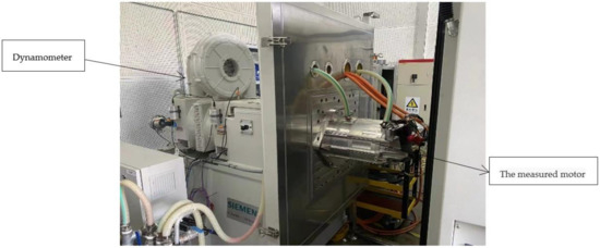
Figure 13.
Test bench of motors.
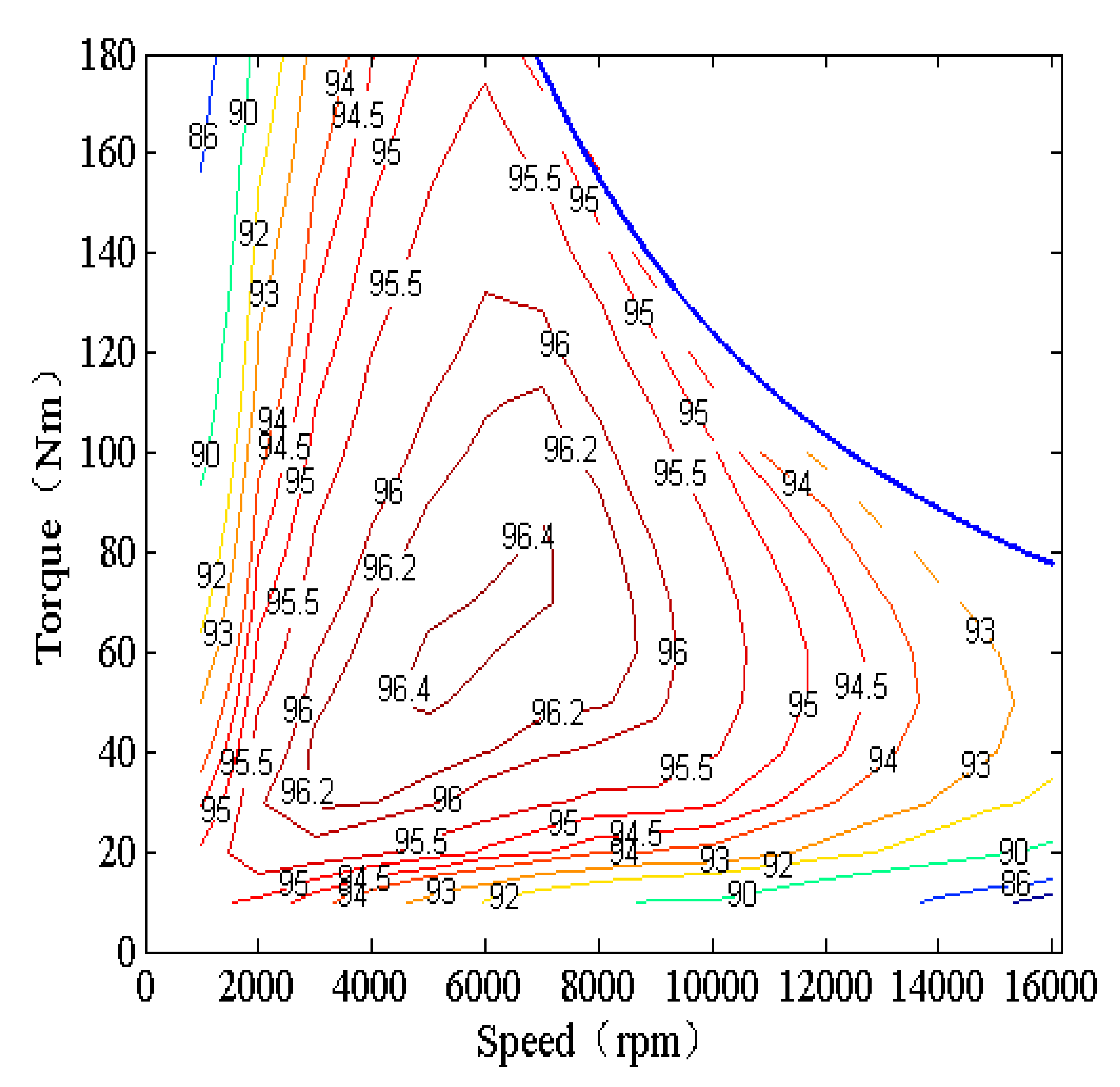
The measured efficiency values of the two motors are shown in Figure 14 and Figure 15. The motor with the V+1-shaped rotor has better efficiency performance.
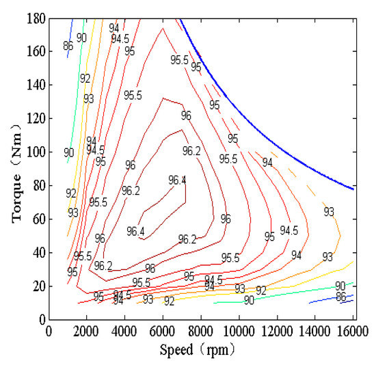
Figure 14.
Efficiency map of V-shaped rotor.
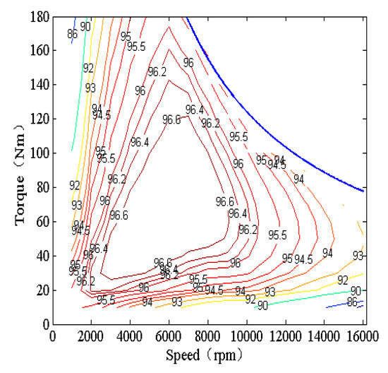
Figure 15.
Efficiency map of V+1-shaped rotor.
From Figure 14 and Figure 15, we can infer that the largest efficiency of the V-shaped rotor is 96.4%, with a small area, and the largest efficiency of the V+1 shaped rotor is 96.6%, with a large area. Therefore, the V+1-shaped rotor has better efficiency.
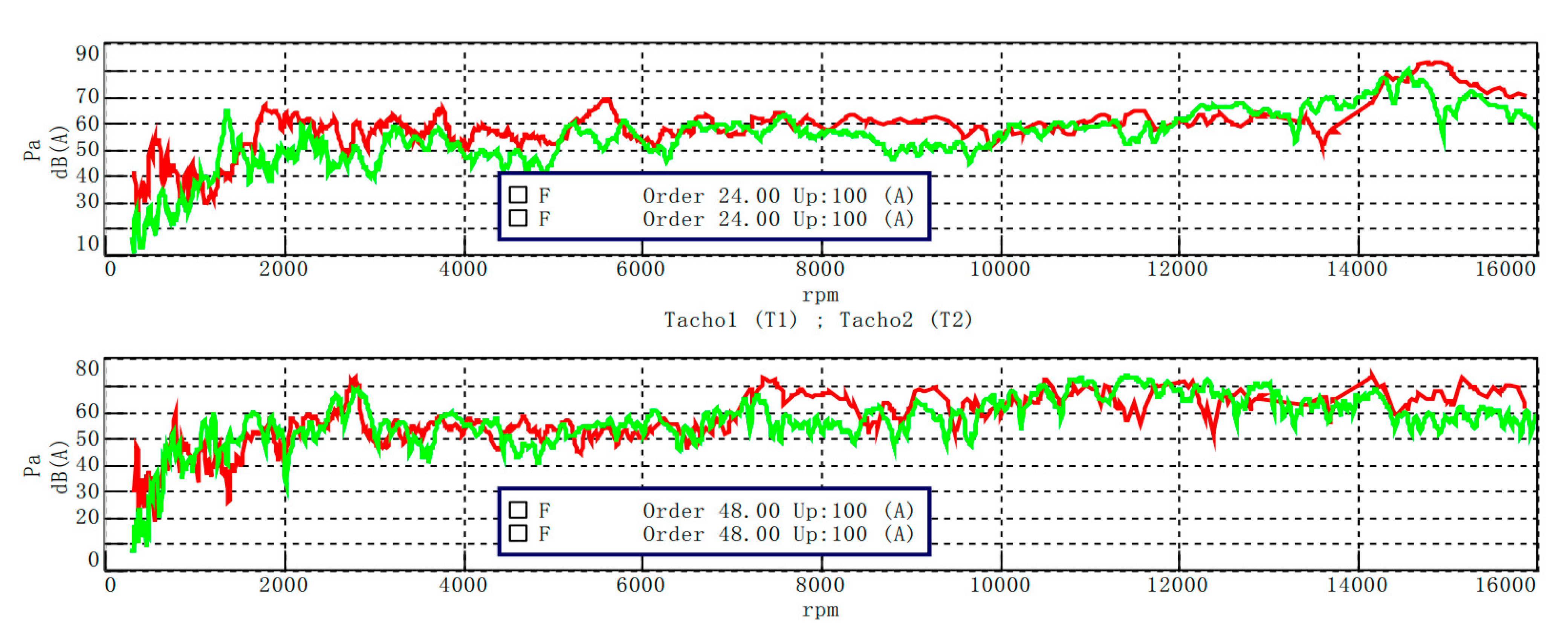
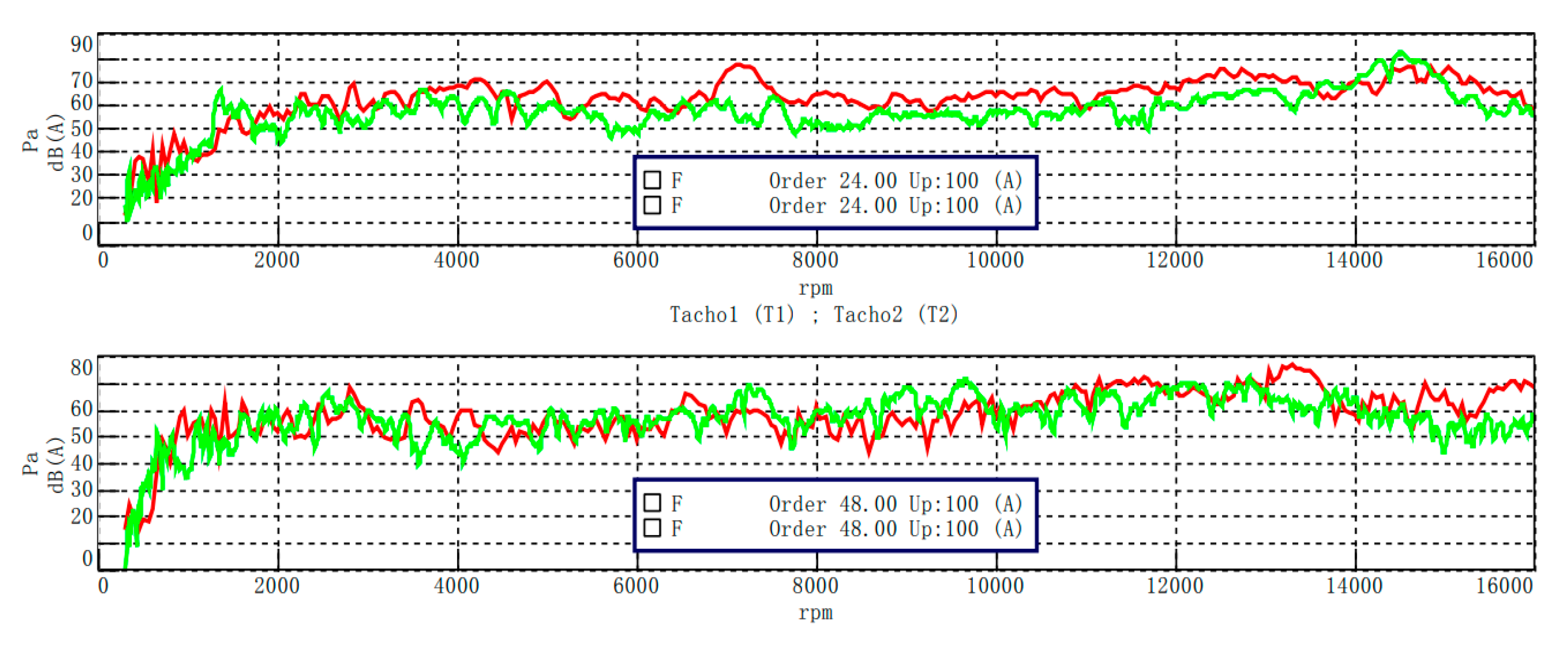
Noise vibration harshness verification is shown in Figure 16, which shows the motor noise tested at 50% maximum acceleration. Red is V-shaped rotor data, and green is V+1-shaped rotor data. Figure 17 illustrates the 50% energy recovery NVH data.
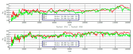
Figure 16.
Motor noise tested at 50% maximum acceleration.
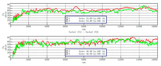
Figure 17.
Motor noise tested at 50% energy recovery.
For the automotive electric drive system, when the speed ratio of the drive system is 10–12, the frequency segment of the automotive permanent magnet synchronous motor is mainly 6000–10,000 Hz [17]. As is shown above, in terms of noise vibration harshness, the 24th order of V-shaped rotor is inferior to that of V+1-shaped rotor, the 48th order of V-shaped rotor is inferior to that of V+1-shaped rotor at 50% maximum acceleration test, and the 48th order of V+1-shaped rotor is inferior to that of V-shaped rotor at 50% energy recovery test. Similarly, through the measured data of efficiency, it can be seen that the V+1 rotor still has advantages.
6. Conclusions
Based on the same index, three kinds of rotors were designed, the corresponding finite element analysis was carried out, and the performance differences of the three kinds of rotors under the same boundary conditions were provided. Two kinds of rotors were selected to make prototypes for testing, and the following conclusions are obtained:
By comparing the efficiency data, it was revealed that the efficiency of the V+1-shaped rotor structure is better than that of the V-shaped rotor structure.
Since the motor temperature was controlled between 65 and 85 °C, during the motor efficiency test, and 120 °C during simulation, there was a certain difference. The simulation will be optimized and corrected in future research.
Through theoretical analysis, it was shown that the NVH performance of the V+1-shaped rotor structure is better than that of the V-shaped rotor structure. The measured results verified the correctness of the finite element analysis.
Author Contributions
Conceptualization, K.Z. and J.L.; methodology, K.Z. and J.L.; software, K.Z.; validation, K.Z. and J.L; formal analysis, K.Z.; investigation, K.Z.; resources, J.L.; data curation, K.Z.; writing—original draft preparation, K.Z.; writing—review and editing, K.Z. and J.L; visualization, K.Z.; supervision, J.L.; project administration, J.L.; funding acquisition, J.L. All authors have read and agreed to the published version of the manuscript.
Funding
This research received no external funding.
Institutional Review Board Statement
Not applicable.
Informed Consent Statement
Not applicable.
Data Availability Statement
All the data are shown in the tables and figures of this paper.
Conflicts of Interest
The authors declare no conflict of interest.
References
- Ma, C.G.; Li, J.M.; Zhao, H.C.; Wang, J.H.; Yin, X.R.; Zuo, S.G.; Wu, X.D.; Lu, H.F. 3-d analytical model of armature reaction field of ipmsm with multi-segmented skewed poles and multi-layered flat wire winding considering current harmonics. IEEE Access 2020, 8, 151116–151124. [Google Scholar] [CrossRef]
- Liang, Y.P.; Zhao, F.C.; Xu, K.W.; Wang, W.H.; Liu, J.; Yang, P.P. Analysis of copper loss of permanent magnet synchronous motor with formed transposition winding. IEEE Access 2021, 9, 101105–101114. [Google Scholar] [CrossRef]
- Xu, M.M.; Liu, G.H.; Chen, Q.; Zhao, W.X. Fast calculation method of optimal flux-barrier-end position for torque ripple minimisation in SynRMs with and without PMs. IET Electr. Power Appl. 2020, 14, 705–715. [Google Scholar] [CrossRef]
- Arafat, A.K.M.; Choi, S. Active current harmonic suppression for torque ripple minimization at open-phase faults in a five-phase PMa-SynRM. IEEE Trans. Ind. Electron. 2019, 66, 922–931. [Google Scholar] [CrossRef]
- Lu, Y.; Li, J.; Qu, R.H.; Ye, D.L.; Lu, H.X.; Sun, J.B.; Ge, M.; Xu, H.W. Electromagnetic force and vibration analysis of permanent-magnet-assisted synchronous reluctance machines. IEEE Trans. Ind. Appl. 2018, 54, 4246–4256. [Google Scholar] [CrossRef]
- Geng, S.T.; Zhang, Y.; Qiu, H.B.; Yang, C.X.; Yi, R. Influence of harmonic voltage coupling on torque ripple of permanent magnet synchronous motor. Arch. Electr. 2019, 68, 399–410. [Google Scholar] [CrossRef]
- Ou, L.Z.; Wang, X.F.; Xiong, F.; Ye, C.Y. Reduction of torque ripple in a wound-rotor brushless doubly-fed machine by using the tooth notching. IET Electr. Power Appl. 2018, 12, 635–642. [Google Scholar] [CrossRef]
- Liu, X.D.; Hao, C.; Zhao, J.; Belahcen, A. Research on the performances and parameters of interior PMSM used for electric vehicles. IEEE Trans. Ind. Electron. 2016, 63, 3533–3545. [Google Scholar] [CrossRef]
- Long, S.A.; Zhu, Z.Q.; David, H. Vibration behaviour of stators of switched reluctance motors. IEE Proc. Electr. Power Appl. 2001, 148, 257–264. [Google Scholar] [CrossRef]
- Levent, A.H.; Lordoglu, A.; Aydeniz, M.G. Design and Optimization of Permanent Magnet Synchronous Motor for Electric Vehicle Applications. In Proceedings of the 2020 2nd Global Power, Energy and Communication Conference (GPECOM), Izmir, Turkey, 20–23 October 2020; pp. 148–151. [Google Scholar] [CrossRef]
- Ma, C.G.; An, Y.S.; Zhao, H.C.; Guo, S.L.; Yin, X.R.; Lu, H.F. 3-D Analytical Model and Direct Measurement Method of Ultra-Thin Open-Circuit Air-Gap Field of Interior Permanent Magnet Synchronous Motor With Multi-Segmented Skew Poles and Multi-Layered Flat Wire Windings for Electric Vehicle. IEEE Trans. Energy Convers. 2020, 35, 1316–1326. [Google Scholar] [CrossRef]
- Tong, W.M.; Dai, S.H.; Wu, S.N.; Tang, R.Y. Performance comparison between an amorphous metal PMSM and a silicon steel PMSM. IEEE Trans. Magn. 2019, 55, 1–5. [Google Scholar] [CrossRef]
- Jin, H.L.; Kim, D.W.; Song, J.Y.; Jung, S.Y.; Kim, Y.J. Design of 100 kW propulsion motor for electric conversion vehicle based on vehicle driving performance simulation. In Proceedings of the 2016 IEEE Transportation Electrification Conference and Expo, Asia-Pacific (ITEC Asia-Pacific), Busan, Korea, 1–4 June 2016; pp. 412–416. [Google Scholar] [CrossRef]
- Verdyck, D.; Belmans, R. An acoustic model for a permanent magnet machine: Modal shapes and magnetic forces. IEEE Trans. Ind. Appl. 1994, 30, 1625–1631. [Google Scholar] [CrossRef]
- Xing, Z.Z.; Wang, X.H.; Zhao, W.L. Research on weakening measure of radial electromagnetic force waves in permanent magnet synchronous motors by inserting auxiliary slots. IET Electr. Power Appl. 2020, 14, 1381–1395. [Google Scholar] [CrossRef]
- Li, X.H.; Liu, C.J.; Mei, B.S.; Wei, S.R.; Xia, N.H. Vibration and Noise Sources Analysis of IPMSM for Electric Vehicles in a Wide-speed Range. Proc. CSEE 2018, 38, 5219–5227. (In Chinese) [Google Scholar] [CrossRef]
- Girgis, R.S.; Verma, S.P. Resonant frequencies and vibration behavior of stators of electrical machines as affected by teeth, windings, frame and laminations. IEEE Trans. Power Appar. Syst. 1979, 98, 1446–1455. [Google Scholar] [CrossRef]


Publisher’s Note: MDPI stays neutral with regard to jurisdictional claims in published maps and institutional affiliations. |
© 2022 by the authors. Licensee MDPI, Basel, Switzerland. This article is an open access article distributed under the terms and conditions of the Creative Commons Attribution (CC BY) license (https://creativecommons.org/licenses/by/4.0/).