
Comprehensive Comparison of Two Fault Tolerant Axial Field Modular Flux-Switching Permanent Magnet Machines with Different Stator and Rotor Pole-Pairs Combinations


Abstract
:1. Introduction
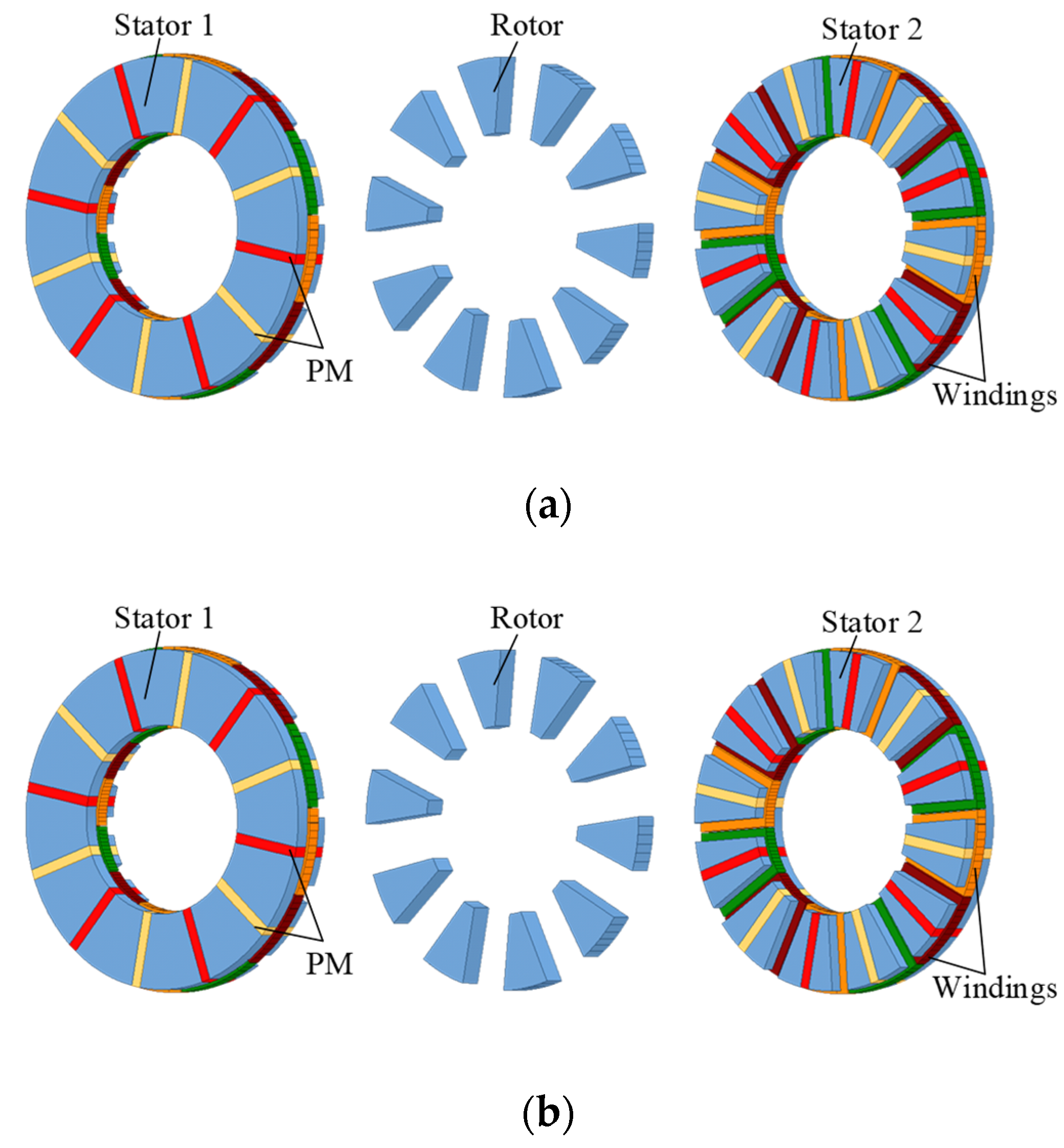
2. Topologies of AFFSPM Machines
3. Stator Slots and Rotor Pole-Pairs Combination Principles
4. Static Performance Evaluation
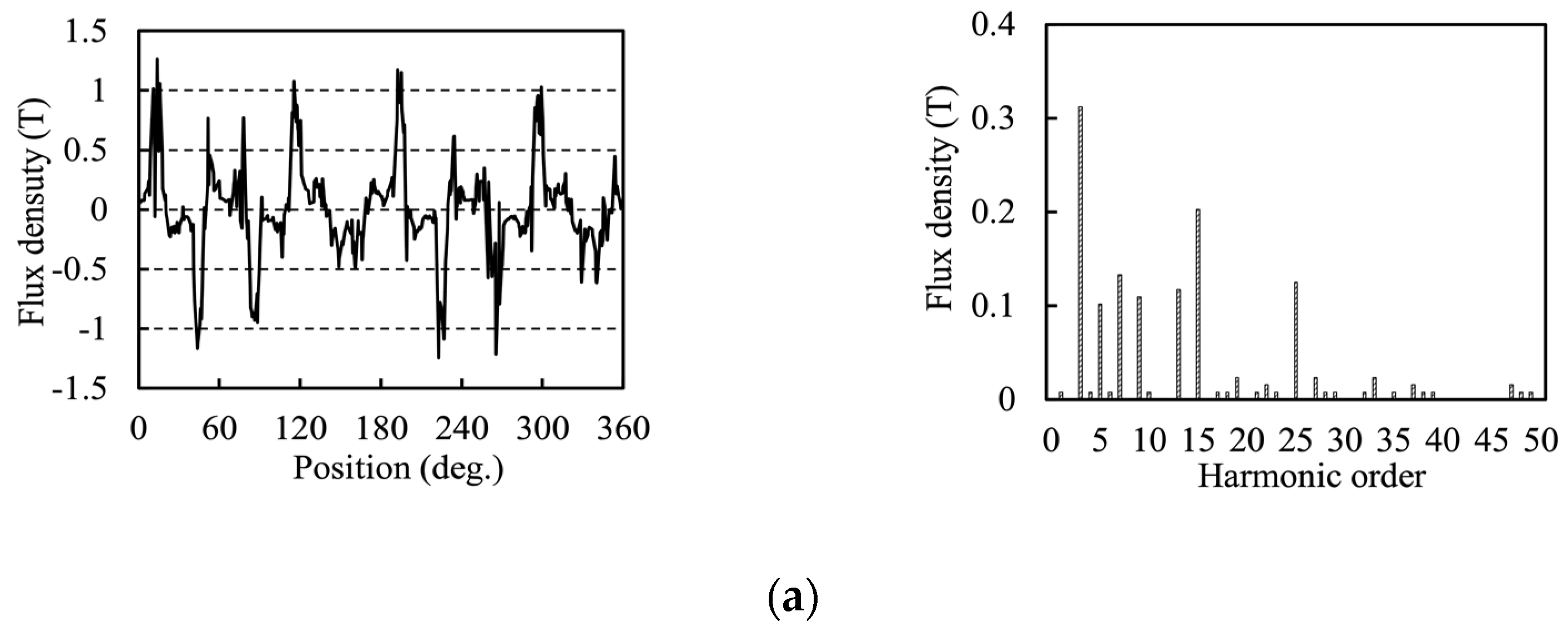
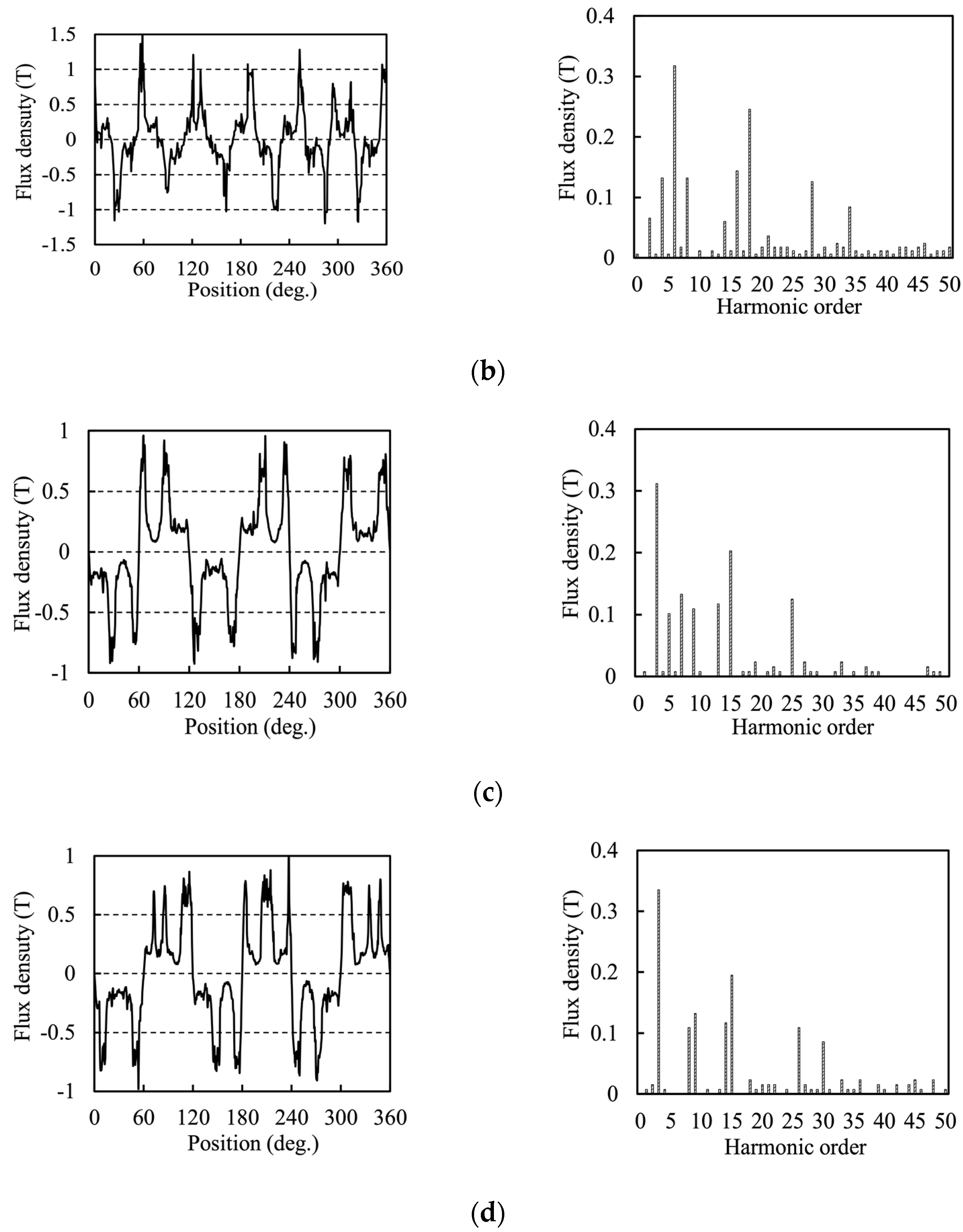
4.1. Air-Gap Flux Density
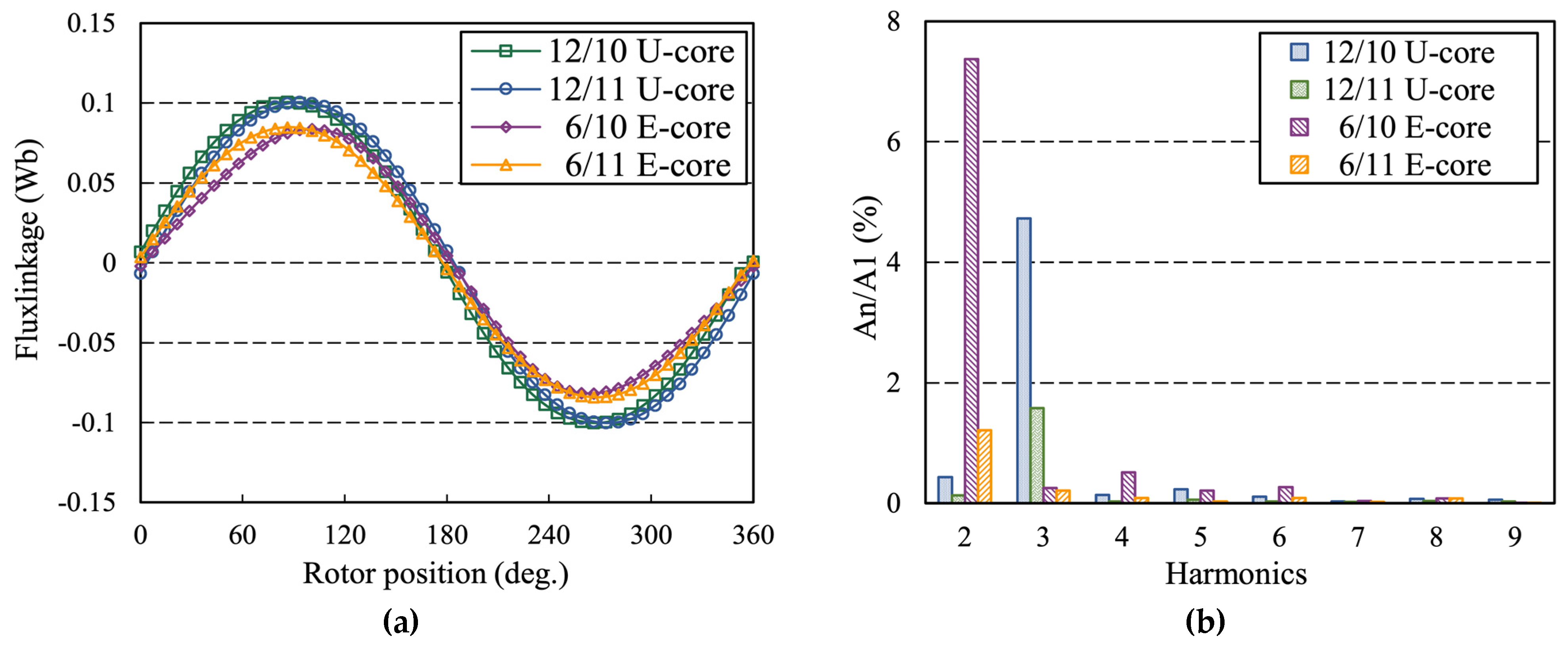
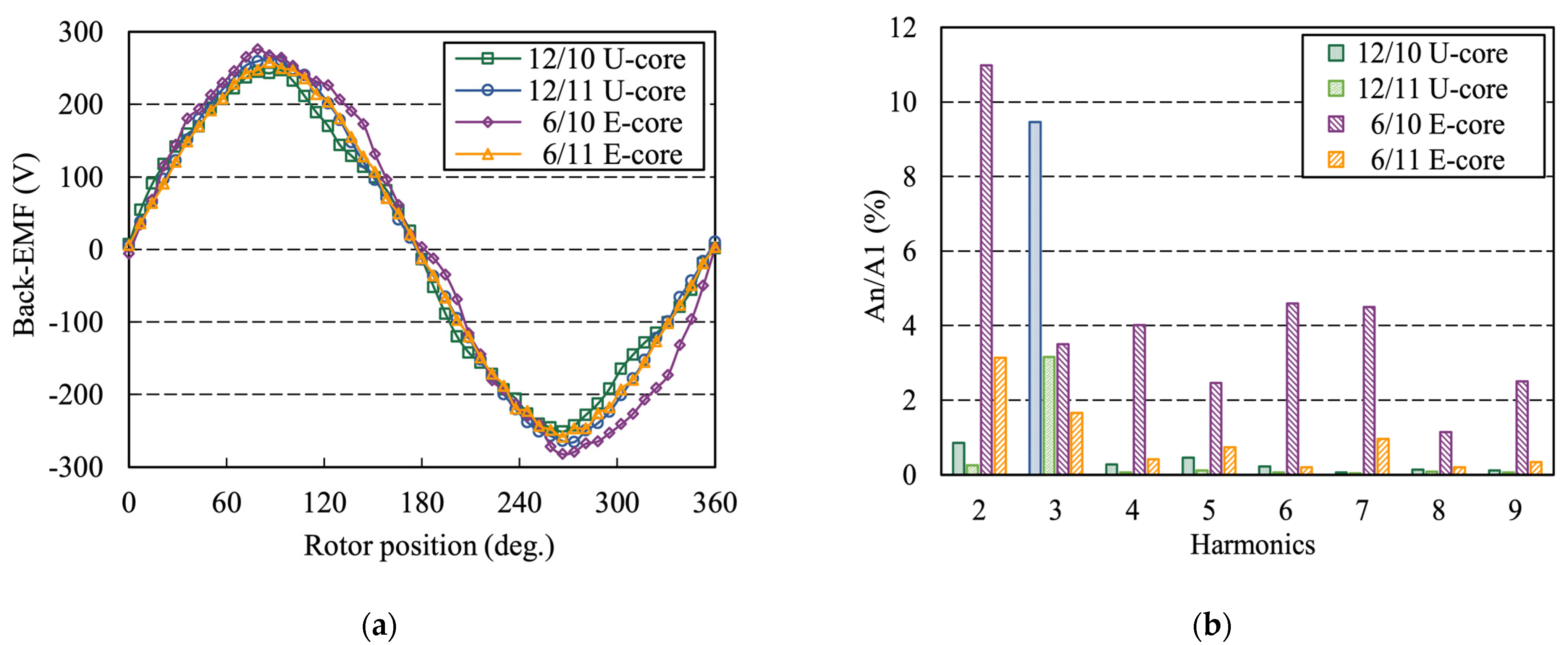
4.2. PM Flux Linkage and Back-EMF
4.3. Inductance
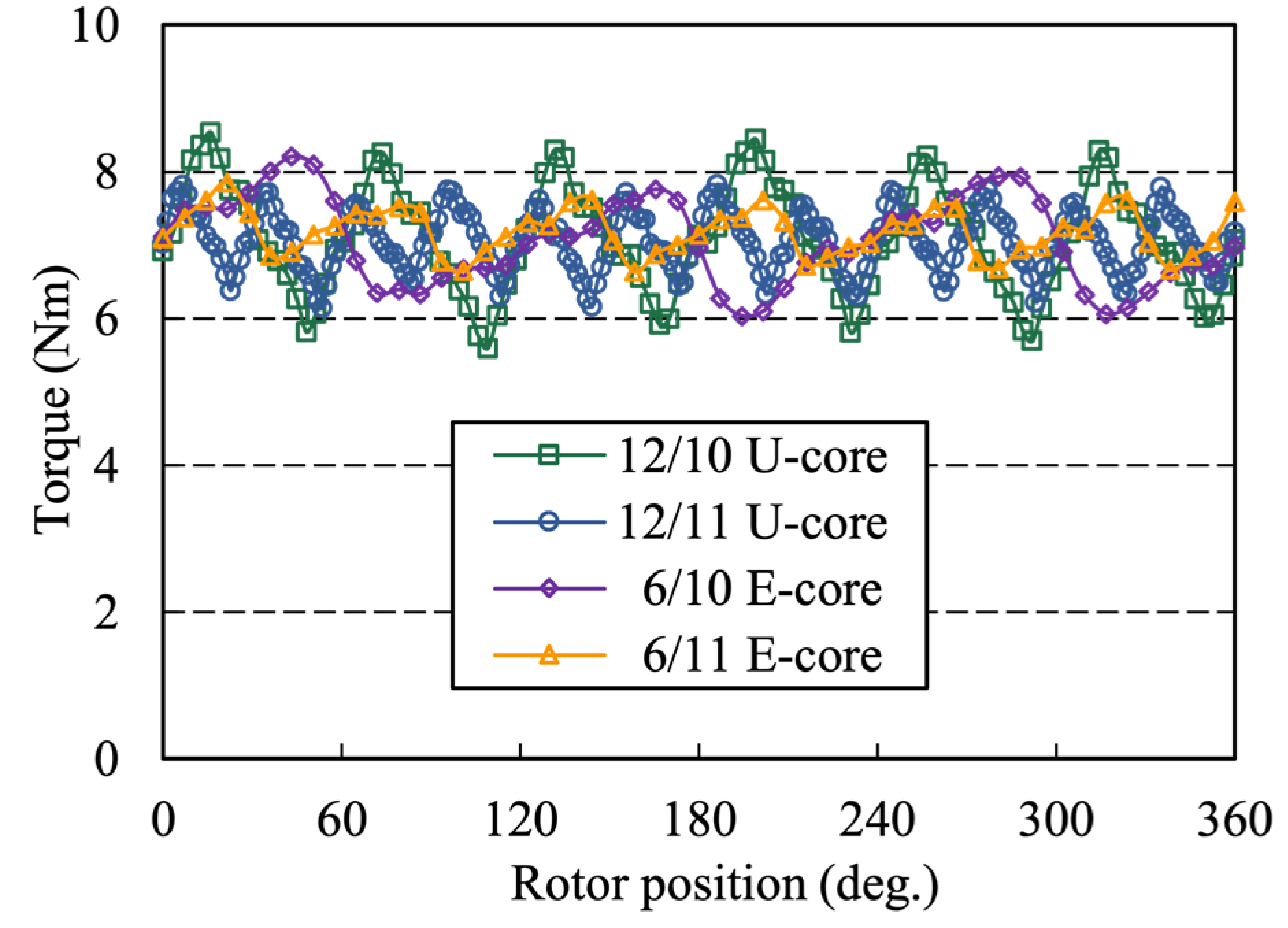
4.4. Electromagnetic Torque
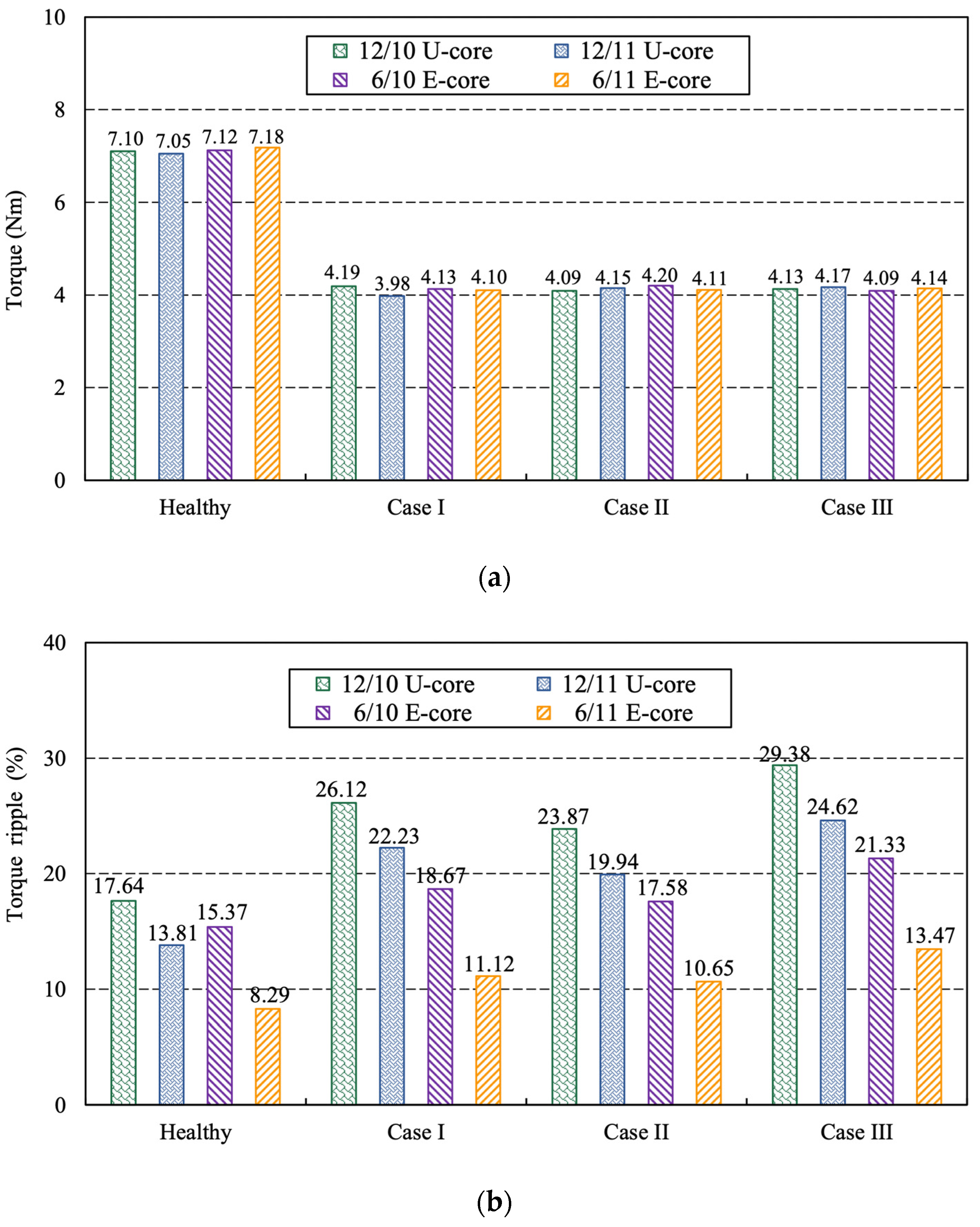
5. Fault-Tolerant Operation Performance Comparison
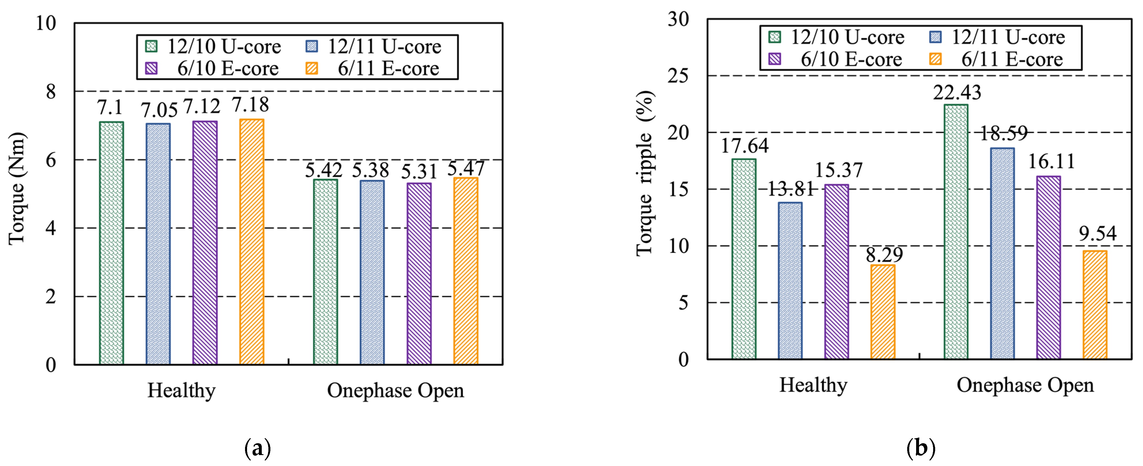
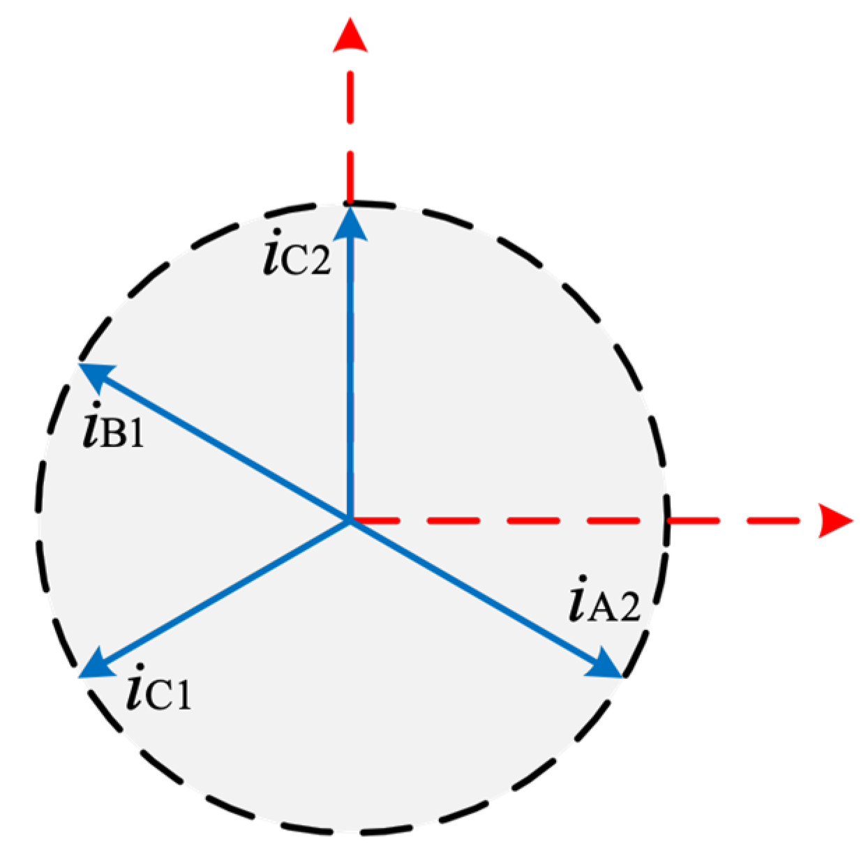
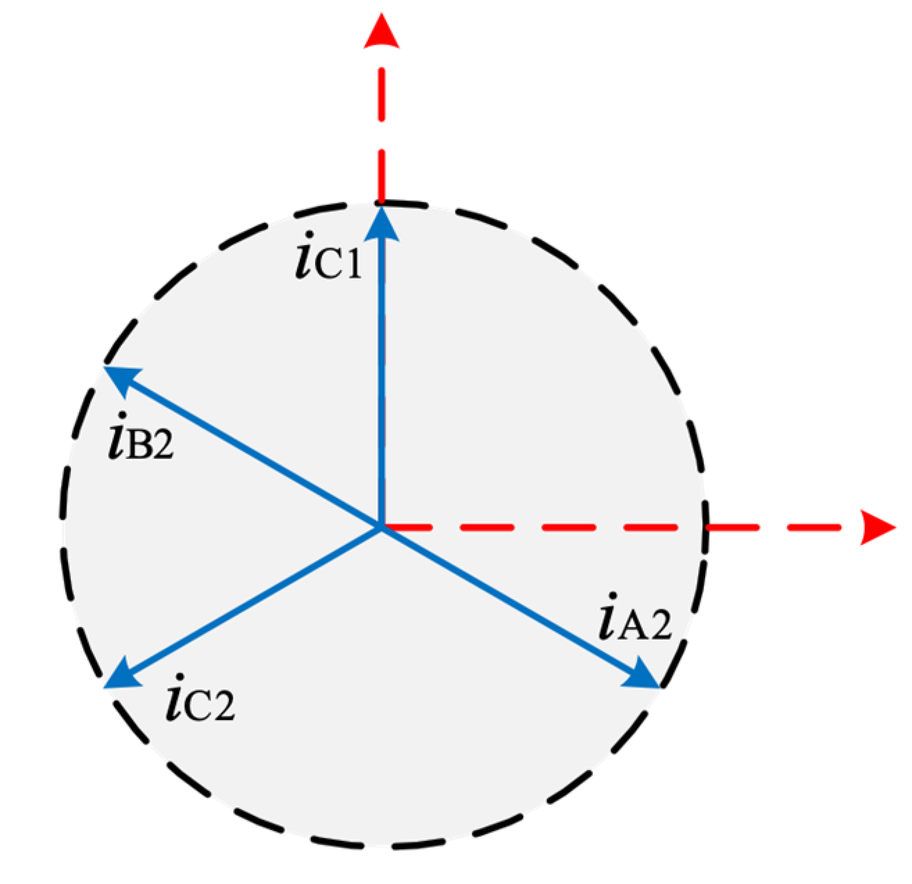
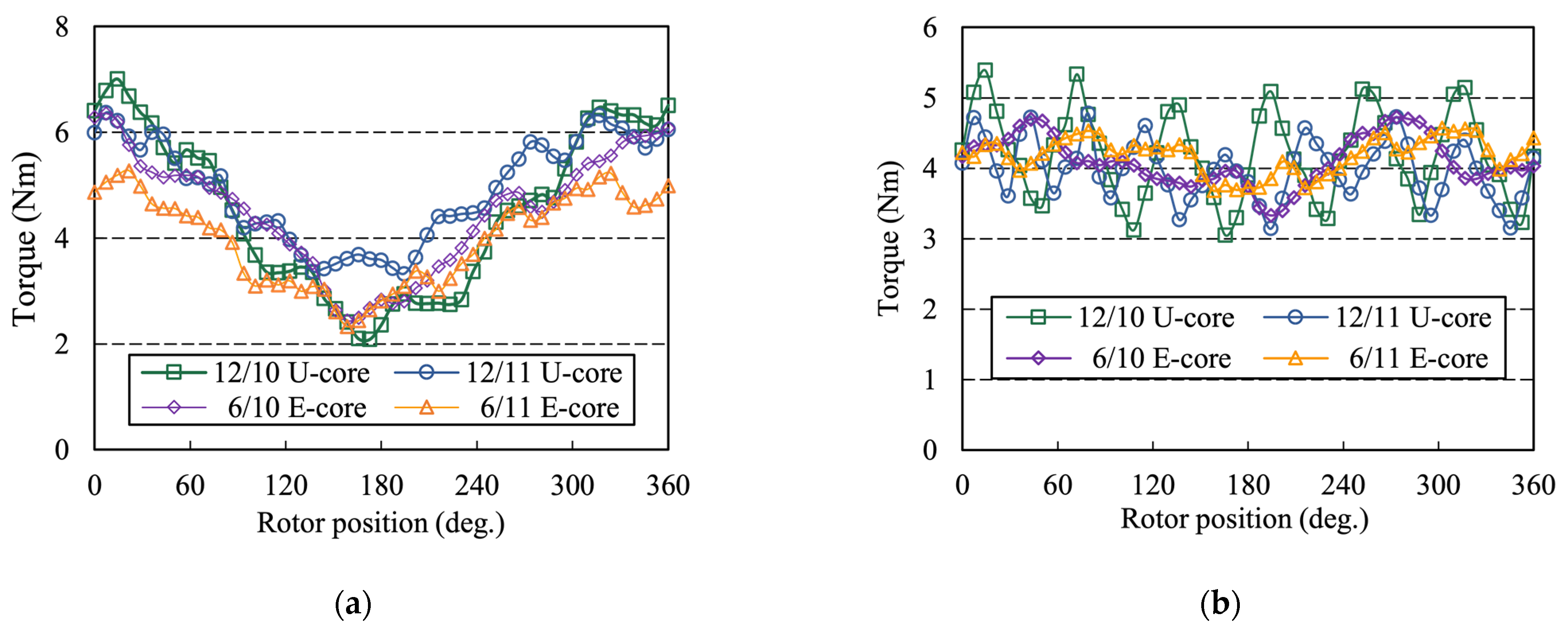
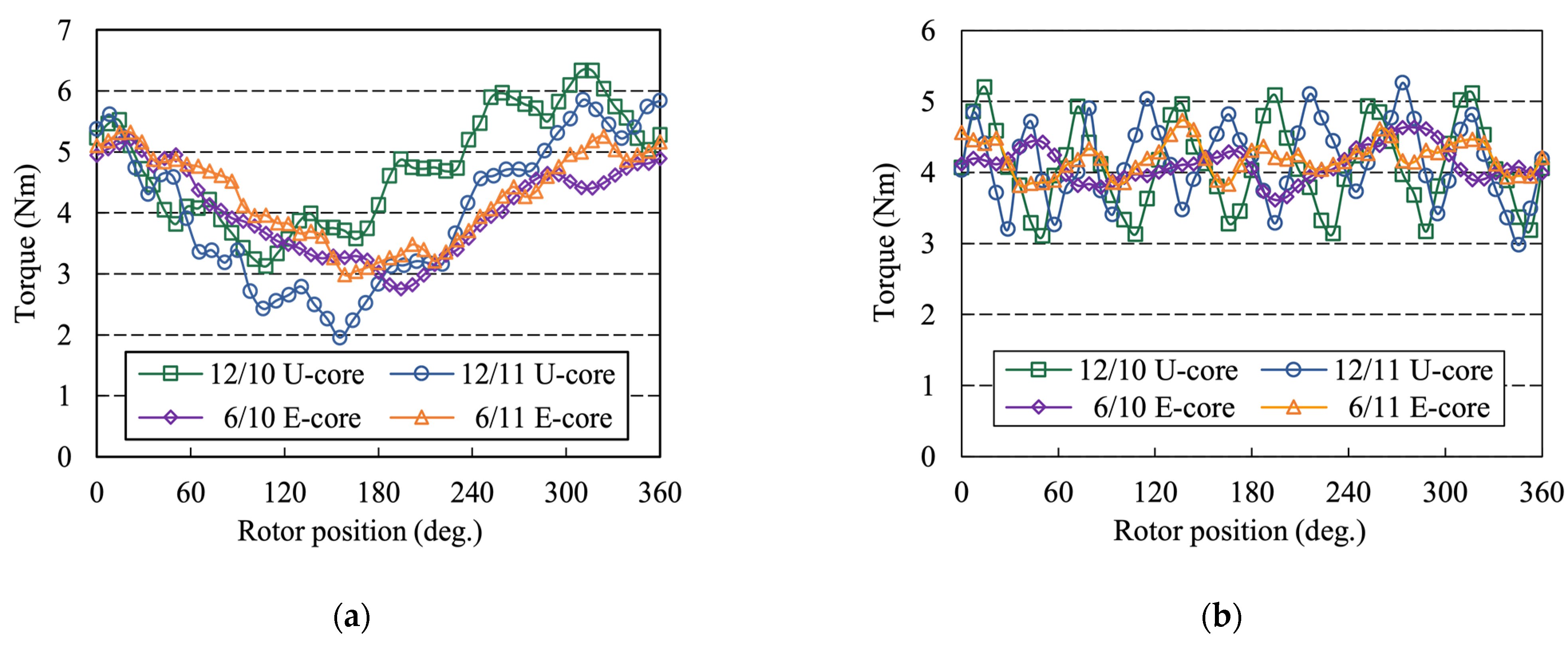
5.1. One-Phase Open
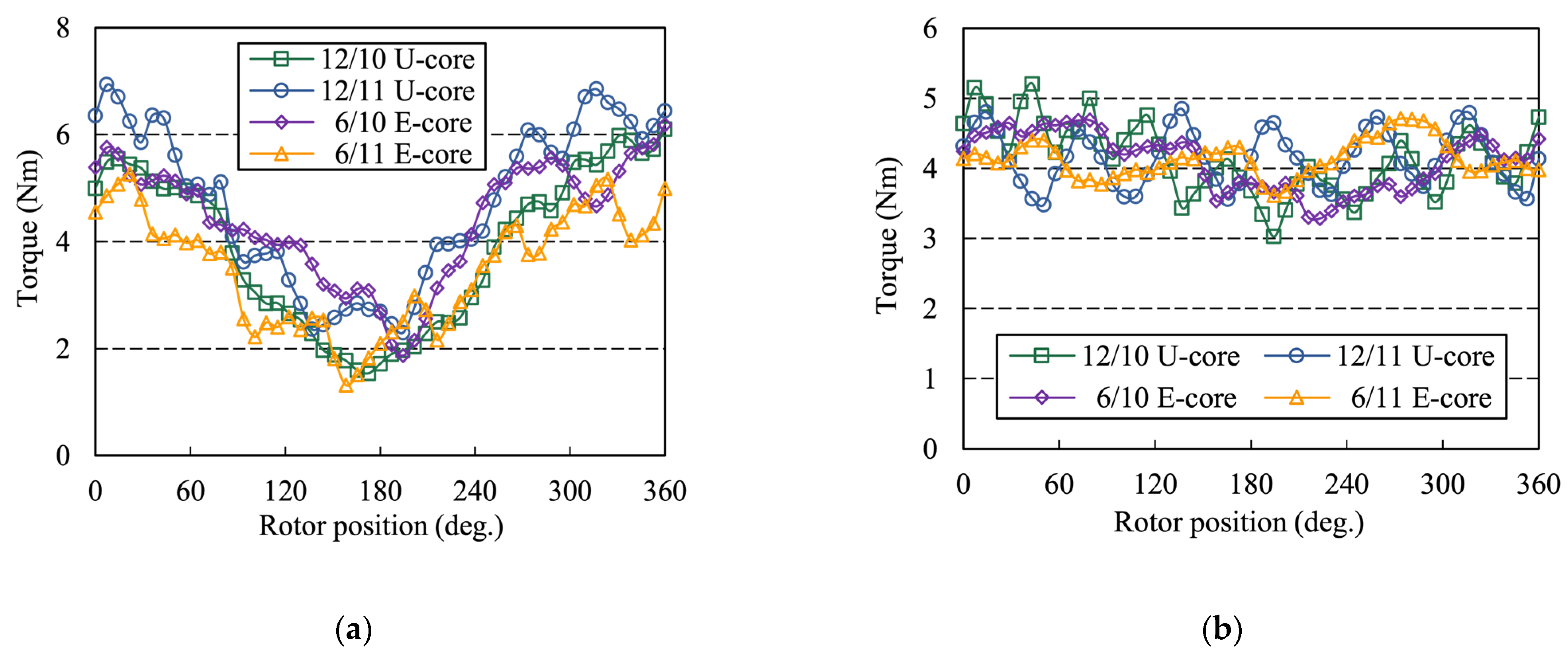
5.2. Two-Phase Open
6. Conclusions
- (1)
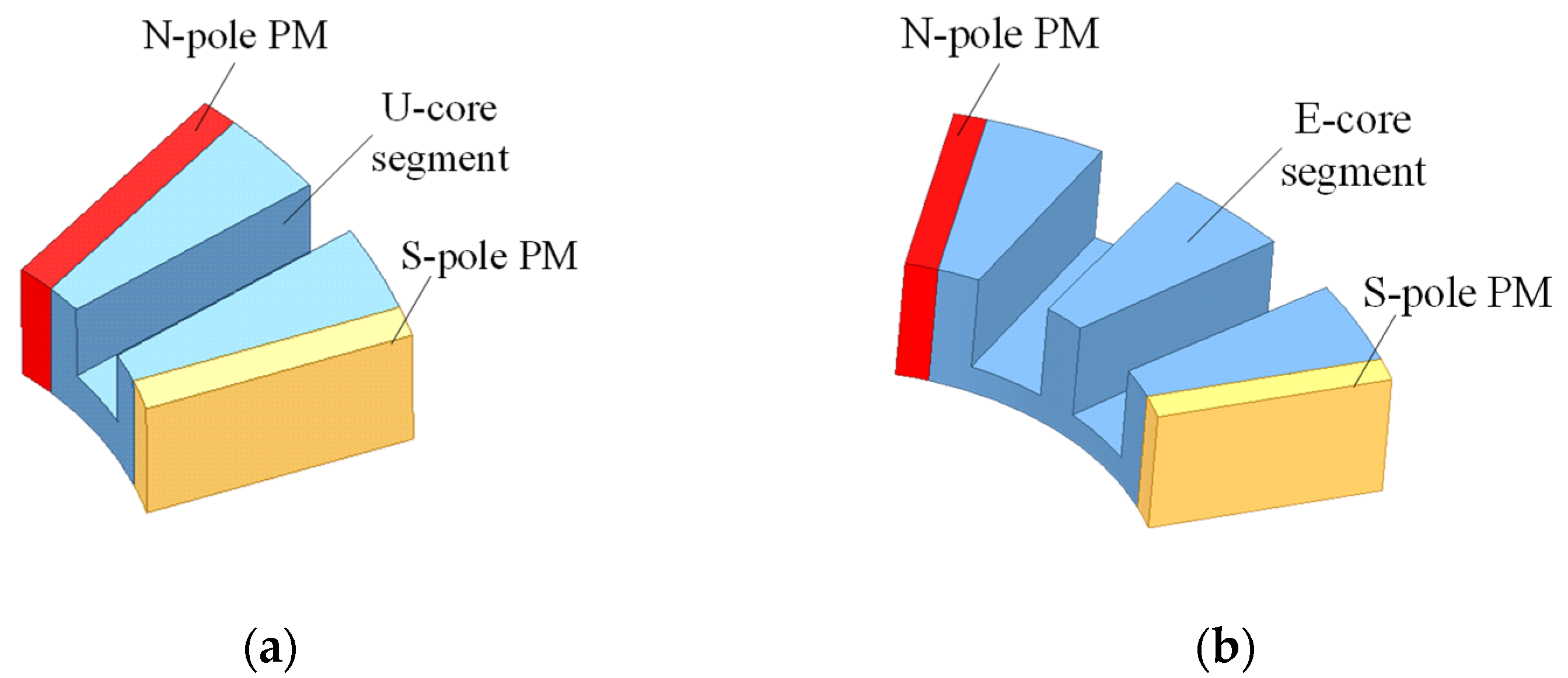
- The E- and U-core AFFSPM machines apply different feasible stator-slot/ rotor-pole-pairs combinations, which can be obtained by the slot-conducotor back-EMF star vectors theory.
- (2)
- The total harmonic distortion (THD) value of PM flux linkage and back-EMF of 10 rotor pole-pairs machines is higher than that of the 11-rotor pole-pairs machines because of the winding complementarity. Furthermore, the effective harmonics of open-circuit air-gap flux of four candidates can be classified into the dominant harmonic and modulated harmonics, which is in agreement with the field modulation theory.
- (3)
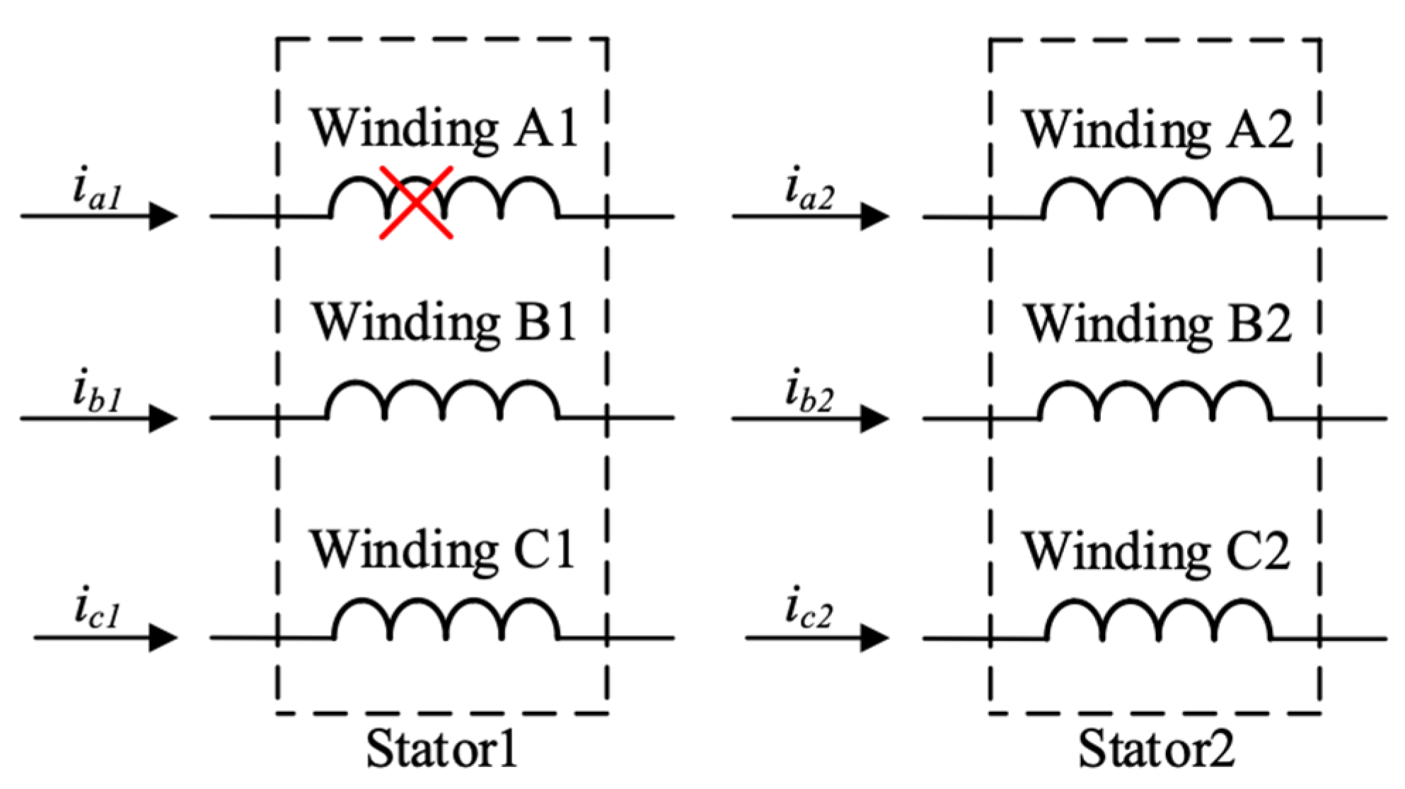
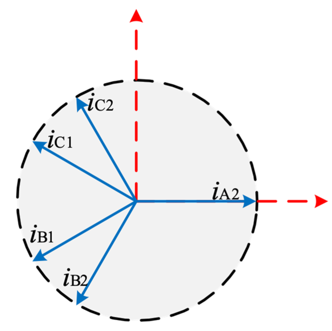
- Both U- and E-core machines consist of two stators and one rotor. The two sets windings on each stator provide a natural convenience for double three phases configurations, which can enhance the fault-tolerant capability.
- (4)
- The middle stator teeth of E-core stator segments lead to an enhancement of the magnetic isolation and the single layer windings, which significantly improves the fault-tolerant operation ability under one- and two-phase open-circuited conditions.
- (5)
- The E-core stator segments reduce the number of PMs and increase the distance between adjacent PMs, which not only leads to a smaller cogging torque and torque ripple than that of U-core AFFSPM machines, but also provides a lower torque ripple in the fault tolerant control operation.
Author Contributions
Funding
Institutional Review Board Statement
Informed Consent Statement
Data Availability Statement
Conflicts of Interest
References
- Zhu, Z.Q.; Howe, D. Electrical Machines and Drives for Electric, Hybrid, and Fuel Cell Vehicles. Proc. IEEE 2007, 95, 746–765. [Google Scholar] [CrossRef]
- Liu, X.; Chen, H.; Jing, Z.; Belahcen, A. Research on the Performances and Parameters of Interior PMSM Used for Electric Vehicles. IEEE Trans. Ind. Electron. 2016, 63, 3533–3545. [Google Scholar] [CrossRef]
- Du, Z.S.; Lipo, T.A. Design of an Improved Dual-Stator Ferrite Magnet Vernier Machine to Replace an Industrial Rare-Earth IPM Machine. IEEE Trans. Energy Convers. 2019, 34, 2062–2069. [Google Scholar] [CrossRef]
- Cheng, M.; Sun, L.; Buja, G.; Song, L. Advanced Electrical Machines and Machine-Based Systems for Electric and Hybrid Vehicles. Energies 2015, 8, 9541–9564. [Google Scholar] [CrossRef] [Green Version]
- Cheng, M.; Hua, W.; Zhang, J.; Zhao, W. Overview of Stator-Permanent Magnet Brushless Machines. IEEE Trans. Ind. Electron. 2011, 58, 5087–5101. [Google Scholar] [CrossRef]
- Chen, H.; EL-Refaie, A.; Demerdash, N. Flux-Switching Permanent Magnet Machines: A Review of Opportunities and Challenges—Part I: Fundamentals and Topologies. IEEE Trans. Energy Convers. 2020, 35, 684–698. [Google Scholar] [CrossRef]
- Chen, H.; EL-Refaie, A.; Demerdash, N. Flux-Switching Permanent Magnet Machines: A Review of Opportunities and Challenges-Part II: Design Aspects, Control, and Emerging Trends. IEEE Trans. Energy Convers. 2020, 35, 699–713. [Google Scholar] [CrossRef]
- Li, D.; Qu, R.; Li, J.; Xu, W.; Wu, L. Synthesis of Flux Switching Permanent Magnet Machines. IEEE Trans. Energy Convers. 2015, 31, 106–117. [Google Scholar] [CrossRef]
- Wu, D.; Shi, J.; Zhu, Z.Q.; Liu, X. Electromagnetic Performance of Novel Synchronous Machines with Permanent Magnets in Stator Yoke. IEEE Trans Magn. 2009, 50, 1–9. [Google Scholar] [CrossRef]
- Chen, J.T.; Zhu, Z.Q.; Iwasaki, S.; Deodhar, R. A Novel E-Core Switched-Flux PM Brushless AC Machine. IEEE Trans. Ind. Appl. 2011, 47, 1273–1282. [Google Scholar] [CrossRef]
- Chen, J.T.; Zhu, Z.Q. Winding Configurations and Optimal Stator and Rotor Pole Combination of Flux-Switching PM Brushless AC Machines. IEEE Trans. Energy Convers. 2010, 25, 293–302. [Google Scholar] [CrossRef]
- Hao, L.; Lin, M.; Li, W.; Luo, H.; Fu, X.; Jin, P. Novel Dual-Rotor Axial Field Flux-Switching Permanent Magnet Machine. IEEE Trans Magn. 2012, 48, 4232–4235. [Google Scholar] [CrossRef]
- Hao, L.; Lin, M.; Xu, D.; Li, N.; Zhang, W. Analysis of Cogging Torque Reduction Techniques in Axial-Field Flux-Switching Permanent-Magnet Machine. IEEE Trans. Appl. Supercond. 2016, 26, 1–5, Art no. 5200605. [Google Scholar] [CrossRef]
- Hao, L.; Lin, M.; Xu, D.; Li, N.; Zhang, W. Cogging Torque Reduction of Axial-Field Flux-Switching Permanent Magnet Machine by Rotor Tooth Notching. IEEE Trans Magn. 2015, 51, 1–4, Art no. 8208304. [Google Scholar] [CrossRef]
- Zhao, W.; Lipo, T.A.; Kwon, B. A Novel Dual-Rotor, Axial Field, Fault-Tolerant Flux-Switching Permanent Magnet Machine with High-Torque Performance. IEEE Trans Magn. 2015, 51, 1–4, Art no. 8112204. [Google Scholar] [CrossRef]
- Zhang, W.; Xu, D.; Fu, X.; Hao, L. Novel Fault-Tolerant Design of Axial Field Flux-Switching Permanent Magnet Machine. IEEE Trans. Appl. Supercond. 2014, 24, 1–4. [Google Scholar] [CrossRef]
- Zhang, W.; Liang, X.; Lin, M.; Hao, L.; Li, N. Design and Analysis of Novel Hybrid-Excited Axial Field Flux-Switching Permanent Magnet Machines. IEEE Trans. Appl. Supercond. 2016, 26, 1–5, Art no. 5201005. [Google Scholar] [CrossRef]
- Xu, D.; Lin, M.; Fu, X.; Hao, L.; Zhang, W.; Li, N. Cogging Torque Reduction of a Hybrid Axial Field Flux-Switching Permanent-Magnet Machine with Three Methods. Trans. Appl. Supercond. 2016, 26, 1–5, Art no. 5201305. [Google Scholar] [CrossRef]
- Xu, D.; Jiang, X.; Tu, Y.; Li, N.; Li, Q. Investigation of cogging torque reduction for a 6/10 hybrid axial field flux-switching permanent magnet machine by harmonic field current injection. IET Electr. Power Appl. 2020, 14, 2499–2506. [Google Scholar] [CrossRef]
- Li, N.; Zhu, J.; Yang, G.; Kong, Y.; Hao, L. Analysis of Axial Field Flux-Switching Memory Machine Based on 3-D Magnetic Equivalent Circuit Network Considering Magnetic Hysteresis. IEEE Trans. Magn. 2019, 55, 1–4. [Google Scholar] [CrossRef]
- Kim, J.; Li, Y.; Sarlioglu, B. Novel Six-Slot Four-Pole Axial Flux-Switching Permanent Magnet Machine for Electric Vehicle. IEEE Trans. Transp. Electrif. 2017, 3, 108–117. [Google Scholar] [CrossRef]
- Su, P.; Hua, W.; Wu, Z.; Chen, Z.; Zhang, G.; Cheng, M. Comprehensive Comparison of Rotor Permanent Magnet and Stator Permanent Magnet Flux-Switching Machines. IEEE Trans. Ind. Electron. 2019, 66, 5862–5871. [Google Scholar] [CrossRef]
- Zhao, G.; Hua, W. Comparative Study Between a Novel Multi-Tooth and a V-Shaped Flux-Switching Permanent Magnet Machines. IEEE Trans. Magn. 2019, 55, 1–8. [Google Scholar] [CrossRef]
- Zhang, X.; Zhang, W.; Liang, X.; Lu, P. Performance analysis and comparison for two topologies of flux-switching permanent magnet machine. CES Trans. Electr. Mach. Syst. 2020, 4, 190–197. [Google Scholar] [CrossRef]
- Wu, Z.; Zhu, Z.Q. Analysis of Air-Gap Field Modulation and Magnetic Gearing Effects in Switched Flux Permanent Magnet Machines. IEEE Trans. Magn. 2015, 51, 1–12. [Google Scholar] [CrossRef]
- Hua, W.; Cheng, M.; Jia, H.; Fu, X. Comparative Study of Flux-Switching and Doubly-Salient PM Machines Particularly on Torque Capability. In Proceedings of the IEEE Industry Applications Society Annual Meeting, Edmonton, AB, Canada, 5–9 October 2008. [Google Scholar]


| Specifications | U-Core AFFSPM Machine | E-Core AFFSPM Machine |
|---|---|---|
| Based speed nb (rpm) | 1500 | |
| Axial length ha (mm) | 67 | |
| Air gap length g (mm) | 1 | |
| Outer diameter Do (mm) | 198.4 | |
| Inner diameter Di (mm) | 109.1 | 119 |
| Stator teeth arc βst (deg.) | 9 | 7.5 |
| Stator middle teeth βsmt (deg.) | 15 | -- |
| Rotor teeth arc βrt (deg.) | 14.5 | 12.5 |
| Stator slot arc βrs (deg.) | 7.25 | 7.5 |
| PM width βPM (deg.) | 12.5 | 7.55 |
| PM height hPM (mm) | 25.5 | 21 |
| PM type | N38SH | |
| Iron lamination type | 50W310 | |
| Item | m | Ps | Pr | kw |
|---|---|---|---|---|
| U-core AFFSPM machine | 3 | 12 | 10 | 0.866 |
| 12 | 11 | 0.966 | ||
| E-core AFFSPM machine | 3 | 6 | 10 | 0.866 |
| 6 | 11 | 0.966 |
| Item | Dominant Harmonics (iPPM) | Modulated Harmonics (|iPPM ± jPr|) |
|---|---|---|
| 12/10 U-core | 6 (i = 1), 18 (i = 3) | 4, 16 (i = 1, j = 1) 8, 28 (i = 3, j = 1) 14, 34 (i = 4, j = 1) |
| 12/11 U-core | 6 (i = 1), 18 (i = 3) | 5, 17 (i = 1, j = 1) 7, 29 (i = 3, j = 1) |
| 6/10 E-core | 3 (i = 1), 9 (i = 3), 15 (i = 5) | 7, 13 (i = 1, j = 1) 5, 25 (i = 5, j = 1) |
| 6/11 E-core | 3 (i = 1), 9 (i = 3), 15 (i = 5) | 8, 14 (i = 1, j = 1) 4, 26 (i = 5, j = 1) |
Publisher’s Note: MDPI stays neutral with regard to jurisdictional claims in published maps and institutional affiliations. |
© 2022 by the authors. Licensee MDPI, Basel, Switzerland. This article is an open access article distributed under the terms and conditions of the Creative Commons Attribution (CC BY) license (https://creativecommons.org/licenses/by/4.0/).
Share and Cite
Tu, Y.; Lin, M.; Lin, K.; Kong, Y.; Xu, D. Comprehensive Comparison of Two Fault Tolerant Axial Field Modular Flux-Switching Permanent Magnet Machines with Different Stator and Rotor Pole-Pairs Combinations. Machines 2022, 10, 201. https://doi.org/10.3390/machines10030201
Tu Y, Lin M, Lin K, Kong Y, Xu D. Comprehensive Comparison of Two Fault Tolerant Axial Field Modular Flux-Switching Permanent Magnet Machines with Different Stator and Rotor Pole-Pairs Combinations. Machines. 2022; 10(3):201. https://doi.org/10.3390/machines10030201
Chicago/Turabian StyleTu, Yixiang, Mingyao Lin, Keman Lin, Yong Kong, and Da Xu. 2022. "Comprehensive Comparison of Two Fault Tolerant Axial Field Modular Flux-Switching Permanent Magnet Machines with Different Stator and Rotor Pole-Pairs Combinations" Machines 10, no. 3: 201. https://doi.org/10.3390/machines10030201
APA StyleTu, Y., Lin, M., Lin, K., Kong, Y., & Xu, D. (2022). Comprehensive Comparison of Two Fault Tolerant Axial Field Modular Flux-Switching Permanent Magnet Machines with Different Stator and Rotor Pole-Pairs Combinations. Machines, 10(3), 201. https://doi.org/10.3390/machines10030201